WO2023132228A1 - Fluid control device - Google Patents
Fluid control device Download PDFInfo
- Publication number
- WO2023132228A1 WO2023132228A1 PCT/JP2022/046831 JP2022046831W WO2023132228A1 WO 2023132228 A1 WO2023132228 A1 WO 2023132228A1 JP 2022046831 W JP2022046831 W JP 2022046831W WO 2023132228 A1 WO2023132228 A1 WO 2023132228A1
- Authority
- WO
- WIPO (PCT)
- Prior art keywords
- passage
- spool
- specific
- pilot
- supply
- Prior art date
Links
Images


Classifications
-
- F—MECHANICAL ENGINEERING; LIGHTING; HEATING; WEAPONS; BLASTING
- F15—FLUID-PRESSURE ACTUATORS; HYDRAULICS OR PNEUMATICS IN GENERAL
- F15B—SYSTEMS ACTING BY MEANS OF FLUIDS IN GENERAL; FLUID-PRESSURE ACTUATORS, e.g. SERVOMOTORS; DETAILS OF FLUID-PRESSURE SYSTEMS, NOT OTHERWISE PROVIDED FOR
- F15B11/00—Servomotor systems without provision for follow-up action; Circuits therefor
Definitions
- the present disclosure relates to a fluid control device for controlling fluid supplied from a hydraulic pump to a plurality of hydraulic actuators.
- the housing has a pump passage and a tank passage, and has first and second supply and discharge passages for each of the spools.
- first supply/discharge passage and the second supply/discharge passage are blocked from the pump passage and the tank passage.
- One of the passages communicates with the pump passage and the other communicates with the tank passage.
- Patent Literature 1 discloses an independent metering valve for achieving this.
- the independent metering valve 100 disclosed in Patent Document 1 has a pump port 101, a pair of supply/discharge ports 102 and 103, and a tank port 104. Further, the independent metering valve 100 includes a first spool 130 that opens and closes between the pump port 101 and the supply/discharge port 102, a second spool 140 that opens/closes between the supply/discharge port 102 and the tank port 104, and the pump port 101. and the supply/discharge port 103, and a fourth spool 160 for opening/closing between the supply/discharge port 103 and the tank port 104.
- Patent Document 1 describes "electrohydraulic displacement control" for the first to fourth spools 130 to 160. This is presumed to mean that the electrical signal is converted to pilot pressure and the pilot pressure displaces the spool. Electromagnetic proportional valves are generally used in such configurations. That is, the independent metering valve 100 requires four electromagnetic proportional valves. The electromagnetic proportional valve may be incorporated in the independent metering valve 100, or may be connected to the independent metering valve 100 by piping.
- an object of the present disclosure is to provide a fluid control device capable of independent metering control with a small number of electromagnetic proportional valves.
- the present disclosure provides a plurality of spools for a plurality of hydraulic actuators bi-directionally operated by fluid supply, a plurality of spool holes into which the plurality of spools are respectively inserted, pump passages, tank passages, and the plurality of spools.
- a housing including first and second supply and discharge passages for each, wherein at least one of the plurality of spools is a spaced apart type including a first spool and a second spool axially spaced apart from each other.
- the plurality of spool holes includes a specific spool hole into which the spaced-apart spool is inserted; and the first spool blocks the first supply/discharge passage from both the pump passage and the tank passage. Either the pump passage or the tank passage is communicated with the second spool, and the second spool blocks the second supply/discharge passage from both the pump passage and the tank passage.
- the housing includes a first pilot chamber facing the end face of the first spool opposite to the second spool, and a first pilot chamber facing the end face of the second spool opposite to the first spool. including two pilot chambers, a portion between the first spool and the second spool in the specific spool hole constitutes a third pilot chamber, and the housing includes a pilot passage communicating with the third pilot chamber;
- a fluid control device is provided.
- a fluid control device capable of independent metering control with a small number of electromagnetic proportional valves is provided.
- FIG. 1 is a side view of a fluid control device according to one embodiment
- FIG. 2 is a cross-sectional view taken along line II-II of FIG. 1
- FIG. 3 is a cross-sectional view taken along line III-III of FIG. 2
- FIG. FIG. 2 is a cross-sectional view taken along line IV-IV of FIG. 1
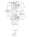
- 3 is a hydraulic circuit diagram including the fluid control device
- FIG. It is a cross-sectional view of a fluid control device of a modification.
- FIG. 11 is a cross-sectional view of another modification of the fluid control device
- 1 is a hydraulic circuit diagram including a conventional fluid control device;
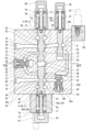
- FIG. 1 to 4 show a fluid control device 1 according to one embodiment
- FIG. 5 shows a hydraulic circuit diagram including the fluid control device 1.
- FIG. This fluid control device 1 is for controlling fluid supplied from a hydraulic pump 10a to a plurality of hydraulic actuators, and is arranged between the hydraulic pump 10a and the plurality of hydraulic actuators in a hydraulic circuit. be done.
- the fluid flowing in the hydraulic circuit is typically oil, but may be a liquid other than oil.
- all the hydraulic actuators are hydraulic actuators 10d that operate bi-directionally by supplying fluid.
- the hydraulic actuators 10d are double-acting cylinders, some or all of the hydraulic actuators 10d may be hydraulic motors.
- the hydraulic actuators may include hydraulic actuators (eg, single-acting cylinders) that are unidirectionally actuated by a supply of fluid.
- the number of hydraulic actuators 10d is five. From the viewpoint of simplification of the drawing, FIG. 5 shows only two hydraulic actuators 10d. However, the number of hydraulic actuators 10d is not limited to this, and can be changed as appropriate.
- the fluid control device 1 includes a plurality of spools 3 for the plurality of hydraulic actuators 10d and a housing 2 that slidably holds these spools 3.
- the fluid control device 1 may include a spool for the hydraulic actuator that operates in one direction by supplying fluid in addition to the spool 3. good.
- the number of spools 3 is the same as the number of hydraulic actuators 10d, but when two hydraulic pumps 10a are used, the fluids discharged from these hydraulic pumps 10a join together to form a hydraulic pressure. Two spools 3 may be used for one hydraulic actuator 10d so as to feed the actuator 10d.
- the spools 3 are parallel to each other and lined up in a specific direction.
- the spools 3 are arranged in a line such that the center lines of all the spools 3 are positioned on the same plane parallel to the specific direction.
- the centerlines of all spools 3 need not lie on the same plane parallel to the specific direction, and the centerlines of some spools 3 may be located away from the plane.
- the spools 3 may be arranged in two rows.
- the housing 2 includes a plurality of spool holes 20 into which spools 3 are respectively inserted. That is, the spool holes 20 are also arranged in the specific direction.
- the housing 2 also includes a pump passage 11 and a tank passage 16 extending in the specific direction. As shown in FIG. 5, the pump passage 11 forms a pump port 1a on the surface of the housing 2, and this pump port 1a is connected to the hydraulic pump 10a by pump piping.
- the tank passage 16 forms a tank port 1b on the surface of the housing 2, which is connected to the tank 10b by a tank pipe.
- the tank passage 16 branches into two branch passages 16a and 16b extending in the specific direction within the housing 2. As shown in FIGS.
- the pump passage 11 passes near the center of the spool 3, and the branch passages 16a and 16b of the tank passage 16 pass near both ends of the spool 3.
- the configurations of the pump passage 11 and the tank passage 16 can be changed as appropriate.
- the housing 2 includes a first supply/discharge passage 14 and a second supply/discharge passage 15 for each of the spools 3 . That is, the number of sets of the first supply/discharge passages 14 and the second supply/discharge passages 15 is the same as the number of spools 3 for the plurality of hydraulic actuators 10d that are bidirectionally operated by the supply of fluid.
- the first supply/discharge passage 14 and the second supply/discharge passage 15 form a pair of supply/discharge ports 1d on the surface of the housing 2, and these supply/discharge ports 1d are connected to the hydraulic actuator 10d by a pair of supply/discharge pipes. be.
- the two spools 3 are the separated spools 3A shown in FIG. 2, and the three spools 3 are the integrated spools 3B shown in FIG.
- the integrated spool 3B and the spaced spool 3A are alternately arranged. That is, the integrated spool 3B is positioned between the separate spools 3A.
- the arrangement of the integrated spool 3B and the spaced spool 3A is not limited to this, and for example, the spaced spool 3A may be adjacent to each other. Also, as long as the spool 3 includes at least one spaced spool 3A, the ratio of the numbers of the integrated spool 3B and the spaced spool 3A can be changed as appropriate. For example, all spools 3 may be separate spools 3A.
- the housing 2 includes a first pilot chamber 7A, a second pilot chamber 7B and a third pilot chamber 7C for each spaced spool 3A and a first pilot chamber 7D and a third pilot chamber 7D for each integral spool 3B. 2 pilot chambers 7E are included.
- the housing 2 includes a rectangular parallelepiped housing main body 2A extending in the specific direction, and a block 2B extending in the specific direction along one side of the housing main body 2A.
- the housing 2 also includes the same number of first covers 2C and second covers 2D as the spaced spool 3A, and the same number of first covers 2E and second covers 2F as the integral spool 3B.
- the configuration of the housing 2 is not limited to this, and can be changed as appropriate.
- a part of the first cover 2C and the first cover 2E may be integrated to form a block extending in the specific direction.
- the housing body 2A has a first side surface 2Aa and a second side surface 2Ab orthogonal to the axial direction of the spool 3, and a third side surface 2Ac and a fourth side surface 2Ad parallel to the specific direction and the axial direction of the spool 3.
- the block 2B is attached to the fourth side surface 2Ad
- the first covers 2C and 2E are attached to the first side surface 2Aa
- the second covers 2D and 2F are attached to the second side surface 2Ab.
- the pump passage 11 described above is formed between the spool hole 20 and the third side surface 2Ac, and the tank passage 16 described above is formed between the spool hole 20 and the fourth side surface 2Ad.
- the pump passage 11 may branch into two branch passages extending in the specific direction within the housing 2 . In this case, one branch path may be positioned between the spool hole 20 and the third side surface 2Ac, and the other branch path may be positioned between the spool hole 20 and the fourth side surface 2Ad.
- first and second supply/discharge passages 14 and 15 for the separate spool 3A and the first and second supply/discharge passages 14 and 15 for the integrated spool 3B are formed in the spool holes 20. and the third side surface 2Ac.
- first supply/discharge passage 14 and the second supply/discharge passage 15 for the integrated spool 3B may be formed between the spool hole 20 and the fourth side surface 2Ad.
- the spool hole 20 into which the separate spool 3A is inserted is the specific spool hole 20A, and the spool hole 20 into which the integrated spool 3B is inserted is the normal spool hole 20B.
- the first cover 2E has a container-like shape, and the first pilot chamber 7D is formed by closing the opening of the first cover 2E with the first side surface 2Aa of the housing body 2A.
- the second cover 2F has a container-like shape, and the second pilot chamber 7E is formed by closing the opening of the second cover 2F with the second side surface 2Ab of the housing body 2A.
- the normal spool hole 20B is a through hole formed in the housing body 2A so as to straddle the first pilot chamber 7D and the second pilot chamber 7E.
- the integrated spool 3B extends across the first supply/discharge passage 14 and the second supply/discharge passage 15, and has an end surface 3a facing the first pilot chamber 7D and an end surface 3b facing the second pilot chamber 7E. .
- the integrated spool 3B has a neutral position in which the first supply/discharge passage 14 and the second supply/discharge passage 15 are blocked from both the pump passage 11 and the tank passage 16, and a state in which the first supply/discharge passage 14 communicates with the pump passage 11.
- a first position (right side position in FIG. 5) where the second supply/discharge passage 15 communicates with the tank passage 16, and a first position where the first supply/discharge passage 14 communicates with the tank passage 16 and the second supply/discharge passage 15 communicates with the pump passage 11. It moves between the communicating second position (the left position in FIG. 5).
- the housing body 2A has a first inflow annular groove 2a, a second inflow annular groove 2b, a first intermediate annular groove 2c, and a second intermediate annular groove which are recessed radially outward from the normal spool hole 20B. 2d, a first outflow annular groove 2e and a second outflow annular groove 2f are formed.
- the first inflow annular groove 2a, the first intermediate annular groove 2c, and the first outflow annular groove 2e are arranged in this order from the center of the normal spool hole 20B toward the first cover 2E. 2b
- the second intermediate annular groove 2d and the second outflow annular groove 2f are arranged in this order from the center of the normal spool hole 20B toward the second cover 2F.
- a bridge passage 19 surrounding the pump passage 11 together with the normal spool hole 20B, and a communication hole 18 communicating the bridge passage 19 and the pump passage 11 are formed in the housing body 2A.
- the communication hole 18 extends from the pump passage 11 in the opposite direction to the normal spool hole 20B and connects to the center of the bridge passage 19. As shown in FIG.
- Both ends of the bridge passage 19 are connected to the first circular inflow groove 2a and the second circular inflow groove 2b. That is, the bridge passage 19 is connected to the normal spool hole 20B via the first annular groove 21 for inflow and the second annular groove 22 for inflow.
- a load check valve 8C that opens and closes the opening of the communication hole 18 with respect to the bridge passage 19 is provided in the housing body 2A.
- the load check valve 8C permits the flow from the pump passage 11 to the bridge passage 19, but prohibits the reverse flow.
- the load check valve 8C includes a body 83 fixed to the housing body 2A, a valve body 81 slidably held by the body 83, and a spring disposed between the body 83 and the valve body 81. 82 included. Since the structure of the load check valve 8C is well known, further detailed description will be omitted.
- the first supply/discharge passage 14 and the second supply/discharge passage 15 for the integrated spool 3B are connected to the first intermediate annular groove 2c and the second intermediate annular groove 2d, respectively, and the branch passages 16a and 16b of the tank passage 16 are respectively connected to the second intermediate annular grooves 2c and 2d. It is connected to the first outflow annular groove 2e and the second outflow annular groove 2f.
- the integrated spool 3B includes a plurality of land portions 31a-31f and a plurality of small diameter portions 32a-32e interposed between the land portions 31a-31f.
- the position where the integrated spool 3B moves from the neutral position toward the first cover 2E is the first position, and the position where it moves from the neutral position toward the second cover 2F is the second position.
- a spring 76 is arranged in the second pilot chamber 7E to apply a biasing force to the integrated spool 3B to maintain the integrated spool 3B in a neutral position.
- a spring 76 urges the integrated spool 3B directly toward the first cover 2E via a spring seat.
- a headed rod 75 is attached to the end face 3b of the integrated spool 3B, and the spring 76 moves the integrated spool 3B through the spring seat and the headed rod 75 toward the second cover 2F. energize.
- a first proportional solenoid valve 64 for the first pilot chamber 7D is attached to the first cover 2E
- a second proportional solenoid valve 65 (see FIG. 1) for the second pilot chamber 7E is attached to the block 2B. It is As shown in FIG. 5, the first proportional electromagnetic valve 64 outputs secondary pressure to the first pilot chamber 7D through the first pilot passage 6d, and the second proportional electromagnetic valve 65 outputs secondary pressure to the second pilot chamber 7D through the second pilot passage 6e. Output the secondary pressure to 7E. From the viewpoint of simplification of the drawing, the illustration of the second pilot passage 6e is omitted in FIG.
- FIG. 1 the structure around the spaced spool 3A and the specific spool hole 20A will be described in detail with reference to FIGS. 2 and 3.
- FIG. 1 the structure around the spaced spool 3A and the specific spool hole 20A will be described in detail with reference to FIGS. 2 and 3.
- FIG. 1 the structure around the spaced spool 3A and the specific spool hole 20A will be described in detail with reference to FIGS. 2 and 3.
- the first cover 2C has a container-like shape, and the first pilot chamber 7A is formed by closing the opening of the first cover 2C with the first side surface 2Aa of the housing body 2A.
- the second cover 2D has a container-like shape, and the second pilot chamber 7B is formed by closing the opening of the second cover 2D with the second side surface 2Ab of the housing body 2A.
- the first cover 2C is divided into a tubular portion and a lid portion, but the configuration of the first cover 2C is not limited to this.
- the specific spool hole 20A is a through hole formed in the housing body 2A so as to straddle the first pilot chamber 7A and the second pilot chamber 7B.
- the spaced spool 3A includes a first spool 4 and a second spool 5 axially spaced from each other within a specific spool bore 20A. A portion between the first spool 4 and the second spool 5 in the specific spool hole 20A constitutes the above-described third pilot chamber 7C.
- the end surface 4a of the first spool 4 on the side opposite to the second spool 5 faces the first pilot chamber 7A
- the end surface 4b on the second spool 5 side faces the third pilot chamber 7C
- the end face 5a of the second spool 5 opposite to the first spool 4 faces the second pilot chamber 7B
- the end face 5b on the first spool 4 side faces the third pilot chamber 7C.
- the first spool 4 has a neutral position in which the first supply/discharge passage 14 is blocked from both the pump passage 11 and the tank passage 16, and a neutral position in which the first supply/discharge passage 14 is disconnected from the tank passage 16 and communicated with the pump passage 11. 5) and a second position (right position in FIG. 5) in which the first supply/discharge passage 14 is blocked from the pump passage 11 and communicated with the tank passage 16. As shown in FIG.
- the second spool 5 has a neutral position in which the second supply/discharge passage 15 is blocked from both the pump passage 11 and the tank passage 16, and a neutral position in which the second supply/discharge passage 15 is disconnected from the pump passage 11 and communicates with the tank passage 16. 5) and a second position (left position in FIG. 5) in which the second supply/discharge passage 15 is blocked from the tank passage 16 and communicated with the pump passage 11. As shown in FIG.
- the first spool 4 communicates the first supply/discharge passage 14 with either the tank passage 16 or the pump passage 11.
- the second spool 5 connects the second supply/discharge passage 15 with the other of the tank passage 16 and the pump passage 11 .
- the housing body 2A has a first inflow annular groove 21, a first intermediate annular groove 23, and a first outflow annular groove 21, which are recessed radially outward from the specific spool hole 20A, in a region overlapping the first spool 4.
- An annular groove 25 is formed.
- the first inflow annular groove 21, the first intermediate annular groove 23, and the first outflow annular groove 25 are arranged in this order from the center of the specific spool hole 20A toward the first cover 2C.
- a second inflow annular groove 22, a second intermediate annular groove 24, and a second outflow annular groove which are recessed radially outward from the specific spool hole 20A, are formed in a region overlapping the second spool 5A. 26 are formed.
- the second inflow annular groove 22, the second intermediate annular groove 24, and the second outflow annular groove 26 are arranged in this order from the center of the specific spool hole 20A toward the second cover 2D.
- the housing body 2A is formed with a bridge passage 13 surrounding the pump passage 11 together with the specific spool hole 20A, and a communication hole 12 that communicates the bridge passage 13 and the pump passage 11 with each other.
- the communication hole 12 extends from the pump passage 11 in the opposite direction to the specific spool hole 20A and connects to the center of the bridge passage 13 .
- Both ends of the bridge passage 13 are connected to the first annular groove 21 for inflow and the second annular groove 22 for inflow. That is, the bridge passage 13 is connected to the specific spool hole 20A via the first annular inflow groove 21 and the second annular inflow groove 22 on both sides of the third pilot chamber 7C.
- a load check valve 8A that opens and closes the opening of the communication hole 12 with respect to the bridge passage 13 is provided in the housing main body 2A.
- the load check valve 8A permits the flow from the pump passage 11 to the bridge passage 13, but prohibits the reverse flow.
- the structure of the load check valve 8A is the same as the structure of the load check valve 8C described above.
- the first supply/discharge passage 14 and the second supply/discharge passage 15 for the spaced spool 3A are connected to the first intermediate annular groove 23 and the second intermediate annular groove 24, respectively, and the branch passages 16a and 16b of the tank passage 16 are respectively connected to the first and second intermediate annular grooves 23 and 24. It is connected to the first outflow annular groove 25 and the second outflow annular groove 26 .
- the first spool 4 includes a first land portion 45 that forms the end surface 4b and opens and closes the first inflow annular groove 21, and a second land portion 45 that is positioned between the first intermediate annular groove 23 and the first outflow annular groove 25. It includes a land portion 43 and a third land portion 41 that constitutes the end surface 4a and is located outside the specific spool hole 20A relative to the first annular groove 25 for outflow. Further, the first spool 4 includes a first small diameter portion 44 connecting the first land portion 45 and the second land portion 43 and a second small diameter portion 42 connecting the second land portion 43 and the third land portion 41. including. As shown in FIG. 2, the state in which the first land portion 45 closes the first annular groove 21 for inflow is the neutral position.
- the first land portion 45 opens the first annular groove 21 for inflow, and the first annular groove 21 for inflow communicates with the first intermediate annular groove 23 . do. This is the first position.
- the first intermediate annular groove 23 communicates with the first outflow annular groove 25 . This is the second position.
- the second spool 5 includes a first land portion 55 forming the end surface 5b positioned closer to the center of the specific spool hole 20A than the second inflow annular groove 22, and a second land opening and closing the second intermediate annular groove 24. and a third land portion 51 that forms the end surface 5a and is positioned outside the specific spool hole 20A relative to the second annular groove 26 for outflow.
- the second spool 5 includes a first small diameter portion 54 connecting the first land portion 55 and the second land portion 53, and a second small diameter portion 52 connecting the second land portion 53 and the third land portion 51. including. As shown in FIG. 2, the state in which the second land portion 53 closes the second intermediate annular groove 24 is the neutral position.
- the second land portion 53 opens the second intermediate annular groove 24 and the second intermediate annular groove 24 communicates with the second outflow annular groove 26 . .
- the second land portion 53 opens the second intermediate annular groove 24, and the second intermediate annular groove 24 opens the second inflow annular groove. 22. This is the second position.
- the shapes of the first spool 4 and the second spool 5 shown in FIG. 1 are merely examples, and the shapes can be changed as appropriate.
- the shape of the first spool 4 and the shape of the second spool 5 may be interchanged.
- a first spring 72 is arranged in the first pilot chamber 7A to apply a biasing force to the first spool 4 to maintain the first spool 4 in a neutral position.
- the first spring 72 urges the first spool 4 directly toward the second spool 5 via the spring seat.
- a headed rod 71 is attached to the end surface 4 a of the first spool 4 , and the first spring 72 connects the first spool 4 with the second spool 5 via the spring seat and the headed rod 71 . Force in the opposite direction.
- a second spring 74 is arranged in the second pilot chamber 7B to apply a biasing force to the second spool 5 to maintain the second spool 5 in the neutral position.
- the second spring 74 urges the second spool 5 directly toward the first spool 4 via the spring seat.
- a headed rod 73 is attached to the end surface 5 a of the second spool 5 , and the second spring 74 connects the second spool 5 with the first spool 4 via the spring seat and the headed rod 73 . Force in the opposite direction.
- the first spring 72 and the second spring 74 have the same configuration. That is, the biasing force applied to the first spool 4 by the first spring 72 and the biasing force applied to the second spool 5 by the second spring 74 are equal.
- the housing 2 has a first pilot passage 6a communicating with the first pilot chamber 7A, a second pilot passage 6b communicating with the second pilot chamber 7B, and a third pilot passage 6b communicating with the third pilot chamber 7C. 3 pilot passages 6c are included. From the viewpoint of simplification of the drawing, illustration of the first pilot passage 6a and the second pilot passage 6b is omitted in FIG.
- a first electromagnetic proportional valve 61 that outputs secondary pressure to the first pilot chamber 7A through the first pilot passage 6a is attached to the first cover 2C.
- the block 2B also includes a second electromagnetic proportional valve 62 (see FIG. 1) that outputs secondary pressure to the second pilot chamber 7B through the second pilot passage 6b, and a third pilot chamber 7C through the third pilot passage 6c.
- a third electromagnetic proportional valve 63 is attached to output the secondary pressure.
- the third electromagnetic proportional valve 63 is attached to the housing 2 at a position opposite to the load check valve 8A with respect to the specific spool hole 20A.
- the housing 2 includes a first proportional solenoid valve 61, a second proportional solenoid valve 62 and a third proportional solenoid valve 63 for the spaced spool 3A, and the above-described first proportional solenoid valve for the integrated spool 3B. It includes a primary pressure passage 60 connected with a proportional valve 64 and a second solenoid proportional valve 65 .
- the primary pressure passage 60 forms a primary pressure port 1c on the surface of the housing 2, and this primary pressure port 1c is connected to the sub-pump 10c by a primary pressure pipe.
- the housing 2 also includes a tank passage 66 that connects the solenoid proportional valves 61-65 with the tank passage 16 described above.
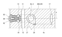
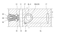
- the third electromagnetic proportional valve 63 is arranged with respect to a plane P perpendicular to the specific direction in which the spools 3 are arranged and passing through the center of the specific spool hole 20A. located away in the direction.
- the third electromagnetic proportional valve 63 may be positioned on the plane P.
- the third pilot passage 6c is located on the side opposite to the load check valve 8A with respect to the pump passage 11 in the specific direction and the direction perpendicular to the axial direction of the spaced spool 3A (that is, the left-right direction in FIG. 2). Located in However, the third pilot passage 6c may be positioned on the same side as the load check valve 8A with respect to the pump passage 11 in the horizontal direction of FIG.
- the housing main body 2A is formed with a central annular groove 27 that is recessed radially outward from the specific spool hole 20A between the first spool 4 and the second spool 5 . Furthermore, as shown in FIG. 3, the housing main body 2A is formed with a recess 28 that is contiguous with the central annular groove 27 and is recessed radially outward from the specific spool hole 20A. The third pilot passage 6c is connected to this recess 28. As shown in FIG. The central annular groove 27 and the recess 28 together with the portion between the first spool 4 and the second spool 5 in the specific spool hole 20A described above constitute the third pilot chamber 7C.
- the depression direction of the depression 28 is the side opposite to the load check valve 8A and oblique to the plane P described above when viewed from the center of the specific spool hole 20A. Therefore, the opening of the third pilot passage 6c to the third pilot chamber 7C is located away from the plane P. However, the opening of the third pilot passage 6c to the third pilot chamber 7C may be positioned on the plane P.
- the third pilot passage 6c extends downward in FIG. 2 from the recess 28, then bends rightward in FIG. 2, and then bends upward in FIG.
- the shape of the third pilot passage 6c can be changed as appropriate.
- the housing body 2A is formed with a regeneration passage 17 for guiding the fluid flowing from the second supply/discharge passage 15 into the specific spool hole 20A to the first supply/discharge passage 14.
- the regeneration passage 17 may be a passage for guiding the fluid flowing from the first supply/discharge passage 14 into the specific spool hole 20A to the second supply/discharge passage 15 .
- the regeneration passage 17 can be omitted. From the viewpoint of simplification of the drawing, FIG. 5 omits the illustration of the regeneration passage 17 and the configuration related thereto.
- the regeneration passage 17 is located on the opposite side of the specific spool hole 20A from the load check valve 8A.
- the regeneration passage 17 extends rightward in FIG. 2 from the second intermediate annular groove 24, bends downward in FIG. 2, and then bends leftward in FIG.
- the third pilot passage 6c partially overlaps the regeneration passage 17 when viewed from the specific direction. Therefore, the regeneration passage 17 and the third pilot passage 6c can be formed on the side opposite to the load check valve 8A with respect to the specific spool hole 20A.
- the housing main body 2A also slidably holds a spool 9 that allows or prohibits the flow of the fluid through the regeneration passage 17, ie, whether or not the fluid is regenerated.
- a cover 2G is attached to the second side surface 2Ab of the housing body 2A, and a pilot chamber 7F for operating the spool 9 is formed by this cover 2G.
- the housing main body 2A is provided with a regeneration valve 8B that permits the fluid to flow through the regeneration passage 17 only when the pressure in the second supply/discharge passage 15 is higher than the pressure in the first supply/discharge passage 14.
- the structure of the regeneration valve 8B is the same as that of the load check valves 8A and 8C.
- two spools are used to connect the first supply/discharge passage 14 and the second supply/discharge passage 15.
- the hydraulic actuator 10d can be operated bi-directionally. Further, since the first spool 4 and the second spool 5 are independent of each other, the first spool 4 can be moved according to the pressure difference between the first pilot chamber 7A and the third pilot chamber 7C. The second spool 5 can be moved according to the pressure difference between the second pilot chamber 7B and the third pilot chamber 7C. This allows independent metering control on either the meter-in side or the meter-out side when the hydraulic actuator 10d operates in either direction. Furthermore, since the number of pilot chambers is three, the number of electromagnetic proportional valves required can be reduced to three. That is, independent metering control is possible using three electromagnetic proportional valves for one hydraulic actuator 10d.
- the secondary pressure of the third electromagnetic proportional valve 63 is set to zero. , that is, a state in which the fluid can be discharged from the third pilot chamber 7C to the tank via the third proportional solenoid valve 63, the secondary pressure of the first proportional solenoid valve 61 and the second proportional solenoid valve 62 is raised from zero. At this time, if the secondary pressure of the first proportional solenoid valve 61 and the secondary pressure of the second proportional solenoid valve 62 are the same, independent metering control is not performed.
- the secondary pressure of the first electromagnetic proportional valve 61 is lower than the secondary pressure of the second electromagnetic proportional valve 62, meter-in control can be performed by the first electromagnetic proportional valve 61, and the second electromagnetic proportional valve 62 is lower than the secondary pressure of the first electromagnetic proportional valve 61, the second electromagnetic proportional valve 62 can perform meter-out control.
- the secondary pressure of the first electromagnetic proportional valve 61 and the first A state in which the secondary pressure of the two electromagnetic proportional valves 62 is zero that is, the fluid can be discharged from the first pilot chamber 7A to the tank via the first electromagnetic proportional valve 61 and the second pilot chamber 7A via the second electromagnetic proportional valve 62 If the secondary pressure of the third electromagnetic proportional valve 63 is increased from zero while the fluid can be discharged from the chamber 7B to the tank, the independent metering control is not performed.
- meter-out control can be performed by the first electromagnetic proportional valve 61, and if the secondary pressure of the second electromagnetic proportional valve 62 is greater than zero.
- meter-in control can be performed by the second electromagnetic proportional valve 62 .
- the opening of the third pilot passage 6c to the third pilot chamber 7C is offset from the center of the specific spool hole 20A in the specific direction in which the spools 3 are arranged.
- the degree of freedom in design is improved.
- the third pilot passage 6c is connected to the recess 28, so the connection position of the third pilot chamber 7C and the third pilot passage 6c can be set at any position.
- the depression 28 allows the opening of the third pilot passage 6c to be largely offset. .
- the third pilot passage 6c is located on the side opposite to the load check valve 8A with respect to the pump passage 11, so complication of passages formed in the housing 2 can be avoided.
- the integral spool 3B is positioned between the spaced spools 3A.
- the spaced-type spools 3A are adjacent to each other, three pilot passages and three electromagnetic proportional valves are required for each spaced-type spool 3A, so the pilot passages and the electromagnetic proportional valves are densely arranged. There is a need to.
- the integrated spool 3B is positioned between the separated spools 3A as in the present embodiment, such dense arrangement of the pilot passages and electromagnetic proportional valves can be alleviated.
- the central annular groove 27 may be omitted and the depression 28 may be directly depressed from the specific spool hole 20A.
- the recess 28 may also be omitted, and the third pilot passage 6c may be directly connected to the specific spool hole 20A.
- the first spool 4 includes a first land portion 48 that forms the end face 4b and opens and closes the first annular groove 21 for inflow, and a first land portion 48 that forms the end face 4a and the first annular groove for outflow. 25 and a small diameter portion 47 connecting the first land portion 48 and the second land portion 46 .
- the spool 9 is used for switching whether or not to regenerate the fluid, but it is also possible to configure so that regeneration is always performed as shown in FIG.
- a regeneration annular groove 29 is formed in the housing body 2A between the second intermediate annular groove 24 and the second outflow annular groove 26.
- the second small diameter portion 52 of the second spool 5 is provided with a land portion 56 located between the regeneration annular groove 29 and the second outflow annular groove 26 .
- the upstream end of the regeneration passage 17 is connected to an annular groove 29 for regeneration.
- the recess direction of the recess 28 may be oblique to the above-described plane P on the side of the load check valve 8A when viewed from the center of the specific spool hole 20A.
- the load check valve 8A may be omitted.
- the third pilot passage 6c is aligned with the center of the specific spool hole 20A in the direction orthogonal to the specific direction and the axial direction of the spaced type spool 3A (that is, the lateral direction in FIG. 2 or FIG. 5). If it is located on the side opposite to the bridge passage 13, it is possible to obtain the effect of avoiding complication of the passage formed in the housing 2 as in the above-described embodiment.
- the present disclosure provides a plurality of spools for a plurality of hydraulic actuators bi-directionally operated by fluid supply, a plurality of spool holes into which the plurality of spools are respectively inserted, pump passages, tank passages, and the plurality of spools.
- a housing including first and second supply and discharge passages for each, wherein at least one of the plurality of spools is a spaced apart type including a first spool and a second spool axially spaced apart from each other.
- the plurality of spool holes includes a specific spool hole into which the spaced-apart spool is inserted; and the first spool blocks the first supply/discharge passage from both the pump passage and the tank passage. Either the pump passage or the tank passage is communicated with the second spool, and the second spool blocks the second supply/discharge passage from both the pump passage and the tank passage.
- the housing includes a first pilot chamber facing the end face of the first spool opposite to the second spool, and a first pilot chamber facing the end face of the second spool opposite to the first spool. including two pilot chambers, a portion between the first spool and the second spool in the specific spool hole constitutes a third pilot chamber, and the housing includes a pilot passage communicating with the third pilot chamber;
- a fluid control device is provided.
- two spools can be used to bi-directionally operate the hydraulic actuator connected to the first supply/discharge passage and the second supply/discharge passage.
- the first spool and the second spool are independent of each other, the first spool can be moved according to the pressure difference between the first pilot chamber and the third pilot chamber, and the second pilot chamber and the second spool can be moved.
- the second spool can be moved according to the pressure difference with the 3 pilot chambers. This allows for independent metering control on either the meter-in or meter-out side when the hydraulic actuator is actuated in either direction.
- the number of pilot chambers is three, the number of electromagnetic proportional valves required can be reduced to three. That is, independent metering control is possible using three electromagnetic proportional valves for one hydraulic actuator.
- the plurality of spools are arranged in a specific direction, and the opening of the pilot passage to the third pilot chamber is separated in the specific direction from a plane perpendicular to the specific direction and passing through the center of the specific spool hole. position. According to this configuration, since the opening of the pilot passage to the third pilot chamber is offset from the center of the specific spool hole in the specific direction, the degree of freedom in designing the periphery of the specific spool hole is improved.
- the housing may include a depression that sharpens radially outward from the specific spool hole, and the pilot passage may be connected to the depression.
- the connection position between the third pilot chamber and the pilot passage can be set at an arbitrary position.
- the recess allows the pilot passage opening to be significantly offset.
- the plurality of spools are arranged in a specific direction, the pump passage extends in the specific direction, and the housing surrounds the pump passage together with the specific spool hole and the specific spool on both sides of the third pilot chamber.
- a bridge passage connected to a hole; and a communication hole communicating between the bridge passage and the pump passage.
- the pilot passage may be located on the side opposite to the load check valve with respect to the pump passage in the specific direction and in a direction perpendicular to the axial direction of the spaced spool. . According to this configuration, since the pilot passage is located on the opposite side of the load check valve with respect to the pump passage, complication of passages formed in the housing can be avoided.
- the housing is a regeneration passage located on the opposite side of the load check valve with respect to the specific spool hole, and flows into the specific spool hole from one of the first supply/discharge passage and the second supply/discharge passage.
- a regeneration passage for guiding fluid to the other of the first supply/discharge passage and the second supply/discharge passage may be included, and the pilot passage may overlap the regeneration passage when viewed from the specific direction. According to this configuration, the regeneration passage and the pilot passage can be formed on the opposite side of the load check valve with respect to the specific spool hole.
- the above fluid control device outputs secondary pressure to the third pilot chamber through the pilot passage, which is attached to the housing at a position opposite to the load check valve with respect to the specific spool hole.
- An electromagnetic proportional valve may be provided.
- the above fluid control device includes an electromagnetic proportional valve that is attached to the housing and outputs secondary pressure to the third pilot chamber through the pilot passage, and the electromagnetic proportional valve is perpendicular to the specific direction. It may be located on a plane passing through the center of the specific spool hole.
- the above fluid control device includes an electromagnetic proportional valve that is attached to the housing and outputs secondary pressure to the third pilot chamber through the pilot passage, and the electromagnetic proportional valve is perpendicular to the specific direction. It may be located away in the specific direction from a plane passing through the center of the specific spool hole.
- the plurality of spools may include a plurality of the spaced spools and an integrated spool located between the spaced spools and spanning the first supply/discharge passage and the second supply/discharge passage.
- each spaced spool requires 3 pilot passages and 3 proportional solenoid valves, so pilot passages and proportional solenoid valves must be densely arranged There is On the other hand, if the integrated spool is positioned between the separated spools, such a dense arrangement of the pilot passages and electromagnetic proportional valves can be alleviated.
- the plurality of spools are arranged in a specific direction, the pump passage extends in the specific direction, and the housing surrounds the pump passage together with the specific spool hole and the specific spool on both sides of the third pilot chamber.
- a bridge passage connected to a hole; and a communication hole communicating between the bridge passage and the pump passage. It may be located on the opposite side of the bridge passage with respect to the center of the particular spool hole.
- the pilot passage is located on the opposite side of the bridge passage with respect to the center of the specific spool hole, so it is possible to avoid complicating the passage formed in the housing.
Abstract
A spaced spool (3A) including a first spool (4) and a second spool (5) axially spaced apart from each other is inserted into a specific spool hole (20A) in a housing (2). The first spool (4) allows a first supply/discharge passage (14) to communicate with either one of a pump passage (11) or a tank passage (16), and the second spool (5) allows a second supply/discharge passage (15) to communicate with the other of the pump passage (11) and the tank passage (16). The housing (2) includes a first pilot chamber (7A) faced by an end surface (4a) of the first spool (4) on the side opposite from the second spool (5), and a second pilot chamber (7B) faced by an end surface (5a) of the second spool (5) on the side opposite from the first spool (4). The portion of the specific spool hole (20A) between the first spool (4) and the second spool (5) constitutes a third pilot chamber (7C), and the housing (2) includes a pilot passage (6c) communicating with the third pilot chamber (7C).
Description
本開示は、液圧ポンプから複数の液圧アクチュエータへ供給される流体を制御するための流体制御装置に関する。
The present disclosure relates to a fluid control device for controlling fluid supplied from a hydraulic pump to a plurality of hydraulic actuators.
従来から、液圧ポンプから複数の液圧アクチュエータへ供給される流体を制御するための流体制御装置が知られている。例えば、流体制御装置は、流体の供給によって双方向に作動する複数の液圧アクチュエータ用の複数のスプールと、前記スプールがそれぞれ挿入された複数のスプール穴を有するハウジングを含む。
Conventionally, a fluid control device for controlling fluid supplied from a hydraulic pump to a plurality of hydraulic actuators has been known. For example, a fluid control device includes a housing having a plurality of spools for a plurality of hydraulic actuators bi-directionally actuated by a supply of fluid and a plurality of spool holes into which the spools are respectively inserted.
ハウジングは、スプール穴に加えて、ポンプ通路およびタンク通路を有するとともに、スプールのそれぞれに対する第1給排通路および第2給排通路を有する。各スプールが中立位置に位置するときは第1給排通路および第2給排通路がポンプ通路およびタンク通路から遮断され、各スプールが中立位置から移動すると、第1給排通路と第2給排通路の一方がポンプ通路と連通し、他方がタンク通路と連通する。
In addition to the spool hole, the housing has a pump passage and a tank passage, and has first and second supply and discharge passages for each of the spools. When each spool is positioned at the neutral position, the first supply/discharge passage and the second supply/discharge passage are blocked from the pump passage and the tank passage. One of the passages communicates with the pump passage and the other communicates with the tank passage.
流体の供給によって双方向に作動する液圧アクチュエータに対しては、どちらの方向に作動するときでも、メータイン側またはメータアウト側で独立メータリング制御を行いたいという要望がある。例えば、特許文献1には、これを実現するための独立メータリング弁が開示されている。
There is a demand for independent metering control on the meter-in side or meter-out side for hydraulic actuators that operate bi-directionally by supplying fluid, regardless of which direction they operate. For example, Patent Literature 1 discloses an independent metering valve for achieving this.
より詳しくは、図8に示すように、特許文献1に開示された独立メータリング弁100は、ポンプポート101と、一対の給排ポート102,103と、タンクポート104を有する。さらに、独立メータリング弁100は、ポンプポート101と給排ポート102の間を開閉する第1スプール130と、給排ポート102とタンクポート104の間を開閉する第2スプール140と、ポンプポート101と給排ポート103の間を開閉する第3スプール150と、給排ポート103とタンクポート104の間を開閉する第4スプール160を含む。
More specifically, as shown in FIG. 8, the independent metering valve 100 disclosed in Patent Document 1 has a pump port 101, a pair of supply/ discharge ports 102 and 103, and a tank port 104. Further, the independent metering valve 100 includes a first spool 130 that opens and closes between the pump port 101 and the supply/discharge port 102, a second spool 140 that opens/closes between the supply/discharge port 102 and the tank port 104, and the pump port 101. and the supply/discharge port 103, and a fourth spool 160 for opening/closing between the supply/discharge port 103 and the tank port 104.
特許文献1には、第1~第4スプール130~160について「電気油圧式変位制御」と記載されている。これは、電気信号がパイロット圧に変換され、そのパイロット圧によってスプールが変位することを意味すると推測される。このような構成では、一般的に電磁比例弁が用いられる。すなわち、独立メータリング弁100には4つの電磁比例弁が必要である。なお、電磁比例弁は独立メータリング弁100に組み込まれてもよいし、独立メータリング弁100と配管により接続されてもよい。
Patent Document 1 describes "electrohydraulic displacement control" for the first to fourth spools 130 to 160. This is presumed to mean that the electrical signal is converted to pilot pressure and the pilot pressure displaces the spool. Electromagnetic proportional valves are generally used in such configurations. That is, the independent metering valve 100 requires four electromagnetic proportional valves. The electromagnetic proportional valve may be incorporated in the independent metering valve 100, or may be connected to the independent metering valve 100 by piping.
特許文献1の独立メータリング弁100では4つのスプールが用いられているので、スプールの数を低減することが望まれる。この点、第1スプール130と第2スプール140とを一体化し、第3スプール150と第4スプール160とを一体化することが考えられる。このような構成でも、独立メータリング制御は可能である。しかし、必要な電磁比例弁の数は4つのままである。
Since four spools are used in the independent metering valve 100 of Patent Document 1, it is desirable to reduce the number of spools. In this respect, it is conceivable to integrate the first spool 130 and the second spool 140 and integrate the third spool 150 and the fourth spool 160 . Even with such a configuration, independent metering control is possible. However, the number of electromagnetic proportional valves required remains four.
そこで、本開示は、少ない電磁比例弁で独立メータリング制御が可能な流体制御装置を提供することを目的とする。
Therefore, an object of the present disclosure is to provide a fluid control device capable of independent metering control with a small number of electromagnetic proportional valves.
本開示は、流体の供給によって双方向に作動する複数の液圧アクチュエータ用の複数のスプールと、前記複数のスプールがそれぞれ挿入された複数のスプール穴、ポンプ通路、タンク通路、前記複数のスプールのそれぞれに対する第1給排通路および第2給排通路を含むハウジングと、を備え、前記複数のスプールのうちの少なくとも1つは、互いに軸方向に離間する第1スプールおよび第2スプールを含む離間型スプールであり、前記複数のスプール穴は、前記離間型スプールが挿入された特定スプール穴を含み、前記第1スプールは、前記第1給排通路を前記ポンプ通路および前記タンク通路の双方から遮断するか前記ポンプ通路と前記タンク通路のどちらか一方と連通させ、前記第2スプールは、前記第2給排通路を前記ポンプ通路および前記タンク通路の双方から遮断するか前記ポンプ通路と前記タンク通路の他方と連通させ、前記ハウジングは、前記第1スプールにおける前記第2スプールと反対側の端面が面する第1パイロット室と、前記第2スプールにおける前記第1スプールと反対側の端面が面する第2パイロット室を含み、前記特定スプール穴における前記第1スプールと前記第2スプールの間の部分が第3パイロット室を構成し、前記ハウジングは、前記第3パイロット室と連通するパイロット通路を含む、流体制御装置を提供する。
The present disclosure provides a plurality of spools for a plurality of hydraulic actuators bi-directionally operated by fluid supply, a plurality of spool holes into which the plurality of spools are respectively inserted, pump passages, tank passages, and the plurality of spools. a housing including first and second supply and discharge passages for each, wherein at least one of the plurality of spools is a spaced apart type including a first spool and a second spool axially spaced apart from each other. a spool, wherein the plurality of spool holes includes a specific spool hole into which the spaced-apart spool is inserted; and the first spool blocks the first supply/discharge passage from both the pump passage and the tank passage. Either the pump passage or the tank passage is communicated with the second spool, and the second spool blocks the second supply/discharge passage from both the pump passage and the tank passage. The housing includes a first pilot chamber facing the end face of the first spool opposite to the second spool, and a first pilot chamber facing the end face of the second spool opposite to the first spool. including two pilot chambers, a portion between the first spool and the second spool in the specific spool hole constitutes a third pilot chamber, and the housing includes a pilot passage communicating with the third pilot chamber; A fluid control device is provided.
本開示によれば、少ない電磁比例弁で独立メータリング制御が可能な流体制御装置が提供される。
According to the present disclosure, a fluid control device capable of independent metering control with a small number of electromagnetic proportional valves is provided.
図1~4に、一実施形態に係る流体制御装置1を示し、図5に流体制御装置1を含む液圧回路図を示す。この流体制御装置1は、液圧ポンプ10aから複数の液圧アクチュエータへ供給される流体を制御するためのものであり、液圧回路において液圧ポンプ10aと複数の液圧アクチュエータとの間に配置される。液圧回路に流れる流体は、典型的には油であるが、油以外の液体であってもよい。
1 to 4 show a fluid control device 1 according to one embodiment, and FIG. 5 shows a hydraulic circuit diagram including the fluid control device 1. FIG. This fluid control device 1 is for controlling fluid supplied from a hydraulic pump 10a to a plurality of hydraulic actuators, and is arranged between the hydraulic pump 10a and the plurality of hydraulic actuators in a hydraulic circuit. be done. The fluid flowing in the hydraulic circuit is typically oil, but may be a liquid other than oil.
本実施形態では、全ての液圧アクチュエータが、流体の供給によって双方向に作動する液圧アクチュエータ10dである。図5では、液圧アクチュエータ10dが複動シリンダであるが、液圧アクチュエータ10dのいくつかまたは全てが液圧モータであってもよい。ただし、液圧アクチュエータは、流体の供給によって一方向に作動する液圧アクチュエータ(例えば、単動シリンダ)を含んでもよい。
In this embodiment, all the hydraulic actuators are hydraulic actuators 10d that operate bi-directionally by supplying fluid. Although in FIG. 5 the hydraulic actuators 10d are double-acting cylinders, some or all of the hydraulic actuators 10d may be hydraulic motors. However, the hydraulic actuators may include hydraulic actuators (eg, single-acting cylinders) that are unidirectionally actuated by a supply of fluid.
本実施形態では、液圧アクチュエータ10dの数が5つである。なお、図面の簡略化の観点から、図5では2つの液圧アクチュエータ10dのみ図示する。ただし、液圧アクチュエータ10dの数はこれに限られるものではなく、適宜変更可能である。
In this embodiment, the number of hydraulic actuators 10d is five. From the viewpoint of simplification of the drawing, FIG. 5 shows only two hydraulic actuators 10d. However, the number of hydraulic actuators 10d is not limited to this, and can be changed as appropriate.
流体制御装置1は、複数の液圧アクチュエータ10d用の複数のスプール3と、これらのスプール3を摺動可能に保持するハウジング2を含む。液圧アクチュエータが流体の供給によって一方向に作動する液圧アクチュエータを含む場合、流体制御装置1は、スプール3に加えて、流体の供給によって一方向に作動する液圧アクチュエータ用のスプールを含んでもよい。本実施形態では、スプール3の数が液圧アクチュエータ10dの数と同じであるが、2つの液圧ポンプ10aが用いられる場合、それらの液圧ポンプ10aから吐出される流体が合流して液圧アクチュエータ10dへ供給されるように、1つの液圧アクチュエータ10dに対して2つのスプール3が用いられてもよい。
The fluid control device 1 includes a plurality of spools 3 for the plurality of hydraulic actuators 10d and a housing 2 that slidably holds these spools 3. When the hydraulic actuator includes a hydraulic actuator that operates in one direction by supplying fluid, the fluid control device 1 may include a spool for the hydraulic actuator that operates in one direction by supplying fluid in addition to the spool 3. good. In this embodiment, the number of spools 3 is the same as the number of hydraulic actuators 10d, but when two hydraulic pumps 10a are used, the fluids discharged from these hydraulic pumps 10a join together to form a hydraulic pressure. Two spools 3 may be used for one hydraulic actuator 10d so as to feed the actuator 10d.
スプール3は、互いに平行であり、特定方向に並んでいる。本実施形態では、全てのスプール3の中心線が前記特定方向と平行な同一平面上に位置するように、スプール3が一列で並んでいる。ただし、全てのスプール3の中心線が前記特定方向と平行な同一平面上に位置する必要はなく、いくつかのスプール3の中心線はその平面から離れた位置に位置してもよい。また、スプール3は二列で並んでもよい。
The spools 3 are parallel to each other and lined up in a specific direction. In this embodiment, the spools 3 are arranged in a line such that the center lines of all the spools 3 are positioned on the same plane parallel to the specific direction. However, the centerlines of all spools 3 need not lie on the same plane parallel to the specific direction, and the centerlines of some spools 3 may be located away from the plane. Alternatively, the spools 3 may be arranged in two rows.
ハウジング2は、スプール3がそれぞれ挿入された複数のスプール穴20を含む。すなわち、スプール穴20も前記特定方向に並んでいる。また、ハウジング2は、前記特定方向に延びるポンプ通路11と、タンク通路16を含む。図5に示すように、ポンプ通路11はハウジング2の表面上でポンプポート1aを形成し、このポンプポート1aがポンプ配管により液圧ポンプ10aと接続される。タンク通路16はハウジング2の表面上でタンクポート1bを形成し、このタンクポートがタンク配管によりタンク10bと接続される。
The housing 2 includes a plurality of spool holes 20 into which spools 3 are respectively inserted. That is, the spool holes 20 are also arranged in the specific direction. The housing 2 also includes a pump passage 11 and a tank passage 16 extending in the specific direction. As shown in FIG. 5, the pump passage 11 forms a pump port 1a on the surface of the housing 2, and this pump port 1a is connected to the hydraulic pump 10a by pump piping. The tank passage 16 forms a tank port 1b on the surface of the housing 2, which is connected to the tank 10b by a tank pipe.
図2,4に示すように、本実施形態では、タンク通路16が、ハウジング2内で前記特定方向に延びる2つの分岐路16a,16bに分岐する。ポンプ通路11はスプール3の中央近くを通過し、タンク通路16の分岐路16a,16bはスプール3の両端近くを通過する。ただし、ポンプ通路11およびタンク通路16の構成は適宜変更可能である。
As shown in FIGS. 2 and 4, in this embodiment, the tank passage 16 branches into two branch passages 16a and 16b extending in the specific direction within the housing 2. As shown in FIGS. The pump passage 11 passes near the center of the spool 3, and the branch passages 16a and 16b of the tank passage 16 pass near both ends of the spool 3. However, the configurations of the pump passage 11 and the tank passage 16 can be changed as appropriate.
さらに、ハウジング2は、スプール3のそれぞれに対して、第1給排通路14および第2給排通路15を含む。つまり、第1給排通路14および第2給排通路15のセットの数は、流体の供給によって双方向に作動する複数の液圧アクチュエータ10d用のスプール3の数と同じである。第1給排通路14および第2給排通路15はハウジング2の表面上で一対の給排ポート1dを形成し、これらの給排ポート1dが一対の給排配管により液圧アクチュエータ10dと接続される。
Furthermore, the housing 2 includes a first supply/discharge passage 14 and a second supply/discharge passage 15 for each of the spools 3 . That is, the number of sets of the first supply/discharge passages 14 and the second supply/discharge passages 15 is the same as the number of spools 3 for the plurality of hydraulic actuators 10d that are bidirectionally operated by the supply of fluid. The first supply/discharge passage 14 and the second supply/discharge passage 15 form a pair of supply/discharge ports 1d on the surface of the housing 2, and these supply/discharge ports 1d are connected to the hydraulic actuator 10d by a pair of supply/discharge pipes. be.
本実施形態では、2つのスプール3が図2に示す離間型スプール3Aであり、3つのスプール3が図4に示す一体型スプール3Bである。一体型スプール3Bと離間型スプール3Aは交互に配置されている。すなわち、離間型スプール3Aの間に一体型スプール3Bが位置する。
In this embodiment, the two spools 3 are the separated spools 3A shown in FIG. 2, and the three spools 3 are the integrated spools 3B shown in FIG. The integrated spool 3B and the spaced spool 3A are alternately arranged. That is, the integrated spool 3B is positioned between the separate spools 3A.
ただし、一体型スプール3Bと離間型スプール3Aの配置はこれに限られるものではなく、例えば離間型スプール3Aが互いに隣り合ってもよい。また、スプール3が少なくとも1つの離間型スプール3Aを含む限り、一体型スプール3Bと離間型スプール3Aの数の比率は適宜変更可能である。例えば、全てのスプール3が離間型スプール3Aであってもよい。
However, the arrangement of the integrated spool 3B and the spaced spool 3A is not limited to this, and for example, the spaced spool 3A may be adjacent to each other. Also, as long as the spool 3 includes at least one spaced spool 3A, the ratio of the numbers of the integrated spool 3B and the spaced spool 3A can be changed as appropriate. For example, all spools 3 may be separate spools 3A.
ハウジング2は、各離間型スプール3Aに対して、第1パイロット室7A、第2パイロット室7Bおよび第3パイロット室7Cを含むとともに、各一体型スプール3Bに対して、第1パイロット室7Dおよび第2パイロット室7Eを含む。
The housing 2 includes a first pilot chamber 7A, a second pilot chamber 7B and a third pilot chamber 7C for each spaced spool 3A and a first pilot chamber 7D and a third pilot chamber 7D for each integral spool 3B. 2 pilot chambers 7E are included.
本実施形態では、ハウジング2が、前記特定方向に延びる直方体状のハウジング本体2Aと、ハウジング本体2Aの一辺に沿って前記特定方向に延びるブロック2Bを含む。また、ハウジング2は、離間型スプール3Aと同数の第1カバー2Cおよび第2カバー2Dと、一体型スプール3Bと同数の第1カバー2Eおよび第2カバー2Fを含む。ただし、ハウジング2の構成はこれに限られるものではなく、適宜変更可能である。例えば、第1カバー2Cの一部と第1カバー2Eが一体となって前記特定方向に延びるブロックを構成してもよい。
In this embodiment, the housing 2 includes a rectangular parallelepiped housing main body 2A extending in the specific direction, and a block 2B extending in the specific direction along one side of the housing main body 2A. The housing 2 also includes the same number of first covers 2C and second covers 2D as the spaced spool 3A, and the same number of first covers 2E and second covers 2F as the integral spool 3B. However, the configuration of the housing 2 is not limited to this, and can be changed as appropriate. For example, a part of the first cover 2C and the first cover 2E may be integrated to form a block extending in the specific direction.
ハウジング本体2Aは、スプール3の軸方向と直交する第1側面2Aaおよび第2側面2Abと、前記特定方向およびスプール3の軸方向と平行な第3側面2Acおよび第4側面2Adを有する。ブロック2Bは第4側面2Adに取り付けられており、第1カバー2C,2Eは第1側面2Aaに取り付けられており、第2カバー2D,2Fは第2側面2Abに取り付けられている。
The housing body 2A has a first side surface 2Aa and a second side surface 2Ab orthogonal to the axial direction of the spool 3, and a third side surface 2Ac and a fourth side surface 2Ad parallel to the specific direction and the axial direction of the spool 3. The block 2B is attached to the fourth side surface 2Ad, the first covers 2C and 2E are attached to the first side surface 2Aa, and the second covers 2D and 2F are attached to the second side surface 2Ab.
本実施形態では、上述したポンプ通路11がスプール穴20と第3側面2Acとの間に形成されており、上述したタンク通路16がスプール穴20と第4側面2Adとの間に形成されている。なお、ポンプ通路11は、ハウジング2内で前記特定方向に延びる2つの分岐路に分岐してもよい。この場合、一方の分岐路がスプール穴20と第3側面2Acとの間に位置し、他方の分岐路がスプール穴20と第4側面2Adとの間に位置してもよい。
In this embodiment, the pump passage 11 described above is formed between the spool hole 20 and the third side surface 2Ac, and the tank passage 16 described above is formed between the spool hole 20 and the fourth side surface 2Ad. . The pump passage 11 may branch into two branch passages extending in the specific direction within the housing 2 . In this case, one branch path may be positioned between the spool hole 20 and the third side surface 2Ac, and the other branch path may be positioned between the spool hole 20 and the fourth side surface 2Ad.
また、本実施形態では、離間型スプール3A用の第1給排通路14および第2給排通路15ならびに一体型スプール3B用の第1給排通路14および第2給排通路15がスプール穴20と第3側面2Acとの間に形成されている。ただし、一体型スプール3B用の第1給排通路14および第2給排通路15はスプール穴20と第4側面2Adとの間に形成されてもよい。
Further, in this embodiment, the first and second supply/ discharge passages 14 and 15 for the separate spool 3A and the first and second supply/ discharge passages 14 and 15 for the integrated spool 3B are formed in the spool holes 20. and the third side surface 2Ac. However, the first supply/discharge passage 14 and the second supply/discharge passage 15 for the integrated spool 3B may be formed between the spool hole 20 and the fourth side surface 2Ad.
スプール穴20のうち離間型スプール3Aが挿入されたスプール穴20は特定スプール穴20Aであり、一体型スプール3Bが挿入されたスプール穴20はノーマルスプール穴20Bである。
Of the spool holes 20, the spool hole 20 into which the separate spool 3A is inserted is the specific spool hole 20A, and the spool hole 20 into which the integrated spool 3B is inserted is the normal spool hole 20B.
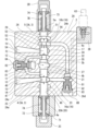
次に、図4を参照して一体型スプール3Bおよびノーマルスプール穴20Bの周囲の構造を詳細に説明する。
Next, the structure around the integrated spool 3B and the normal spool hole 20B will be described in detail with reference to FIG.
第1カバー2Eは容器状の形状を有し、第1カバー2Eの開口がハウジング本体2Aの第1側面2Aaで閉塞されることで第1パイロット室7Dが形成されている。同様に、第2カバー2Fは容器状の形状を有し、第2カバー2Fの開口がハウジング本体2Aの第2側面2Abで閉塞されることで第2パイロット室7Eが形成されている。
The first cover 2E has a container-like shape, and the first pilot chamber 7D is formed by closing the opening of the first cover 2E with the first side surface 2Aa of the housing body 2A. Similarly, the second cover 2F has a container-like shape, and the second pilot chamber 7E is formed by closing the opening of the second cover 2F with the second side surface 2Ab of the housing body 2A.
ノーマルスプール穴20Bは、第1パイロット室7Dと第2パイロット室7Eとに跨るようにハウジング本体2Aに形成された貫通穴である。一体型スプール3Bは、第1給排通路14と第2給排通路15とに跨って延びており、第1パイロット室7Dに面する端面3aと第2パイロット室7Eに面する端面3bを有する。
The normal spool hole 20B is a through hole formed in the housing body 2A so as to straddle the first pilot chamber 7D and the second pilot chamber 7E. The integrated spool 3B extends across the first supply/discharge passage 14 and the second supply/discharge passage 15, and has an end surface 3a facing the first pilot chamber 7D and an end surface 3b facing the second pilot chamber 7E. .
一体型スプール3Bは、第1給排通路14および第2給排通路15をポンプ通路11およびタンク通路16の双方から遮断する中立位置と、第1給排通路14をポンプ通路11と連通させるとともに第2給排通路15をタンク通路16と連通させる第1位置(図5の右側位置)と、第1給排通路14をタンク通路16と連通させるとともに第2給排通路15をポンプ通路11と連通させる第2位置(図5の左側位置)との間で移動する。
The integrated spool 3B has a neutral position in which the first supply/discharge passage 14 and the second supply/discharge passage 15 are blocked from both the pump passage 11 and the tank passage 16, and a state in which the first supply/discharge passage 14 communicates with the pump passage 11. A first position (right side position in FIG. 5) where the second supply/discharge passage 15 communicates with the tank passage 16, and a first position where the first supply/discharge passage 14 communicates with the tank passage 16 and the second supply/discharge passage 15 communicates with the pump passage 11. It moves between the communicating second position (the left position in FIG. 5).
より詳しくは、ハウジング本体2Aには、ノーマルスプール穴20Bから径方向外向きに窪む第1流入用環状溝2a、第2流入用環状溝2b、第1中間環状溝2c、第2中間環状溝2d、第1流出用環状溝2eおよび第2流出用環状溝2fが形成されている。第1流入用環状溝2a、第1中間環状溝2cおよび第1流出用環状溝2eは、ノーマルスプール穴20Bの中央から第1カバー2Eに向かってこの順に並んでおり、第2流入用環状溝2b、第2中間環状溝2dおよび第2流出用環状溝2fは、ノーマルスプール穴20Bの中央から第2カバー2Fに向かってこの順に並んでいる。
More specifically, the housing body 2A has a first inflow annular groove 2a, a second inflow annular groove 2b, a first intermediate annular groove 2c, and a second intermediate annular groove which are recessed radially outward from the normal spool hole 20B. 2d, a first outflow annular groove 2e and a second outflow annular groove 2f are formed. The first inflow annular groove 2a, the first intermediate annular groove 2c, and the first outflow annular groove 2e are arranged in this order from the center of the normal spool hole 20B toward the first cover 2E. 2b, the second intermediate annular groove 2d and the second outflow annular groove 2f are arranged in this order from the center of the normal spool hole 20B toward the second cover 2F.
また、ハウジング本体2Aには、ノーマルスプール穴20Bと共にポンプ通路11を取り囲むブリッジ通路19と、ブリッジ通路19とポンプ通路11とを連通する連通穴18が形成されている。連通穴18は、ポンプ通路11からノーマルスプール穴20Bと反対向きに延びていてブリッジ通路19の中央につながっている。
In addition, a bridge passage 19 surrounding the pump passage 11 together with the normal spool hole 20B, and a communication hole 18 communicating the bridge passage 19 and the pump passage 11 are formed in the housing body 2A. The communication hole 18 extends from the pump passage 11 in the opposite direction to the normal spool hole 20B and connects to the center of the bridge passage 19. As shown in FIG.
ブリッジ通路19の両端は、第1流入用環状溝2aおよび第2流入用環状溝2bにつながっている。つまり、ブリッジ通路19は、第1流入用環状溝21および第2流入用環状溝22を介してノーマルスプール穴20Bと接続されている。
Both ends of the bridge passage 19 are connected to the first circular inflow groove 2a and the second circular inflow groove 2b. That is, the bridge passage 19 is connected to the normal spool hole 20B via the first annular groove 21 for inflow and the second annular groove 22 for inflow.
ハウジング本体2Aには、ブリッジ通路19に対する連通穴18の開口を開閉するロードチェック弁8Cが設けられている。ロードチェック弁8Cは、ポンプ通路11からブリッジ通路19へ向かう流れは許容するがその逆の流れは禁止する。
A load check valve 8C that opens and closes the opening of the communication hole 18 with respect to the bridge passage 19 is provided in the housing body 2A. The load check valve 8C permits the flow from the pump passage 11 to the bridge passage 19, but prohibits the reverse flow.
具体的に、ロードチェック弁8Cは、ハウジング本体2Aに固定された本体83と、本体83に摺動可能に保持された弁体81と、本体83と弁体81との間に配置されたスプリング82を含む。なお、ロードチェック弁8Cの構造は公知であるため、それ以上の詳細な説明は省略する。
Specifically, the load check valve 8C includes a body 83 fixed to the housing body 2A, a valve body 81 slidably held by the body 83, and a spring disposed between the body 83 and the valve body 81. 82 included. Since the structure of the load check valve 8C is well known, further detailed description will be omitted.
一体型スプール3B用の第1給排通路14および第2給排通路15はそれぞれ第1中間環状溝2cおよび第2中間環状溝2dに接続され、タンク通路16の分岐路16a,16bはそれぞれ第1流出用環状溝2eおよび第2流出用環状溝2fに接続されている。
The first supply/discharge passage 14 and the second supply/discharge passage 15 for the integrated spool 3B are connected to the first intermediate annular groove 2c and the second intermediate annular groove 2d, respectively, and the branch passages 16a and 16b of the tank passage 16 are respectively connected to the second intermediate annular grooves 2c and 2d. It is connected to the first outflow annular groove 2e and the second outflow annular groove 2f.
一体型スプール3Bは、複数のランド部31a~31fと、これらのランド部31a~31fの間に介在する複数の小径部32a~32eを含む。一体型スプール3Bが中立位置から第1カバー2Eに向かって移動した位置が第1位置であり、中立位置から第2カバー2Fに向かって移動した位置が第2位置である。
The integrated spool 3B includes a plurality of land portions 31a-31f and a plurality of small diameter portions 32a-32e interposed between the land portions 31a-31f. The position where the integrated spool 3B moves from the neutral position toward the first cover 2E is the first position, and the position where it moves from the neutral position toward the second cover 2F is the second position.
第2パイロット室7E内には、一体型スプール3Bに当該一体型スプール3Bを中立位置に維持するための付勢力を与えるスプリング76が配置されている。スプリング76は、一体型スプール3Bを、スプリング座を介して第1カバー2Eに向かって直接的に付勢する。一方、一体型スプール3Bの端面3bには頭部付ロッド75が取り付けられており、スプリング76は、一体型スプール3Bを、スプリング座および頭部付ロッド75を介して第2カバー2Fに向かって付勢する。
A spring 76 is arranged in the second pilot chamber 7E to apply a biasing force to the integrated spool 3B to maintain the integrated spool 3B in a neutral position. A spring 76 urges the integrated spool 3B directly toward the first cover 2E via a spring seat. On the other hand, a headed rod 75 is attached to the end face 3b of the integrated spool 3B, and the spring 76 moves the integrated spool 3B through the spring seat and the headed rod 75 toward the second cover 2F. energize.
本実施形態では、第1カバー2Eに第1パイロット室7D用の第1電磁比例弁64が取り付けられ、ブロック2Bに第2パイロット室7E用の第2電磁比例弁65(図1参照)が取り付けられている。図5に示すように、第1電磁比例弁64は第1パイロット通路6dを通じて第1パイロット室7Dへ二次圧を出力し、第2電磁比例弁65は第2パイロット通路6eを通じて第2パイロット室7Eへ二次圧を出力する。なお、図面の簡略化の観点から、図4では第2パイロット通路6eの図示は省略する。
In this embodiment, a first proportional solenoid valve 64 for the first pilot chamber 7D is attached to the first cover 2E, and a second proportional solenoid valve 65 (see FIG. 1) for the second pilot chamber 7E is attached to the block 2B. It is As shown in FIG. 5, the first proportional electromagnetic valve 64 outputs secondary pressure to the first pilot chamber 7D through the first pilot passage 6d, and the second proportional electromagnetic valve 65 outputs secondary pressure to the second pilot chamber 7D through the second pilot passage 6e. Output the secondary pressure to 7E. From the viewpoint of simplification of the drawing, the illustration of the second pilot passage 6e is omitted in FIG.
次に、図2および図3を参照して離間型スプール3Aおよび特定スプール穴20Aの周囲の構造を詳細に説明する。
Next, the structure around the spaced spool 3A and the specific spool hole 20A will be described in detail with reference to FIGS. 2 and 3. FIG.
第1カバー2Cは容器状の形状を有し、第1カバー2Cの開口がハウジング本体2Aの第1側面2Aaで閉塞されることで第1パイロット室7Aが形成されている。同様に、第2カバー2Dは容器状の形状を有し、第2カバー2Dの開口がハウジング本体2Aの第2側面2Abで閉塞されることで第2パイロット室7Bが形成されている。本実施形態では、第1カバー2Cが筒状部と蓋部とに分割されているが、第1カバー2Cの構成はこれに限られるものではない。
The first cover 2C has a container-like shape, and the first pilot chamber 7A is formed by closing the opening of the first cover 2C with the first side surface 2Aa of the housing body 2A. Similarly, the second cover 2D has a container-like shape, and the second pilot chamber 7B is formed by closing the opening of the second cover 2D with the second side surface 2Ab of the housing body 2A. In this embodiment, the first cover 2C is divided into a tubular portion and a lid portion, but the configuration of the first cover 2C is not limited to this.
特定スプール穴20Aは、第1パイロット室7Aと第2パイロット室7Bとに跨るようにハウジング本体2Aに形成された貫通穴である。離間型スプール3Aは、特定スプール穴20A内で互いに軸方向に離間する第1スプール4および第2スプール5を含む。特定スプール穴20Aにおける第1スプール4と第2スプール5の間の部分が上述した第3パイロット室7Cを構成する。
The specific spool hole 20A is a through hole formed in the housing body 2A so as to straddle the first pilot chamber 7A and the second pilot chamber 7B. The spaced spool 3A includes a first spool 4 and a second spool 5 axially spaced from each other within a specific spool bore 20A. A portion between the first spool 4 and the second spool 5 in the specific spool hole 20A constitutes the above-described third pilot chamber 7C.
つまり、第1スプール4における第2スプール5と反対側の端面4aが第1パイロット室7Aに面し、第2スプール5側の端面4bが第3パイロット室7Cに面する。同様に、第2スプール5における第1スプール4と反対側の端面5aが第2パイロット室7Bに面し、第1スプール4側の端面5bが第3パイロット室7Cに面する。
That is, the end surface 4a of the first spool 4 on the side opposite to the second spool 5 faces the first pilot chamber 7A, and the end surface 4b on the second spool 5 side faces the third pilot chamber 7C. Similarly, the end face 5a of the second spool 5 opposite to the first spool 4 faces the second pilot chamber 7B, and the end face 5b on the first spool 4 side faces the third pilot chamber 7C.
第1スプール4は、第1給排通路14をポンプ通路11およびタンク通路16の双方から遮断する中立位置と、第1給排通路14をタンク通路16から遮断しつつポンプ通路11と連通させる第1位置(図5の左側位置)と、第1給排通路14をポンプ通路11から遮断しつつタンク通路16と連通させる第2位置(図5の右側位置)との間で移動する。
The first spool 4 has a neutral position in which the first supply/discharge passage 14 is blocked from both the pump passage 11 and the tank passage 16, and a neutral position in which the first supply/discharge passage 14 is disconnected from the tank passage 16 and communicated with the pump passage 11. 5) and a second position (right position in FIG. 5) in which the first supply/discharge passage 14 is blocked from the pump passage 11 and communicated with the tank passage 16. As shown in FIG.
第2スプール5は、第2給排通路15をポンプ通路11およびタンク通路16の双方から遮断する中立位置と、第2給排通路15をポンプ通路11から遮断しつつタンク通路16と連通させる第1位置(図5の右側位置)と、第2給排通路15をタンク通路16から遮断しつつポンプ通路11と連通させる第2位置(図5の左側位置)との間で移動する。
The second spool 5 has a neutral position in which the second supply/discharge passage 15 is blocked from both the pump passage 11 and the tank passage 16, and a neutral position in which the second supply/discharge passage 15 is disconnected from the pump passage 11 and communicates with the tank passage 16. 5) and a second position (left position in FIG. 5) in which the second supply/discharge passage 15 is blocked from the tank passage 16 and communicated with the pump passage 11. As shown in FIG.
すなわち、第1スプール4および第2スプール5が共に第1位置または第2位置に位置するとき、第1スプール4が第1給排通路14をタンク通路16とポンプ通路11のどちらか一方と連通させ、第2スプール5が第2給排通路15をタンク通路16とポンプ通路11の他方と連通させる。
That is, when both the first spool 4 and the second spool 5 are positioned at the first position or the second position, the first spool 4 communicates the first supply/discharge passage 14 with either the tank passage 16 or the pump passage 11. The second spool 5 connects the second supply/discharge passage 15 with the other of the tank passage 16 and the pump passage 11 .
より詳しくは、ハウジング本体2Aには、第1スプール4と重なり合う領域に、特定スプール穴20Aから径方向外向きに窪む第1流入用環状溝21、第1中間環状溝23および第1流出用環状溝25が形成されている。第1流入用環状溝21、第1中間環状溝23および第1流出用環状溝25は、特定スプール穴20Aの中央から第1カバー2Cに向かってこの順に並んでいる。
More specifically, the housing body 2A has a first inflow annular groove 21, a first intermediate annular groove 23, and a first outflow annular groove 21, which are recessed radially outward from the specific spool hole 20A, in a region overlapping the first spool 4. An annular groove 25 is formed. The first inflow annular groove 21, the first intermediate annular groove 23, and the first outflow annular groove 25 are arranged in this order from the center of the specific spool hole 20A toward the first cover 2C.
また、ハウジング本体2Aには、第2スプール5と重なり合う領域に、特定スプール穴20Aから径方向外向きに窪む第2流入用環状溝22、第2中間環状溝24および第2流出用環状溝26が形成されている。第2流入用環状溝22、第2中間環状溝24および第2流出用環状溝26は、特定スプール穴20Aの中央から第2カバー2Dに向かってこの順に並んでいる。
In the housing body 2A, a second inflow annular groove 22, a second intermediate annular groove 24, and a second outflow annular groove, which are recessed radially outward from the specific spool hole 20A, are formed in a region overlapping the second spool 5A. 26 are formed. The second inflow annular groove 22, the second intermediate annular groove 24, and the second outflow annular groove 26 are arranged in this order from the center of the specific spool hole 20A toward the second cover 2D.
さらに、ハウジング本体2Aには、特定スプール穴20Aと共にポンプ通路11を取り囲むブリッジ通路13と、ブリッジ通路13とポンプ通路11とを連通する連通穴12が形成されている。連通穴12は、ポンプ通路11から特定スプール穴20Aと反対向きに延びていてブリッジ通路13の中央につながっている。
Further, the housing body 2A is formed with a bridge passage 13 surrounding the pump passage 11 together with the specific spool hole 20A, and a communication hole 12 that communicates the bridge passage 13 and the pump passage 11 with each other. The communication hole 12 extends from the pump passage 11 in the opposite direction to the specific spool hole 20A and connects to the center of the bridge passage 13 .
ブリッジ通路13の両端は、第1流入用環状溝21および第2流入用環状溝22につながっている。つまり、ブリッジ通路13は、第3パイロット室7Cの両側で第1流入用環状溝21および第2流入用環状溝22を介して特定スプール穴20Aと接続されている。
Both ends of the bridge passage 13 are connected to the first annular groove 21 for inflow and the second annular groove 22 for inflow. That is, the bridge passage 13 is connected to the specific spool hole 20A via the first annular inflow groove 21 and the second annular inflow groove 22 on both sides of the third pilot chamber 7C.
ハウジング本体2Aには、ブリッジ通路13に対する連通穴12の開口を開閉するロードチェック弁8Aが設けられている。ロードチェック弁8Aは、ポンプ通路11からブリッジ通路13へ向かう流れは許容するがその逆の流れは禁止する。なお、ロードチェック弁8Aの構造は上述したロードチェック弁8Cの構造と同じである。
A load check valve 8A that opens and closes the opening of the communication hole 12 with respect to the bridge passage 13 is provided in the housing main body 2A. The load check valve 8A permits the flow from the pump passage 11 to the bridge passage 13, but prohibits the reverse flow. The structure of the load check valve 8A is the same as the structure of the load check valve 8C described above.
離間型スプール3A用の第1給排通路14および第2給排通路15はそれぞれ第1中間環状溝23および第2中間環状溝24に接続され、タンク通路16の分岐路16a,16bはそれぞれ第1流出用環状溝25および第2流出用環状溝26に接続されている。
The first supply/discharge passage 14 and the second supply/discharge passage 15 for the spaced spool 3A are connected to the first intermediate annular groove 23 and the second intermediate annular groove 24, respectively, and the branch passages 16a and 16b of the tank passage 16 are respectively connected to the first and second intermediate annular grooves 23 and 24. It is connected to the first outflow annular groove 25 and the second outflow annular groove 26 .
第1スプール4は、端面4bを構成するとともに第1流入用環状溝21を開閉する第1ランド部45と、第1中間環状溝23と第1流出用環状溝25の間に位置する第2ランド部43と、第1流出用環状溝25よりも特定スプール穴20Aの外側に位置する、端面4aを構成する第3ランド部41を含む。さらに、第1スプール4は、第1ランド部45と第2ランド部43とを連結する第1小径部44と、第2ランド部43と第3ランド部41とを連結する第2小径部42を含む。図2に示すように、第1ランド部45が第1流入用環状溝21を閉じる状態が中立位置である。
The first spool 4 includes a first land portion 45 that forms the end surface 4b and opens and closes the first inflow annular groove 21, and a second land portion 45 that is positioned between the first intermediate annular groove 23 and the first outflow annular groove 25. It includes a land portion 43 and a third land portion 41 that constitutes the end surface 4a and is located outside the specific spool hole 20A relative to the first annular groove 25 for outflow. Further, the first spool 4 includes a first small diameter portion 44 connecting the first land portion 45 and the second land portion 43 and a second small diameter portion 42 connecting the second land portion 43 and the third land portion 41. including. As shown in FIG. 2, the state in which the first land portion 45 closes the first annular groove 21 for inflow is the neutral position.
第1スプール4が中立位置から第2スプール5に向かって移動すると、第1ランド部45が第1流入用環状溝21を開き、第1流入用環状溝21が第1中間環状溝23と連通する。これが第1位置である。逆に、第1スプール4が中立位置から第2スプール5と反対向きに移動すると、第1中間環状溝23が第1流出用環状溝25と連通する。これが第2位置である。
When the first spool 4 moves from the neutral position toward the second spool 5 , the first land portion 45 opens the first annular groove 21 for inflow, and the first annular groove 21 for inflow communicates with the first intermediate annular groove 23 . do. This is the first position. Conversely, when the first spool 4 moves in the direction opposite to the second spool 5 from the neutral position, the first intermediate annular groove 23 communicates with the first outflow annular groove 25 . This is the second position.
第2スプール5は、第2流入用環状溝22よりも特定スプール穴20Aの中央側に位置する、端面5bを構成する第1ランド部55と、第2中間環状溝24を開閉する第2ランド部53と、第2流出用環状溝26よりも特定スプール穴20Aの外側に位置する、端面5aを構成する第3ランド部51を含む。さらに、第2スプール5は、第1ランド部55と第2ランド部53とを連結する第1小径部54と、第2ランド部53と第3ランド部51とを連結する第2小径部52を含む。図2に示すように、第2ランド部53が第2中間環状溝24を閉じる状態が中立位置である。
The second spool 5 includes a first land portion 55 forming the end surface 5b positioned closer to the center of the specific spool hole 20A than the second inflow annular groove 22, and a second land opening and closing the second intermediate annular groove 24. and a third land portion 51 that forms the end surface 5a and is positioned outside the specific spool hole 20A relative to the second annular groove 26 for outflow. Further, the second spool 5 includes a first small diameter portion 54 connecting the first land portion 55 and the second land portion 53, and a second small diameter portion 52 connecting the second land portion 53 and the third land portion 51. including. As shown in FIG. 2, the state in which the second land portion 53 closes the second intermediate annular groove 24 is the neutral position.
第2スプール5が中立位置から第1スプール4に向かって移動すると、第2ランド部53が第2中間環状溝24を開き、第2中間環状溝24が第2流出用環状溝26と連通する。これが第1位置である。逆に、第2スプール5が中立位置から第1スプール4と反対向きに移動すると、第2ランド部53が第2中間環状溝24を開き、第2中間環状溝24が第2流入用環状溝22と連通する。これが第2位置である。
When the second spool 5 moves from the neutral position toward the first spool 4 , the second land portion 53 opens the second intermediate annular groove 24 and the second intermediate annular groove 24 communicates with the second outflow annular groove 26 . . This is the first position. Conversely, when the second spool 5 moves from the neutral position in the opposite direction to the first spool 4, the second land portion 53 opens the second intermediate annular groove 24, and the second intermediate annular groove 24 opens the second inflow annular groove. 22. This is the second position.
なお、図1に示す第1スプール4および第2スプール5の形状は単なる一例であり、それらの形状は適宜変更可能である。例えば、第1スプール4の形状と第2スプール5の形状が入れ替わってもよい。
The shapes of the first spool 4 and the second spool 5 shown in FIG. 1 are merely examples, and the shapes can be changed as appropriate. For example, the shape of the first spool 4 and the shape of the second spool 5 may be interchanged.
第1パイロット室7A内には、第1スプール4に当該第1スプール4を中立位置に維持するための付勢力を与える第1スプリング72が配置されている。第1スプリング72は、第1スプール4を、スプリング座を介して第2スプール5に向かって直接的に付勢する。一方、第1スプール4の端面4aには頭部付ロッド71が取り付けられており、第1スプリング72は、第1スプール4を、スプリング座および頭部付ロッド71を介して第2スプール5と反対向きに付勢する。
A first spring 72 is arranged in the first pilot chamber 7A to apply a biasing force to the first spool 4 to maintain the first spool 4 in a neutral position. The first spring 72 urges the first spool 4 directly toward the second spool 5 via the spring seat. On the other hand, a headed rod 71 is attached to the end surface 4 a of the first spool 4 , and the first spring 72 connects the first spool 4 with the second spool 5 via the spring seat and the headed rod 71 . Force in the opposite direction.
同様に、第2パイロット室7B内には、第2スプール5に当該第2スプール5を中立位置に維持するための付勢力を与える第2スプリング74が配置されている。第2スプリング74は、第2スプール5を、スプリング座を介して第1スプール4に向かって直接的に付勢する。一方、第2スプール5の端面5aには頭部付ロッド73が取り付けられており、第2スプリング74は、第2スプール5を、スプリング座および頭部付ロッド73を介して第1スプール4と反対向きに付勢する。
Similarly, a second spring 74 is arranged in the second pilot chamber 7B to apply a biasing force to the second spool 5 to maintain the second spool 5 in the neutral position. The second spring 74 urges the second spool 5 directly toward the first spool 4 via the spring seat. On the other hand, a headed rod 73 is attached to the end surface 5 a of the second spool 5 , and the second spring 74 connects the second spool 5 with the first spool 4 via the spring seat and the headed rod 73 . Force in the opposite direction.
第1スプリング72と第2スプリング74は互いに同じ構成を有する。すなわち、第1スプリング72が第1スプール4に与える付勢力と、第2スプリング74が第2スプール5に与える付勢力は等しい。
The first spring 72 and the second spring 74 have the same configuration. That is, the biasing force applied to the first spool 4 by the first spring 72 and the biasing force applied to the second spool 5 by the second spring 74 are equal.
ハウジング2は、図5に示すように、第1パイロット室7Aと連通する第1パイロット通路6aと、第2パイロット室7Bと連通する第2パイロット通路6bと、第3パイロット室7Cと連通する第3パイロット通路6cを含む。なお、図面の簡略化の観点から、図2では第1パイロット通路6aおよび第2パイロット通路6bの図示は省略する。
As shown in FIG. 5, the housing 2 has a first pilot passage 6a communicating with the first pilot chamber 7A, a second pilot passage 6b communicating with the second pilot chamber 7B, and a third pilot passage 6b communicating with the third pilot chamber 7C. 3 pilot passages 6c are included. From the viewpoint of simplification of the drawing, illustration of the first pilot passage 6a and the second pilot passage 6b is omitted in FIG.
本実施形態では、第1カバー2Cに、第1パイロット通路6aを通じて第1パイロット室7Aへ二次圧を出力する第1電磁比例弁61が取り付けられている。また、ブロック2Bには、第2パイロット通路6bを通じて第2パイロット室7Bへ二次圧を出力する第2電磁比例弁62(図1参照)と、第3パイロット通路6cを通じて第3パイロット室7Cへ二次圧を出力する第3電磁比例弁63が取り付けられている。換言すれば、第3電磁比例弁63は、特定スプール穴20Aに対してロードチェック弁8Aとは反対側の位置でハウジング2に取り付けられている。
In this embodiment, a first electromagnetic proportional valve 61 that outputs secondary pressure to the first pilot chamber 7A through the first pilot passage 6a is attached to the first cover 2C. The block 2B also includes a second electromagnetic proportional valve 62 (see FIG. 1) that outputs secondary pressure to the second pilot chamber 7B through the second pilot passage 6b, and a third pilot chamber 7C through the third pilot passage 6c. A third electromagnetic proportional valve 63 is attached to output the secondary pressure. In other words, the third electromagnetic proportional valve 63 is attached to the housing 2 at a position opposite to the load check valve 8A with respect to the specific spool hole 20A.
図5に示すように、ハウジング2は、離間型スプール3A用の第1電磁比例弁61、第2電磁比例弁62および第3電磁比例弁63、ならびに上述した一体型スプール3B用の第1電磁比例弁64および第2電磁比例弁65と接続された一次圧通路60を含む。一次圧通路60はハウジング2の表面上で一次圧ポート1cを形成し、この一次圧ポート1cが一次圧配管により副ポンプ10cと接続される。また、ハウジング2は、電磁比例弁61~65を上述したタンク通路16と接続するタンク通路66を含む。
As shown in FIG. 5, the housing 2 includes a first proportional solenoid valve 61, a second proportional solenoid valve 62 and a third proportional solenoid valve 63 for the spaced spool 3A, and the above-described first proportional solenoid valve for the integrated spool 3B. It includes a primary pressure passage 60 connected with a proportional valve 64 and a second solenoid proportional valve 65 . The primary pressure passage 60 forms a primary pressure port 1c on the surface of the housing 2, and this primary pressure port 1c is connected to the sub-pump 10c by a primary pressure pipe. The housing 2 also includes a tank passage 66 that connects the solenoid proportional valves 61-65 with the tank passage 16 described above.
本実施形態では、図1に示すように、第3電磁比例弁63が、スプール3が並ぶ前記特定方向と直交する面Pであって特定スプール穴20Aの中心を通る面Pに対して前記特定方向に離れた位置にある。ただし、第3電磁比例弁63は面P上に位置してもよい。
In the present embodiment, as shown in FIG. 1, the third electromagnetic proportional valve 63 is arranged with respect to a plane P perpendicular to the specific direction in which the spools 3 are arranged and passing through the center of the specific spool hole 20A. located away in the direction. However, the third electromagnetic proportional valve 63 may be positioned on the plane P.
本実施形態では、前記特定方向および離間型スプール3Aの軸方向と直交する方向(すなわち、図2の左右方向)において、第3パイロット通路6cがポンプ通路11に対してロードチェック弁8Aと反対側に位置する。ただし、図2の左右方向において、第3パイロット通路6cがポンプ通路11に対してロードチェック弁8Aと同じ側に位置してもよい。
In this embodiment, the third pilot passage 6c is located on the side opposite to the load check valve 8A with respect to the pump passage 11 in the specific direction and the direction perpendicular to the axial direction of the spaced spool 3A (that is, the left-right direction in FIG. 2). Located in However, the third pilot passage 6c may be positioned on the same side as the load check valve 8A with respect to the pump passage 11 in the horizontal direction of FIG.
より詳しくは、ハウジング本体2Aには、第1スプール4と第2スプール5との間で特定スプール穴20Aから径方向外向きに窪む中央環状溝27が形成されている。さらに、ハウジング本体2Aには、図3に示すように、中央環状溝27と連続する、特定スプール穴20Aから径方向外向きに尖るように窪む窪み28が形成されている。第3パイロット通路6cは、この窪み28に接続されている。中央環状溝27および窪み28は、上述した特定スプール穴20Aにおける第1スプール4と第2スプール5の間の部分と共に第3パイロット室7Cを構成する。
More specifically, the housing main body 2A is formed with a central annular groove 27 that is recessed radially outward from the specific spool hole 20A between the first spool 4 and the second spool 5 . Furthermore, as shown in FIG. 3, the housing main body 2A is formed with a recess 28 that is contiguous with the central annular groove 27 and is recessed radially outward from the specific spool hole 20A. The third pilot passage 6c is connected to this recess 28. As shown in FIG. The central annular groove 27 and the recess 28 together with the portion between the first spool 4 and the second spool 5 in the specific spool hole 20A described above constitute the third pilot chamber 7C.
本実施形態では、窪み28の窪み方向が、特定スプール穴20Aの中心から見て、ロードチェック弁8Aと反対側であって上述した面Pに対して斜めの方向である。このため、第3パイロット室7Cに対する第3パイロット通路6cの開口は面Pから離れた位置にある。ただし、第3パイロット室7Cに対する第3パイロット通路6cの開口は面P上に位置してもよい。
In this embodiment, the depression direction of the depression 28 is the side opposite to the load check valve 8A and oblique to the plane P described above when viewed from the center of the specific spool hole 20A. Therefore, the opening of the third pilot passage 6c to the third pilot chamber 7C is located away from the plane P. However, the opening of the third pilot passage 6c to the third pilot chamber 7C may be positioned on the plane P.
本実施形態では、第3パイロット通路6cが、窪み28から図2において下向きに延びた後に、図2において右向きに折れ曲がり、さらにその後に図2において上向きに折れ曲がっている。ただし、第3パイロット通路6cの形状は適宜変更可能である。
In this embodiment, the third pilot passage 6c extends downward in FIG. 2 from the recess 28, then bends rightward in FIG. 2, and then bends upward in FIG. However, the shape of the third pilot passage 6c can be changed as appropriate.
さらに、本実施形態では、ハウジング本体2Aに、第2給排通路15から特定スプール穴20A内へ流入する流体を第1給排通路14へ導くための再生通路17が形成されている。再生通路17は、第1給排通路14から特定スプール穴20A内へ流入する流体を第2給排通路15へ導くための通路であってもよい。ただし、再生通路17は省略可能である。なお、図面の簡略化の観点から、図5では再生通路17およびこれに関連する構成の図示は省略する。
Further, in this embodiment, the housing body 2A is formed with a regeneration passage 17 for guiding the fluid flowing from the second supply/discharge passage 15 into the specific spool hole 20A to the first supply/discharge passage 14. As shown in FIG. The regeneration passage 17 may be a passage for guiding the fluid flowing from the first supply/discharge passage 14 into the specific spool hole 20A to the second supply/discharge passage 15 . However, the regeneration passage 17 can be omitted. From the viewpoint of simplification of the drawing, FIG. 5 omits the illustration of the regeneration passage 17 and the configuration related thereto.
再生通路17は、特定スプール穴20Aに対してロードチェック弁8Aと反対側に位置する。再生通路17は、第2中間環状溝24から図2において右向きに延びた後に図2において下向きに折れ曲がり、さらにその後に図2において左向きに折れ曲がって第1中間環状溝23につながっている。第3パイロット通路6cは、前記特定方向から見て再生通路17と部分的に重なり合う。このため、特定スプール穴20Aに対してロードチェック弁8Aと反対側に、再生通路17と第3パイロット通路6cとを形成することができる。
The regeneration passage 17 is located on the opposite side of the specific spool hole 20A from the load check valve 8A. The regeneration passage 17 extends rightward in FIG. 2 from the second intermediate annular groove 24, bends downward in FIG. 2, and then bends leftward in FIG. The third pilot passage 6c partially overlaps the regeneration passage 17 when viewed from the specific direction. Therefore, the regeneration passage 17 and the third pilot passage 6c can be formed on the side opposite to the load check valve 8A with respect to the specific spool hole 20A.
ハウジング本体2Aには、再生通路17を通じた流体の流通を許可するか禁止するか、すなわち流体の再生を行うか否かを切り換えるスプール9も摺動可能に保持されている。また、ハウジング本体2Aの第2側面2Abにはカバー2Gが取り付けられており、このカバー2Gによって、スプール9を作動させるためのパイロット室7Fが形成されている。
The housing main body 2A also slidably holds a spool 9 that allows or prohibits the flow of the fluid through the regeneration passage 17, ie, whether or not the fluid is regenerated. A cover 2G is attached to the second side surface 2Ab of the housing body 2A, and a pilot chamber 7F for operating the spool 9 is formed by this cover 2G.
さらに、ハウジング本体2Aには、第2給排通路15の圧力が第1給排通路14の圧力よりも高いときにのみ再生通路17を通じた流体の流通を許可する再生弁8Bが設けられている。再生弁8Bの構造は、ロードチェック弁8A,8Cの構造と同じである。
Furthermore, the housing main body 2A is provided with a regeneration valve 8B that permits the fluid to flow through the regeneration passage 17 only when the pressure in the second supply/discharge passage 15 is higher than the pressure in the first supply/discharge passage 14. . The structure of the regeneration valve 8B is the same as that of the load check valves 8A and 8C.
以上説明したように、本実施形態の流体制御装置1では、第1スプール4および第2スプール5という2つのスプールを用いて、第1給排通路14および第2給排通路15と接続される液圧アクチュエータ10dを双方向へ作動させることができる。また、第1スプール4と第2スプール5は互いに独立しているので、第1パイロット室7Aと第3パイロット室7Cとの圧力差に応じて第1スプール4を移動させることができるとともに、第2パイロット室7Bと第3パイロット室7Cとの圧力差に応じて第2スプール5を移動させることができる。これにより、液圧アクチュエータ10dがどちらの方向に作動するときでも、メータイン側またはメータアウト側で独立メータリング制御が可能である。さらに、パイロット室の数は3つであるので、必要な電磁比例弁の数を3つと少なくすることができる。すなわち、1つの液圧アクチュエータ10dに対して3つの電磁比例弁を用いて独立メータリング制御が可能である。
As described above, in the fluid control device 1 of the present embodiment, two spools, the first spool 4 and the second spool 5, are used to connect the first supply/discharge passage 14 and the second supply/discharge passage 15. The hydraulic actuator 10d can be operated bi-directionally. Further, since the first spool 4 and the second spool 5 are independent of each other, the first spool 4 can be moved according to the pressure difference between the first pilot chamber 7A and the third pilot chamber 7C. The second spool 5 can be moved according to the pressure difference between the second pilot chamber 7B and the third pilot chamber 7C. This allows independent metering control on either the meter-in side or the meter-out side when the hydraulic actuator 10d operates in either direction. Furthermore, since the number of pilot chambers is three, the number of electromagnetic proportional valves required can be reduced to three. That is, independent metering control is possible using three electromagnetic proportional valves for one hydraulic actuator 10d.
例えば、第1給排通路14から液圧アクチュエータ10dへ流体が供給され、液圧アクチュエータ10dから第2給排通路15へ流体が排出される場合、第3電磁比例弁63の二次圧をゼロとした状態、すなわち第3電磁比例弁63を介して第3パイロット室7Cからタンクへ流体が排出可能な状態とした上で、第1電磁比例弁61の二次圧と第2電磁比例弁62の二次圧がゼロから上昇される。このとき、第1電磁比例弁61の二次圧と第2電磁比例弁62の二次圧が同じであれば、独立メータリング制御は行われない。しかし、第1電磁比例弁61の二次圧が第2電磁比例弁62の二次圧よりも低くければ、第1電磁比例弁61によりメータイン制御を行うことができ、第2電磁比例弁62の二次圧が第1電磁比例弁61の二次圧よりも低ければ、第2電磁比例弁62によりメータアウト制御を行うことができる。
For example, when fluid is supplied from the first supply/discharge passage 14 to the hydraulic actuator 10d and discharged from the hydraulic actuator 10d to the second supply/discharge passage 15, the secondary pressure of the third electromagnetic proportional valve 63 is set to zero. , that is, a state in which the fluid can be discharged from the third pilot chamber 7C to the tank via the third proportional solenoid valve 63, the secondary pressure of the first proportional solenoid valve 61 and the second proportional solenoid valve 62 is raised from zero. At this time, if the secondary pressure of the first proportional solenoid valve 61 and the secondary pressure of the second proportional solenoid valve 62 are the same, independent metering control is not performed. However, if the secondary pressure of the first electromagnetic proportional valve 61 is lower than the secondary pressure of the second electromagnetic proportional valve 62, meter-in control can be performed by the first electromagnetic proportional valve 61, and the second electromagnetic proportional valve 62 is lower than the secondary pressure of the first electromagnetic proportional valve 61, the second electromagnetic proportional valve 62 can perform meter-out control.
一方、第2給排通路15から液圧アクチュエータ10dへ流体が供給され、液圧アクチュエータ10dから第1給排通路14へ流体が排出される場合、第1電磁比例弁61の二次圧および第2電磁比例弁62の二次圧をゼロとした状態、すなわち第1電磁比例弁61を介して第1パイロット室7Aからタンクへ流体が排出可能かつ第2電磁比例弁62を介して第2パイロット室7Bからタンクへ流体が排出可能な状態で、第3電磁比例弁63の二次圧をゼロから上昇させれば、独立メータリング制御は行われない。しかし、第1電磁比例弁61の二次圧がゼロよりも大きければ、第1電磁比例弁61によりメータアウト制御を行うことができ、第2電磁比例弁62の二次圧がゼロよりも大きければ第2電磁比例弁62によりメータイン制御を行うことができる。
On the other hand, when fluid is supplied from the second supply/discharge passage 15 to the hydraulic actuator 10d and discharged from the hydraulic actuator 10d to the first supply/discharge passage 14, the secondary pressure of the first electromagnetic proportional valve 61 and the first A state in which the secondary pressure of the two electromagnetic proportional valves 62 is zero, that is, the fluid can be discharged from the first pilot chamber 7A to the tank via the first electromagnetic proportional valve 61 and the second pilot chamber 7A via the second electromagnetic proportional valve 62 If the secondary pressure of the third electromagnetic proportional valve 63 is increased from zero while the fluid can be discharged from the chamber 7B to the tank, the independent metering control is not performed. However, if the secondary pressure of the first electromagnetic proportional valve 61 is greater than zero, meter-out control can be performed by the first electromagnetic proportional valve 61, and if the secondary pressure of the second electromagnetic proportional valve 62 is greater than zero. For example, meter-in control can be performed by the second electromagnetic proportional valve 62 .
また、本実施形態では、第3パイロット室7Cに対する第3パイロット通路6cの開口が、スプール3が並ぶ前記特定方向において特定スプール穴20Aの中心からオフセットしているので、特定スプール穴20Aの周囲の設計の自由度が向上する。
In addition, in the present embodiment, the opening of the third pilot passage 6c to the third pilot chamber 7C is offset from the center of the specific spool hole 20A in the specific direction in which the spools 3 are arranged. The degree of freedom in design is improved.
さらに、本実施形態では、第3パイロット通路6cが窪み28に接続されているので、第3パイロット室7Cと第3パイロット通路6cの接続位置を任意の位置に設定することができる。特に、スプール3が並ぶ前記特定方向において第3パイロット通路6cの開口が特定スプール穴20Aの中心からオフセットしている場合には、窪み28によって第3パイロット通路6cの開口を大きくオフセットさせることができる。
Furthermore, in this embodiment, the third pilot passage 6c is connected to the recess 28, so the connection position of the third pilot chamber 7C and the third pilot passage 6c can be set at any position. In particular, when the opening of the third pilot passage 6c is offset from the center of the specific spool hole 20A in the specific direction in which the spools 3 are arranged, the depression 28 allows the opening of the third pilot passage 6c to be largely offset. .
また、本実施形態では、第3パイロット通路6cがポンプ通路11に対してロードチェック弁8Aと反対側に位置するので、ハウジング2内に形成される通路が複雑化することを避けることができる。
In addition, in this embodiment, the third pilot passage 6c is located on the side opposite to the load check valve 8A with respect to the pump passage 11, so complication of passages formed in the housing 2 can be avoided.
さらに、本実施形態では、離間型スプール3Aの間に一体型スプール3Bが位置している。離間型スプール3Aが隣り合っている場合には、各離間型スプール3Aに対しては3つのパイロット通路および3つの電磁比例弁が必要であるために、パイロット通路および電磁比例弁を密集して配置する必要がある。これに対し、本実施形態のように離間型スプール3Aの間に一体型スプール3Bが位置すれば、そのようなパイロット通路および電磁比例弁の密集した配置を緩和することができる。
Furthermore, in this embodiment, the integral spool 3B is positioned between the spaced spools 3A. When the spaced-type spools 3A are adjacent to each other, three pilot passages and three electromagnetic proportional valves are required for each spaced-type spool 3A, so the pilot passages and the electromagnetic proportional valves are densely arranged. There is a need to. In contrast, if the integrated spool 3B is positioned between the separated spools 3A as in the present embodiment, such dense arrangement of the pilot passages and electromagnetic proportional valves can be alleviated.
(変形例)
本開示は上述した実施形態に限定されるものではなく、本開示の要旨を逸脱しない範囲で種々の変形が可能である。 (Modification)
The present disclosure is not limited to the embodiments described above, and various modifications are possible without departing from the gist of the present disclosure.
本開示は上述した実施形態に限定されるものではなく、本開示の要旨を逸脱しない範囲で種々の変形が可能である。 (Modification)
The present disclosure is not limited to the embodiments described above, and various modifications are possible without departing from the gist of the present disclosure.
例えば、中央環状溝27が省略され、窪み28が特定スプール穴20Aから直接的に窪んでもよい。また、中央環状溝27に加えて窪み28も省略され、第3パイロット通路6cが特定スプール穴20Aに直接接続されてもよい。
For example, the central annular groove 27 may be omitted and the depression 28 may be directly depressed from the specific spool hole 20A. Also, in addition to the central annular groove 27, the recess 28 may also be omitted, and the third pilot passage 6c may be directly connected to the specific spool hole 20A.
また、第1スプール4は、図6に示すように、端面4bを構成するとともに第1流入用環状溝21を開閉する第1ランド部48と、端面4aを構成するとともに第1流出用環状溝25を開閉する第2ランド部46と、第1ランド部48と第2ランド部46とを連結する小径部47を含んでもよい。
As shown in FIG. 6, the first spool 4 includes a first land portion 48 that forms the end face 4b and opens and closes the first annular groove 21 for inflow, and a first land portion 48 that forms the end face 4a and the first annular groove for outflow. 25 and a small diameter portion 47 connecting the first land portion 48 and the second land portion 46 .
また、前記実施形態では、流体の再生を行うか否かを切り換えるためのスプール9が採用されていたが、図6に示すように常に再生が行われるように構成することも可能である。
Also, in the above embodiment, the spool 9 is used for switching whether or not to regenerate the fluid, but it is also possible to configure so that regeneration is always performed as shown in FIG.
図6に示す例では、第2中間環状溝24と第2流出用環状溝26との間でハウジング本体2Aに再生用環状溝29が形成されている。また、第2スプール5の第2小径部52には、再生用環状溝29と第2流出用環状溝26の間に位置するランド部56が設けられている。再生通路17の上流端は再生用環状溝29に接続されている。第2スプール5が第1スプール4に向かって移動すると、第2中間環状溝24が再生用環状溝29と連通するとともに、第2中間環状溝24が再生用環状溝29を介して第2流出用環状溝26と連通する。
In the example shown in FIG. 6, a regeneration annular groove 29 is formed in the housing body 2A between the second intermediate annular groove 24 and the second outflow annular groove 26. In the example shown in FIG. The second small diameter portion 52 of the second spool 5 is provided with a land portion 56 located between the regeneration annular groove 29 and the second outflow annular groove 26 . The upstream end of the regeneration passage 17 is connected to an annular groove 29 for regeneration. When the second spool 5 moves toward the first spool 4, the second intermediate annular groove 24 communicates with the regeneration annular groove 29, and the second intermediate annular groove 24 flows through the regeneration annular groove 29 into the second outflow. It communicates with the annular groove 26 for use.
さらに、図7に示すように、窪み28の窪み方向が、特定スプール穴20Aの中心から見て、ロードチェック弁8A側であって上述した面Pに対して斜めの方向であってもよい。
Furthermore, as shown in FIG. 7, the recess direction of the recess 28 may be oblique to the above-described plane P on the side of the load check valve 8A when viewed from the center of the specific spool hole 20A.
また、ロードチェック弁8Aは無くてもよい。ロードチェック弁8Aの有無に拘わらず、第3パイロット通路6cが前記特定方向および離間型スプール3Aの軸方向と直交する方向(すなわち、図2または図5の左右方向)において特定スプール穴20Aの中心に対してブリッジ通路13と反対側に位置すれば、前記実施形態と同様にハウジング2内に形成される通路が複雑化することを避けることができるという効果を得ることができる。
Also, the load check valve 8A may be omitted. Regardless of the presence or absence of the load check valve 8A, the third pilot passage 6c is aligned with the center of the specific spool hole 20A in the direction orthogonal to the specific direction and the axial direction of the spaced type spool 3A (that is, the lateral direction in FIG. 2 or FIG. 5). If it is located on the side opposite to the bridge passage 13, it is possible to obtain the effect of avoiding complication of the passage formed in the housing 2 as in the above-described embodiment.
(まとめ)
本開示は、流体の供給によって双方向に作動する複数の液圧アクチュエータ用の複数のスプールと、前記複数のスプールがそれぞれ挿入された複数のスプール穴、ポンプ通路、タンク通路、前記複数のスプールのそれぞれに対する第1給排通路および第2給排通路を含むハウジングと、を備え、前記複数のスプールのうちの少なくとも1つは、互いに軸方向に離間する第1スプールおよび第2スプールを含む離間型スプールであり、前記複数のスプール穴は、前記離間型スプールが挿入された特定スプール穴を含み、前記第1スプールは、前記第1給排通路を前記ポンプ通路および前記タンク通路の双方から遮断するか前記ポンプ通路と前記タンク通路のどちらか一方と連通させ、前記第2スプールは、前記第2給排通路を前記ポンプ通路および前記タンク通路の双方から遮断するか前記ポンプ通路と前記タンク通路の他方と連通させ、前記ハウジングは、前記第1スプールにおける前記第2スプールと反対側の端面が面する第1パイロット室と、前記第2スプールにおける前記第1スプールと反対側の端面が面する第2パイロット室を含み、前記特定スプール穴における前記第1スプールと前記第2スプールの間の部分が第3パイロット室を構成し、前記ハウジングは、前記第3パイロット室と連通するパイロット通路を含む、流体制御装置を提供する。 (summary)
The present disclosure provides a plurality of spools for a plurality of hydraulic actuators bi-directionally operated by fluid supply, a plurality of spool holes into which the plurality of spools are respectively inserted, pump passages, tank passages, and the plurality of spools. a housing including first and second supply and discharge passages for each, wherein at least one of the plurality of spools is a spaced apart type including a first spool and a second spool axially spaced apart from each other. a spool, wherein the plurality of spool holes includes a specific spool hole into which the spaced-apart spool is inserted; and the first spool blocks the first supply/discharge passage from both the pump passage and the tank passage. Either the pump passage or the tank passage is communicated with the second spool, and the second spool blocks the second supply/discharge passage from both the pump passage and the tank passage. The housing includes a first pilot chamber facing the end face of the first spool opposite to the second spool, and a first pilot chamber facing the end face of the second spool opposite to the first spool. including two pilot chambers, a portion between the first spool and the second spool in the specific spool hole constitutes a third pilot chamber, and the housing includes a pilot passage communicating with the third pilot chamber; A fluid control device is provided.
上記の構成によれば、第1スプールおよび第2スプールという2つのスプールを用いて、第1給排通路および第2給排通路と接続される液圧アクチュエータを双方向へ作動させることができる。また、第1スプールと第2スプールは互いに独立しているので、第1パイロット室と第3パイロット室との圧力差に応じて第1スプールを移動させることができるとともに、第2パイロット室と第3パイロット室との圧力差に応じて第2スプールを移動させることができる。これにより、液圧アクチュエータがどちらの方向に作動するときでも、メータイン側またはメータアウト側で独立メータリング制御が可能である。さらに、パイロット室の数は3つであるので、必要な電磁比例弁の数を3つと少なくすることができる。すなわち、1つの液圧アクチュエータに対して3つの電磁比例弁を用いて独立メータリング制御が可能である。
According to the above configuration, two spools, the first spool and the second spool, can be used to bi-directionally operate the hydraulic actuator connected to the first supply/discharge passage and the second supply/discharge passage. Further, since the first spool and the second spool are independent of each other, the first spool can be moved according to the pressure difference between the first pilot chamber and the third pilot chamber, and the second pilot chamber and the second spool can be moved. The second spool can be moved according to the pressure difference with the 3 pilot chambers. This allows for independent metering control on either the meter-in or meter-out side when the hydraulic actuator is actuated in either direction. Furthermore, since the number of pilot chambers is three, the number of electromagnetic proportional valves required can be reduced to three. That is, independent metering control is possible using three electromagnetic proportional valves for one hydraulic actuator.
前記複数のスプールは特定方向に並んでおり、前記第3パイロット室に対する前記パイロット通路の開口は、前記特定方向と直交する面であって前記特定スプール穴の中心を通る面から前記特定方向に離れた位置にあってもよい。この構成によれば、第3パイロット室に対するパイロット通路の開口が特定方向において特定スプール穴の中心からオフセットしているので、特定スプール穴の周囲の設計の自由度が向上する。
The plurality of spools are arranged in a specific direction, and the opening of the pilot passage to the third pilot chamber is separated in the specific direction from a plane perpendicular to the specific direction and passing through the center of the specific spool hole. position. According to this configuration, since the opening of the pilot passage to the third pilot chamber is offset from the center of the specific spool hole in the specific direction, the degree of freedom in designing the periphery of the specific spool hole is improved.
前記ハウジングは、前記特定スプール穴から径方向外向きに尖るように窪む窪みを含み、前記パイロット通路は前記窪みに接続されてもよい。この構成によれば、第3パイロット室とパイロット通路の接続位置を任意の位置に設定することができる。特に、スプールが並ぶ特定方向においてパイロット通路の開口が特定スプール穴の中心からオフセットしている場合には、窪みによってパイロット通路の開口を大きくオフセットさせることができる。
The housing may include a depression that sharpens radially outward from the specific spool hole, and the pilot passage may be connected to the depression. According to this configuration, the connection position between the third pilot chamber and the pilot passage can be set at an arbitrary position. In particular, if the pilot passage opening is offset from the center of a particular spool hole in a particular direction of spool alignment, the recess allows the pilot passage opening to be significantly offset.
前記複数のスプールは特定方向に並んでおり、前記ポンプ通路は前記特定方向に延びており、前記ハウジングは、前記特定スプール穴と共に前記ポンプ通路を取り囲むとともに前記第3パイロット室の両側で前記特定スプール穴と接続されたブリッジ通路と、前記ブリッジ通路と前記ポンプ通路とを連通する連通穴と、を含み、上記の流体制御装置は、前記ハウジングに設けられた、前記ブリッジ通路に対する前記連通穴の開口を開閉するロードチェック弁を備え、前記パイロット通路は、前記特定方向および前記離間型スプールの軸方向と直交する方向において、前記ポンプ通路に対して前記ロードチェク弁と反対側に位置してもよい。この構成によれば、パイロット通路がポンプ通路に対してロードチェック弁と反対側に位置するので、ハウジング内に形成される通路が複雑化することを避けることができる。
The plurality of spools are arranged in a specific direction, the pump passage extends in the specific direction, and the housing surrounds the pump passage together with the specific spool hole and the specific spool on both sides of the third pilot chamber. a bridge passage connected to a hole; and a communication hole communicating between the bridge passage and the pump passage. The pilot passage may be located on the side opposite to the load check valve with respect to the pump passage in the specific direction and in a direction perpendicular to the axial direction of the spaced spool. . According to this configuration, since the pilot passage is located on the opposite side of the load check valve with respect to the pump passage, complication of passages formed in the housing can be avoided.
前記ハウジングは、前記特定スプール穴に対して前記ロードチェック弁と反対側に位置する再生通路であって、前記第1給排通路と前記第2給排通路の一方から前記特定スプール穴内へ流入する流体を前記第1給排通路と前記第2給排通路の他方へ導くための再生通路を含み、前記パイロット通路は、前記特定方向から見て前記再生通路と重なり合ってもよい。この構成によれば、特定スプール穴に対してロードチェック弁と反対側に、再生通路とパイロット通路とを形成することができる。
The housing is a regeneration passage located on the opposite side of the load check valve with respect to the specific spool hole, and flows into the specific spool hole from one of the first supply/discharge passage and the second supply/discharge passage. A regeneration passage for guiding fluid to the other of the first supply/discharge passage and the second supply/discharge passage may be included, and the pilot passage may overlap the regeneration passage when viewed from the specific direction. According to this configuration, the regeneration passage and the pilot passage can be formed on the opposite side of the load check valve with respect to the specific spool hole.
例えば、上記の流体制御装置は、前記特定スプール穴に対して前記ロードチェック弁とは反対側の位置で前記ハウジングに取り付けられた、前記パイロット通路を通じて前記第3パイロット室へ二次圧を出力する電磁比例弁を備えてもよい。
For example, the above fluid control device outputs secondary pressure to the third pilot chamber through the pilot passage, which is attached to the housing at a position opposite to the load check valve with respect to the specific spool hole. An electromagnetic proportional valve may be provided.
例えば、上記の流体制御装置は、前記ハウジングに取り付けられた、前記パイロット通路を通じて前記第3パイロット室へ二次圧を出力する電磁比例弁を備え、前記電磁比例弁は、前記特定方向と直交する面であって前記特定スプール穴の中心を通る面上に位置してもよい。
For example, the above fluid control device includes an electromagnetic proportional valve that is attached to the housing and outputs secondary pressure to the third pilot chamber through the pilot passage, and the electromagnetic proportional valve is perpendicular to the specific direction. It may be located on a plane passing through the center of the specific spool hole.
例えば、上記の流体制御装置は、前記ハウジングに取り付けられた、前記パイロット通路を通じて前記第3パイロット室へ二次圧を出力する電磁比例弁を備え、前記電磁比例弁は、前記特定方向と直交する面であって前記特定スプール穴の中心を通る面に対して前記特定方向に離れた位置にあってもよい。
For example, the above fluid control device includes an electromagnetic proportional valve that is attached to the housing and outputs secondary pressure to the third pilot chamber through the pilot passage, and the electromagnetic proportional valve is perpendicular to the specific direction. It may be located away in the specific direction from a plane passing through the center of the specific spool hole.
前記複数のスプールは、前記離間型スプールを複数含むとともに、前記離間型スプールの間に位置する、第1給排通路と第2給排通路とに跨る一体型スプールを含んでもよい。離間型スプールが隣り合っている場合には、各離間型スプールに対しては3つのパイロット通路および3つの電磁比例弁が必要であるために、パイロット通路および電磁比例弁を密集して配置する必要がある。これに対し、離間型スプールの間に一体型スプールが位置すれば、そのようなパイロット通路および電磁比例弁の密集した配置を緩和することができる。
The plurality of spools may include a plurality of the spaced spools and an integrated spool located between the spaced spools and spanning the first supply/discharge passage and the second supply/discharge passage. When spaced spools are adjacent, each spaced spool requires 3 pilot passages and 3 proportional solenoid valves, so pilot passages and proportional solenoid valves must be densely arranged There is On the other hand, if the integrated spool is positioned between the separated spools, such a dense arrangement of the pilot passages and electromagnetic proportional valves can be alleviated.
前記複数のスプールは特定方向に並んでおり、前記ポンプ通路は前記特定方向に延びており、前記ハウジングは、前記特定スプール穴と共に前記ポンプ通路を取り囲むとともに前記第3パイロット室の両側で前記特定スプール穴と接続されたブリッジ通路と、前記ブリッジ通路と前記ポンプ通路とを連通する連通穴と、を含み、前記パイロット通路は、前記特定方向および前記離間型スプールの軸方向と直交する方向において、前記特定スプール穴の中心に対して前記ブリッジ通路と反対側に位置してもよい。この構成によれば、パイロット通路が特定スプール穴の中心に対してブリッジ通路と反対側に位置するので、ハウジング内に形成される通路が複雑化することを避けることができる。
The plurality of spools are arranged in a specific direction, the pump passage extends in the specific direction, and the housing surrounds the pump passage together with the specific spool hole and the specific spool on both sides of the third pilot chamber. a bridge passage connected to a hole; and a communication hole communicating between the bridge passage and the pump passage. It may be located on the opposite side of the bridge passage with respect to the center of the particular spool hole. According to this configuration, the pilot passage is located on the opposite side of the bridge passage with respect to the center of the specific spool hole, so it is possible to avoid complicating the passage formed in the housing.
1 流体制御装置
10d 液圧アクチュエータ
11 ポンプ通路
12 連通穴
13 ブリッジ通路
14 第1給排通路
15 第2給排通路
16 タンク通路
17 再生通路
2 ハウジング
20 スプール穴
20A 特定スプール穴
20B ノーマルスプール穴
29 窪み
3 スプール
3A 離間型スプール
3B 一体型スプール
4 第1スプール
4a,4b 端面
5 第1スプール
5a,5b 端面
6 電磁比例弁
6a~6c パイロット通路
7A 第1パイロット室
7B 第2パイロット室
7C 第3パイロット室
8A,8C ロードチェック弁
Reference Signs List 1 fluid control device 10d hydraulic actuator 11 pump passage 12 communication hole 13 bridge passage 14 first supply/discharge passage 15 second supply/discharge passage 16 tank passage 17 regeneration passage 2 housing 20 spool hole 20A specific spool hole 20B normal spool hole 29 depression 3 spool 3A separated spool 3B integral spool 4 first spool 4a, 4b end face 5 first spool 5a, 5b end face 6 solenoid proportional valve 6a to 6c pilot passage 7A first pilot chamber 7B second pilot chamber 7C third pilot chamber 8A, 8C Load check valve
10d 液圧アクチュエータ
11 ポンプ通路
12 連通穴
13 ブリッジ通路
14 第1給排通路
15 第2給排通路
16 タンク通路
17 再生通路
2 ハウジング
20 スプール穴
20A 特定スプール穴
20B ノーマルスプール穴
29 窪み
3 スプール
3A 離間型スプール
3B 一体型スプール
4 第1スプール
4a,4b 端面
5 第1スプール
5a,5b 端面
6 電磁比例弁
6a~6c パイロット通路
7A 第1パイロット室
7B 第2パイロット室
7C 第3パイロット室
8A,8C ロードチェック弁
Claims (10)
- 流体の供給によって双方向に作動する複数の液圧アクチュエータ用の複数のスプールと、
前記複数のスプールがそれぞれ挿入された複数のスプール穴、ポンプ通路、タンク通路、前記複数のスプールのそれぞれに対する第1給排通路および第2給排通路を含むハウジングと、を備え、
前記複数のスプールのうちの少なくとも1つは、互いに軸方向に離間する第1スプールおよび第2スプールを含む離間型スプールであり、
前記複数のスプール穴は、前記離間型スプールが挿入された特定スプール穴を含み、
前記第1スプールは、前記第1給排通路を前記ポンプ通路および前記タンク通路の双方から遮断するか前記ポンプ通路と前記タンク通路のどちらか一方と連通させ、
前記第2スプールは、前記第2給排通路を前記ポンプ通路および前記タンク通路の双方から遮断するか前記ポンプ通路と前記タンク通路の他方と連通させ、
前記ハウジングは、前記第1スプールにおける前記第2スプールと反対側の端面が面する第1パイロット室と、前記第2スプールにおける前記第1スプールと反対側の端面が面する第2パイロット室を含み、
前記特定スプール穴における前記第1スプールと前記第2スプールの間の部分が第3パイロット室を構成し、
前記ハウジングは、前記第3パイロット室と連通するパイロット通路を含む、流体制御装置。 a plurality of spools for a plurality of hydraulic actuators bi-directionally actuated by a supply of fluid;
a housing including a plurality of spool holes into which the plurality of spools are respectively inserted, a pump passage, a tank passage, a first supply/discharge passage and a second supply/discharge passage for each of the plurality of spools;
at least one of the plurality of spools is a spaced spool including a first spool and a second spool axially spaced apart from each other;
the plurality of spool holes includes a specific spool hole into which the spaced-apart spool is inserted;
the first spool disconnects the first supply/discharge passage from both the pump passage and the tank passage or communicates with either the pump passage or the tank passage;
the second spool disconnects the second supply/discharge passage from both the pump passage and the tank passage or communicates with the other of the pump passage and the tank passage;
The housing includes a first pilot chamber facing the end surface of the first spool opposite to the second spool, and a second pilot chamber facing the end surface of the second spool opposite to the first spool. ,
A portion between the first spool and the second spool in the specific spool hole constitutes a third pilot chamber,
The fluid control device, wherein the housing includes a pilot passage that communicates with the third pilot chamber. - 前記複数のスプールは特定方向に並んでおり、
前記第3パイロット室に対する前記パイロット通路の開口は、前記特定方向と直交する面であって前記特定スプール穴の中心を通る面から前記特定方向に離れた位置にある、請求項1に記載の流体制御装置。 The plurality of spools are arranged in a specific direction,
2. The fluid according to claim 1, wherein the opening of said pilot passage to said third pilot chamber is located at a position away in said specific direction from a plane perpendicular to said specific direction and passing through the center of said specific spool hole. Control device. - 前記ハウジングは、前記特定スプール穴から径方向外向きに尖るように窪む窪みを含み、前記パイロット通路は前記窪みに接続されている、請求項1または2に記載の流体制御装置。 The fluid control device according to claim 1 or 2, wherein the housing includes a depression that sharpens radially outward from the specific spool hole, and the pilot passage is connected to the depression.
- 前記複数のスプールは特定方向に並んでおり、
前記ポンプ通路は前記特定方向に延びており、
前記ハウジングは、前記特定スプール穴と共に前記ポンプ通路を取り囲むとともに前記第3パイロット室の両側で前記特定スプール穴と接続されたブリッジ通路と、前記ブリッジ通路と前記ポンプ通路とを連通する連通穴と、を含み、
前記ハウジングに設けられた、前記ブリッジ通路に対する前記連通穴の開口を開閉するロードチェック弁を備え、
前記パイロット通路は、前記特定方向および前記離間型スプールの軸方向と直交する方向において、前記ポンプ通路に対して前記ロードチェク弁と反対側に位置する、請求項1~3の何れか一項に記載の流体制御装置。 The plurality of spools are arranged in a specific direction,
The pump passage extends in the specific direction,
The housing includes a bridge passage that surrounds the pump passage together with the specific spool hole and is connected to the specific spool hole on both sides of the third pilot chamber, a communication hole that communicates the bridge passage and the pump passage, including
a load check valve provided in the housing for opening and closing the opening of the communication hole with respect to the bridge passage;
The pilot passage according to any one of claims 1 to 3, wherein the pilot passage is located on a side opposite to the load check valve with respect to the pump passage in a direction orthogonal to the specific direction and the axial direction of the spaced spool. A fluid control device as described. - 前記ハウジングは、前記特定スプール穴に対して前記ロードチェック弁と反対側に位置する再生通路であって、前記第1給排通路と前記第2給排通路の一方から前記特定スプール穴内へ流入する流体を前記第1給排通路と前記第2給排通路の他方へ導くための再生通路を含み、
前記パイロット通路は、前記特定方向から見て前記再生通路と重なり合う、請求項4に記載の流体制御装置。 The housing is a regeneration passage located on the opposite side of the load check valve with respect to the specific spool hole, and flows into the specific spool hole from one of the first supply/discharge passage and the second supply/discharge passage. including a regeneration passage for guiding fluid to the other of the first supply/discharge passage and the second supply/discharge passage;
5. The fluid control device according to claim 4, wherein said pilot passage overlaps said regeneration passage when viewed from said specific direction. - 前記特定スプール穴に対して前記ロードチェック弁とは反対側の位置で前記ハウジング
に取り付けられた、前記パイロット通路を通じて前記第3パイロット室へ二次圧を出力する電磁比例弁を備える、請求項4または5に記載の流体制御装置。 5. An electromagnetic proportional valve for outputting secondary pressure to said third pilot chamber through said pilot passage, which is attached to said housing at a position opposite to said load check valve with respect to said specific spool hole. 6. Or the fluid control device according to 5. - 前記ハウジングに取り付けられた、前記パイロット通路を通じて前記第3パイロット室へ二次圧を出力する電磁比例弁を備え、
前記電磁比例弁は、前記特定方向と直交する面であって前記特定スプール穴の中心を通る面上に位置する、請求項1~6の何れか一項に記載の流体制御装置。 An electromagnetic proportional valve that is attached to the housing and outputs secondary pressure to the third pilot chamber through the pilot passage,
The fluid control device according to any one of claims 1 to 6, wherein the electromagnetic proportional valve is positioned on a plane perpendicular to the specific direction and passing through the center of the specific spool hole. - 前記ハウジングに取り付けられた、前記パイロット通路を通じて前記第3パイロット室へ二次圧を出力する電磁比例弁を備え、
前記電磁比例弁は、前記特定方向と直交する面であって前記特定スプール穴の中心を通る面に対して前記特定方向に離れた位置にある、請求項1~6の何れか一項に記載の流体制御装置。 An electromagnetic proportional valve that is attached to the housing and outputs secondary pressure to the third pilot chamber through the pilot passage,
The proportional solenoid valve according to any one of claims 1 to 6, wherein the proportional solenoid valve is positioned apart in the specific direction from a plane perpendicular to the specific direction and passing through the center of the specific spool hole. fluid control device. - 前記複数のスプールは、前記離間型スプールを複数含むとともに、前記離間型スプールの間に位置する、第1給排通路と第2給排通路とに跨る一体型スプールを含む、請求項1~8の何れか一項に記載の流体制御装置。 9. The plurality of spools includes a plurality of spaced spools, and an integrated spool positioned between the spaced spools and spanning the first supply/discharge passage and the second supply/discharge passage. The fluid control device according to any one of .
- 前記複数のスプールは特定方向に並んでおり、
前記ポンプ通路は前記特定方向に延びており、
前記ハウジングは、前記特定スプール穴と共に前記ポンプ通路を取り囲むとともに前記第3パイロット室の両側で前記特定スプール穴と接続されたブリッジ通路と、前記ブリッジ通路と前記ポンプ通路とを連通する連通穴と、を含み、
前記パイロット通路は、前記特定方向および前記離間型スプールの軸方向と直交する方向において、前記特定スプール穴の中心に対して前記ブリッジ通路と反対側に位置する、請求項1~3の何れか一項に記載の流体制御装置。
The plurality of spools are arranged in a specific direction,
The pump passage extends in the specific direction,
The housing includes a bridge passage that surrounds the pump passage together with the specific spool hole and is connected to the specific spool hole on both sides of the third pilot chamber, a communication hole that communicates the bridge passage and the pump passage, including
4. The pilot passage according to any one of claims 1 to 3, wherein the pilot passage is located on the opposite side of the bridge passage with respect to the center of the specific spool hole in the direction orthogonal to the specific direction and the axial direction of the spaced spool. 10. A fluid control device according to claim 1.
Applications Claiming Priority (2)
| Application Number | Priority Date | Filing Date | Title |
|---|---|---|---|
| JP2022001648A JP2023101191A (en) | 2022-01-07 | 2022-01-07 | Fluid control device |
| JP2022-001648 | 2022-01-07 |
Publications (1)
| Publication Number | Publication Date |
|---|---|
| WO2023132228A1 true WO2023132228A1 (en) | 2023-07-13 |
Family
ID=87073602
Family Applications (1)
| Application Number | Title | Priority Date | Filing Date |
|---|---|---|---|
| PCT/JP2022/046831 WO2023132228A1 (en) | 2022-01-07 | 2022-12-20 | Fluid control device |
Country Status (2)
| Country | Link |
|---|---|
| JP (1) | JP2023101191A (en) |
| WO (1) | WO2023132228A1 (en) |
Cited By (1)
| Publication number | Priority date | Publication date | Assignee | Title |
|---|---|---|---|---|
| JP7474346B2 (en) | 2020-10-13 | 2024-04-24 | 川崎重工業株式会社 | Directional and flow control valves and hydraulic systems |
Citations (12)
| Publication number | Priority date | Publication date | Assignee | Title |
|---|---|---|---|---|
| JPS55149402A (en) * | 1979-03-26 | 1980-11-20 | Sperry Rand Corp | Transmission device |
| JPH048903A (en) * | 1990-04-26 | 1992-01-13 | Kayaba Ind Co Ltd | Multifunctional valve |
| JPH0483904A (en) * | 1990-07-24 | 1992-03-17 | Daikin Ind Ltd | Fluid control device |
| JP2010532451A (en) * | 2007-06-29 | 2010-10-07 | レイセオン・サルコス・エルエルシー | Pressure control valve with asymmetric valve actuation structure |
| JP2011163466A (en) * | 2010-02-10 | 2011-08-25 | Smc Corp | Decompression switching valve |
| JP2016109163A (en) * | 2014-12-03 | 2016-06-20 | 株式会社クボタ | Hydraulic circuit |
| WO2018025964A1 (en) * | 2016-08-05 | 2018-02-08 | ナブテスコ株式会社 | Hydraulic control valve and hydraulic control circuit |
| JP2019124227A (en) * | 2018-01-11 | 2019-07-25 | 株式会社小松製作所 | Hydraulic circuit |
| JP2020070903A (en) * | 2018-11-01 | 2020-05-07 | Kyb株式会社 | Fluid pressure control device |
| JP2021169298A (en) * | 2020-03-06 | 2021-10-28 | ザ・ボーイング・カンパニーThe Boeing Company | Control surface actuator assemblies, aircraft hydraulic systems including the same, and associated aircraft and methods |
| WO2022080311A1 (en) * | 2020-10-13 | 2022-04-21 | 川崎重工業株式会社 | Directional/flow control valve and hydraulic pressure system |
| JP2022080073A (en) * | 2020-11-17 | 2022-05-27 | 川崎重工業株式会社 | Multi-control valve |
-
2022
- 2022-01-07 JP JP2022001648A patent/JP2023101191A/en active Pending
- 2022-12-20 WO PCT/JP2022/046831 patent/WO2023132228A1/en unknown
Patent Citations (12)
| Publication number | Priority date | Publication date | Assignee | Title |
|---|---|---|---|---|
| JPS55149402A (en) * | 1979-03-26 | 1980-11-20 | Sperry Rand Corp | Transmission device |
| JPH048903A (en) * | 1990-04-26 | 1992-01-13 | Kayaba Ind Co Ltd | Multifunctional valve |
| JPH0483904A (en) * | 1990-07-24 | 1992-03-17 | Daikin Ind Ltd | Fluid control device |
| JP2010532451A (en) * | 2007-06-29 | 2010-10-07 | レイセオン・サルコス・エルエルシー | Pressure control valve with asymmetric valve actuation structure |
| JP2011163466A (en) * | 2010-02-10 | 2011-08-25 | Smc Corp | Decompression switching valve |
| JP2016109163A (en) * | 2014-12-03 | 2016-06-20 | 株式会社クボタ | Hydraulic circuit |
| WO2018025964A1 (en) * | 2016-08-05 | 2018-02-08 | ナブテスコ株式会社 | Hydraulic control valve and hydraulic control circuit |
| JP2019124227A (en) * | 2018-01-11 | 2019-07-25 | 株式会社小松製作所 | Hydraulic circuit |
| JP2020070903A (en) * | 2018-11-01 | 2020-05-07 | Kyb株式会社 | Fluid pressure control device |
| JP2021169298A (en) * | 2020-03-06 | 2021-10-28 | ザ・ボーイング・カンパニーThe Boeing Company | Control surface actuator assemblies, aircraft hydraulic systems including the same, and associated aircraft and methods |
| WO2022080311A1 (en) * | 2020-10-13 | 2022-04-21 | 川崎重工業株式会社 | Directional/flow control valve and hydraulic pressure system |
| JP2022080073A (en) * | 2020-11-17 | 2022-05-27 | 川崎重工業株式会社 | Multi-control valve |
Cited By (1)
| Publication number | Priority date | Publication date | Assignee | Title |
|---|---|---|---|---|
| JP7474346B2 (en) | 2020-10-13 | 2024-04-24 | 川崎重工業株式会社 | Directional and flow control valves and hydraulic systems |
Also Published As
| Publication number | Publication date |
|---|---|
| JP2023101191A (en) | 2023-07-20 |
Similar Documents
| Publication | Publication Date | Title |
|---|---|---|
| US10156246B2 (en) | Directional control valve | |
| JP6717541B2 (en) | Valve device and fluid pressure system including the same | |
| US9200647B2 (en) | Pre- and post- compensational valve arrangement | |
| US9222594B2 (en) | Directional valve equipped with pressure control | |
| WO2023132228A1 (en) | Fluid control device | |
| WO2022107430A1 (en) | Multi-control valve | |
| WO2022080311A1 (en) | Directional/flow control valve and hydraulic pressure system | |
| JP6822930B2 (en) | Flow control valve | |
| JP5164631B2 (en) | Valve equipment for construction vehicles | |
| JP7423189B2 (en) | Control valves and hydraulic systems for construction machinery | |
| JP3558861B2 (en) | Tournament oilway components | |
| JPH11230106A (en) | Hydraulic control device | |
| WO2018173843A1 (en) | Multiple directional control valve | |
| JP6355606B2 (en) | Valve structure in load sensing circuit | |
| JP7474346B2 (en) | Directional and flow control valves and hydraulic systems | |
| US11460053B2 (en) | Open center control valve configured to combine fluid flow received from multiple sources | |
| US20100326382A1 (en) | Hydraulically operated valve control system and internal combustion engine comprising such a system | |
| WO2023176031A1 (en) | Valve block, and multi-control valve device having same | |
| JP7385366B2 (en) | hydraulic control device | |
| US11965532B2 (en) | Valve arrangement and valve group | |
| JP7397561B2 (en) | valve device | |
| WO2021136691A1 (en) | Valve arrangement and valve group | |
| JP4907143B2 (en) | Valve structure | |
| JP2016200205A (en) | Control valve and fluid pressure control device | |
| JP4566041B2 (en) | Flow control mechanism |
Legal Events
| Date | Code | Title | Description |
|---|---|---|---|
| 121 | Ep: the epo has been informed by wipo that ep was designated in this application |
Ref document number: 22918812 Country of ref document: EP Kind code of ref document: A1 |