WO2023127878A1 - 自動分析装置及び自動分析装置の試薬分注方法 - Google Patents
自動分析装置及び自動分析装置の試薬分注方法 Download PDFInfo
- Publication number
- WO2023127878A1 WO2023127878A1 PCT/JP2022/048198 JP2022048198W WO2023127878A1 WO 2023127878 A1 WO2023127878 A1 WO 2023127878A1 JP 2022048198 W JP2022048198 W JP 2022048198W WO 2023127878 A1 WO2023127878 A1 WO 2023127878A1
- Authority
- WO
- WIPO (PCT)
- Prior art keywords
- reagent
- temperature
- reaction container
- channel
- control unit
- Prior art date
- Legal status (The legal status is an assumption and is not a legal conclusion. Google has not performed a legal analysis and makes no representation as to the accuracy of the status listed.)
- Ceased
Links
Images


Classifications
-
- G—PHYSICS
- G01—MEASURING; TESTING
- G01N—INVESTIGATING OR ANALYSING MATERIALS BY DETERMINING THEIR CHEMICAL OR PHYSICAL PROPERTIES
- G01N35/00—Automatic analysis not limited to methods or materials provided for in any single one of groups G01N1/00 - G01N33/00; Handling materials therefor
-
- G—PHYSICS
- G01—MEASURING; TESTING
- G01N—INVESTIGATING OR ANALYSING MATERIALS BY DETERMINING THEIR CHEMICAL OR PHYSICAL PROPERTIES
- G01N35/00—Automatic analysis not limited to methods or materials provided for in any single one of groups G01N1/00 - G01N33/00; Handling materials therefor
- G01N35/10—Devices for transferring samples or any liquids to, in, or from, the analysis apparatus, e.g. suction devices, injection devices
Definitions
- the present invention is an automatic analysis that can obtain measurement information on various analysis items by reacting a sample (specimen) such as blood or urine with various reagents and measuring the reaction process, reaction progress, reaction result, etc.
- the present invention relates to a reagent dispensing method for an apparatus and an automatic analyzer.
- Various analyses such as blood coagulation analyzers and analyzers using immunoassay, are performed by reacting biological samples such as blood and urine with various reagents and measuring the reaction process, reaction progress, reaction results, etc.
- Various types of automated analyzers capable of obtaining measurement information regarding test items have been known in the past.
- Various measurements and analyzes are performed by dispensing and mixing reagents according to test items into a specimen (see, for example, Patent Document 1).
- test values such as the concentration and activity value of the substance to be measured are obtained.
- the present invention has been made in view of the above-described problems, and is an automatic analysis system capable of stabilizing the temperature of a reagent discharged into a reaction container simply and inexpensively regardless of the temperature of the environment including the inside of the apparatus.
- the purpose is to provide an apparatus.
- the present invention provides an automatic analyzer for obtaining measurement information on a predetermined analysis item by reacting a sample with a reagent and measuring the progress and/or result of the reaction, comprising: into a reaction container, a reagent channel for transferring the reagent from a reagent supply unit to the dispensing nozzle, a temperature control unit for partially controlling the temperature of the reagent channel, and an environment a temperature measuring unit for measuring temperature; and based on the environmental temperature measured by the temperature measuring unit and/or the set target temperature of the reagent to be discharged into the reaction container, the reaction container is detected through the dispensing nozzle.
- the existing reagent which is a reagent that has already existed in the reagent flow channel and the dispensing nozzle on the downstream side of the temperature control unit, before the operation of discharging the reagent to the reaction is started.
- a control unit for controlling the ratio of the amount of the existing reagent to the total amount of the reagent to be discharged into the reaction container by discharging out of the reagent channel without discharging into the container.
- the automatic analyzer configured as described above, based on the environmental temperature and/or the set target temperature of the reagent, before the start of the operation of discharging the reagent into the reaction container, the reagent flow path on the downstream side of the temperature control unit By ejecting part or all of the existing reagent already existing inside and inside the dispensing nozzle to the outside of the reagent channel, the ratio of the amount of the existing reagent to the total amount of reagent ejected into the reaction container is controlled.
- the discharge ratio of the existing reagent which is generally lower in temperature than the temperature-controlled reagent by the temperature control unit, into the reaction container (the mixing ratio of the existing reagent and the temperature-controlled reagent) It will be controlled based on the temperature (based on the temperature of the existing reagent).
- the loss of the reagent is minimized and the output of the temperature control unit is kept constant.
- the temperature of the reagent discharged into the reaction container can be quickly set to the target temperature and stabilized. As a result, there is no need for a special mechanism such as a mechanism for finely controlling the set temperature of the temperature control unit (the device does not require a complicated structure).
- the temperature of the reagent discharged into the reaction container can be stabilized easily and inexpensively regardless of the temperature of the environment including the inside of the device, and the temperature of the reagent can be kept at the target temperature.
- Accurate temperature control which is set and controlled so that there is no variation, can be performed to obtain accurate measurement values.
- the "temperature control section” may be of any form as long as it adjusts the temperature by heating the reagent with a heater or the like. Moreover, in the above configuration, “temperature control” includes heating, heat retention, and cooling.
- the "ratio" includes 0. That is, depending on the environmental temperature (for example, when the environmental temperature is excessively low), the existing reagent may not be discharged entirely into the reaction container, but may be discharged out of the reagent channel. The ratio of the amount of existing reagent to the total amount of discharged reagent becomes zero.
- the “environmental temperature” refers to the temperature of the environment surrounding the operating area of the device, including the internal temperature of the device and the temperature of the outside air.
- control unit controls a function unit capable of realizing such a discharge operation.
- control includes controlling the operation timing of a drive unit (functional unit) for moving the dispensing nozzle or the reaction container with respect to a discharge position for discharging the reagent through the dispensing nozzle into the reaction container; Examples include, but are not limited to, a control unit controlling the operation of an on-off valve that enables the reagent to be discharged out of the channel.
- control unit controls the ratio for each operation of discharging the reagent into the reaction container through the dispensing nozzle. According to this, a reagent at a stable target temperature can be dispensed for each sample, accurate measurement values can be obtained for each sample, and it is possible to respond well to short-term, sudden changes in environmental temperature. good reagent temperature control can be realized.
- control unit controls the ratio based on a control table that defines at least the amount of the reagent to be discharged out of the reagent channel before starting the operation of discharging the reagent into the reaction container in association with the environmental temperature. preferably. According to this, it is possible to realize uniform temperature control and enable easy and accurate temperature control.
- the present invention provides a dispensing nozzle for dispensing a liquid reagent into a reaction vessel, a reagent channel for transferring the reagent from a reagent supply unit to the dispensing nozzle, and a
- an automatic analyzer comprising a temperature control section and a temperature measurement section, the reagent is dispensed into the reaction container at a predetermined target temperature, the specimen is reacted with the reagent, and the progress and/or reaction result of the reaction is measured.
- a reagent dispensing method for an automatic analyzer for obtaining measurement information on a predetermined analysis item by A discharge amount of the reagent present in the reagent flow path downstream of the temperature control unit and in the dispensing nozzle to the outside of the reagent flow path is calculated based on the environmental temperature and the target temperature. 1 step; A second step of discharging the calculated discharge amount of the reagent from the dispensing nozzle to a place other than the reaction container by passing the reagent through the reagent channel while heating the reagent by the temperature control unit. and, a third step of subsequently dispensing the reagent into the reaction vessel; characterized by comprising
- the existing reagent that has not been temperature-controlled (existing reagent) is discharged out of the reagent flow channel, and the ratio of the amount of the existing reagent to the total amount of the reagent discharged into the reaction container is controlled, so that the temperature of the reagent is controlled by the temperature control unit. It is possible to adjust the discharge rate (the mixing ratio of the existing reagent and the temperature control reagent) of the existing reagent whose temperature is generally lowered into the reaction container based on the environmental temperature.
- the loss of the reagent is minimized and the output of the temperature control unit is kept constant.
- the temperature of the reagent discharged into the reaction container can be quickly set to the target temperature and stabilized.
- an automatic analyzer and a dispensing method for the automatic analyzer that can easily and inexpensively stabilize the temperature of the reagent discharged into the reaction container regardless of the temperature of the environment including the inside of the device. can do.
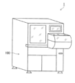
- FIG. 1 is a schematic overall external view of an automatic analyzer according to an embodiment of the present invention
- FIG. 2 is a block diagram showing a schematic configuration of the automatic analyzer of FIG. 1
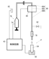
- FIG. FIG. 2 is a schematic diagram showing the main configuration of the features of the present invention of the automatic analyzer of FIG. 1
- FIG. 4 is a schematic diagram showing an embodiment of the configuration of FIG. 3;
- FIG. 1 is a schematic overall external view of an automatic analyzer 1 of this embodiment
- FIG. 2 is a block diagram showing a schematic internal configuration of the automatic analyzer 1 of FIG.
- the automatic analyzer 1 of the present embodiment includes a reaction container installation section 40 holding a reaction container 54 into which a sample collected from a person such as blood or urine is dispensed, and a reagent container 74.
- the reaction container 54 the reagent supplied from the reagent supply unit 70 to the reaction container 54 is reacted with the specimen in the reaction container 54, and the reaction process or result is detected by the detector 64.
- the automatic analyzer 1 of this embodiment has its outer frame formed by a housing 100, and a sample processing space is formed in the upper part of the housing 100 (see FIG. 1).
- the automatic analyzer 1 comprises a control unit 10, a measurement unit 30, and a display/operation unit.
- a touch screen 190 is provided as a display/operation unit.
- the control unit 10 controls the overall operation of the automatic analyzer 1.
- the control unit 10 is configured by, for example, a personal computer (PC).
- the control unit 10 includes a Central Processing Unit (CPU) 12, a Random Access Memory (RAM) 14, a Read Only Memory (ROM) 16, a storage 18, and a communication interface (I/F ) 20.
- the CPU 12 performs various signal processing and the like.
- the RAM 14 functions as a main storage device for the CPU 12 .
- the RAM 14 for example, Dynamic RAM (DRAM), Static RAM (SRAM), etc. can be used.
- the ROM 16 records various boot programs and the like.
- For the storage 18, for example, a Hard Disk Drive (HDD), Solid State Drive (SSD), etc. can be used.
- the control unit 10 communicates with external devices such as the measurement unit 30 and the touch screen 190 via the communication I/F 20 .
- the touch screen 190 includes a display device 192 as a display unit and, for example, a touch panel 194 as an operation unit or the like.
- Display device 192 may include, for example, a liquid crystal display (LCD) or an organic EL display.
- the display device 192 displays various screens under the control of the control unit 10 . This screen may include various screens such as a display screen related to reagent amounts, an operation screen of the automatic analyzer 1, a screen showing measurement results, and a screen showing analysis results.
- a touch panel 194 is provided on the display device 192 .
- the touch panel 194 acquires input from the user and transmits the acquired input information to the control unit 10 .
- the control unit 10 may be connected to other devices such as printers, handy code readers, host computers, etc. via the communication I/F 20 .
- the measurement unit 30 includes a control circuit 42 as a control section, a data processing circuit 44, a reaction container 54, a detector 64, a sample container 72, a reagent container 74, a sample nozzle 76, and a liquid reagent. and a reagent nozzle 78 as a dispensing nozzle for dispensing into the container 54 .
- a control circuit 42 as a control section
- a data processing circuit 44 includes a liquid reagent. and a reagent nozzle 78 as a dispensing nozzle for dispensing into the container 54 .
- the control circuit 42 controls the operation of each section of the measurement unit 30 based on commands from the control unit 10 .
- the control circuit 42 is connected to the data processing circuit 44, the detector 64, the sample nozzle 76, the reagent nozzle 78, etc., and controls the operation of each part.
- the data processing circuit 44 is connected to the detector 64 and obtains detection results from the detector 64 .
- the data processing circuit 44 performs various types of processing on the acquired detection results and outputs the processing results.
- the processing performed by the data processing circuit 44 may include, for example, A/D conversion processing for changing the format of the data output from the detector 64 into a format that can be processed by the control unit 10 .
- the control circuit 42 and data processing circuit 44 may include, for example, a CPU, an Application Specific Integrated Circuit (ASIC), or a Field Programmable Gate Array (FPGA).
- the control circuit 42 and the data processing circuit 44 may each be configured by one integrated circuit or the like, or may be configured by combining a plurality of integrated circuits or the like. Also, the control circuit 42 and the data processing circuit 44 may be configured by one integrated circuit or the like.
- the operations of the control circuit 42 and the data processing circuit 44 can be performed according to a program recorded in a storage device or a recording area in the circuit, for example.
- the sample container 72 contains, for example, a sample obtained from blood collected from a patient.
- Various reagents used for measurement are stored in the reagent container 74 .
- Any number of specimen containers 72 and reagent containers 74 may be provided. Since there are usually multiple types of reagents used for analysis, there are generally multiple reagent containers 74 .
- the sample nozzle 76 dispenses the sample contained in the sample container 72 into the reaction container 54 under the control of the control circuit 42 .
- the reagent nozzle 78 dispenses the reagent supplied from the reagent container 74 in the reagent supply section 70 through the reagent channel 60 into the reaction container 54 under the control of the control circuit 42 (this will be described later). Any number of sample nozzles 76 and reagent nozzles 78 may be used.
- the control unit 10 performs various calculations based on the data acquired from the measurement unit 30. This calculation includes calculation of the reaction amount of the mixed solution, quantitative calculation of the substance amount and activity value of the measurement target substance in the specimen based on the reaction amount, and the like. Some or all of these operations may be performed by the data processing circuit 44 .
- the reagent nozzle (for example, SUS nozzle) 78 serving as a dispensing nozzle for dispensing a liquid reagent into the reaction container 54 is connected to the reagent supply section 70 via the reagent channel 60 made of, for example, a resin pipe. is connected to a reagent container (here, a syringe) 74 .
- a temperature control section 80 is provided which is composed of a heater (with an aluminum block housing, for example) that partially controls the temperature of the reagent channel 60 .
- the measurement unit 30 of the automatic analyzer 1 also has a temperature measurement section 82 including a temperature sensor for measuring the environmental temperature.
- the operation of the temperature control section 80 and the reagent container 74 consisting of the syringe is controlled by the control circuit 42 , and the temperature information from the temperature measurement section 82 is input to the control circuit 42 .
- the temperature control unit 80 is controlled to be kept at a constant heating temperature (for example, a set temperature of 33° C. to 60° C.), and the reagent stays in the channel 60C in the temperature control unit 80. or the upstream channel 60A of the reagent channel 60 positioned upstream of the temperature control unit 80 and the downstream of the temperature control unit 80.
- the temperature is not controlled in the downstream channel 60B of the reagent channel 60 located on the side.
- the reaction container 54 is moved by a moving body 83 such as a rotary table to a predetermined discharge position P at which the reagent is to be discharged into the reaction container 54 through the reagent nozzle 78 .
- this moving body 83 is also controlled by the control circuit 42 .
- the operation of discharging the reagent to the reaction container 54 (the operation of supplying the reagent through the reagent channel 60) is performed at a cycle of 36 seconds. is positioned at the ejection position P by the moving body 83 . Therefore, correspondingly, the temperature of the reagent in the reagent supply system shown in FIG. 3 may also fluctuate with a period of 36 seconds.
- reaction reagent discharge for example, until 34 seconds have elapsed since the previous discharge of the reagent into the reaction container 54 (such reagent discharge is hereinafter referred to as reaction reagent discharge). is in a reagent supply standby state, during which the temperature of the reagent 90a in the upstream channel 60A and the downstream channel 60B of the temperature control unit 80 of the reagent channel 60 is lower than the temperature controlled at the time of discharge of the reaction reagent. can. Then, when 34 seconds have elapsed since the previous ejection of the reaction reagent, the reagent container 74, which is a syringe, is actuated to cause the reagent to flow through the reagent channel 60.
- FIG. 4 the reagent present in the upstream channel 60A of the reagent channel 60 and the channel 60C in the temperature control unit 80 in the reagent supply standby state is warmed. After being heated through the adjusting section 80, the reagent moves into the downstream channel 60B (of course, the reagent existing in the downstream channel 60B is discharged out of the reagent channel 60 through the reagent nozzle 78). is done).
- the reagent 90b that has been temperature-controlled (heated) and moved into the downstream channel 60B is indicated by oblique lines. Then, after 2 seconds have passed (that is, 36 seconds after the previous reaction reagent was discharged), the next reaction reagent is discharged through the reagent nozzle 78 into the reaction container 54 which has been moved to the discharge position P. done.
- the control circuit 42 controls the environmental temperature measured by the temperature measuring unit 82 and/or the set target temperature of the reagent to be ejected into the reaction container 54 .
- the downstream side flow channel 60B of the reagent flow channel 60 on the downstream side of the temperature control unit 80 in the reagent supply standby state Prior to the start of the reaction reagent discharging operation for discharging the reagent into the reaction container 54 through the reagent nozzle 78 based on the temperature, the downstream side flow channel 60B of the reagent flow channel 60 on the downstream side of the temperature control unit 80 in the reagent supply standby state.
- the reagent By discharging part or all of the existing reagent, which is a reagent that has already existed inside and within the reagent nozzle 78, to the outside of the reagent channel 60 without discharging it into the reaction container 54, the reagent discharged into the reaction container 54 to control the ratio of the amount of existing reagent to the total amount of
- the operation of discharging part or all of the existing reagent out of the reagent channel 60 without discharging it into the reaction container 54 is performed by moving the reaction container 54 with respect to the discharge position P in this embodiment involving the moving body 83. This is done by controlling the operation timing of the movable body 83 to be moved by the control circuit 42 (that is, until the reaction container 54 is positioned at the discharge position P facing the reagent nozzle 78, the existing reagent is discharged through the reagent nozzle 78). is ejected out of the reagent flow path 60), but other embodiments allow ejection of the reagent out of the reagent flow path 60 upstream of the reagent nozzle 78, e.g.
- the operation timing is controlled so that the existing reagent is discharged out of the reagent channel 60 through the reagent nozzle 78 to the waste liquid portion (not shown) at a discharge position (not shown) different from the discharge position P of the reagent nozzle 78. It may be done by controlling by circuit 42 .
- the temperature control reagent that is present in the upstream channel 60A of the temperature control unit 80 and the channel 60C in the temperature control unit 80 and that has flowed into the downstream channel 60B after being heated by the temperature control unit (reagent indicated by diagonal lines) portion) 90b are mixed in the downstream channel 60B, the reaction vessel 54 is moved to the discharge position P at a predetermined timing as indicated by the dashed line in the state shown in (b) of FIG.
- the reaction vessel 54 is controlled to move to the discharge position P at a predetermined timing in the state shown in FIG.
- Such ratio control is performed for each reaction reagent discharge operation.
- Such ratio control is based on a control table as shown in Table 1 below, which defines the amount of the reagent discharged out of the reagent flow channel 60 before the start of the reaction reagent discharging operation in association with the environmental temperature. may be performed on the basis of In this control table, the total amount of reagent discharged into the reaction container 54 (reaction reagent discharge amount) Q is constant at 300 ⁇ L, and the reagent supply waiting state is set to the downstream side of the reagent flow path 60 downstream of the temperature control unit 80 .
- the amount of the reagent discharged out of the reagent channel 60 before the start of the reaction reagent discharge operation (amount of waste reagent discharged; maximum 350 ⁇ L) q, the amount of the existing reagent after discharge of the waste reagent included in Q discharged to the reaction container 54
- the quantity Q2 is defined in association with the environmental temperature (in this case, the temperature inside the device) T.
- the above-described ratio controlled by the control circuit 42 that is, the ratio Q2 of the amount Q2 of the existing reagent after discharging the waste reagent to the total amount of reagent discharged into the reaction container 54 (reaction reagent discharge amount 300 ⁇ L) Q2 /Q is 0 when the environmental temperature is 21.9° C. or lower. That is, all of the existing reagent 90 a is discharged out of the reagent channel 60 without being discharged into the reaction container 54 . In other words, the reaction container 54 is controlled to be moved to the discharge position P at a predetermined timing in the state of FIG. .
- the ratio gradually increases, and only part of the existing reagent 90 a is discharged out of the reagent channel 60 without being discharged into the reaction container 54 .
- the reaction container 54 or the reagent nozzle 78 is moved to the ejection position P at a predetermined timing in the state of FIG. controlled as Then, when the environmental temperature exceeds 30° C., the ratio continues to increase, but along with this, the waste reagent discharge amount q becomes zero. That is, the reaction container 54 or the reagent nozzle 78 is controlled to move to the discharge position P in the state of FIG.
- the temperature control reagent is dispensed into the reaction vessel by the amount exceeding ).
- the control table in Table 1 shows the environmental temperature T in increments of 1.0° C. for the sake of convenience, in practice, the waste reagent discharge amount q and the like are defined based on further subdivided temperature data. ing.
- the reagent is discharged into the reaction container 54 based on the environmental temperature and/or the set target temperature of the reagent.
- the existing reagent By discharging part or all of the existing reagent that has already existed in the reagent channel 60 and the reagent nozzle 78 on the downstream side of the temperature control unit 80 to the outside of the reagent channel 60 before the start of the operation, Since the ratio of the amount of the existing reagent to the total amount of the reagent discharged into the reaction container 54 is controlled, the existing reagent whose temperature is generally lower than the temperature of the reagent whose temperature is controlled by the temperature control unit 80 into the reaction container 54 (the mixing ratio of the existing reagent and the temperature control reagent) is controlled based on the environmental temperature (based on the temperature of the existing reagent).
- the loss of the reagent is minimized and the output of the temperature control section 80 is kept constant.
- the temperature of the reagent discharged into the reaction container 54 can be quickly set to the target temperature and stabilized.
- a special mechanism such as a mechanism for finely controlling the set temperature of the temperature control unit 80 is not required (the device does not require a complicated structure).
- the temperature of the reagent discharged into the reaction container 54 can be stabilized easily and inexpensively regardless of the temperature of the environment including the inside of the apparatus 1, and the temperature of the reagent can be stabilized.
- Accurate temperature control can be performed by setting the target temperature so that there is no variation, and accurate measurement values can be obtained.
- the present invention is not limited to the above-described embodiment, and can be modified in various ways without departing from the scope of the invention.
- the configurations of the temperature control section, reagent container, reagent nozzle, etc. are not limited to the configurations described above. Further, part or all of the above-described embodiments may be combined without departing from the gist of the present invention, or part of the configuration may be omitted from one of the above-described embodiments. good too.
- control circuit control unit
- control circuit control unit
- reagent channel 70 reagent supply section 78 reagent nozzle (dispensing nozzle) 80 temperature control unit 82 temperature measurement unit
Landscapes
- Physics & Mathematics (AREA)
- Health & Medical Sciences (AREA)
- Life Sciences & Earth Sciences (AREA)
- Chemical & Material Sciences (AREA)
- Analytical Chemistry (AREA)
- Biochemistry (AREA)
- General Health & Medical Sciences (AREA)
- General Physics & Mathematics (AREA)
- Immunology (AREA)
- Pathology (AREA)
- Automatic Analysis And Handling Materials Therefor (AREA)
Priority Applications (1)
| Application Number | Priority Date | Filing Date | Title |
|---|---|---|---|
| JP2023571054A JPWO2023127878A1 (https=) | 2021-12-28 | 2022-12-27 |
Applications Claiming Priority (2)
| Application Number | Priority Date | Filing Date | Title |
|---|---|---|---|
| JP2021-214147 | 2021-12-28 | ||
| JP2021214147 | 2021-12-28 |
Publications (1)
| Publication Number | Publication Date |
|---|---|
| WO2023127878A1 true WO2023127878A1 (ja) | 2023-07-06 |
Family
ID=86999073
Family Applications (1)
| Application Number | Title | Priority Date | Filing Date |
|---|---|---|---|
| PCT/JP2022/048198 Ceased WO2023127878A1 (ja) | 2021-12-28 | 2022-12-27 | 自動分析装置及び自動分析装置の試薬分注方法 |
Country Status (2)
| Country | Link |
|---|---|
| JP (1) | JPWO2023127878A1 (https=) |
| WO (1) | WO2023127878A1 (https=) |
Citations (13)
| Publication number | Priority date | Publication date | Assignee | Title |
|---|---|---|---|---|
| JPS57132063A (en) * | 1981-02-10 | 1982-08-16 | Olympus Optical Co Ltd | Method for automatic chemical analysis |
| US4367198A (en) * | 1981-06-19 | 1983-01-04 | Medical Laboratory Automation, Inc. | Reagent reservoir system for use in testing apparatus |
| JPS6023725Y2 (ja) * | 1977-11-10 | 1985-07-15 | 株式会社島津製作所 | 試薬分注装置 |
| JP2012159392A (ja) * | 2011-01-31 | 2012-08-23 | Sysmex Corp | 分析装置及び分析方法 |
| JP2014092427A (ja) * | 2012-11-02 | 2014-05-19 | Hitachi High-Technologies Corp | 自動分析装置 |
| JP2016166774A (ja) * | 2015-03-09 | 2016-09-15 | 株式会社島津製作所 | 分注装置及びこれを備えた分析装置、並びに、分注方法 |
| JP2018036080A (ja) * | 2016-08-30 | 2018-03-08 | 株式会社日立ハイテクノロジーズ | 自動分析装置 |
| WO2018047545A1 (ja) * | 2016-09-08 | 2018-03-15 | 株式会社 日立ハイテクノロジーズ | 自動分析装置 |
| JP2018146374A (ja) * | 2017-03-06 | 2018-09-20 | テラメックス株式会社 | 温調システム |
| JP2019074412A (ja) * | 2017-10-16 | 2019-05-16 | キヤノンメディカルシステムズ株式会社 | 分注制御装置、分注制御方法及び分注制御プログラム |
| WO2019194096A1 (ja) * | 2018-04-05 | 2019-10-10 | コニカミノルタ株式会社 | 温調システム及び温調方法 |
| JP2020041875A (ja) * | 2018-09-10 | 2020-03-19 | 株式会社日立ハイテクノロジーズ | 自動分析装置 |
| JP2020106424A (ja) * | 2018-12-27 | 2020-07-09 | 株式会社日立ハイテク | 自動分析装置 |
-
2022
- 2022-12-27 WO PCT/JP2022/048198 patent/WO2023127878A1/ja not_active Ceased
- 2022-12-27 JP JP2023571054A patent/JPWO2023127878A1/ja active Pending
Patent Citations (13)
| Publication number | Priority date | Publication date | Assignee | Title |
|---|---|---|---|---|
| JPS6023725Y2 (ja) * | 1977-11-10 | 1985-07-15 | 株式会社島津製作所 | 試薬分注装置 |
| JPS57132063A (en) * | 1981-02-10 | 1982-08-16 | Olympus Optical Co Ltd | Method for automatic chemical analysis |
| US4367198A (en) * | 1981-06-19 | 1983-01-04 | Medical Laboratory Automation, Inc. | Reagent reservoir system for use in testing apparatus |
| JP2012159392A (ja) * | 2011-01-31 | 2012-08-23 | Sysmex Corp | 分析装置及び分析方法 |
| JP2014092427A (ja) * | 2012-11-02 | 2014-05-19 | Hitachi High-Technologies Corp | 自動分析装置 |
| JP2016166774A (ja) * | 2015-03-09 | 2016-09-15 | 株式会社島津製作所 | 分注装置及びこれを備えた分析装置、並びに、分注方法 |
| JP2018036080A (ja) * | 2016-08-30 | 2018-03-08 | 株式会社日立ハイテクノロジーズ | 自動分析装置 |
| WO2018047545A1 (ja) * | 2016-09-08 | 2018-03-15 | 株式会社 日立ハイテクノロジーズ | 自動分析装置 |
| JP2018146374A (ja) * | 2017-03-06 | 2018-09-20 | テラメックス株式会社 | 温調システム |
| JP2019074412A (ja) * | 2017-10-16 | 2019-05-16 | キヤノンメディカルシステムズ株式会社 | 分注制御装置、分注制御方法及び分注制御プログラム |
| WO2019194096A1 (ja) * | 2018-04-05 | 2019-10-10 | コニカミノルタ株式会社 | 温調システム及び温調方法 |
| JP2020041875A (ja) * | 2018-09-10 | 2020-03-19 | 株式会社日立ハイテクノロジーズ | 自動分析装置 |
| JP2020106424A (ja) * | 2018-12-27 | 2020-07-09 | 株式会社日立ハイテク | 自動分析装置 |
Also Published As
| Publication number | Publication date |
|---|---|
| JPWO2023127878A1 (https=) | 2023-07-06 |
Similar Documents
| Publication | Publication Date | Title |
|---|---|---|
| JP6746188B2 (ja) | 自動分析装置 | |
| EP3511720B1 (en) | Automatic analyzer | |
| US5051238A (en) | Automatic analyzing system | |
| CN104854459B (zh) | 自动分析装置 | |
| CN103261876B (zh) | 自动分析装置 | |
| CN104871007A (zh) | 自动分析装置 | |
| CA1057974A (en) | Apparatus and method for batch-type analysis of liquid samples | |
| JP6567873B2 (ja) | 自動分析装置 | |
| CN110031643A (zh) | 自动分析装置 | |
| JP5097466B2 (ja) | 自動分析装置 | |
| WO2023127878A1 (ja) | 自動分析装置及び自動分析装置の試薬分注方法 | |
| JP5952180B2 (ja) | 自動分析装置、プログラムおよび記録媒体ならびに検体の自動分析方法 | |
| US20210148943A1 (en) | Automatic analysis device | |
| US6679103B1 (en) | Continuous flow moisture analyzer for determining moisture content in liquid sample material | |
| JP4635138B2 (ja) | 特定成分の分析方法 | |
| JP7051495B2 (ja) | 自動分析装置、及び分注方法 | |
| JPWO2017033648A1 (ja) | 自動分析装置及び自動分析システム | |
| JP7197723B2 (ja) | 試薬管理方法 | |
| JP3983872B2 (ja) | 自動分析装置 | |
| JP4705182B2 (ja) | 特定成分の分析装置 | |
| EP4506694A1 (en) | Automatic analysis device | |
| CN113433330A (zh) | 一种样本分析仪及其稳定反应液温度的方法 | |
| JP2022026449A (ja) | 自動分析装置 | |
| JP2003114238A (ja) | 自動化バイオセンサ装置および自動化バイオセンサシステム | |
| US20240192245A1 (en) | Automatic analysis device and abnormality detection method |
Legal Events
| Date | Code | Title | Description |
|---|---|---|---|
| 121 | Ep: the epo has been informed by wipo that ep was designated in this application |
Ref document number: 22916100 Country of ref document: EP Kind code of ref document: A1 |
|
| WWE | Wipo information: entry into national phase |
Ref document number: 2023571054 Country of ref document: JP |
|
| NENP | Non-entry into the national phase |
Ref country code: DE |
|
| 122 | Ep: pct application non-entry in european phase |
Ref document number: 22916100 Country of ref document: EP Kind code of ref document: A1 |