WO2023127878A1 - Automatic analysis device and reagent dispensing method of automatic analysis device - Google Patents
Automatic analysis device and reagent dispensing method of automatic analysis device Download PDFInfo
- Publication number
- WO2023127878A1 WO2023127878A1 PCT/JP2022/048198 JP2022048198W WO2023127878A1 WO 2023127878 A1 WO2023127878 A1 WO 2023127878A1 JP 2022048198 W JP2022048198 W JP 2022048198W WO 2023127878 A1 WO2023127878 A1 WO 2023127878A1
- Authority
- WO
- WIPO (PCT)
- Prior art keywords
- reagent
- temperature
- reaction container
- channel
- control unit
- Prior art date
Links
- 239000003153 chemical reaction reagent Substances 0.000 title claims abstract description 282
- 238000004458 analytical method Methods 0.000 title claims abstract description 15
- 238000000034 method Methods 0.000 title claims abstract description 10
- 238000006243 chemical reaction Methods 0.000 claims abstract description 110
- 230000007613 environmental effect Effects 0.000 claims abstract description 32
- 238000007599 discharging Methods 0.000 claims abstract description 27
- 238000005259 measurement Methods 0.000 claims description 23
- 239000007788 liquid Substances 0.000 claims description 8
- 238000010438 heat treatment Methods 0.000 claims description 5
- 238000009529 body temperature measurement Methods 0.000 abstract description 5
- 238000012545 processing Methods 0.000 description 18
- 239000000523 sample Substances 0.000 description 17
- 238000011144 upstream manufacturing Methods 0.000 description 6
- 239000002699 waste material Substances 0.000 description 6
- 238000012360 testing method Methods 0.000 description 5
- 239000008280 blood Substances 0.000 description 4
- 210000004369 blood Anatomy 0.000 description 4
- 238000010586 diagram Methods 0.000 description 4
- 238000004891 communication Methods 0.000 description 3
- 210000002700 urine Anatomy 0.000 description 3
- 238000001514 detection method Methods 0.000 description 2
- 230000000694 effects Effects 0.000 description 2
- 230000006870 function Effects 0.000 description 2
- 239000000126 substance Substances 0.000 description 2
- 238000002835 absorbance Methods 0.000 description 1
- XAGFODPZIPBFFR-UHFFFAOYSA-N aluminium Chemical compound [Al] XAGFODPZIPBFFR-UHFFFAOYSA-N 0.000 description 1
- 229910052782 aluminium Inorganic materials 0.000 description 1
- 239000012472 biological sample Substances 0.000 description 1
- 230000023555 blood coagulation Effects 0.000 description 1
- 238000001816 cooling Methods 0.000 description 1
- 238000003018 immunoassay Methods 0.000 description 1
- 238000009434 installation Methods 0.000 description 1
- 239000004973 liquid crystal related substance Substances 0.000 description 1
- 238000004020 luminiscence type Methods 0.000 description 1
- 239000011259 mixed solution Substances 0.000 description 1
- 239000000203 mixture Substances 0.000 description 1
- 239000012070 reactive reagent Substances 0.000 description 1
- 239000011347 resin Substances 0.000 description 1
- 229920005989 resin Polymers 0.000 description 1
- 239000007787 solid Substances 0.000 description 1
- 239000000243 solution Substances 0.000 description 1
- 230000000087 stabilizing effect Effects 0.000 description 1
- 230000003068 static effect Effects 0.000 description 1
- 239000013076 target substance Substances 0.000 description 1
Images


Classifications
-
- G—PHYSICS
- G01—MEASURING; TESTING
- G01N—INVESTIGATING OR ANALYSING MATERIALS BY DETERMINING THEIR CHEMICAL OR PHYSICAL PROPERTIES
- G01N35/00—Automatic analysis not limited to methods or materials provided for in any single one of groups G01N1/00 - G01N33/00; Handling materials therefor
-
- G—PHYSICS
- G01—MEASURING; TESTING
- G01N—INVESTIGATING OR ANALYSING MATERIALS BY DETERMINING THEIR CHEMICAL OR PHYSICAL PROPERTIES
- G01N35/00—Automatic analysis not limited to methods or materials provided for in any single one of groups G01N1/00 - G01N33/00; Handling materials therefor
- G01N35/10—Devices for transferring samples or any liquids to, in, or from, the analysis apparatus, e.g. suction devices, injection devices
Definitions
- the present invention is an automatic analysis that can obtain measurement information on various analysis items by reacting a sample (specimen) such as blood or urine with various reagents and measuring the reaction process, reaction progress, reaction result, etc.
- the present invention relates to a reagent dispensing method for an apparatus and an automatic analyzer.
- Various analyses such as blood coagulation analyzers and analyzers using immunoassay, are performed by reacting biological samples such as blood and urine with various reagents and measuring the reaction process, reaction progress, reaction results, etc.
- Various types of automated analyzers capable of obtaining measurement information regarding test items have been known in the past.
- Various measurements and analyzes are performed by dispensing and mixing reagents according to test items into a specimen (see, for example, Patent Document 1).
- test values such as the concentration and activity value of the substance to be measured are obtained.
- the present invention has been made in view of the above-described problems, and is an automatic analysis system capable of stabilizing the temperature of a reagent discharged into a reaction container simply and inexpensively regardless of the temperature of the environment including the inside of the apparatus.
- the purpose is to provide an apparatus.
- the present invention provides an automatic analyzer for obtaining measurement information on a predetermined analysis item by reacting a sample with a reagent and measuring the progress and/or result of the reaction, comprising: into a reaction container, a reagent channel for transferring the reagent from a reagent supply unit to the dispensing nozzle, a temperature control unit for partially controlling the temperature of the reagent channel, and an environment a temperature measuring unit for measuring temperature; and based on the environmental temperature measured by the temperature measuring unit and/or the set target temperature of the reagent to be discharged into the reaction container, the reaction container is detected through the dispensing nozzle.
- the existing reagent which is a reagent that has already existed in the reagent flow channel and the dispensing nozzle on the downstream side of the temperature control unit, before the operation of discharging the reagent to the reaction is started.
- a control unit for controlling the ratio of the amount of the existing reagent to the total amount of the reagent to be discharged into the reaction container by discharging out of the reagent channel without discharging into the container.
- the automatic analyzer configured as described above, based on the environmental temperature and/or the set target temperature of the reagent, before the start of the operation of discharging the reagent into the reaction container, the reagent flow path on the downstream side of the temperature control unit By ejecting part or all of the existing reagent already existing inside and inside the dispensing nozzle to the outside of the reagent channel, the ratio of the amount of the existing reagent to the total amount of reagent ejected into the reaction container is controlled.
- the discharge ratio of the existing reagent which is generally lower in temperature than the temperature-controlled reagent by the temperature control unit, into the reaction container (the mixing ratio of the existing reagent and the temperature-controlled reagent) It will be controlled based on the temperature (based on the temperature of the existing reagent).
- the loss of the reagent is minimized and the output of the temperature control unit is kept constant.
- the temperature of the reagent discharged into the reaction container can be quickly set to the target temperature and stabilized. As a result, there is no need for a special mechanism such as a mechanism for finely controlling the set temperature of the temperature control unit (the device does not require a complicated structure).
- the temperature of the reagent discharged into the reaction container can be stabilized easily and inexpensively regardless of the temperature of the environment including the inside of the device, and the temperature of the reagent can be kept at the target temperature.
- Accurate temperature control which is set and controlled so that there is no variation, can be performed to obtain accurate measurement values.
- the "temperature control section” may be of any form as long as it adjusts the temperature by heating the reagent with a heater or the like. Moreover, in the above configuration, “temperature control” includes heating, heat retention, and cooling.
- the "ratio" includes 0. That is, depending on the environmental temperature (for example, when the environmental temperature is excessively low), the existing reagent may not be discharged entirely into the reaction container, but may be discharged out of the reagent channel. The ratio of the amount of existing reagent to the total amount of discharged reagent becomes zero.
- the “environmental temperature” refers to the temperature of the environment surrounding the operating area of the device, including the internal temperature of the device and the temperature of the outside air.
- control unit controls a function unit capable of realizing such a discharge operation.
- control includes controlling the operation timing of a drive unit (functional unit) for moving the dispensing nozzle or the reaction container with respect to a discharge position for discharging the reagent through the dispensing nozzle into the reaction container; Examples include, but are not limited to, a control unit controlling the operation of an on-off valve that enables the reagent to be discharged out of the channel.
- control unit controls the ratio for each operation of discharging the reagent into the reaction container through the dispensing nozzle. According to this, a reagent at a stable target temperature can be dispensed for each sample, accurate measurement values can be obtained for each sample, and it is possible to respond well to short-term, sudden changes in environmental temperature. good reagent temperature control can be realized.
- control unit controls the ratio based on a control table that defines at least the amount of the reagent to be discharged out of the reagent channel before starting the operation of discharging the reagent into the reaction container in association with the environmental temperature. preferably. According to this, it is possible to realize uniform temperature control and enable easy and accurate temperature control.
- the present invention provides a dispensing nozzle for dispensing a liquid reagent into a reaction vessel, a reagent channel for transferring the reagent from a reagent supply unit to the dispensing nozzle, and a
- an automatic analyzer comprising a temperature control section and a temperature measurement section, the reagent is dispensed into the reaction container at a predetermined target temperature, the specimen is reacted with the reagent, and the progress and/or reaction result of the reaction is measured.
- a reagent dispensing method for an automatic analyzer for obtaining measurement information on a predetermined analysis item by A discharge amount of the reagent present in the reagent flow path downstream of the temperature control unit and in the dispensing nozzle to the outside of the reagent flow path is calculated based on the environmental temperature and the target temperature. 1 step; A second step of discharging the calculated discharge amount of the reagent from the dispensing nozzle to a place other than the reaction container by passing the reagent through the reagent channel while heating the reagent by the temperature control unit. and, a third step of subsequently dispensing the reagent into the reaction vessel; characterized by comprising
- the existing reagent that has not been temperature-controlled (existing reagent) is discharged out of the reagent flow channel, and the ratio of the amount of the existing reagent to the total amount of the reagent discharged into the reaction container is controlled, so that the temperature of the reagent is controlled by the temperature control unit. It is possible to adjust the discharge rate (the mixing ratio of the existing reagent and the temperature control reagent) of the existing reagent whose temperature is generally lowered into the reaction container based on the environmental temperature.
- the loss of the reagent is minimized and the output of the temperature control unit is kept constant.
- the temperature of the reagent discharged into the reaction container can be quickly set to the target temperature and stabilized.
- an automatic analyzer and a dispensing method for the automatic analyzer that can easily and inexpensively stabilize the temperature of the reagent discharged into the reaction container regardless of the temperature of the environment including the inside of the device. can do.
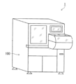
- FIG. 1 is a schematic overall external view of an automatic analyzer according to an embodiment of the present invention
- FIG. 2 is a block diagram showing a schematic configuration of the automatic analyzer of FIG. 1
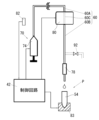
- FIG. FIG. 2 is a schematic diagram showing the main configuration of the features of the present invention of the automatic analyzer of FIG. 1
- FIG. 4 is a schematic diagram showing an embodiment of the configuration of FIG. 3;
- FIG. 1 is a schematic overall external view of an automatic analyzer 1 of this embodiment
- FIG. 2 is a block diagram showing a schematic internal configuration of the automatic analyzer 1 of FIG.
- the automatic analyzer 1 of the present embodiment includes a reaction container installation section 40 holding a reaction container 54 into which a sample collected from a person such as blood or urine is dispensed, and a reagent container 74.
- the reaction container 54 the reagent supplied from the reagent supply unit 70 to the reaction container 54 is reacted with the specimen in the reaction container 54, and the reaction process or result is detected by the detector 64.
- the automatic analyzer 1 of this embodiment has its outer frame formed by a housing 100, and a sample processing space is formed in the upper part of the housing 100 (see FIG. 1).
- the automatic analyzer 1 comprises a control unit 10, a measurement unit 30, and a display/operation unit.
- a touch screen 190 is provided as a display/operation unit.
- the control unit 10 controls the overall operation of the automatic analyzer 1.
- the control unit 10 is configured by, for example, a personal computer (PC).
- the control unit 10 includes a Central Processing Unit (CPU) 12, a Random Access Memory (RAM) 14, a Read Only Memory (ROM) 16, a storage 18, and a communication interface (I/F ) 20.
- the CPU 12 performs various signal processing and the like.
- the RAM 14 functions as a main storage device for the CPU 12 .
- the RAM 14 for example, Dynamic RAM (DRAM), Static RAM (SRAM), etc. can be used.
- the ROM 16 records various boot programs and the like.
- For the storage 18, for example, a Hard Disk Drive (HDD), Solid State Drive (SSD), etc. can be used.
- the control unit 10 communicates with external devices such as the measurement unit 30 and the touch screen 190 via the communication I/F 20 .
- the touch screen 190 includes a display device 192 as a display unit and, for example, a touch panel 194 as an operation unit or the like.
- Display device 192 may include, for example, a liquid crystal display (LCD) or an organic EL display.
- the display device 192 displays various screens under the control of the control unit 10 . This screen may include various screens such as a display screen related to reagent amounts, an operation screen of the automatic analyzer 1, a screen showing measurement results, and a screen showing analysis results.
- a touch panel 194 is provided on the display device 192 .
- the touch panel 194 acquires input from the user and transmits the acquired input information to the control unit 10 .
- the control unit 10 may be connected to other devices such as printers, handy code readers, host computers, etc. via the communication I/F 20 .
- the measurement unit 30 includes a control circuit 42 as a control section, a data processing circuit 44, a reaction container 54, a detector 64, a sample container 72, a reagent container 74, a sample nozzle 76, and a liquid reagent. and a reagent nozzle 78 as a dispensing nozzle for dispensing into the container 54 .
- a control circuit 42 as a control section
- a data processing circuit 44 includes a liquid reagent. and a reagent nozzle 78 as a dispensing nozzle for dispensing into the container 54 .
- the control circuit 42 controls the operation of each section of the measurement unit 30 based on commands from the control unit 10 .
- the control circuit 42 is connected to the data processing circuit 44, the detector 64, the sample nozzle 76, the reagent nozzle 78, etc., and controls the operation of each part.
- the data processing circuit 44 is connected to the detector 64 and obtains detection results from the detector 64 .
- the data processing circuit 44 performs various types of processing on the acquired detection results and outputs the processing results.
- the processing performed by the data processing circuit 44 may include, for example, A/D conversion processing for changing the format of the data output from the detector 64 into a format that can be processed by the control unit 10 .
- the control circuit 42 and data processing circuit 44 may include, for example, a CPU, an Application Specific Integrated Circuit (ASIC), or a Field Programmable Gate Array (FPGA).
- the control circuit 42 and the data processing circuit 44 may each be configured by one integrated circuit or the like, or may be configured by combining a plurality of integrated circuits or the like. Also, the control circuit 42 and the data processing circuit 44 may be configured by one integrated circuit or the like.
- the operations of the control circuit 42 and the data processing circuit 44 can be performed according to a program recorded in a storage device or a recording area in the circuit, for example.
- the sample container 72 contains, for example, a sample obtained from blood collected from a patient.
- Various reagents used for measurement are stored in the reagent container 74 .
- Any number of specimen containers 72 and reagent containers 74 may be provided. Since there are usually multiple types of reagents used for analysis, there are generally multiple reagent containers 74 .
- the sample nozzle 76 dispenses the sample contained in the sample container 72 into the reaction container 54 under the control of the control circuit 42 .
- the reagent nozzle 78 dispenses the reagent supplied from the reagent container 74 in the reagent supply section 70 through the reagent channel 60 into the reaction container 54 under the control of the control circuit 42 (this will be described later). Any number of sample nozzles 76 and reagent nozzles 78 may be used.
- the control unit 10 performs various calculations based on the data acquired from the measurement unit 30. This calculation includes calculation of the reaction amount of the mixed solution, quantitative calculation of the substance amount and activity value of the measurement target substance in the specimen based on the reaction amount, and the like. Some or all of these operations may be performed by the data processing circuit 44 .
- the reagent nozzle (for example, SUS nozzle) 78 serving as a dispensing nozzle for dispensing a liquid reagent into the reaction container 54 is connected to the reagent supply section 70 via the reagent channel 60 made of, for example, a resin pipe. is connected to a reagent container (here, a syringe) 74 .
- a temperature control section 80 is provided which is composed of a heater (with an aluminum block housing, for example) that partially controls the temperature of the reagent channel 60 .
- the measurement unit 30 of the automatic analyzer 1 also has a temperature measurement section 82 including a temperature sensor for measuring the environmental temperature.
- the operation of the temperature control section 80 and the reagent container 74 consisting of the syringe is controlled by the control circuit 42 , and the temperature information from the temperature measurement section 82 is input to the control circuit 42 .
- the temperature control unit 80 is controlled to be kept at a constant heating temperature (for example, a set temperature of 33° C. to 60° C.), and the reagent stays in the channel 60C in the temperature control unit 80. or the upstream channel 60A of the reagent channel 60 positioned upstream of the temperature control unit 80 and the downstream of the temperature control unit 80.
- the temperature is not controlled in the downstream channel 60B of the reagent channel 60 located on the side.
- the reaction container 54 is moved by a moving body 83 such as a rotary table to a predetermined discharge position P at which the reagent is to be discharged into the reaction container 54 through the reagent nozzle 78 .
- this moving body 83 is also controlled by the control circuit 42 .
- the operation of discharging the reagent to the reaction container 54 (the operation of supplying the reagent through the reagent channel 60) is performed at a cycle of 36 seconds. is positioned at the ejection position P by the moving body 83 . Therefore, correspondingly, the temperature of the reagent in the reagent supply system shown in FIG. 3 may also fluctuate with a period of 36 seconds.
- reaction reagent discharge for example, until 34 seconds have elapsed since the previous discharge of the reagent into the reaction container 54 (such reagent discharge is hereinafter referred to as reaction reagent discharge). is in a reagent supply standby state, during which the temperature of the reagent 90a in the upstream channel 60A and the downstream channel 60B of the temperature control unit 80 of the reagent channel 60 is lower than the temperature controlled at the time of discharge of the reaction reagent. can. Then, when 34 seconds have elapsed since the previous ejection of the reaction reagent, the reagent container 74, which is a syringe, is actuated to cause the reagent to flow through the reagent channel 60.
- FIG. 4 the reagent present in the upstream channel 60A of the reagent channel 60 and the channel 60C in the temperature control unit 80 in the reagent supply standby state is warmed. After being heated through the adjusting section 80, the reagent moves into the downstream channel 60B (of course, the reagent existing in the downstream channel 60B is discharged out of the reagent channel 60 through the reagent nozzle 78). is done).
- the reagent 90b that has been temperature-controlled (heated) and moved into the downstream channel 60B is indicated by oblique lines. Then, after 2 seconds have passed (that is, 36 seconds after the previous reaction reagent was discharged), the next reaction reagent is discharged through the reagent nozzle 78 into the reaction container 54 which has been moved to the discharge position P. done.
- the control circuit 42 controls the environmental temperature measured by the temperature measuring unit 82 and/or the set target temperature of the reagent to be ejected into the reaction container 54 .
- the downstream side flow channel 60B of the reagent flow channel 60 on the downstream side of the temperature control unit 80 in the reagent supply standby state Prior to the start of the reaction reagent discharging operation for discharging the reagent into the reaction container 54 through the reagent nozzle 78 based on the temperature, the downstream side flow channel 60B of the reagent flow channel 60 on the downstream side of the temperature control unit 80 in the reagent supply standby state.
- the reagent By discharging part or all of the existing reagent, which is a reagent that has already existed inside and within the reagent nozzle 78, to the outside of the reagent channel 60 without discharging it into the reaction container 54, the reagent discharged into the reaction container 54 to control the ratio of the amount of existing reagent to the total amount of
- the operation of discharging part or all of the existing reagent out of the reagent channel 60 without discharging it into the reaction container 54 is performed by moving the reaction container 54 with respect to the discharge position P in this embodiment involving the moving body 83. This is done by controlling the operation timing of the movable body 83 to be moved by the control circuit 42 (that is, until the reaction container 54 is positioned at the discharge position P facing the reagent nozzle 78, the existing reagent is discharged through the reagent nozzle 78). is ejected out of the reagent flow path 60), but other embodiments allow ejection of the reagent out of the reagent flow path 60 upstream of the reagent nozzle 78, e.g.
- the operation timing is controlled so that the existing reagent is discharged out of the reagent channel 60 through the reagent nozzle 78 to the waste liquid portion (not shown) at a discharge position (not shown) different from the discharge position P of the reagent nozzle 78. It may be done by controlling by circuit 42 .
- the temperature control reagent that is present in the upstream channel 60A of the temperature control unit 80 and the channel 60C in the temperature control unit 80 and that has flowed into the downstream channel 60B after being heated by the temperature control unit (reagent indicated by diagonal lines) portion) 90b are mixed in the downstream channel 60B, the reaction vessel 54 is moved to the discharge position P at a predetermined timing as indicated by the dashed line in the state shown in (b) of FIG.
- the reaction vessel 54 is controlled to move to the discharge position P at a predetermined timing in the state shown in FIG.
- Such ratio control is performed for each reaction reagent discharge operation.
- Such ratio control is based on a control table as shown in Table 1 below, which defines the amount of the reagent discharged out of the reagent flow channel 60 before the start of the reaction reagent discharging operation in association with the environmental temperature. may be performed on the basis of In this control table, the total amount of reagent discharged into the reaction container 54 (reaction reagent discharge amount) Q is constant at 300 ⁇ L, and the reagent supply waiting state is set to the downstream side of the reagent flow path 60 downstream of the temperature control unit 80 .
- the amount of the reagent discharged out of the reagent channel 60 before the start of the reaction reagent discharge operation (amount of waste reagent discharged; maximum 350 ⁇ L) q, the amount of the existing reagent after discharge of the waste reagent included in Q discharged to the reaction container 54
- the quantity Q2 is defined in association with the environmental temperature (in this case, the temperature inside the device) T.
- the above-described ratio controlled by the control circuit 42 that is, the ratio Q2 of the amount Q2 of the existing reagent after discharging the waste reagent to the total amount of reagent discharged into the reaction container 54 (reaction reagent discharge amount 300 ⁇ L) Q2 /Q is 0 when the environmental temperature is 21.9° C. or lower. That is, all of the existing reagent 90 a is discharged out of the reagent channel 60 without being discharged into the reaction container 54 . In other words, the reaction container 54 is controlled to be moved to the discharge position P at a predetermined timing in the state of FIG. .
- the ratio gradually increases, and only part of the existing reagent 90 a is discharged out of the reagent channel 60 without being discharged into the reaction container 54 .
- the reaction container 54 or the reagent nozzle 78 is moved to the ejection position P at a predetermined timing in the state of FIG. controlled as Then, when the environmental temperature exceeds 30° C., the ratio continues to increase, but along with this, the waste reagent discharge amount q becomes zero. That is, the reaction container 54 or the reagent nozzle 78 is controlled to move to the discharge position P in the state of FIG.
- the temperature control reagent is dispensed into the reaction vessel by the amount exceeding ).
- the control table in Table 1 shows the environmental temperature T in increments of 1.0° C. for the sake of convenience, in practice, the waste reagent discharge amount q and the like are defined based on further subdivided temperature data. ing.
- the reagent is discharged into the reaction container 54 based on the environmental temperature and/or the set target temperature of the reagent.
- the existing reagent By discharging part or all of the existing reagent that has already existed in the reagent channel 60 and the reagent nozzle 78 on the downstream side of the temperature control unit 80 to the outside of the reagent channel 60 before the start of the operation, Since the ratio of the amount of the existing reagent to the total amount of the reagent discharged into the reaction container 54 is controlled, the existing reagent whose temperature is generally lower than the temperature of the reagent whose temperature is controlled by the temperature control unit 80 into the reaction container 54 (the mixing ratio of the existing reagent and the temperature control reagent) is controlled based on the environmental temperature (based on the temperature of the existing reagent).
- the loss of the reagent is minimized and the output of the temperature control section 80 is kept constant.
- the temperature of the reagent discharged into the reaction container 54 can be quickly set to the target temperature and stabilized.
- a special mechanism such as a mechanism for finely controlling the set temperature of the temperature control unit 80 is not required (the device does not require a complicated structure).
- the temperature of the reagent discharged into the reaction container 54 can be stabilized easily and inexpensively regardless of the temperature of the environment including the inside of the apparatus 1, and the temperature of the reagent can be stabilized.
- Accurate temperature control can be performed by setting the target temperature so that there is no variation, and accurate measurement values can be obtained.
- the present invention is not limited to the above-described embodiment, and can be modified in various ways without departing from the scope of the invention.
- the configurations of the temperature control section, reagent container, reagent nozzle, etc. are not limited to the configurations described above. Further, part or all of the above-described embodiments may be combined without departing from the gist of the present invention, or part of the configuration may be omitted from one of the above-described embodiments. good too.
- control circuit control unit
- control circuit control unit
- reagent channel 70 reagent supply section 78 reagent nozzle (dispensing nozzle) 80 temperature control unit 82 temperature measurement unit
Abstract
[Problem] To provide an automatic analysis device and a dispensing method which can simply stabilize at low-cost the temperature of a reagent discharged into a reaction container regardless of the temperature of the environment including the inside of a device. [Solution] On the basis of an environmental temperature measured by a temperature measurement unit 82 and/or a set target temperature of a reagent discharged to a reaction container 54, before the start of an operation for discharging the reagent to the reaction container 54 through a reagent nozzle 78, an automatic analysis device 1 of the present invention is configured to control, by means of a control circuit 42, the ratio of the amount of an existing reagent to the entire amount of the reagent discharged to the reaction container 54 by discharging a portion or the entirety of the existing reagent to the outside of the reagent flow channel 60 without discharging same to the reaction container 54, the existing reagent being present already in a reagent flow channel 60 or the reagent nozzle 78 downstream from a temperature control part 80.
Description
本発明は、血液や尿などのサンプル(検体)を種々の試薬と反応させてその反応過程、反応経過、反応結果等を測定することにより様々な分析項目に関して測定情報を得ることができる自動分析装置及び自動分析装置の試薬分注方法に関する。
The present invention is an automatic analysis that can obtain measurement information on various analysis items by reacting a sample (specimen) such as blood or urine with various reagents and measuring the reaction process, reaction progress, reaction result, etc. The present invention relates to a reagent dispensing method for an apparatus and an automatic analyzer.
血液凝固分析装置や、免疫測定法を用いた分析装置など、血液や尿などの生体サンプルを種々の試薬と反応させてその反応過程、反応経過、反応結果等を測定することにより様々な分析(検査)項目に関して測定情報を得ることができる自動分析装置は、従来から様々な形態のものが知られており、例えば、サンプルとしての検体を検体容器から反応容器に分注し、その分注した検体に検査項目に応じた試薬を分注混合させて各種の測定及び分析を行なう(例えば、特許文献1参照)。具体的には、例えば、臨床検査用の自動分析装置では、試料と試薬とを一定量分注して反応させた後、一定時間後の反応液の発光量や吸光度を測定し、測定結果(測光結果)に基づき測定対象物質の濃度や活性値等の検査値を求める。
Various analyses, such as blood coagulation analyzers and analyzers using immunoassay, are performed by reacting biological samples such as blood and urine with various reagents and measuring the reaction process, reaction progress, reaction results, etc. Various types of automated analyzers capable of obtaining measurement information regarding test items have been known in the past. Various measurements and analyzes are performed by dispensing and mixing reagents according to test items into a specimen (see, for example, Patent Document 1). Specifically, for example, in an automatic analyzer for clinical testing, a fixed amount of a sample and a reagent are dispensed and reacted, and then after a given period of time, the luminescence level and absorbance of the reaction solution are measured, and the measurement result ( Based on the photometric results), test values such as the concentration and activity value of the substance to be measured are obtained.
このような自動分析装置においては、検体に分注混合される試薬の温度のばらつきが測定値に影響を与えることが知られており、そのため、正確な測定値を得るために、試薬の温度を目標温度に設定してばらつきがないように制御する正確な温調制御が求められる。
In such automated analyzers, it is known that variations in the temperature of reagents dispensed and mixed with specimens affect measured values. Accurate temperature control is required to set the target temperature and control it so that there is no variation.
しかしながら、そのような温調制御は、装置内温度(環境温度)に幅があっても、すなわち、環境温度と目標試薬温度との差に幅があっても、反応容器内へ吐出される試薬の温度を安定化させることが必要であり、そのためには、試薬を加温してその温度を調整するヒータ等の温調部の設定温度を細かく制御する機構など、特別な機構が必要となり、高価となる。
However, such temperature control does not allow the reagent to be discharged into the reaction container even if there is a range in the temperature inside the device (environmental temperature), that is, even if there is a range in the difference between the environmental temperature and the target reagent temperature. It is necessary to stabilize the temperature of the reagent, and for that purpose, a special mechanism such as a mechanism for finely controlling the set temperature of the temperature control part such as a heater that heats the reagent and adjusts the temperature is required. expensive.
本発明は、上記した問題に着目してなされたものであり、装置内を含む環境の温度にかかわらず反応容器内へ吐出される試薬の温度を簡単且つ安価に安定化させることができる自動分析装置を提供することを目的とする。
SUMMARY OF THE INVENTION The present invention has been made in view of the above-described problems, and is an automatic analysis system capable of stabilizing the temperature of a reagent discharged into a reaction container simply and inexpensively regardless of the temperature of the environment including the inside of the apparatus. The purpose is to provide an apparatus.
上記した目的を達成するために、本発明は、検体を試薬と反応させてその反応経過及び/又は反応結果を測定することにより所定の分析項目に関して測定情報を得る自動分析装置であって、液状の試薬を反応容器に分注する分注ノズルと、前記試薬を試薬供給部から前記分注ノズルまで移送する試薬流路と、前記試薬流路を部分的に温調する温調部と、環境温度を測定する温度測定部と、前記温度測定部により測定される前記環境温度及び/又は前記反応容器に吐出されるべき試薬の設定された目標温度に基づいて、前記分注ノズルを通じて前記反応容器に試薬を吐出する動作の開始前に、前記温調部よりも下流側の前記試薬流路内及び前記分注ノズル内に既に存在していた試薬である既存試薬の一部又は全部を前記反応容器に吐出させずに前記試薬流路外へ吐出させることにより、前記反応容器に吐出される試薬の全量に対する前記既存試薬の量の比率を制御する制御部とを備えることを特徴とする。
In order to achieve the above objects, the present invention provides an automatic analyzer for obtaining measurement information on a predetermined analysis item by reacting a sample with a reagent and measuring the progress and/or result of the reaction, comprising: into a reaction container, a reagent channel for transferring the reagent from a reagent supply unit to the dispensing nozzle, a temperature control unit for partially controlling the temperature of the reagent channel, and an environment a temperature measuring unit for measuring temperature; and based on the environmental temperature measured by the temperature measuring unit and/or the set target temperature of the reagent to be discharged into the reaction container, the reaction container is detected through the dispensing nozzle. part or all of the existing reagent, which is a reagent that has already existed in the reagent flow channel and the dispensing nozzle on the downstream side of the temperature control unit, before the operation of discharging the reagent to the reaction is started. and a control unit for controlling the ratio of the amount of the existing reagent to the total amount of the reagent to be discharged into the reaction container by discharging out of the reagent channel without discharging into the container.
上記構成の自動分析装置によれば、環境温度及び/又は試薬の設定された目標温度に基づいて、反応容器に試薬を吐出する動作の開始前に、温調部よりも下流側の試薬流路内及び分注ノズル内に既に存在していた既存試薬の一部又は全部を試薬流路外へ吐出させることにより、反応容器に吐出される試薬の全量に対する既存試薬の量の比率を制御するようになっているため、温調部により温調された試薬よりも一般的に温度が低下されている既存試薬の反応容器内への吐出割合(既存試薬と温調試薬との混合比率)が環境温度に基づいて(既存試薬の温度に基づいて)制御されることとなる。
According to the automatic analyzer configured as described above, based on the environmental temperature and/or the set target temperature of the reagent, before the start of the operation of discharging the reagent into the reaction container, the reagent flow path on the downstream side of the temperature control unit By ejecting part or all of the existing reagent already existing inside and inside the dispensing nozzle to the outside of the reagent channel, the ratio of the amount of the existing reagent to the total amount of reagent ejected into the reaction container is controlled. Therefore, the discharge ratio of the existing reagent, which is generally lower in temperature than the temperature-controlled reagent by the temperature control unit, into the reaction container (the mixing ratio of the existing reagent and the temperature-controlled reagent) It will be controlled based on the temperature (based on the temperature of the existing reagent).
したがって、環境温度に幅があっても、すなわち、環境温度と目標試薬温度との差に幅があっても、試薬のロスを最小限に抑えつつ且つ温調部の出力を一定に保ちつつ、反応容器内へ吐出される試薬の温度を迅速に目標温度に設定してそれを安定化させることができる。その結果、温調部の設定温度を細かく制御する機構など、特別な機構が不要となる(装置に複雑な構造を必要としない)。つまり、本発明の上記構成によれば、装置内を含む環境の温度にかかわらず反応容器内へ吐出される試薬の温度を簡単且つ安価に安定化させることができ、試薬の温度を目標温度に設定してばらつきがないように制御する正確な温調制御を行なって、正確な測定値を得ることができる。
Therefore, even if there is a range in the environmental temperature, that is, even if there is a range in the difference between the environmental temperature and the target reagent temperature, the loss of the reagent is minimized and the output of the temperature control unit is kept constant. The temperature of the reagent discharged into the reaction container can be quickly set to the target temperature and stabilized. As a result, there is no need for a special mechanism such as a mechanism for finely controlling the set temperature of the temperature control unit (the device does not require a complicated structure). In other words, according to the above configuration of the present invention, the temperature of the reagent discharged into the reaction container can be stabilized easily and inexpensively regardless of the temperature of the environment including the inside of the device, and the temperature of the reagent can be kept at the target temperature. Accurate temperature control, which is set and controlled so that there is no variation, can be performed to obtain accurate measurement values.
なお、上記構成において、「温調部」とは、ヒータ等によって試薬を加温してその温度を調整するものであれば、どのような形態であってもよい。また、上記構成において、「温調」は、加温、保温、冷却を含む。
In the above configuration, the "temperature control section" may be of any form as long as it adjusts the temperature by heating the reagent with a heater or the like. Moreover, in the above configuration, "temperature control" includes heating, heat retention, and cooling.
また、上記構成において、「比率」は0を含む。すなわち、環境温度によっては(例えば、環境温度が過度に低い場合には)既存試薬の全部を反応容器に吐出させずに試薬流路外へ吐出させる場合もあり、その場合には、反応容器に吐出される試薬の全量に対する既存試薬の量の比率が0になる。ここで、「環境温度」とは、装置の作動領域を取り巻く環境の温度を指し、装置内温度や外気温度を含む。
Also, in the above configuration, the "ratio" includes 0. That is, depending on the environmental temperature (for example, when the environmental temperature is excessively low), the existing reagent may not be discharged entirely into the reaction container, but may be discharged out of the reagent channel. The ratio of the amount of existing reagent to the total amount of discharged reagent becomes zero. Here, the "environmental temperature" refers to the temperature of the environment surrounding the operating area of the device, including the internal temperature of the device and the temperature of the outside air.
また、上記構成において、「既存試薬の一部又は全部を反応容器に吐出させずに試薬流路外へ吐出させる」とは、そのような吐出動作を実現し得る機能部を制御部によって制御することを意味する。そのような制御としては、分注ノズルを通じて試薬を反応容器に吐出させる吐出位置に対して分注ノズル又は反応容器を移動させる駆動部(機能部)の動作タイミングを制御部によって制御すること、試薬流路外への試薬の吐出を可能にする開閉弁の動作を制御部によって制御することなどを挙げることができるが、これらに限定されない。
Further, in the above configuration, "part or all of the existing reagent is discharged out of the reagent channel without being discharged into the reaction container" means that the control unit controls a function unit capable of realizing such a discharge operation. means that Such control includes controlling the operation timing of a drive unit (functional unit) for moving the dispensing nozzle or the reaction container with respect to a discharge position for discharging the reagent through the dispensing nozzle into the reaction container; Examples include, but are not limited to, a control unit controlling the operation of an on-off valve that enables the reagent to be discharged out of the channel.
また、上記構成において、制御部は、分注ノズルを通じて反応容器に試薬を吐出するそれぞれの動作ごとに比率を制御することが好ましい。これによれば、各検体ごとに安定した目標温度の試薬を分注でき、それぞれの検体ごとに正確な測定値を得ることができるとともに、環境温度の短時間の急な変化にもうまく対応して良好な試薬温度管理を実現できる。
Further, in the above configuration, it is preferable that the control unit controls the ratio for each operation of discharging the reagent into the reaction container through the dispensing nozzle. According to this, a reagent at a stable target temperature can be dispensed for each sample, accurate measurement values can be obtained for each sample, and it is possible to respond well to short-term, sudden changes in environmental temperature. good reagent temperature control can be realized.
また、上記構成において、制御部は、反応容器に試薬を吐出する動作の開始前に試薬流路外へ吐出させる試薬の量を少なくとも環境温度と対応付けて規定する制御テーブルに基づいて比率を制御することが好ましい。これによれば、画一的な温度管理を実現して、容易且つ正確な温度制御を可能にし得る。
Further, in the above configuration, the control unit controls the ratio based on a control table that defines at least the amount of the reagent to be discharged out of the reagent channel before starting the operation of discharging the reagent into the reaction container in association with the environmental temperature. preferably. According to this, it is possible to realize uniform temperature control and enable easy and accurate temperature control.
さらに本発明は、液状の試薬を反応容器に分注する分注ノズルと、試薬供給部から前記分注ノズルまで前記試薬を移送する試薬流路と、該試薬流路の一部に設けられた温調部と、温度測定部とを備える自動分析装置において、前記試薬を所定の目標温度で前記反応容器に分注して、検体を試薬と反応させてその反応経過及び/又は反応結果を測定することにより所定の分析項目に関しての測定情報を得る自動分析装置の試薬の分注方法であって、
環境温度及び前記目標温度に基づいて、前記温調部よりも下流側の前記試薬流路内及び前記分注ノズル内に存在している前記試薬を前記試薬流路外に吐出量を算出する第1の工程と、
前記温調部により加温しつつ前記試薬を前記試薬流路内を通過させることにより、算出した前記吐出量の前記試薬を前記分注ノズルから前記反応容器以外の場所に吐出する第2の工程と、
その後前記試薬を前記反応容器に分注する第3の工程と、
を備えることを特徴とする。 Further, the present invention provides a dispensing nozzle for dispensing a liquid reagent into a reaction vessel, a reagent channel for transferring the reagent from a reagent supply unit to the dispensing nozzle, and a In an automatic analyzer comprising a temperature control section and a temperature measurement section, the reagent is dispensed into the reaction container at a predetermined target temperature, the specimen is reacted with the reagent, and the progress and/or reaction result of the reaction is measured. A reagent dispensing method for an automatic analyzer for obtaining measurement information on a predetermined analysis item by
A discharge amount of the reagent present in the reagent flow path downstream of the temperature control unit and in the dispensing nozzle to the outside of the reagent flow path is calculated based on the environmental temperature and the target temperature. 1 step;
A second step of discharging the calculated discharge amount of the reagent from the dispensing nozzle to a place other than the reaction container by passing the reagent through the reagent channel while heating the reagent by the temperature control unit. and,
a third step of subsequently dispensing the reagent into the reaction vessel;
characterized by comprising
このように、反応容器に試薬を吐出する動作の開始前に、温調部よりも下流側の試薬流路内及び分注ノズル内に既に存在していた既存の温度調整されていない試薬(既存試薬)の一部又は全部を試薬流路外へ吐出させて、反応容器に吐出される試薬の全量に対する既存試薬の量の比率を制御することにより、温調部により温調された試薬よりも一般的に温度が低下されている既存試薬の反応容器内への吐出割合(既存試薬と温調試薬との混合比率)を環境温度に基づいて調整可能となる。
In this way, before the start of the operation of discharging the reagent into the reaction container, the existing reagent that has not been temperature-controlled (existing reagent) is discharged out of the reagent flow channel, and the ratio of the amount of the existing reagent to the total amount of the reagent discharged into the reaction container is controlled, so that the temperature of the reagent is controlled by the temperature control unit. It is possible to adjust the discharge rate (the mixing ratio of the existing reagent and the temperature control reagent) of the existing reagent whose temperature is generally lowered into the reaction container based on the environmental temperature.
したがって、環境温度に幅があっても、すなわち、環境温度と目標試薬温度との差に幅があっても、試薬のロスを最小限に抑えつつ且つ温調部の出力を一定に保ちつつ、反応容器内へ吐出される試薬の温度を迅速に目標温度に設定してそれを安定化させることができる。
Therefore, even if there is a range in the environmental temperature, that is, even if there is a range in the difference between the environmental temperature and the target reagent temperature, the loss of the reagent is minimized and the output of the temperature control unit is kept constant. The temperature of the reagent discharged into the reaction container can be quickly set to the target temperature and stabilized.
本発明によれば、装置内を含む環境の温度にかかわらず反応容器内へ吐出される試薬の温度を簡単且つ安価に安定化させることができる自動分析装置及び自動分析装置の分注方法を提供することができる。
According to the present invention, there is provided an automatic analyzer and a dispensing method for the automatic analyzer that can easily and inexpensively stabilize the temperature of the reagent discharged into the reaction container regardless of the temperature of the environment including the inside of the device. can do.
以下、図面を参照しながら本発明の実施形態について説明する。
図1は本実施形態の自動分析装置1の概略的な全体外観図、図2は図1の自動分析装置1の概略的な内部構成を示すブロック図である。本実施形態の自動分析装置1は、図2に示されるように、血液や尿などの人から採取した検体が分注された反応容器54を保持する反応容器設置部40と、試薬容器74内の試薬を反応容器54に供給する試薬供給部70とを備え、試薬供給部70から反応容器54に供給される試薬を反応容器54内の検体と反応させて検出器64によって反応過程又は結果を測定する(試薬と検体とを混合して反応させた混合液を測定する)ことにより所定の分析(検査)項目に関して測定情報を得るものである。
具体的に、本実施形態の自動分析装置1は、筐体100によってその外枠が形成されるとともに、筐体100内の上部に検体処理空間を形成して成る(図1参照)。 Hereinafter, embodiments of the present invention will be described with reference to the drawings.
FIG. 1 is a schematic overall external view of anautomatic analyzer 1 of this embodiment, and FIG. 2 is a block diagram showing a schematic internal configuration of the automatic analyzer 1 of FIG. As shown in FIG. 2, the automatic analyzer 1 of the present embodiment includes a reaction container installation section 40 holding a reaction container 54 into which a sample collected from a person such as blood or urine is dispensed, and a reagent container 74. to the reaction container 54, the reagent supplied from the reagent supply unit 70 to the reaction container 54 is reacted with the specimen in the reaction container 54, and the reaction process or result is detected by the detector 64. By measuring (measuring a mixture obtained by mixing and reacting a reagent and a sample), measurement information is obtained regarding a predetermined analysis (test) item.
Specifically, theautomatic analyzer 1 of this embodiment has its outer frame formed by a housing 100, and a sample processing space is formed in the upper part of the housing 100 (see FIG. 1).
図1は本実施形態の自動分析装置1の概略的な全体外観図、図2は図1の自動分析装置1の概略的な内部構成を示すブロック図である。本実施形態の自動分析装置1は、図2に示されるように、血液や尿などの人から採取した検体が分注された反応容器54を保持する反応容器設置部40と、試薬容器74内の試薬を反応容器54に供給する試薬供給部70とを備え、試薬供給部70から反応容器54に供給される試薬を反応容器54内の検体と反応させて検出器64によって反応過程又は結果を測定する(試薬と検体とを混合して反応させた混合液を測定する)ことにより所定の分析(検査)項目に関して測定情報を得るものである。
具体的に、本実施形態の自動分析装置1は、筐体100によってその外枠が形成されるとともに、筐体100内の上部に検体処理空間を形成して成る(図1参照)。 Hereinafter, embodiments of the present invention will be described with reference to the drawings.
FIG. 1 is a schematic overall external view of an
Specifically, the
図2に明確に示されるように、自動分析装置1は、制御ユニット10と、測定ユニット30と、表示・操作ユニットとを備える。本実施形態では、表示・操作ユニットとして例えばタッチスクリーン190が設けられる。
As clearly shown in FIG. 2, the automatic analyzer 1 comprises a control unit 10, a measurement unit 30, and a display/operation unit. In this embodiment, for example, a touch screen 190 is provided as a display/operation unit.
制御ユニット10は、自動分析装置1の全体の動作を制御する。制御ユニット10は、例えばパーソナルコンピュータ(PC)によって構成される。制御ユニット10は、バスライン22を介して互いに接続されたCentral Processing Unit(CPU)12、Random Access Memory(RAM)14、Read Only Memory(ROM)16、ストレージ18、及び、通信インターフェース(I/F)20を備える。CPU12は、各種信号処理等を行なう。RAM14は、CPU12の主記憶装置として機能する。RAM14には、例えば、Dynamic RAM(DRAM)、Static RAM(SRAM)等が用いられ得る。ROM16は、各種起動プログラム等を記録している。ストレージ18には、例えば、Hard Disk Drive(HDD)、Solid State Drive(SSD)等が用いられ得る。ストレージ18には、CPU12で用いられるプログラム、パラメータ等各種情報が記録されている。また、ストレージ18には、測定ユニット30で取得されたデータが記録される。RAM14及びストレージ18は、これに限らず各種記憶装置に置換され得る。制御ユニット10は、通信I/F20を介して外部の機器、例えば測定ユニット30及びタッチスクリーン190との通信を行なう。
The control unit 10 controls the overall operation of the automatic analyzer 1. The control unit 10 is configured by, for example, a personal computer (PC). The control unit 10 includes a Central Processing Unit (CPU) 12, a Random Access Memory (RAM) 14, a Read Only Memory (ROM) 16, a storage 18, and a communication interface (I/F ) 20. The CPU 12 performs various signal processing and the like. The RAM 14 functions as a main storage device for the CPU 12 . For the RAM 14, for example, Dynamic RAM (DRAM), Static RAM (SRAM), etc. can be used. The ROM 16 records various boot programs and the like. For the storage 18, for example, a Hard Disk Drive (HDD), Solid State Drive (SSD), etc. can be used. Various information such as programs and parameters used by the CPU 12 are recorded in the storage 18 . Data acquired by the measurement unit 30 is also recorded in the storage 18 . The RAM 14 and the storage 18 are not limited to this and can be replaced with various storage devices. The control unit 10 communicates with external devices such as the measurement unit 30 and the touch screen 190 via the communication I/F 20 .
タッチスクリーン190は、表示部としての表示装置192と、操作部等としての例えばタッチパネル194とを備える。表示装置192は、例えば液晶ディスプレイ(LCD)又は有機ELディスプレイ等を含み得る。表示装置192は、制御ユニット10の制御下で、各種画面を表示する。この画面には、試薬量に関連する表示画面、自動分析装置1の操作画面、測定結果を示す画面、解析結果を示す画面など、各種画面が含まれ得る。タッチパネル194は、表示装置192の上に設けられている。タッチパネル194は、ユーザからの入力を取得し、得られた入力情報を制御ユニット10へと伝達する。
The touch screen 190 includes a display device 192 as a display unit and, for example, a touch panel 194 as an operation unit or the like. Display device 192 may include, for example, a liquid crystal display (LCD) or an organic EL display. The display device 192 displays various screens under the control of the control unit 10 . This screen may include various screens such as a display screen related to reagent amounts, an operation screen of the automatic analyzer 1, a screen showing measurement results, and a screen showing analysis results. A touch panel 194 is provided on the display device 192 . The touch panel 194 acquires input from the user and transmits the acquired input information to the control unit 10 .
制御ユニット10は、通信I/F20を介して、プリンタ、ハンディコードリーダ、ホストコンピュータなど、他の機器と接続してもよい。
The control unit 10 may be connected to other devices such as printers, handy code readers, host computers, etc. via the communication I/F 20 .
測定ユニット30は、制御部としての制御回路42と、データ処理回路44と、反応容器54と、検出器64と、検体容器72と、試薬容器74と、検体ノズル76と、液状の試薬を反応容器54に分注する分注ノズルとしての試薬ノズル78とを備える。本実施形態では、一例として、このような構成が挙げられるが、そのような配置形態に限定されない。
The measurement unit 30 includes a control circuit 42 as a control section, a data processing circuit 44, a reaction container 54, a detector 64, a sample container 72, a reagent container 74, a sample nozzle 76, and a liquid reagent. and a reagent nozzle 78 as a dispensing nozzle for dispensing into the container 54 . In this embodiment, such a configuration is given as an example, but it is not limited to such an arrangement form.
制御回路42は、制御ユニット10からの指令に基づいて、測定ユニット30の各部の動作を制御する。制御回路42は、図示を省略しているが、データ処理回路44、検出器64、検体ノズル76、試薬ノズル78等と接続し、各部の動作を制御する。
The control circuit 42 controls the operation of each section of the measurement unit 30 based on commands from the control unit 10 . Although not shown, the control circuit 42 is connected to the data processing circuit 44, the detector 64, the sample nozzle 76, the reagent nozzle 78, etc., and controls the operation of each part.
データ処理回路44は、検出器64に接続されており、検出器64から検出結果を取得する。データ処理回路44は、取得した検出結果に対して各種処理を行ない、処理結果を出力する。データ処理回路44が行なう処理には、例えば、検出器64から出力されるデータの形式を、制御ユニット10で処理できる形式に変更するA/D変換処理等が含まれ得る。
The data processing circuit 44 is connected to the detector 64 and obtains detection results from the detector 64 . The data processing circuit 44 performs various types of processing on the acquired detection results and outputs the processing results. The processing performed by the data processing circuit 44 may include, for example, A/D conversion processing for changing the format of the data output from the detector 64 into a format that can be processed by the control unit 10 .
制御回路42及びデータ処理回路44は、例えば、CPU、Application Specific Integrated Circuit(ASIC)、又はField Programmable Gate Array(FPGA)等を含み得る。制御回路42及びデータ処理回路44は、それぞれ1つの集積回路等で構成されてもよく、或いは、複数の集積回路等が組み合わされて構成されてもよい。また、制御回路42及びデータ処理回路44が1つの集積回路等で構成されてもよい。制御回路42及びデータ処理回路44の動作は、例えば記憶装置や当該回路内の記録領域に記録されたプログラムに従って行なわれ得る。
The control circuit 42 and data processing circuit 44 may include, for example, a CPU, an Application Specific Integrated Circuit (ASIC), or a Field Programmable Gate Array (FPGA). The control circuit 42 and the data processing circuit 44 may each be configured by one integrated circuit or the like, or may be configured by combining a plurality of integrated circuits or the like. Also, the control circuit 42 and the data processing circuit 44 may be configured by one integrated circuit or the like. The operations of the control circuit 42 and the data processing circuit 44 can be performed according to a program recorded in a storage device or a recording area in the circuit, for example.
検体容器72には、例えば患者から採取した血液から得られた検体が収容される。試薬容器74には、測定に用いる各種試薬が収容される。検体容器72及び試薬容器74は、それぞれいくつ設けられていてもよい。分析に用いられる試薬は通常複数種類あるので、試薬容器74は一般に複数ある。検体ノズル76は、制御回路42の制御下で、検体容器72に収容された検体を反応容器54に分注する。試薬ノズル78は、制御回路42の制御下で、試薬供給部70内の試薬容器74から試薬流路60を通じて供給される試薬を反応容器54に分注する(これについては後述する)。検体ノズル76及び試薬ノズル78の数もいくつであってもよい。
The sample container 72 contains, for example, a sample obtained from blood collected from a patient. Various reagents used for measurement are stored in the reagent container 74 . Any number of specimen containers 72 and reagent containers 74 may be provided. Since there are usually multiple types of reagents used for analysis, there are generally multiple reagent containers 74 . The sample nozzle 76 dispenses the sample contained in the sample container 72 into the reaction container 54 under the control of the control circuit 42 . The reagent nozzle 78 dispenses the reagent supplied from the reagent container 74 in the reagent supply section 70 through the reagent channel 60 into the reaction container 54 under the control of the control circuit 42 (this will be described later). Any number of sample nozzles 76 and reagent nozzles 78 may be used.
制御ユニット10は、測定ユニット30から取得したデータに基づいて、各種演算を行なう。この演算には、混合液の反応量の算出、反応量に基づく被検体中の測定目的物質の物質量や活性値の定量演算等が含まれる。これらの演算の一部又は全部を、データ処理回路44が行なってもよい。
The control unit 10 performs various calculations based on the data acquired from the measurement unit 30. This calculation includes calculation of the reaction amount of the mixed solution, quantitative calculation of the substance amount and activity value of the measurement target substance in the specimen based on the reaction amount, and the like. Some or all of these operations may be performed by the data processing circuit 44 .
なお、ここでは、測定ユニット30の動作を制御するPCと、データ演算及び定量演算を行なうPCとが同一の制御ユニット10である場合を示したが、これらは、別体であってもよい。言い換えると、データ演算及び定量演算を行なうPCは、単体として存在し得る。
Here, the case where the PC that controls the operation of the measurement unit 30 and the PC that performs data calculation and quantitative calculation are the same control unit 10 is shown, but these may be separate bodies. In other words, a PC that performs data calculations and quantitative calculations can exist as a single unit.
次に、図3及び図4を参照して、自動分析装置1の特徴的構成である試薬供給構成、及び分注方法の処理手順の一例について説明する。
前述したように、液状の試薬を反応容器54に分注する分注ノズルとしての試薬ノズル(例えばSUSノズル)78は、例えば樹脂製の配管から成る試薬流路60を介して、試薬供給部70の試薬容器(ここでは、シリンジ)74と接続される。試薬流路60の途中には、試薬流路60を部分的に温調するヒータ(例えば、アルミ製ブロックの筐体を伴う)から成る温調部80が設けられる。また、自動分析装置1の測定ユニット30は、環境温度を測定する温度センサなどから成る温度測定部82も有する。温調部80及びシリンジから成る試薬容器74の動作は制御回路42によって制御され、また、温度測定部82からの温度情報が制御回路42に入力されるようになっている。この場合、温調部80は一定の加温温度(例えば33℃~60℃の設定温度)に保たれるように制御され、また、試薬は、温調部80内の流路60Cにとどまること又はそれを通過することにより設定された目標温度となるように加温され、温調部80よりも上流側に位置される試薬流路60の上流側流路60A及び温調部80よりも下流側に位置される試薬流路60の下流側流路60Bでは温調されない。 Next, with reference to FIGS. 3 and 4, an example of a reagent supply configuration, which is a characteristic configuration of theautomatic analyzer 1, and a processing procedure of a dispensing method will be described.
As described above, the reagent nozzle (for example, SUS nozzle) 78 serving as a dispensing nozzle for dispensing a liquid reagent into thereaction container 54 is connected to the reagent supply section 70 via the reagent channel 60 made of, for example, a resin pipe. is connected to a reagent container (here, a syringe) 74 . In the middle of the reagent channel 60 , a temperature control section 80 is provided which is composed of a heater (with an aluminum block housing, for example) that partially controls the temperature of the reagent channel 60 . The measurement unit 30 of the automatic analyzer 1 also has a temperature measurement section 82 including a temperature sensor for measuring the environmental temperature. The operation of the temperature control section 80 and the reagent container 74 consisting of the syringe is controlled by the control circuit 42 , and the temperature information from the temperature measurement section 82 is input to the control circuit 42 . In this case, the temperature control unit 80 is controlled to be kept at a constant heating temperature (for example, a set temperature of 33° C. to 60° C.), and the reagent stays in the channel 60C in the temperature control unit 80. or the upstream channel 60A of the reagent channel 60 positioned upstream of the temperature control unit 80 and the downstream of the temperature control unit 80. The temperature is not controlled in the downstream channel 60B of the reagent channel 60 located on the side.
前述したように、液状の試薬を反応容器54に分注する分注ノズルとしての試薬ノズル(例えばSUSノズル)78は、例えば樹脂製の配管から成る試薬流路60を介して、試薬供給部70の試薬容器(ここでは、シリンジ)74と接続される。試薬流路60の途中には、試薬流路60を部分的に温調するヒータ(例えば、アルミ製ブロックの筐体を伴う)から成る温調部80が設けられる。また、自動分析装置1の測定ユニット30は、環境温度を測定する温度センサなどから成る温度測定部82も有する。温調部80及びシリンジから成る試薬容器74の動作は制御回路42によって制御され、また、温度測定部82からの温度情報が制御回路42に入力されるようになっている。この場合、温調部80は一定の加温温度(例えば33℃~60℃の設定温度)に保たれるように制御され、また、試薬は、温調部80内の流路60Cにとどまること又はそれを通過することにより設定された目標温度となるように加温され、温調部80よりも上流側に位置される試薬流路60の上流側流路60A及び温調部80よりも下流側に位置される試薬流路60の下流側流路60Bでは温調されない。 Next, with reference to FIGS. 3 and 4, an example of a reagent supply configuration, which is a characteristic configuration of the
As described above, the reagent nozzle (for example, SUS nozzle) 78 serving as a dispensing nozzle for dispensing a liquid reagent into the
また、本実施形態では、一例として、試薬ノズル78を通じて試薬が反応容器54に吐出されるべき所定の吐出位置Pに対して反応容器54が回転テーブル等の移動体83によって移動されるようになっており、この移動体83も制御回路42によって制御される。
この場合、特に、本実施形態では、36秒の周期で反応容器54に対する試薬吐出動作(試薬流路60を通じた試薬供給動作)が行なわれるようになっており、そのタイミングに合わせて反応容器54が移動体83により吐出位置Pに位置決めされる。そのため、これに対応して、図3に示される試薬供給系内の試薬の温度も36秒の周期で変動し得る。 Further, in this embodiment, as an example, thereaction container 54 is moved by a moving body 83 such as a rotary table to a predetermined discharge position P at which the reagent is to be discharged into the reaction container 54 through the reagent nozzle 78 . , and this moving body 83 is also controlled by the control circuit 42 .
In this case, particularly in this embodiment, the operation of discharging the reagent to the reaction container 54 (the operation of supplying the reagent through the reagent channel 60) is performed at a cycle of 36 seconds. is positioned at the ejection position P by the movingbody 83 . Therefore, correspondingly, the temperature of the reagent in the reagent supply system shown in FIG. 3 may also fluctuate with a period of 36 seconds.
この場合、特に、本実施形態では、36秒の周期で反応容器54に対する試薬吐出動作(試薬流路60を通じた試薬供給動作)が行なわれるようになっており、そのタイミングに合わせて反応容器54が移動体83により吐出位置Pに位置決めされる。そのため、これに対応して、図3に示される試薬供給系内の試薬の温度も36秒の周期で変動し得る。 Further, in this embodiment, as an example, the
In this case, particularly in this embodiment, the operation of discharging the reagent to the reaction container 54 (the operation of supplying the reagent through the reagent channel 60) is performed at a cycle of 36 seconds. is positioned at the ejection position P by the moving
具体的には、図4の(a)に示されるように、前回の反応容器54内への試薬の吐出(以下、このような試薬吐出を反応試薬吐出という)から例えば34秒が経過するまでは試薬供給待機状態にあり、その間、試薬流路60の温調部80の上流側流路60A内及び下流側流路60B内の試薬90aは反応試薬吐出時の温調された温度よりも低下し得る。そして、前回の反応試薬吐出から34秒が経過した時点でシリンジである試薬容器74が作動され、試薬流路60を通じた試薬の流動が引き起こされる。このとき、図4の(b)に示されるように、試薬供給待機状態において試薬流路60の上流側流路60A内及び温調部80内の流路60Cに存在していた試薬は、温調部80を通過して加温された後、下流側流路60B内へと移動する(勿論、下流側流路60B内に存在していた試薬は試薬ノズル78を通じて試薬流路60外へ吐出される)。図4の(b)では、この温調(加温)されて下流側流路60B内に移動した試薬90bが斜線で示されている。その後、2秒経過した後(すなわち、前回の反応試薬吐出から36秒後)、吐出位置Pに移動されてきた反応容器54に対して試薬ノズル78を通じて試薬が吐出される次の反応試薬吐出が行なわれる。
Specifically, as shown in (a) of FIG. 4 , for example, until 34 seconds have elapsed since the previous discharge of the reagent into the reaction container 54 (such reagent discharge is hereinafter referred to as reaction reagent discharge). is in a reagent supply standby state, during which the temperature of the reagent 90a in the upstream channel 60A and the downstream channel 60B of the temperature control unit 80 of the reagent channel 60 is lower than the temperature controlled at the time of discharge of the reaction reagent. can. Then, when 34 seconds have elapsed since the previous ejection of the reaction reagent, the reagent container 74, which is a syringe, is actuated to cause the reagent to flow through the reagent channel 60. FIG. At this time, as shown in (b) of FIG. 4, the reagent present in the upstream channel 60A of the reagent channel 60 and the channel 60C in the temperature control unit 80 in the reagent supply standby state is warmed. After being heated through the adjusting section 80, the reagent moves into the downstream channel 60B (of course, the reagent existing in the downstream channel 60B is discharged out of the reagent channel 60 through the reagent nozzle 78). is done). In FIG. 4B, the reagent 90b that has been temperature-controlled (heated) and moved into the downstream channel 60B is indicated by oblique lines. Then, after 2 seconds have passed (that is, 36 seconds after the previous reaction reagent was discharged), the next reaction reagent is discharged through the reagent nozzle 78 into the reaction container 54 which has been moved to the discharge position P. done.
このような一連の試薬吐出動作に関連して、本実施形態において、制御回路42は、温度測定部82により測定される環境温度及び/又は反応容器54に吐出されるべき試薬の設定された目標温度に基づいて、試薬ノズル78を通じて反応容器54に試薬を吐出する反応試薬吐出動作の開始前に、試薬供給待機状態で温調部80よりも下流側の試薬流路60の下流側流路60B内及び試薬ノズル78内に既に存在していた試薬である既存試薬の一部又は全部を反応容器54に吐出させずに試薬流路60外へ吐出させることにより、反応容器54に吐出される試薬の全量に対する既存試薬の量の比率を制御するようになっている。
In relation to such a series of reagent ejection operations, in this embodiment, the control circuit 42 controls the environmental temperature measured by the temperature measuring unit 82 and/or the set target temperature of the reagent to be ejected into the reaction container 54 . Prior to the start of the reaction reagent discharging operation for discharging the reagent into the reaction container 54 through the reagent nozzle 78 based on the temperature, the downstream side flow channel 60B of the reagent flow channel 60 on the downstream side of the temperature control unit 80 in the reagent supply standby state. By discharging part or all of the existing reagent, which is a reagent that has already existed inside and within the reagent nozzle 78, to the outside of the reagent channel 60 without discharging it into the reaction container 54, the reagent discharged into the reaction container 54 to control the ratio of the amount of existing reagent to the total amount of
この場合、既存試薬の一部又は全部を反応容器54に吐出させずに試薬流路60外へ吐出させる動作は、移動体83を伴う本実施形態では、吐出位置Pに対して反応容器54を移動させる移動体83の動作タイミングを制御回路42によって制御することにより行なわれる(すなわち、試薬ノズル78と対向される吐出位置Pに反応容器54が位置決めされるまでの間に試薬ノズル78を通じて既存試薬を試薬流路60外へ吐出させる)が、他の実施形態では、例えば、図3に破線で示されるように、試薬ノズル78の上流側で試薬流路60外への試薬の吐出を可能にする開閉弁92の動作を制御回路42によって制御することによって行なわれてもよい。また、試薬ノズル78を吐出位置Pとは別の吐出位置(図示せず)において、廃液部(図示せず)に試薬ノズル78を通じて既存試薬を試薬流路60外へ吐出させるよう動作タイミングを制御回路42によって制御することにより行われてもよい。
In this case, the operation of discharging part or all of the existing reagent out of the reagent channel 60 without discharging it into the reaction container 54 is performed by moving the reaction container 54 with respect to the discharge position P in this embodiment involving the moving body 83. This is done by controlling the operation timing of the movable body 83 to be moved by the control circuit 42 (that is, until the reaction container 54 is positioned at the discharge position P facing the reagent nozzle 78, the existing reagent is discharged through the reagent nozzle 78). is ejected out of the reagent flow path 60), but other embodiments allow ejection of the reagent out of the reagent flow path 60 upstream of the reagent nozzle 78, e.g. It may be performed by controlling the operation of the on-off valve 92 by the control circuit 42 . Further, the operation timing is controlled so that the existing reagent is discharged out of the reagent channel 60 through the reagent nozzle 78 to the waste liquid portion (not shown) at a discharge position (not shown) different from the discharge position P of the reagent nozzle 78. It may be done by controlling by circuit 42 .
つまり、このような試薬吐出制御では、例えば、試薬供給待機状態において下流側流路60B内に既に存在していた既存試薬(反応試薬吐出時よりも温度が低い)90aと試薬供給待機状態で温調部80の上流側流路60Aや温調部80内の流路60Cに存在していて温調部による加温後に下流側流路60B内に流入してきた温調試薬(斜線で示される試薬部分)90bとが下流側流路60B内に混在する図4の(b)に示される状態で破線で示されるように反応容器54が所定のタイミングで吐出位置Pに移動され、あるいは、下流側流路60B内が完全に温調試薬90bのみによって満たされた図4の(c)に示される状態で反応容器54が所定のタイミングで吐出位置Pに移動されるように制御される。なお、このような比率制御は各反応試薬吐出動作ごとに行なわれる。
In other words, in this kind of reagent ejection control, for example, the existing reagent (having a lower temperature than the reactive reagent when ejected) 90a that has already existed in the downstream channel 60B in the reagent supply standby state and the temperature of the reagent in the reagent supply standby state. The temperature control reagent that is present in the upstream channel 60A of the temperature control unit 80 and the channel 60C in the temperature control unit 80 and that has flowed into the downstream channel 60B after being heated by the temperature control unit (reagent indicated by diagonal lines) portion) 90b are mixed in the downstream channel 60B, the reaction vessel 54 is moved to the discharge position P at a predetermined timing as indicated by the dashed line in the state shown in (b) of FIG. The reaction vessel 54 is controlled to move to the discharge position P at a predetermined timing in the state shown in FIG. Such ratio control is performed for each reaction reagent discharge operation.
また、このような比率制御は、反応試薬吐出動作の開始前に試薬流路60外へ吐出される試薬の量を環境温度と対応付けて規定する以下の表1に示されるような制御テーブルに基づいて行なわれてもよい。なお、この制御テーブルは、反応容器54に吐出される試薬の全量(反応試薬吐出量)Qが一定の300μL、試薬供給待機状態で温調部80よりも下流側の試薬流路60の下流側流路60B内及び試薬ノズル78内に既に存在している既存試薬の全量(非加温液量;既存液量)Q1が221.4μL、試薬の目標温度T0が37.5℃であるときに、反応試薬吐出動作開始前に試薬流路60外へ吐出される試薬の量(廃棄試薬吐出量;最大350μL)q、反応容器54に吐出されるQに含まれる廃棄試薬吐出後の既存試薬の量Q2を環境温度(ここでは、装置内温度)Tと対応付けて規定している。

Such ratio control is based on a control table as shown in Table 1 below, which defines the amount of the reagent discharged out of the reagent flow channel 60 before the start of the reaction reagent discharging operation in association with the environmental temperature. may be performed on the basis of In this control table, the total amount of reagent discharged into the reaction container 54 (reaction reagent discharge amount) Q is constant at 300 μL, and the reagent supply waiting state is set to the downstream side of the reagent flow path 60 downstream of the temperature control unit 80 . When the total amount of the existing reagent already existing in the flow path 60B and the reagent nozzle 78 (unheated liquid amount; existing liquid amount) Q1 is 221.4 μL, and the target temperature T0 of the reagent is 37.5° C. , the amount of the reagent discharged out of the reagent channel 60 before the start of the reaction reagent discharge operation (amount of waste reagent discharged; maximum 350 μL) q, the amount of the existing reagent after discharge of the waste reagent included in Q discharged to the reaction container 54 The quantity Q2 is defined in association with the environmental temperature (in this case, the temperature inside the device) T.
この制御テーブルにおいて、制御回路42によって制御される前述した比率、すなわち、反応容器54に吐出される試薬の全量(反応試薬吐出量300μL)Qに対する廃棄試薬吐出後の既存試薬の量Q2の比率Q2/Qは、環境温度が21.9℃以下のときには0である。すなわち、既存試薬90aの全部を反応容器54に吐出させずに試薬流路60外へ吐出させることになる。言い換えると、下流側流路60B内が完全に温調試薬90bのみによって満たされた図4の(c)の状態で反応容器54が所定のタイミングで吐出位置Pに移動されるように制御される。一方、環境温度が21.9℃を超えると、比率が次第に増大し、既存試薬90aの一部のみを反応容器54に吐出させずに試薬流路60外へ吐出させることになる。言い換えると、既存試薬90aと温調試薬90bとが下流側流路60B内に混在する図4の(b)の状態で反応容器54又は試薬ノズル78が所定のタイミングで吐出位置Pに移動されるように制御される。そして、環境温度が30℃を超えると、比率は増大し続けるが、それに伴って、廃棄試薬吐出量qが0になる。すなわち、下流側流路60B内に温調試薬90bが存在しない図4の(a)の状態で反応容器54又は試薬ノズル78が吐出位置Pに移動されるように制御される(その後は、Q1を超える分だけ温調試薬が反応容器内へ分注される)。なお、表1中の制御テーブルは、便宜上、環境温度Tを1.0℃刻みで示しているが、実際には、更に細分化された温度データに基づいて廃棄試薬吐出量q等が規定されている。
In this control table, the above-described ratio controlled by the control circuit 42, that is, the ratio Q2 of the amount Q2 of the existing reagent after discharging the waste reagent to the total amount of reagent discharged into the reaction container 54 (reaction reagent discharge amount 300 μL) Q2 /Q is 0 when the environmental temperature is 21.9° C. or lower. That is, all of the existing reagent 90 a is discharged out of the reagent channel 60 without being discharged into the reaction container 54 . In other words, the reaction container 54 is controlled to be moved to the discharge position P at a predetermined timing in the state of FIG. . On the other hand, when the environmental temperature exceeds 21.9° C., the ratio gradually increases, and only part of the existing reagent 90 a is discharged out of the reagent channel 60 without being discharged into the reaction container 54 . In other words, the reaction container 54 or the reagent nozzle 78 is moved to the ejection position P at a predetermined timing in the state of FIG. controlled as Then, when the environmental temperature exceeds 30° C., the ratio continues to increase, but along with this, the waste reagent discharge amount q becomes zero. That is, the reaction container 54 or the reagent nozzle 78 is controlled to move to the discharge position P in the state of FIG. The temperature control reagent is dispensed into the reaction vessel by the amount exceeding ). Although the control table in Table 1 shows the environmental temperature T in increments of 1.0° C. for the sake of convenience, in practice, the waste reagent discharge amount q and the like are defined based on further subdivided temperature data. ing.
以上説明したように、本実施形態の自動分析装置1及び自動分析装置の分注方法によれば、環境温度及び/又は試薬の設定された目標温度に基づいて、反応容器54に試薬を吐出する動作の開始前に、温調部80よりも下流側の試薬流路60内及び試薬ノズル78内に既に存在していた既存試薬の一部又は全部を試薬流路60外へ吐出させることにより、反応容器54に吐出される試薬の全量に対する既存試薬の量の比率を制御するようになっているため、温調部80により温調された試薬よりも一般的に温度が低下されている既存試薬の反応容器54内への吐出割合(既存試薬と温調試薬との混合比率)が環境温度に基づいて(既存試薬の温度に基づいて)制御されることとなる。
As described above, according to the automatic analyzer 1 and the dispensing method of the automatic analyzer of the present embodiment, the reagent is discharged into the reaction container 54 based on the environmental temperature and/or the set target temperature of the reagent. By discharging part or all of the existing reagent that has already existed in the reagent channel 60 and the reagent nozzle 78 on the downstream side of the temperature control unit 80 to the outside of the reagent channel 60 before the start of the operation, Since the ratio of the amount of the existing reagent to the total amount of the reagent discharged into the reaction container 54 is controlled, the existing reagent whose temperature is generally lower than the temperature of the reagent whose temperature is controlled by the temperature control unit 80 into the reaction container 54 (the mixing ratio of the existing reagent and the temperature control reagent) is controlled based on the environmental temperature (based on the temperature of the existing reagent).
したがって、環境温度に幅があっても、すなわち、環境温度と目標試薬温度との差に幅があっても、試薬のロスを最小限に抑えつつ且つ温調部80の出力を一定に保ちつつ、反応容器54内へ吐出される試薬の温度を迅速に目標温度に設定してそれを安定化させることができる。その結果、温調部80の設定温度を細かく制御する機構など、特別な機構が不要となる(装置に複雑な構造を必要としない)。つまり、本実施形態の上記構成によれば、装置1内を含む環境の温度にかかわらず反応容器54内へ吐出される試薬の温度を簡単且つ安価に安定化させることができ、試薬の温度を目標温度に設定してばらつきがないように制御する正確な温調制御が可能となり、正確な測定値を得ることができる。
Therefore, even if there is a range in the environmental temperature, that is, even if there is a range in the difference between the environmental temperature and the target reagent temperature, the loss of the reagent is minimized and the output of the temperature control section 80 is kept constant. , the temperature of the reagent discharged into the reaction container 54 can be quickly set to the target temperature and stabilized. As a result, a special mechanism such as a mechanism for finely controlling the set temperature of the temperature control unit 80 is not required (the device does not require a complicated structure). In other words, according to the above configuration of the present embodiment, the temperature of the reagent discharged into the reaction container 54 can be stabilized easily and inexpensively regardless of the temperature of the environment including the inside of the apparatus 1, and the temperature of the reagent can be stabilized. Accurate temperature control can be performed by setting the target temperature so that there is no variation, and accurate measurement values can be obtained.
なお、本発明は、前述した実施の形態に限定されず、その要旨を逸脱しない範囲で種々変形して実施できる。例えば、本発明において、温調部、試薬容器、試薬ノズル等の構成は前述した構成に限定されない。また、本発明の要旨を逸脱しない範囲内において、前述した実施の形態の一部または全部を組み合わせてもよく、あるいは、前述した実施の形態のうちの1つから構成の一部が省かれてもよい。
It should be noted that the present invention is not limited to the above-described embodiment, and can be modified in various ways without departing from the scope of the invention. For example, in the present invention, the configurations of the temperature control section, reagent container, reagent nozzle, etc. are not limited to the configurations described above. Further, part or all of the above-described embodiments may be combined without departing from the gist of the present invention, or part of the configuration may be omitted from one of the above-described embodiments. good too.
1 自動分析装置
42 制御回路(制御部)
60 試薬流路
70 試薬供給部
78 試薬ノズル(分注ノズル)
80 温調部
82 温度測定部 1automatic analyzer 42 control circuit (control unit)
60reagent channel 70 reagent supply section 78 reagent nozzle (dispensing nozzle)
80temperature control unit 82 temperature measurement unit
42 制御回路(制御部)
60 試薬流路
70 試薬供給部
78 試薬ノズル(分注ノズル)
80 温調部
82 温度測定部 1
60
80
Claims (4)
- 検体を試薬と反応させてその反応経過及び/又は反応結果を測定することにより所定の分析項目に関して測定情報を得る自動分析装置であって、
液状の試薬を反応容器に分注する分注ノズルと、
前記試薬を試薬供給部から前記分注ノズルまで移送する試薬流路と、
前記試薬流路を部分的に温調する温調部と、
環境温度を測定する温度測定部と、
前記温度測定部により測定される前記環境温度及び前記反応容器に吐出されるべき試薬の設定された目標温度に基づいて、前記分注ノズルを通じて前記反応容器に試薬を吐出する動作の開始前に、前記温調部よりも下流側の前記試薬流路内及び前記分注ノズル内に既に存在していた試薬である既存試薬の一部又は全部を前記反応容器に吐出させずに前記試薬流路外へ吐出させることにより、前記反応容器に吐出される試薬の全量に対する前記既存試薬の量の比率を制御して、前記試薬流路内に吐出する試薬の温度を前記目標温度に調整する制御部と、
を備えることを特徴とする自動分析装置。 An automatic analyzer for obtaining measurement information on a predetermined analysis item by reacting a sample with a reagent and measuring the reaction progress and/or reaction result,
a dispensing nozzle for dispensing a liquid reagent into a reaction container;
a reagent channel for transporting the reagent from the reagent supply unit to the dispensing nozzle;
a temperature control unit that partially controls the temperature of the reagent channel;
a temperature measuring unit that measures the environmental temperature;
Before starting the operation of discharging the reagent into the reaction container through the dispensing nozzle based on the environmental temperature measured by the temperature measuring unit and the set target temperature of the reagent to be discharged into the reaction container, Part or all of the existing reagent, which is a reagent already present in the reagent channel and the dispensing nozzle on the downstream side of the temperature control unit, is not discharged into the reaction container and is outside the reagent channel. a control unit that controls the ratio of the amount of the existing reagent to the total amount of the reagent that is discharged into the reaction container by discharging the existing reagent into the reaction container, and adjusts the temperature of the reagent that is discharged into the reagent channel to the target temperature; ,
An automatic analyzer comprising: - 前記制御部は、前記分注ノズルを通じて前記反応容器に試薬を吐出するそれぞれの動作ごとに前記比率を制御することを特徴とする請求項1に記載の自動分析装置。 The automatic analyzer according to claim 1, wherein the control unit controls the ratio for each operation of discharging the reagent into the reaction container through the dispensing nozzle.
- 前記制御部は、前記反応容器に試薬を吐出する動作の開始前に前記試薬流路外へ吐出させる試薬の量を少なくとも前記環境温度と対応付けて規定する制御テーブルに基づいて前記比率を制御することを特徴とする請求項1又は2に記載の自動分析装置。 The control unit controls the ratio based on a control table that defines at least the amount of the reagent to be discharged out of the reagent channel before starting the operation of discharging the reagent into the reaction container in association with the environmental temperature. 3. The automatic analyzer according to claim 1 or 2, characterized in that:
- 液状の試薬を反応容器に分注する分注ノズルと、試薬供給部から前記分注ノズルまで前記試薬を移送する試薬流路と、該試薬流路の一部に設けられた温調部と、温度測定部とを備える自動分析装置において、前記試薬を所定の目標温度で前記反応容器に分注して、検体を試薬と反応させてその反応経過及び/又は反応結果を測定することにより所定の分析項目に関しての測定情報を得る自動分析装置の試薬の分注方法であって、
環境温度及び前記目標温度に基づいて、前記温調部よりも下流側の前記試薬流路内及び前記分注ノズル内に存在している前記試薬を前記試薬流路外に吐出量を算出する第1の工程と、
前記温調部により加温しつつ前記試薬を前記試薬流路内を通過させることにより、算出した前記吐出量の前記試薬を前記分注ノズルから前記反応容器以外の場所に吐出する第2の工程と、
その後前記試薬を前記反応容器に分注する第3の工程と、
を備えることを特徴とする自動分析装置の試薬分注方法。 a dispensing nozzle for dispensing a liquid reagent into a reaction container, a reagent channel for transferring the reagent from a reagent supply unit to the dispensing nozzle, a temperature control unit provided in a part of the reagent channel, and a temperature measuring unit, the reagent is dispensed into the reaction container at a predetermined target temperature, the sample is reacted with the reagent, and the reaction progress and/or reaction result is measured to obtain a predetermined temperature. A reagent dispensing method for an automatic analyzer for obtaining measurement information on analysis items, comprising:
A discharge amount of the reagent present in the reagent flow path downstream of the temperature control unit and in the dispensing nozzle to the outside of the reagent flow path is calculated based on the environmental temperature and the target temperature. 1 step;
A second step of discharging the calculated discharge amount of the reagent from the dispensing nozzle to a place other than the reaction container by passing the reagent through the reagent channel while heating the reagent by the temperature control unit. and,
a third step of subsequently dispensing the reagent into the reaction vessel;
A reagent dispensing method for an automatic analyzer, comprising:
Applications Claiming Priority (2)
| Application Number | Priority Date | Filing Date | Title |
|---|---|---|---|
| JP2021214147 | 2021-12-28 | ||
| JP2021-214147 | 2021-12-28 |
Publications (1)
| Publication Number | Publication Date |
|---|---|
| WO2023127878A1 true WO2023127878A1 (en) | 2023-07-06 |
Family
ID=86999073
Family Applications (1)
| Application Number | Title | Priority Date | Filing Date |
|---|---|---|---|
| PCT/JP2022/048198 WO2023127878A1 (en) | 2021-12-28 | 2022-12-27 | Automatic analysis device and reagent dispensing method of automatic analysis device |
Country Status (1)
| Country | Link |
|---|---|
| WO (1) | WO2023127878A1 (en) |
Citations (13)
| Publication number | Priority date | Publication date | Assignee | Title |
|---|---|---|---|---|
| JPS57132063A (en) * | 1981-02-10 | 1982-08-16 | Olympus Optical Co Ltd | Method for automatic chemical analysis |
| US4367198A (en) * | 1981-06-19 | 1983-01-04 | Medical Laboratory Automation, Inc. | Reagent reservoir system for use in testing apparatus |
| JPS6023725Y2 (en) * | 1977-11-10 | 1985-07-15 | 株式会社島津製作所 | Reagent dispensing device |
| JP2012159392A (en) * | 2011-01-31 | 2012-08-23 | Sysmex Corp | Analysis device and analysis method |
| JP2014092427A (en) * | 2012-11-02 | 2014-05-19 | Hitachi High-Technologies Corp | Automatic analyzer |
| JP2016166774A (en) * | 2015-03-09 | 2016-09-15 | 株式会社島津製作所 | Dispensation device, analyzer having the same, and dispensation method |
| JP2018036080A (en) * | 2016-08-30 | 2018-03-08 | 株式会社日立ハイテクノロジーズ | Autoanalyzer |
| WO2018047545A1 (en) * | 2016-09-08 | 2018-03-15 | 株式会社 日立ハイテクノロジーズ | Automatic analyzer |
| JP2018146374A (en) * | 2017-03-06 | 2018-09-20 | テラメックス株式会社 | Temperature adjusting system |
| JP2019074412A (en) * | 2017-10-16 | 2019-05-16 | キヤノンメディカルシステムズ株式会社 | Dispensation controller, method for controlling dispensation, and dispensation control program |
| WO2019194096A1 (en) * | 2018-04-05 | 2019-10-10 | コニカミノルタ株式会社 | Temperature adjustment system and temperature adjustment method |
| JP2020041875A (en) * | 2018-09-10 | 2020-03-19 | 株式会社日立ハイテクノロジーズ | Automatic analyzer |
| JP2020106424A (en) * | 2018-12-27 | 2020-07-09 | 株式会社日立ハイテク | Automatic analyzer |
-
2022
- 2022-12-27 WO PCT/JP2022/048198 patent/WO2023127878A1/en active Application Filing
Patent Citations (13)
| Publication number | Priority date | Publication date | Assignee | Title |
|---|---|---|---|---|
| JPS6023725Y2 (en) * | 1977-11-10 | 1985-07-15 | 株式会社島津製作所 | Reagent dispensing device |
| JPS57132063A (en) * | 1981-02-10 | 1982-08-16 | Olympus Optical Co Ltd | Method for automatic chemical analysis |
| US4367198A (en) * | 1981-06-19 | 1983-01-04 | Medical Laboratory Automation, Inc. | Reagent reservoir system for use in testing apparatus |
| JP2012159392A (en) * | 2011-01-31 | 2012-08-23 | Sysmex Corp | Analysis device and analysis method |
| JP2014092427A (en) * | 2012-11-02 | 2014-05-19 | Hitachi High-Technologies Corp | Automatic analyzer |
| JP2016166774A (en) * | 2015-03-09 | 2016-09-15 | 株式会社島津製作所 | Dispensation device, analyzer having the same, and dispensation method |
| JP2018036080A (en) * | 2016-08-30 | 2018-03-08 | 株式会社日立ハイテクノロジーズ | Autoanalyzer |
| WO2018047545A1 (en) * | 2016-09-08 | 2018-03-15 | 株式会社 日立ハイテクノロジーズ | Automatic analyzer |
| JP2018146374A (en) * | 2017-03-06 | 2018-09-20 | テラメックス株式会社 | Temperature adjusting system |
| JP2019074412A (en) * | 2017-10-16 | 2019-05-16 | キヤノンメディカルシステムズ株式会社 | Dispensation controller, method for controlling dispensation, and dispensation control program |
| WO2019194096A1 (en) * | 2018-04-05 | 2019-10-10 | コニカミノルタ株式会社 | Temperature adjustment system and temperature adjustment method |
| JP2020041875A (en) * | 2018-09-10 | 2020-03-19 | 株式会社日立ハイテクノロジーズ | Automatic analyzer |
| JP2020106424A (en) * | 2018-12-27 | 2020-07-09 | 株式会社日立ハイテク | Automatic analyzer |
Similar Documents
| Publication | Publication Date | Title |
|---|---|---|
| US5051238A (en) | Automatic analyzing system | |
| EP3511720B1 (en) | Automatic analyzer | |
| EP3527991A1 (en) | Automatic analyzer | |
| CA1057974A (en) | Apparatus and method for batch-type analysis of liquid samples | |
| JP5481402B2 (en) | Automatic analyzer | |
| US7906073B2 (en) | Analyzers and methods for analyzing analytes | |
| JP6567873B2 (en) | Automatic analyzer | |
| EP1959259A2 (en) | Automatic analyzer | |
| JP2009036512A (en) | Autoanalyzer | |
| WO2023127878A1 (en) | Automatic analysis device and reagent dispensing method of automatic analysis device | |
| JP7278262B2 (en) | Temperature control system and temperature control method | |
| JP7051495B2 (en) | Automatic analyzer and dispensing method | |
| US20220221478A1 (en) | Reagent management method | |
| JP4635138B2 (en) | Analysis method of specific components | |
| JP5952180B2 (en) | Automatic analyzer, program and recording medium, and sample automatic analysis method | |
| US6679103B1 (en) | Continuous flow moisture analyzer for determining moisture content in liquid sample material | |
| JP3983872B2 (en) | Automatic analyzer | |
| JP4705182B2 (en) | Specific component analyzer | |
| JPWO2017033648A1 (en) | Automatic analyzer and automatic analysis system | |
| JP6151096B2 (en) | Automatic analyzer | |
| JP6745407B2 (en) | Automatic analyzer | |
| WO2023195522A1 (en) | Automatic analysis device | |
| JP2003114238A (en) | Automated biosensor device and automated biosensor system | |
| JP3810190B2 (en) | Immunoassay device | |
| JP2010151709A (en) | Automatic analyzer |
Legal Events
| Date | Code | Title | Description |
|---|---|---|---|
| 121 | Ep: the epo has been informed by wipo that ep was designated in this application |
Ref document number: 22916100 Country of ref document: EP Kind code of ref document: A1 |
|
| WWE | Wipo information: entry into national phase |
Ref document number: 2023571054 Country of ref document: JP |