WO2023127742A1 - 窒化ホウ素粒子及び放熱シート - Google Patents
窒化ホウ素粒子及び放熱シート Download PDFInfo
- Publication number
- WO2023127742A1 WO2023127742A1 PCT/JP2022/047691 JP2022047691W WO2023127742A1 WO 2023127742 A1 WO2023127742 A1 WO 2023127742A1 JP 2022047691 W JP2022047691 W JP 2022047691W WO 2023127742 A1 WO2023127742 A1 WO 2023127742A1
- Authority
- WO
- WIPO (PCT)
- Prior art keywords
- boron nitride
- nitride particles
- particles
- less
- boron
- Prior art date
Links
- 239000002245 particle Substances 0.000 title claims abstract description 209
- 229910052582 BN Inorganic materials 0.000 title claims abstract description 204
- PZNSFCLAULLKQX-UHFFFAOYSA-N Boron nitride Chemical compound N#B PZNSFCLAULLKQX-UHFFFAOYSA-N 0.000 title claims abstract description 204
- 230000017525 heat dissipation Effects 0.000 title abstract description 17
- 229920005989 resin Polymers 0.000 claims abstract description 31
- 239000011347 resin Substances 0.000 claims abstract description 31
- 239000011342 resin composition Substances 0.000 claims abstract description 26
- 239000011800 void material Substances 0.000 claims abstract description 16
- 238000000465 moulding Methods 0.000 claims description 4
- 238000007493 shaping process Methods 0.000 abstract 1
- INAHAJYZKVIDIZ-UHFFFAOYSA-N boron carbide Chemical compound B12B3B4C32B41 INAHAJYZKVIDIZ-UHFFFAOYSA-N 0.000 description 24
- 229910052580 B4C Inorganic materials 0.000 description 23
- OKTJSMMVPCPJKN-UHFFFAOYSA-N Carbon Chemical compound [C] OKTJSMMVPCPJKN-UHFFFAOYSA-N 0.000 description 22
- 239000000843 powder Substances 0.000 description 20
- 235000010338 boric acid Nutrition 0.000 description 19
- 229960002645 boric acid Drugs 0.000 description 19
- KGBXLFKZBHKPEV-UHFFFAOYSA-N boric acid Chemical compound OB(O)O KGBXLFKZBHKPEV-UHFFFAOYSA-N 0.000 description 18
- 239000004327 boric acid Substances 0.000 description 18
- 229910052799 carbon Inorganic materials 0.000 description 18
- 239000000203 mixture Substances 0.000 description 16
- 239000000758 substrate Substances 0.000 description 15
- 238000000034 method Methods 0.000 description 14
- 238000010438 heat treatment Methods 0.000 description 13
- 238000004519 manufacturing process Methods 0.000 description 12
- 239000011164 primary particle Substances 0.000 description 12
- IJGRMHOSHXDMSA-UHFFFAOYSA-N Atomic nitrogen Chemical compound N#N IJGRMHOSHXDMSA-UHFFFAOYSA-N 0.000 description 8
- 238000001069 Raman spectroscopy Methods 0.000 description 8
- 239000003575 carbonaceous material Substances 0.000 description 8
- 239000000463 material Substances 0.000 description 8
- QGZKDVFQNNGYKY-UHFFFAOYSA-N Ammonia Chemical compound N QGZKDVFQNNGYKY-UHFFFAOYSA-N 0.000 description 7
- 238000004458 analytical method Methods 0.000 description 7
- 150000001639 boron compounds Chemical class 0.000 description 7
- 238000002156 mixing Methods 0.000 description 7
- 239000003795 chemical substances by application Substances 0.000 description 6
- 239000007822 coupling agent Substances 0.000 description 6
- 229910001873 dinitrogen Inorganic materials 0.000 description 6
- 239000011148 porous material Substances 0.000 description 6
- 230000004931 aggregating effect Effects 0.000 description 5
- 239000012298 atmosphere Substances 0.000 description 5
- -1 boric acid alkoxide Chemical class 0.000 description 5
- 238000011049 filling Methods 0.000 description 5
- 239000003607 modifier Substances 0.000 description 5
- ZOXJGFHDIHLPTG-UHFFFAOYSA-N Boron Chemical compound [B] ZOXJGFHDIHLPTG-UHFFFAOYSA-N 0.000 description 4
- 238000011156 evaluation Methods 0.000 description 4
- 239000011261 inert gas Substances 0.000 description 4
- 239000012299 nitrogen atmosphere Substances 0.000 description 4
- 229910052796 boron Inorganic materials 0.000 description 3
- 239000011231 conductive filler Substances 0.000 description 3
- 229910003460 diamond Inorganic materials 0.000 description 3
- 239000010432 diamond Substances 0.000 description 3
- RAXXELZNTBOGNW-UHFFFAOYSA-N imidazole Natural products C1=CNC=N1 RAXXELZNTBOGNW-UHFFFAOYSA-N 0.000 description 3
- 229910052762 osmium Inorganic materials 0.000 description 3
- SYQBFIAQOQZEGI-UHFFFAOYSA-N osmium atom Chemical compound [Os] SYQBFIAQOQZEGI-UHFFFAOYSA-N 0.000 description 3
- 238000010298 pulverizing process Methods 0.000 description 3
- XEEYBQQBJWHFJM-UHFFFAOYSA-N Iron Chemical compound [Fe] XEEYBQQBJWHFJM-UHFFFAOYSA-N 0.000 description 2
- UQSXHKLRYXJYBZ-UHFFFAOYSA-N Iron oxide Chemical compound [Fe]=O UQSXHKLRYXJYBZ-UHFFFAOYSA-N 0.000 description 2
- 229920000877 Melamine resin Polymers 0.000 description 2
- PPBRXRYQALVLMV-UHFFFAOYSA-N Styrene Chemical compound C=CC1=CC=CC=C1 PPBRXRYQALVLMV-UHFFFAOYSA-N 0.000 description 2
- 239000006230 acetylene black Substances 0.000 description 2
- XECAHXYUAAWDEL-UHFFFAOYSA-N acrylonitrile butadiene styrene Chemical compound C=CC=C.C=CC#N.C=CC1=CC=CC=C1 XECAHXYUAAWDEL-UHFFFAOYSA-N 0.000 description 2
- 229920000122 acrylonitrile butadiene styrene Polymers 0.000 description 2
- 239000004676 acrylonitrile butadiene styrene Substances 0.000 description 2
- 238000005054 agglomeration Methods 0.000 description 2
- 230000002776 aggregation Effects 0.000 description 2
- 229910021529 ammonia Inorganic materials 0.000 description 2
- 230000015572 biosynthetic process Effects 0.000 description 2
- 239000003054 catalyst Substances 0.000 description 2
- 239000002270 dispersing agent Substances 0.000 description 2
- 238000007606 doctor blade method Methods 0.000 description 2
- 239000003822 epoxy resin Substances 0.000 description 2
- 239000010419 fine particle Substances 0.000 description 2
- 229910002804 graphite Inorganic materials 0.000 description 2
- 239000010439 graphite Substances 0.000 description 2
- LNEPOXFFQSENCJ-UHFFFAOYSA-N haloperidol Chemical compound C1CC(O)(C=2C=CC(Cl)=CC=2)CCN1CCCC(=O)C1=CC=C(F)C=C1 LNEPOXFFQSENCJ-UHFFFAOYSA-N 0.000 description 2
- 150000002460 imidazoles Chemical class 0.000 description 2
- 239000012535 impurity Substances 0.000 description 2
- 238000005121 nitriding Methods 0.000 description 2
- 229920000647 polyepoxide Polymers 0.000 description 2
- 229920000728 polyester Polymers 0.000 description 2
- HBMJWWWQQXIZIP-UHFFFAOYSA-N silicon carbide Chemical compound [Si+]#[C-] HBMJWWWQQXIZIP-UHFFFAOYSA-N 0.000 description 2
- 229910010271 silicon carbide Inorganic materials 0.000 description 2
- 125000000391 vinyl group Chemical group [H]C([*])=C([H])[H] 0.000 description 2
- 238000005406 washing Methods 0.000 description 2
- XLYOFNOQVPJJNP-UHFFFAOYSA-N water Substances O XLYOFNOQVPJJNP-UHFFFAOYSA-N 0.000 description 2
- 238000009736 wetting Methods 0.000 description 2
- 239000000080 wetting agent Substances 0.000 description 2
- 239000004925 Acrylic resin Substances 0.000 description 1
- 229920000178 Acrylic resin Polymers 0.000 description 1
- YCKRFDGAMUMZLT-UHFFFAOYSA-N Fluorine atom Chemical compound [F] YCKRFDGAMUMZLT-UHFFFAOYSA-N 0.000 description 1
- 229920000106 Liquid crystal polymer Polymers 0.000 description 1
- 239000004977 Liquid-crystal polymers (LCPs) Substances 0.000 description 1
- PEEHTFAAVSWFBL-UHFFFAOYSA-N Maleimide Chemical compound O=C1NC(=O)C=C1 PEEHTFAAVSWFBL-UHFFFAOYSA-N 0.000 description 1
- GRYLNZFGIOXLOG-UHFFFAOYSA-N Nitric acid Chemical compound O[N+]([O-])=O GRYLNZFGIOXLOG-UHFFFAOYSA-N 0.000 description 1
- 239000004677 Nylon Substances 0.000 description 1
- ISWSIDIOOBJBQZ-UHFFFAOYSA-N Phenol Chemical compound OC1=CC=CC=C1 ISWSIDIOOBJBQZ-UHFFFAOYSA-N 0.000 description 1
- OAICVXFJPJFONN-UHFFFAOYSA-N Phosphorus Chemical compound [P] OAICVXFJPJFONN-UHFFFAOYSA-N 0.000 description 1
- 235000008331 Pinus X rigitaeda Nutrition 0.000 description 1
- 235000011613 Pinus brutia Nutrition 0.000 description 1
- 241000018646 Pinus brutia Species 0.000 description 1
- 239000004962 Polyamide-imide Substances 0.000 description 1
- 239000004695 Polyether sulfone Substances 0.000 description 1
- 239000004642 Polyimide Substances 0.000 description 1
- 239000004734 Polyphenylene sulfide Substances 0.000 description 1
- BLRPTPMANUNPDV-UHFFFAOYSA-N Silane Chemical compound [SiH4] BLRPTPMANUNPDV-UHFFFAOYSA-N 0.000 description 1
- RTAQQCXQSZGOHL-UHFFFAOYSA-N Titanium Chemical compound [Ti] RTAQQCXQSZGOHL-UHFFFAOYSA-N 0.000 description 1
- XSQUKJJJFZCRTK-UHFFFAOYSA-N Urea Chemical compound NC(N)=O XSQUKJJJFZCRTK-UHFFFAOYSA-N 0.000 description 1
- 229920001807 Urea-formaldehyde Polymers 0.000 description 1
- UUQQGGWZVKUCBD-UHFFFAOYSA-N [4-(hydroxymethyl)-2-phenyl-1h-imidazol-5-yl]methanol Chemical compound N1C(CO)=C(CO)N=C1C1=CC=CC=C1 UUQQGGWZVKUCBD-UHFFFAOYSA-N 0.000 description 1
- PPWPWBNSKBDSPK-UHFFFAOYSA-N [B].[C] Chemical compound [B].[C] PPWPWBNSKBDSPK-UHFFFAOYSA-N 0.000 description 1
- 150000008065 acid anhydrides Chemical class 0.000 description 1
- NIXOWILDQLNWCW-UHFFFAOYSA-N acrylic acid group Chemical group C(C=C)(=O)O NIXOWILDQLNWCW-UHFFFAOYSA-N 0.000 description 1
- 229920006243 acrylic copolymer Polymers 0.000 description 1
- 229920000800 acrylic rubber Polymers 0.000 description 1
- 150000004645 aluminates Chemical class 0.000 description 1
- 150000001412 amines Chemical class 0.000 description 1
- 125000003277 amino group Chemical group 0.000 description 1
- 239000012300 argon atmosphere Substances 0.000 description 1
- 125000003118 aryl group Chemical group 0.000 description 1
- 229920001400 block copolymer Polymers 0.000 description 1
- 229910021538 borax Inorganic materials 0.000 description 1
- 238000003490 calendering Methods 0.000 description 1
- 239000004202 carbamide Substances 0.000 description 1
- 150000001733 carboxylic acid esters Chemical class 0.000 description 1
- 239000011248 coating agent Substances 0.000 description 1
- 238000000576 coating method Methods 0.000 description 1
- 230000000052 comparative effect Effects 0.000 description 1
- 150000001875 compounds Chemical class 0.000 description 1
- 238000012669 compression test Methods 0.000 description 1
- 238000002425 crystallisation Methods 0.000 description 1
- 230000008025 crystallization Effects 0.000 description 1
- 230000001186 cumulative effect Effects 0.000 description 1
- 230000006378 damage Effects 0.000 description 1
- 238000005261 decarburization Methods 0.000 description 1
- 230000006866 deterioration Effects 0.000 description 1
- 238000010586 diagram Methods 0.000 description 1
- 238000001035 drying Methods 0.000 description 1
- 125000003700 epoxy group Chemical group 0.000 description 1
- JDVIRCVIXCMTPU-UHFFFAOYSA-N ethanamine;trifluoroborane Chemical compound CCN.FB(F)F JDVIRCVIXCMTPU-UHFFFAOYSA-N 0.000 description 1
- 238000010304 firing Methods 0.000 description 1
- 239000011737 fluorine Substances 0.000 description 1
- 229910052731 fluorine Inorganic materials 0.000 description 1
- 239000007789 gas Substances 0.000 description 1
- 238000010191 image analysis Methods 0.000 description 1
- 239000004615 ingredient Substances 0.000 description 1
- 239000011256 inorganic filler Substances 0.000 description 1
- 229910003475 inorganic filler Inorganic materials 0.000 description 1
- 229910052742 iron Inorganic materials 0.000 description 1
- 125000005647 linker group Chemical group 0.000 description 1
- 230000001050 lubricating effect Effects 0.000 description 1
- JDSHMPZPIAZGSV-UHFFFAOYSA-N melamine Chemical compound NC1=NC(N)=NC(N)=N1 JDSHMPZPIAZGSV-UHFFFAOYSA-N 0.000 description 1
- 125000005641 methacryl group Chemical group 0.000 description 1
- 229910017604 nitric acid Inorganic materials 0.000 description 1
- 229910052757 nitrogen Inorganic materials 0.000 description 1
- 229920003986 novolac Polymers 0.000 description 1
- 229920001778 nylon Polymers 0.000 description 1
- 229920001568 phenolic resin Polymers 0.000 description 1
- 239000005011 phenolic resin Substances 0.000 description 1
- 150000003013 phosphoric acid derivatives Chemical class 0.000 description 1
- 229910052698 phosphorus Inorganic materials 0.000 description 1
- 239000011574 phosphorus Substances 0.000 description 1
- 229920002492 poly(sulfone) Polymers 0.000 description 1
- 229920000058 polyacrylate Polymers 0.000 description 1
- 229920002312 polyamide-imide Polymers 0.000 description 1
- 229920001707 polybutylene terephthalate Polymers 0.000 description 1
- 229920000515 polycarbonate Polymers 0.000 description 1
- 239000004417 polycarbonate Substances 0.000 description 1
- 229920006393 polyether sulfone Polymers 0.000 description 1
- 229920001601 polyetherimide Polymers 0.000 description 1
- 229920000139 polyethylene terephthalate Polymers 0.000 description 1
- 239000005020 polyethylene terephthalate Substances 0.000 description 1
- 229920001721 polyimide Polymers 0.000 description 1
- 229920001955 polyphenylene ether Polymers 0.000 description 1
- 229920000069 polyphenylene sulfide Polymers 0.000 description 1
- 229920001296 polysiloxane Polymers 0.000 description 1
- 238000003825 pressing Methods 0.000 description 1
- 125000002924 primary amino group Chemical group [H]N([H])* 0.000 description 1
- 238000000790 scattering method Methods 0.000 description 1
- 238000007873 sieving Methods 0.000 description 1
- 229910000077 silane Inorganic materials 0.000 description 1
- 229920002050 silicone resin Polymers 0.000 description 1
- 229920002379 silicone rubber Polymers 0.000 description 1
- 235000010339 sodium tetraborate Nutrition 0.000 description 1
- 239000004328 sodium tetraborate Substances 0.000 description 1
- 239000000126 substance Substances 0.000 description 1
- 238000003786 synthesis reaction Methods 0.000 description 1
- 125000003396 thiol group Chemical group [H]S* 0.000 description 1
- XZZNDPSIHUTMOC-UHFFFAOYSA-N triphenyl phosphate Chemical compound C=1C=CC=CC=1OP(OC=1C=CC=CC=1)(=O)OC1=CC=CC=C1 XZZNDPSIHUTMOC-UHFFFAOYSA-N 0.000 description 1
- 229920006305 unsaturated polyester Polymers 0.000 description 1
- 229920002554 vinyl polymer Polymers 0.000 description 1
Images


Classifications
-
- C—CHEMISTRY; METALLURGY
- C01—INORGANIC CHEMISTRY
- C01B—NON-METALLIC ELEMENTS; COMPOUNDS THEREOF; METALLOIDS OR COMPOUNDS THEREOF NOT COVERED BY SUBCLASS C01C
- C01B21/00—Nitrogen; Compounds thereof
- C01B21/06—Binary compounds of nitrogen with metals, with silicon, or with boron, or with carbon, i.e. nitrides; Compounds of nitrogen with more than one metal, silicon or boron
- C01B21/064—Binary compounds of nitrogen with metals, with silicon, or with boron, or with carbon, i.e. nitrides; Compounds of nitrogen with more than one metal, silicon or boron with boron
-
- C—CHEMISTRY; METALLURGY
- C08—ORGANIC MACROMOLECULAR COMPOUNDS; THEIR PREPARATION OR CHEMICAL WORKING-UP; COMPOSITIONS BASED THEREON
- C08K—Use of inorganic or non-macromolecular organic substances as compounding ingredients
- C08K3/00—Use of inorganic substances as compounding ingredients
- C08K3/38—Boron-containing compounds
-
- C—CHEMISTRY; METALLURGY
- C08—ORGANIC MACROMOLECULAR COMPOUNDS; THEIR PREPARATION OR CHEMICAL WORKING-UP; COMPOSITIONS BASED THEREON
- C08L—COMPOSITIONS OF MACROMOLECULAR COMPOUNDS
- C08L101/00—Compositions of unspecified macromolecular compounds
Definitions
- the present invention relates to boron nitride particles and heat dissipation sheets containing the boron nitride particles.
- Hexagonal boron nitride (hereinafter referred to as "boron nitride”) has lubricating properties, high thermal conductivity, insulating properties, etc. It is widely used as a filling material. Especially in recent years, the importance of measures against heat dissipation has increased due to the high performance of computers and electronic devices, and the high thermal conductivity of boron nitride has attracted attention. In addition of boron nitride is being studied for the purpose of imparting higher thermal conductivity and insulating properties to the heat dissipation sheet. Boron nitride has a scaly shape, and its thermal properties are overwhelmingly superior in the major or minor axis direction than in the thickness direction.
- boron nitride When boron nitride is used as the thermally conductive filler of the heat-dissipating sheet, in many cases, the boron nitride lays down in the horizontal direction and does not exhibit sufficient thermal properties required in the vertical direction. Therefore, in order for boron nitride to be suitable as a thermally conductive filler, it is necessary to reduce the influence of the scaly shape of boron nitride on directionality by forming boron nitride into a spherical shape or an aggregated shape.
- Boron nitride is generally obtained by reacting a boron source (boric acid, borax, etc.) and a nitrogen source (urea, melamine, ammonia, etc.) at high temperature.
- a boron source boric acid, borax, etc.
- a nitrogen source urea, melamine, ammonia, etc.
- Agglomerated "pine cone" boron nitride has been proposed (Patent Document 1).
- the average particle size of the aggregated particles of boron nitride produced by this method is usually 50 ⁇ m or more.
- a boric acid alkoxide and ammonia are reacted in an inert gas stream, heat treated in an atmosphere of ammonia gas or a mixed gas of ammonia gas and an inert gas, and then fired in an inert gas atmosphere.
- Patent Document 2 spherical boron nitride fine particles. This eliminates the orientation of the boron nitride.
- the average particle size of boron nitride produced by this method is 0.01 to 1.0 ⁇ m.
- boron nitride powders with different average particle sizes.
- a boron nitride powder having an average particle size of 5 ⁇ m or more and less than 30 ⁇ m, which is formed by aggregating primary particles of boron nitride and a nitriding powder having an average particle size of 50 ⁇ m or more and less than 100 ⁇ m, which is formed by aggregating the primary particles of boron nitride
- Patent Document 3 a mixed boron nitride powder obtained by mixing boron powder as a thermally conductive filler
- both the boron nitride particles having an average particle size of 50 ⁇ m or more and less than 100 ⁇ m and the boron nitride particles having an average particle size of 5 ⁇ m or more and less than 30 ⁇ m are aggregated primary particles of boron nitride. It is a boron nitride particle.
- the porosity of the boron nitride particles may not be sufficiently reduced.
- the porosity of the boron nitride particles is large, the thermal conductivity of the boron nitride particles is low.
- boron nitride particles with a low porosity can be produced, but it is difficult to produce boron nitride particles with an average particle diameter of 5 ⁇ m or more and less than 30 ⁇ m.
- the present invention provides boron nitride particles with a low porosity that have been difficult to produce until now, for example, boron nitride particles with a low porosity even if the average particle diameter is 5 ⁇ m or more and less than 30 ⁇ m. and to provide a heat dissipation sheet containing the boron nitride particles.
- the gist of the present invention is as follows. [1] Boron nitride particles having linear voids in cross section. [2] The boron nitride particles according to [1] above, which have a porosity of 5% or less. [3] The boron nitride particles according to [1] or [2] above, wherein the ratio of the length to the width of the void (length/width) is 3 to 30, and the width is 0.5 ⁇ m or less.
- [4] The boron nitride particles according to any one of [1] to [3] above, having a plurality of voids, wherein at least one void is a linear void along the circumferential direction.
- [5] The boron nitride particles according to any one of [1] to [4] above, which have a crushing strength of 10 to 40 MPa.
- [6] The boron nitride particles according to any one of [1] to [5] above, having an average circularity of 0.9 or more.
- a heat dissipating sheet obtained by molding a thermally conductive resin composition containing the boron nitride particles according to any one of [1] to [6] above and a resin.
- boron nitride particles with a small porosity and a heat dissipation sheet containing the boron nitride particles.
- FIG. 1 is a diagram for explaining an example of the method for producing boron nitride particles of the present invention.
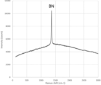
- FIG. 2 shows the results of Raman analysis of the boron nitride particles 1.
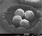
- FIG. 3 is a scanning electron microscope (SEM) photograph of the appearance of the boron nitride particles 1.
- FIG. 4(a) to (c) are scanning electron microscope (SEM) photographs of the cross section of the boron nitride particles 1.
- the cross section of the boron nitride particles of the present invention has linear voids. If the cross-sectional voids of the boron nitride particles are not streak-like, the cross-sectional voids of the boron nitride particles become large, and the thermal conductivity of the boron nitride particles becomes low. The voids in the cross section of the boron nitride particles formed by agglomeration of scale-like primary particles of boron nitride do not form streaks.
- the cross-sectional porosity (area ratio) of the boron nitride particles of the present invention is preferably 5% or less.
- the thermal conductivity of the boron nitride particles can be further increased.
- the cross-sectional porosity of the boron nitride particles is 5% or less, the resin does not enter the interior of the boron nitride particles, so the filling amount of the boron nitride particles in the heat dissipation sheet can be increased, thereby improving heat dissipation.
- the thermal conductivity of the sheet can be further increased.
- the cross-sectional porosity of the boron nitride particles is more preferably 4% or less, and still more preferably 3% or less.
- the lower limit of the range of the cross-sectional porosity of the boron nitride particles of the present invention is not particularly limited, but is usually 0.1% or more. Moreover, the lower limit may be 0.5% or more and 1.0% or more.
- the cross-sectional porosity of the boron nitride particles can be measured by the method described in Examples below.
- boron nitride particles formed by aggregating scaly primary particles of boron nitride it is difficult to densely aggregate (aggregate) the primary particles of boron nitride, so that the scaly primary particles of boron nitride are It is difficult to make the cross-sectional porosity of the aggregated boron nitride particles 5% or less.
- the ratio of length to width of the voids (length/width) is preferably 3-30.
- the ratio of the length to the width of the voids (length/width) is 3 or more, the porosity of the cross section of the boron nitride particles can be reduced, so that the thermal conductivity of the boron nitride particles can be increased. .
- the lower limit may be 5 or more and 10 or more.
- the ratio of the length to the width of the void (length/width) is 30 or less, the strength of the boron nitride particles can be increased. Destruction of particles can be suppressed. From this point of view, the ratio of the length to the width of the void (length/width) is more preferably 5-25, still more preferably 6-20, and even more preferably 10-20.
- the width of voids is preferably 0.5 ⁇ m or less.
- the width of the voids is 0.5 ⁇ m or less, the porosity of the cross section of the boron nitride particles can be reduced, so that the thermal conductivity of the boron nitride particles can be increased.
- the width of the gap is more preferably 0.4 ⁇ m or less, and still more preferably 0.3 ⁇ m or less.
- the lower limit of the range of void width is not particularly limited, but is usually 0.01 ⁇ m or more, may be 0.05 ⁇ m or more, or may be 0.1 ⁇ m or more. good.
- the width of voids in the cross section of the boron nitride particles can be measured by the method described in Examples below.
- the voids in the cross section of the boron nitride particles formed by aggregating the scaly primary particles of boron nitride are not streaky, the voids in the cross section of the boron nitride particles formed by aggregating the scaly primary particles of boron nitride are formed.
- the average width is greater than 0.5 ⁇ m.
- the cross section of the boron nitride particles of the present invention preferably has a plurality of voids, and at least one of the voids is preferably a streaky void along the circumferential direction.
- the streak-like void means a void having a ratio of length to width of 3 or more.
- half or more of the multiple voids in the cross section of the boron nitride particle of the present invention are linear voids along the circumferential direction, and the number of multiple voids in the cross section of the boron nitride particle of the present invention is more preferable. It is more preferable that two-thirds or more of the voids are linear voids along the circumferential direction, and all the voids of the plurality of voids in the cross section of the boron nitride particles of the present invention are along the circumferential direction. Streaky voids are even more preferable.
- the direction in which the linear voids extend in the cross section of the boron nitride particles can be measured by the method described in Examples below.
- the average particle size of the boron nitride particles of the present invention is not particularly limited, it is preferably 30 ⁇ m or less, more preferably 25 ⁇ m or less, and still more preferably 21 ⁇ m or less.
- the average particle size of the boron nitride particles of the present invention is preferably 1 ⁇ m or more, more preferably 2 ⁇ m or more, and still more preferably 3 ⁇ m or more.
- the average particle size of the boron nitride particles can be measured by the method described in Examples below.
- the crushing strength of the boron nitride particles of the present invention is preferably 10 MPa or more.
- the crushing strength of the boron nitride particles is 10 MPa or more, for example, it is possible to suppress the boron nitride particles from being broken while the resin and the boron nitride particles are mixed to produce a heat dissipation sheet. can.
- the crushing strength of the boron nitride particles of the present invention is more preferably 13 MPa or more, still more preferably 15 MPa or more, and even more preferably 20 MPa or more.
- the upper limit of the crushing strength range of the boron nitride particles of the present invention is not particularly limited, it is usually 40 MPa or less, may be 35 MPa or less, or may be 30 MPa or less.
- the crushing strength of boron nitride particles can be measured by the method described in Examples below.
- the average circularity of the boron nitride particles of the present invention is preferably 0.9 or more.
- the average circularity of the boron nitride particles is 0.9 or more, the flowability of the boron nitride particles is improved.
- resin and boron nitride particles are mixed to produce a heat dissipation sheet, it becomes easy to fill the resin with boron nitride particles, and the generation of voids in the heat dissipation sheet is suppressed. can do.
- the average circularity of the boron nitride particles of the present invention is more preferably 0.91 or more, still more preferably 0.92 or more, and even more preferably 0.95 or more.
- the upper limit of the average circularity range of the boron nitride particles of the present invention is not particularly limited, but is usually 0.99 or less, may be 0.97 or less, or may be 0.96 or less.
- the average circularity of boron nitride particles can be measured by the method described in Examples below.
- the boron nitride particles of the present invention can be produced, for example, by the following production method.
- An example of the method for producing boron nitride particles of the present invention will be described with reference to FIG.
- a mixture 2 containing boron carbide and boric acid is placed in a container 3 made of a carbon material whose opening is closed with a lid 4 made of a carbon material, A step of arranging the substrate 6 made of a carbon material under the lid 4 (placement step), and heating and pressurizing the inside of the container 3 in a nitrogen atmosphere, thereby removing the substrate 6 under the lid 3. and a step of generating boron nitride particles (generating step).
- the container 3 made of a carbon material is a container that can contain the mixture 2 described above.
- a substrate 5 made of a carbon material may be further arranged inside the container 3 .
- Said container 3 may be, for example, a carbon crucible.
- a lid 4 made of a carbon material closes the opening of the container 3 and increases the vapor pressure of the boron compound produced by heating the mixture 2 in the container 3 .
- the mixture 2 may be arranged at the bottom inside the container 3
- the substrate 5 may be arranged at the sidewall surface inside the container 3
- the substrate 6 may be arranged under the lid 4 .
- the substrates 5 and 6 made of a carbon material may be sheet-shaped, plate-shaped, or rod-shaped, for example.
- the substrates 5 and 6 made of carbon material may be, for example, carbon sheets (graphite sheets), carbon plates, or carbon rods.
- the boron carbide in the mixture 2 may be powdery (boron carbide powder), for example.
- the boric acid in the mixture 2 may be in powder form (boric acid powder), for example.
- Mixture 2 is obtained, for example, by mixing boron carbide powder and boric acid powder by a known method.
- Boron carbide powder can be produced by a known production method.
- a method for producing boron carbide powder for example, after mixing boric acid and acetylene black, the mixture is heated in an inert gas (eg, nitrogen gas) atmosphere at 1800 to 2400° C. for 1 to 10 hours to form lumps. Methods of obtaining boron carbide particles are mentioned.
- Boron carbide powder can be obtained by appropriately performing pulverization, sieving, washing, impurity removal, drying, and the like on the aggregated boron carbide particles obtained by this method.
- the average particle size of the boron carbide powder can be adjusted by adjusting the pulverization time of the lumpy carbon boron particles.
- the average particle size of the boron carbide powder may be 5 ⁇ m or more, 7 ⁇ m or more, or 10 ⁇ m or more, and may be 100 ⁇ m or less, 90 ⁇ m or less, 80 ⁇ m or less, or 70 ⁇ m or less.
- the average particle size of boron carbide powder can be measured by a laser diffraction scattering method.
- the mixing ratio of boron carbide and boric acid can be selected as appropriate.
- the content of boric acid in the mixture is preferably 2 parts by mass or more, more preferably 5 parts by mass or more, and still more preferably, with respect to 100 parts by mass of boron carbide, from the viewpoint that the boron nitride particles tend to be large. is 8 parts by mass or more, and may be 100 parts by mass or less, 90 parts by mass or less, or 80 parts by mass or less.
- the mixture containing boron carbide and boric acid may further contain other components.
- Other components include silicon carbide, carbon, iron oxide, and the like. Further containing silicon carbide in the mixture containing boron carbide and boric acid facilitates obtaining boron nitride particles having no open ends.
- the inside of the container 3 is a nitrogen atmosphere containing, for example, 95% by volume or more of nitrogen gas.
- the content of nitrogen gas in the nitrogen atmosphere is preferably 95% by volume or more, more preferably 99.9% by volume or more, and may be substantially 100% by volume.
- the nitrogen atmosphere may contain ammonia gas or the like in addition to the nitrogen gas.
- the heating temperature is preferably 1,300° C. or higher, more preferably 1,350° C. or higher, and still more preferably 1,400° C. or higher, from the viewpoint that the boron nitride particles tend to become large.
- the heating temperature may be 2100° C. or lower, 2000° C. or lower, or 1900° C. or lower.
- the pressure during pressurization is preferably 0.05 MPa or more, more preferably 0.3 MPa or more, and still more preferably 0.6 MPa or more, from the viewpoint that the boron nitride particles tend to become large.
- the pressure during pressurization may be 1.0 MPa or less, or 0.9 MPa or less.
- the time for heating and pressurizing is preferably 5 minutes or longer, more preferably 10 minutes or longer, from the viewpoint that the boron nitride particles tend to grow large.
- the time for heating and pressurizing may be 10 hours or less, or 5 hours or less.
- the boron nitride particles 1 described above are produced on the base material 6 placed under the lid 4 . Therefore, the boron nitride particles 1 are obtained by recovering the boron nitride particles 1 on the substrate 6 . Particles 1 generated on substrate 6 are boron nitride particles, part of the particles are recovered from the substrate, Raman analysis is performed on the recovered particles, and a peak derived from boron nitride is detected. can be confirmed by
- the reason why the boron nitride particles are formed on the substrate 6 by the above method is considered as follows.
- the mixture 2 in the container 3 is heated, the vapor pressure of the boron compound produced by heating the mixture 2 increases in the container 3 .
- droplets of the boron compound are formed on the surface of the base material 6 with the surface of the base material 6 arranged under the lid 4 serving as a nucleus.
- the vapor of the boron compound in the container 3 condenses on the surface of the droplet of the boron compound, and the droplet of the boron compound on the substrate 6 grows.
- the grown droplets are then nitrided.
- boron nitride particles on the substrate 6 placed under the lid 4 .
- the size of the droplets of the boron compound formed on the surface of the substrate 6 placed under the lid 4 can be controlled.
- a boron nitride powder having a desired average particle size with a small porosity for example, boron nitride particles having an average particle size of 5 ⁇ m or more and less than 30 ⁇ m and a small porosity can be obtained.
- the heat-dissipating sheet of the present invention is obtained by molding the thermally conductive resin composition containing the boron nitride particles of the present invention and a resin.
- resins used in the heat-dissipating sheet of the present invention include epoxy resins, silicone resins, silicone rubbers, acrylic resins, phenolic resins, melamine resins, urea resins, unsaturated polyesters, fluororesins, polyimides, polyamideimides, and polyetherimides.
- polybutylene terephthalate polyethylene terephthalate, polyphenylene ether, polyphenylene sulfide, wholly aromatic polyester, polysulfone, liquid crystal polymer, polyethersulfone, polycarbonate, maleimide modified resin, ABS (acrylonitrile-butadiene-styrene) resin, AAS (acrylonitrile-acrylic rubber ⁇ Styrene) resin, AES (acrylonitrile-ethylene-propylene-diene rubber-styrene) resin, and the like.
- ABS acrylonitrile-butadiene-styrene
- AAS acrylonitrile-acrylic rubber ⁇ Styrene
- AES acrylonitrile-ethylene-propylene-diene rubber-styrene
- the content of the boron nitride particles is 15% by volume or more and 20% by volume based on the total volume of the thermally conductive resin composition. Above, it may be 30% by volume or more, 40% by volume or more, 50% by volume or more, or 60% by volume or more.
- the content of boron nitride particles can suppress the formation of voids when the thermally conductive resin composition is formed into a sheet-shaped heat dissipating material, and can suppress deterioration in the insulating properties and mechanical strength of the sheet-shaped heat dissipating material. From the viewpoint, based on the total volume of the thermally conductive resin composition, it may be 85% by volume or less, 80% by volume or less, 70% by volume or less, 60% by volume or less, 50% by volume or less, or 40% by volume or less. .
- the content of the resin may be appropriately adjusted according to the application, required properties, and the like of the resin composition.
- the resin content is, for example, 15% by volume or more, 20% by volume or more, 30% by volume or more, 40% by volume or more, 50% by volume or more, or 60% by volume, based on the total volume of the thermally conductive resin composition. 85% by volume or less, 70% by volume or less, 60% by volume or less, 50% by volume or less, or 40% by volume or less.
- the thermally conductive resin composition may further contain a curing agent that cures the resin.
- a curing agent is appropriately selected according to the type of resin.
- curing agents used together with epoxy resins include phenol novolak compounds, acid anhydrides, amino compounds, imidazole compounds and the like, and imidazole compounds are preferably used.
- the content of the curing agent may be, for example, 0.5 parts by mass or more or 1 part by mass or more, and may be 15 parts by mass or less or 10 parts by mass or less with respect to 100 parts by mass of the resin.
- the thermally conductive resin composition may further contain other components.
- Other components may be curing accelerators (curing catalysts), coupling agents, wetting and dispersing agents, surface control agents, and the like.
- Curing accelerators include, for example, phosphorus-based curing accelerators such as tetraphenylphosphonium tetraphenylborate and triphenylphosphate; imidazole-based curing accelerators such as 2-phenyl-4,5-dihydroxymethylimidazole; Examples include amine-based curing accelerators such as boron trifluoride monoethylamine.
- coupling agents examples include silane-based coupling agents, titanate-based coupling agents, and aluminate-based coupling agents.
- Chemical bonding groups contained in these coupling agents include vinyl groups, epoxy groups, amino groups, methacryl groups, mercapto groups, and the like.
- wetting and dispersing agents include phosphate salts, carboxylic acid esters, polyesters, acrylic copolymers, block copolymers, and the like.
- surface modifiers examples include acrylic surface modifiers, silicone-based surface modifiers, vinyl-based modifiers, fluorine-based surface modifiers, and the like.
- the heat-dissipating sheet of the present invention can be prepared, for example, by blending the boron nitride particles of the present invention with a resin to prepare a thermally conductive resin composition (A), molding the thermally conductive resin composition into a sheet, It can be produced by a production method including the step (B) of producing a thermally conductive resin composition sheet and the step (C) of heating and pressurizing the thermally conductive resin composition sheet under vacuum.
- Step (A) In step (A), the boron nitride particles of the present invention and a resin are blended to produce a thermally conductive resin composition.
- the boron nitride particles and the resin used in step (A) have already been explained, so the explanation will be omitted.
- the thermally conductive resin composition is formed into a sheet to produce a thermally conductive resin composition sheet.
- the thermally conductive resin composition can be formed into a sheet by a doctor blade method or calendering.
- the thermally conductive resin composition passes through the calender rolls, the boron nitride particles in the thermally conductive resin composition may be destroyed. Therefore, it is preferable to mold the thermally conductive resin composition into a sheet by the doctor blade method.
- step (C) the thermally conductive resin composition sheet is heated and pressed under vacuum.
- the pressure of the vacuum environment when heating and pressurizing the thermally conductive resin composition sheet is preferably 0.1 to 5 kPa, more preferably 0.1 to 3 kPa.
- the heating temperature of the thermally conductive resin composition sheet is preferably 120 to 200.degree. C., more preferably 130 to 180.degree.
- the pressure when pressing the thermally conductive resin composition sheet is preferably 80 to 250 kg/cm 2 , more preferably 100 to 200 kg/cm 2 .
- the cross section of the boron nitride particles was observed using a scanning electron microscope (eg, "JSM-6010LA” (manufactured by JEOL Ltd.)) to examine the shape of the voids and the direction in which the linear voids extend.
- a scanning electron microscope eg, "JSM-6010LA” (manufactured by JEOL Ltd.)
- a cured resin was produced in the same manner as in the evaluation of the shape of voids and the direction in which streak-like voids extend, and osmium coating was applied to the cut surface cut with a diamond cutter. Then, the cross section of the boron nitride particles was photographed using a scanning electron microscope (for example, "JSM-6010LA” (manufactured by JEOL Ltd.) at a magnification of 3000 times for 10 fields of view. Using image analysis software (trade name: Mac-View, manufactured by Mountec Co., Ltd.), the captured image is binarized so that voids can be extracted from the captured image of the cross section of the boron nitride particles, and 10 fields of view. The area ratio of the porosity in the cross section of the boron nitride particles was measured for the image of , and the average value was taken as the porosity in the cross section of the boron nitride particles.
- a cured resin was produced in the same manner as in the evaluation of the shape of the voids and the direction in which the streaky voids extend, and the cut surface cut with a diamond cutter was polished. After fixing the cured resin with the cut surface polished to the sample table, the cut surface of the cured resin was coated with osmium. Then, the cross section of the boron nitride particles was photographed using a scanning electron microscope (for example, "JSM-6010LA" (manufactured by JEOL Ltd.) at a magnification of 3000 times for 10 fields of view.
- a scanning electron microscope for example, "JSM-6010LA" (manufactured by JEOL Ltd.) at a magnification of 3000 times for 10 fields of view.
- the photographed image of the cross section of the boron nitride particles was binarized so that the voids could be extracted. Then, for 100 pores, the maximum pore length and pore width are measured, and the average pore length and the average pore width are calculated as the pore width in the cross section of the boron nitride particles. and length. Then, the ratio of the length to the width of the void (length/width) was calculated.
- Average particle size SEM observation ( ⁇ 500) was performed on 50 particles collected from the substrate, and the average particle diameter was calculated from the 50 images.
- boron nitride particles 1 The aggregated boron carbide particles were pulverized by a pulverizer to obtain boron carbide powder having an average particle size of 10 ⁇ m. 100 parts by mass of the obtained boron carbide powder and 72 parts by mass of boric acid are mixed, filled in a carbon crucible, the opening of the carbon crucible is covered with a carbon sheet (manufactured by NeoGraf), and the lid of the carbon crucible and the carbon crucible The carbon sheet was fixed by sandwiching the carbon sheet with. Particles were generated on the carbon sheet by heating the capped carbon crucible in a resistance heating furnace under conditions of 1600° C. and 0.85 MPa for 10 minutes in a nitrogen gas atmosphere.
- the carbon sheet with particles was washed with hot water at 80°C. Then, the hot water used for washing was suction-filtered to recover the particles generated on the carbon sheet.
- Raman analysis was performed on the collected particles using a Raman spectrometer (manufactured by Horiba, Ltd., trade name "XploRA PLUS"). The results of this Raman analysis are shown in FIG. As can be seen from FIG. 2, only the peak derived from boron nitride was detected, confirming that boron nitride particles were produced.
- Boron nitride particles 2 were produced in the same manner as for boron nitride particles 1, except that the amount of boric acid was changed from 72 parts by mass to 36 parts by mass. Also, it was confirmed by Raman analysis that boron nitride particles were generated.
- Boron nitride particles 3 were produced in the same manner as for boron nitride particles 1, except that the amount of boric acid was changed from 72 parts by mass to 9 parts by mass. Also, it was confirmed by Raman analysis that boron nitride particles were generated.
- Boron nitride particles 4 were produced in the same manner as for boron nitride particles 1, except that the amount of boric acid was changed from 72 parts by mass to 100 parts by mass. Also, it was confirmed by Raman analysis that boron nitride particles were generated.
- Boric acid orthoboric acid
- HS100 acetylene black
- the synthesized boron carbide mass is pulverized in a ball mill for 3 hours, sieved to a particle size of 75 ⁇ m or less using a sieve, washed with an aqueous nitric acid solution to remove impurities such as iron, filtered and dried to reduce the average particle size to 10 ⁇ m.
- a boron carbide powder was produced.
- ⁇ Decarburization crystallization step> After mixing 100 parts by mass of the synthesized boron carbonitride and 100 parts by mass of boric acid using a Henschel mixer, the mixture was filled in a boron nitride crucible, and a resistance heating furnace was used at a pressure of 0.1 MPa under a nitrogen gas atmosphere. Then, the temperature was raised at a rate of 10°C/min from room temperature to 1200°C, and at a rate of 5°C/min from 1200°C, and the firing temperature was 2000°C for a holding time of 5 hours. Agglomerated boron nitride particles were synthesized in which the particles were agglomerated into agglomerates.
- boron nitride particles 5 were pulverized by 15 minutes using a Henschel mixer, they were classified with a nylon sieve having a sieve mesh of 150 ⁇ m using a sieve mesh. Boron nitride particles 5 were obtained by pulverizing and classifying the fired product. As a result of SEM observation, the obtained boron nitride particles 5 were agglomerated particles composed of agglomerated primary particles.
- Table 1 shows the evaluation results.
- SEM scanning electron microscope
- the shape of the cross-sectional voids was streaky, so the cross-sectional void ratio could be reduced.
- the shape of the cross-sectional voids was not streaky, so the cross-sectional void ratio was increased.
Abstract
本発明の窒化ホウ素粒子の断面は筋状の空隙を有する。本発明の放熱シートは、本発明の窒化ホウ素粒子と樹脂とを含む熱伝導性樹脂組成物を成形してなるものである。本発明によれば、空隙率が小さい窒化ホウ素粒子及びその窒化ホウ素粒子を含む放熱シートを提供することができる。
Description
本発明は窒化ホウ素粒子及びその窒化ホウ素粒子を含む放熱シートに関する。
六方晶窒化ホウ素(以下、「窒化ホウ素」という)は、潤滑性、高熱伝導性、及び絶縁性等を有しており、固体潤滑剤、溶融ガスやアルミニウムなどの離形剤、及び放熱材料用充填材等に幅広く利用されている。
特に近年、コンピューターや電子機器の高性能化により、放熱対策の重要性が増しており、窒化ホウ素の高熱伝導性が注目されている。また、さらに高い熱伝導性や絶縁性を放熱シートに付与させる目的で窒化ホウ素を添加することが検討されている。
窒化ホウ素は鱗片形状を有し、その熱特性は、長径もしくは短径方向の方が厚み方向に比べて圧倒的に優れている。そして、放熱シートの熱伝導性フィラーとして窒化ホウ素を使用すると、多くの場合、窒化ホウ素は横方向に寝てしまい、縦方向に必要な充分な熱特性を示さない。したがって、窒化ホウ素が熱伝導性フィラーとして好適であるためには、窒化ホウ素を球形状、もしくは凝集形状にすることで、窒化ホウ素の鱗片形状による方向性の影響を小さくする必要がある。
窒化ホウ素は、一般的に、ホウ素源(ホウ酸、硼砂等)と窒素源(尿素、メラミン、及びアンモニアなど)を高温で反応させることで得られ、ホウ酸とメラミンから鱗片状の一次粒子が凝集した「松ぼっくり」状の窒化ホウ素が提案されている(特許文献1)。これにより、窒化ホウ素の鱗片形状による方向性の影響を小さくすることができる。この方法で作製された窒化ホウ素の凝集粒子の平均粒子径は、通常50μm以上である。
また、ホウ酸アルコキシドとアンモニアを不活性ガス気流中で反応させ、アンモニアガス、又は、アンモニアガスと不活性ガスの混合ガスの雰囲気下で熱処理した後、さらに、不活性ガス雰囲気下で焼成することにより、球状窒化ホウ素微粒子を製造することが提案されている(特許文献2)。これにより、窒化ホウ素の方向性がなくなる。この方法で作製された窒化ホウ素の平均粒子径は0.01~1.0μmである。
また、ホウ酸アルコキシドとアンモニアを不活性ガス気流中で反応させ、アンモニアガス、又は、アンモニアガスと不活性ガスの混合ガスの雰囲気下で熱処理した後、さらに、不活性ガス雰囲気下で焼成することにより、球状窒化ホウ素微粒子を製造することが提案されている(特許文献2)。これにより、窒化ホウ素の方向性がなくなる。この方法で作製された窒化ホウ素の平均粒子径は0.01~1.0μmである。
また、平均粒子径の異なる凝集形状の窒化ホウ素粉末を組み合わせることも検討されている。例えば、窒化ホウ素の一次粒子が凝集してなり、平均粒子径が5μm以上30μm未満である窒化ホウ素粉末と、窒化ホウ素の一次粒子が凝集してなり、平均粒子径が50μm以上100μm未満である窒化ホウ素粉末とを混合して得られた混合窒化ホウ素粉末を熱伝導性フィラーとして用いることが提案されている(特許文献3)。これにより、放熱シートの耐電圧性を改善することができる。
特許文献3に記載の窒化ホウ素粉末では、平均粒子径が50μm以上100μm未満である窒化ホウ素粒子も、平均粒子径が5μm以上30μm未満である窒化ホウ素粒子も、窒化ホウ素の一次粒子が凝集してなる窒化ホウ素粒子である。ところで、窒化ホウ素の一次粒子が凝集してなる窒化ホウ素粒子は、平均粒子径が小さい場合、窒化ホウ素の一次粒子の鱗片状の形状の影響で、窒化ホウ素粒子の空隙率が大きくなってしまう。このため、窒化ホウ素粒子の平均粒子径が30μm未満である場合、窒化ホウ素粒子の空隙率を十分低減できない場合がある。窒化ホウ素粒子の空隙率が大きいと、窒化ホウ素粒子の熱伝導率が低くなる。
また、特許文献2に記載の球状窒化ホウ素微粒子の製造方法では、空隙率の低い窒化ホウ素粒子を製造できるが、平均粒子径が5μm以上30μm未満である窒化ホウ素粒子を製造することが難しい。
また、特許文献2に記載の球状窒化ホウ素微粒子の製造方法では、空隙率の低い窒化ホウ素粒子を製造できるが、平均粒子径が5μm以上30μm未満である窒化ホウ素粒子を製造することが難しい。
そこで、本発明は、今まで製造することが困難であった、空隙率が低い窒化ホウ素粒子、例えば、平均粒子径が5μm以上30μm未満であっても、空隙率が小さい窒化ホウ素粒子にできる特徴を有する窒化ホウ素粒子を提供すること、及びその窒化ホウ素粒子を含む放熱シートを提供することを目的とする。
本発明者らは、鋭意研究を進めたところ、窒化ホウ素粒子の断面の空隙が所定の形状となるようにすることによって、上記課題を解決できることを見出し、本発明を完成させた。本発明は、以下を要旨とする。
[1]断面が筋状の空隙を有する窒化ホウ素粒子。
[2]空隙率が5%以下である上記[1]に記載の窒化ホウ素粒子。
[3]前記空隙の幅に対する長さの比(長さ/幅)が3~30であり、前記幅が0.5μm以下である上記[1]又は[2]に記載の窒化ホウ素粒子。
[4]前記空隙を複数有し、少なくとも1つの空隙が円周方向に沿った筋状の空隙である上記[1]~[3]のいずれか1つに記載の窒化ホウ素粒子。
[5]圧壊強度が10~40MPaである上記[1]~[4]のいずれか1つに記載の窒化ホウ素粒子。
[6]平均円形度が0.9以上である上記[1]~[5]のいずれか1つに記載の窒化ホウ素粒子。
[7]上記[1]~[6]のいずれか1つに記載の窒化ホウ素粒子と樹脂とを含む熱伝導性樹脂組成物を成形してなる放熱シート。
本発明によれば、空隙率が小さい窒化ホウ素粒子及びその窒化ホウ素粒子を含む放熱シートを提供することができる。
以下、本発明の実施形態について説明する。なお、本発明は以下の実施形態に限定されない。
[窒化ホウ素粒子]
(空隙の形状)
本発明の窒化ホウ素粒子の断面は筋状の空隙を有する。窒化ホウ素粒子の断面の空隙が筋状でないと、窒化ホウ素粒子の断面の空隙が大きくなり、窒化ホウ素粒子の熱伝導率が小さくなる。なお、鱗片状の窒化ホウ素の一次粒子が凝集してなる窒化ホウ素粒子の断面の空隙は筋状とはならない。
(空隙の形状)
本発明の窒化ホウ素粒子の断面は筋状の空隙を有する。窒化ホウ素粒子の断面の空隙が筋状でないと、窒化ホウ素粒子の断面の空隙が大きくなり、窒化ホウ素粒子の熱伝導率が小さくなる。なお、鱗片状の窒化ホウ素の一次粒子が凝集してなる窒化ホウ素粒子の断面の空隙は筋状とはならない。
(空隙率)
本発明の窒化ホウ素粒子の断面の空隙率(面積率)は、好ましくは5%以下である。窒化ホウ素粒子の断面の空隙率が5%以下であると、窒化ホウ素粒子の熱伝導率をさらに高くすることができる。また、窒化ホウ素粒子の断面の空隙率が5%以下であると、窒化ホウ素粒子の内部に樹脂が入り込まないので、放熱シートにおける窒化ホウ素粒子の充填量を高くすることができ、それにより、放熱シートの熱伝導率をさらに高くすることができる。このような観点から、窒化ホウ素粒子の断面の空隙率は、より好ましくは4%以下であり、さらに好ましくは3%以下である。また、本発明の窒化ホウ素粒子の断面の空隙率の範囲の下限値は特に限定されないが、通常0.1%以上である。また、下限は0.5%以上、1.0%以上であってよい。なお、窒化ホウ素粒子の断面の空隙率は、後述の実施例に記載の方法で測定することができる。また、鱗片状の窒化ホウ素の一次粒子が凝集してなる窒化ホウ素粒子において、窒化ホウ素の一次粒子を密に凝集(集合)させることは困難であることから、鱗片状の窒化ホウ素の一次粒子が凝集してなる窒化ホウ素粒子の断面の空隙率を5%以下とすることは難しい。
本発明の窒化ホウ素粒子の断面の空隙率(面積率)は、好ましくは5%以下である。窒化ホウ素粒子の断面の空隙率が5%以下であると、窒化ホウ素粒子の熱伝導率をさらに高くすることができる。また、窒化ホウ素粒子の断面の空隙率が5%以下であると、窒化ホウ素粒子の内部に樹脂が入り込まないので、放熱シートにおける窒化ホウ素粒子の充填量を高くすることができ、それにより、放熱シートの熱伝導率をさらに高くすることができる。このような観点から、窒化ホウ素粒子の断面の空隙率は、より好ましくは4%以下であり、さらに好ましくは3%以下である。また、本発明の窒化ホウ素粒子の断面の空隙率の範囲の下限値は特に限定されないが、通常0.1%以上である。また、下限は0.5%以上、1.0%以上であってよい。なお、窒化ホウ素粒子の断面の空隙率は、後述の実施例に記載の方法で測定することができる。また、鱗片状の窒化ホウ素の一次粒子が凝集してなる窒化ホウ素粒子において、窒化ホウ素の一次粒子を密に凝集(集合)させることは困難であることから、鱗片状の窒化ホウ素の一次粒子が凝集してなる窒化ホウ素粒子の断面の空隙率を5%以下とすることは難しい。
(空隙の幅に対する長さの比(長さ/幅))
本発明の窒化ホウ素粒子の断面において、空隙の幅に対する長さの比(長さ/幅)は、好ましくは3~30である。空隙の幅に対する長さの比(長さ/幅)が3以上であると、窒化ホウ素粒子の断面の空隙率を低くすることができるので、窒化ホウ素粒子の熱伝導率を高くすることができる。下限は5以上、10以上であってよい。また、空隙の幅に対する長さの比(長さ/幅)が30以下であると、窒化ホウ素粒子の強度を高くすることができるので、樹脂と窒化ホウ素粒子とを混合しているとき窒化ホウ素粒子が破壊されることを抑制できる。このような観点から、空隙の幅に対する長さの比(長さ/幅)は、より好ましくは5~25であり、さらに好ましくは6~20であり、よりさらに好ましくは10~20である。
本発明の窒化ホウ素粒子の断面において、空隙の幅に対する長さの比(長さ/幅)は、好ましくは3~30である。空隙の幅に対する長さの比(長さ/幅)が3以上であると、窒化ホウ素粒子の断面の空隙率を低くすることができるので、窒化ホウ素粒子の熱伝導率を高くすることができる。下限は5以上、10以上であってよい。また、空隙の幅に対する長さの比(長さ/幅)が30以下であると、窒化ホウ素粒子の強度を高くすることができるので、樹脂と窒化ホウ素粒子とを混合しているとき窒化ホウ素粒子が破壊されることを抑制できる。このような観点から、空隙の幅に対する長さの比(長さ/幅)は、より好ましくは5~25であり、さらに好ましくは6~20であり、よりさらに好ましくは10~20である。
(空隙の幅)
本発明の窒化ホウ素粒子の断面において、空隙の幅は、好ましくは0.5μm以下である。空隙の幅が0.5μm以下であると、窒化ホウ素粒子の断面の空隙率を低くすることができるので、窒化ホウ素粒子の熱伝導率を高くすることができる。このような観点から、空隙の幅は、より好ましくは0.4μm以下であり、さらに好ましくは0.3μm以下である。本発明の窒化ホウ素粒子の断面において、空隙の幅の範囲の下限値は特に限定されないが、通常、0.01μm以上であり、0.05μm以上であってよく、0.1μm以上であってもよい。なお、窒化ホウ素粒子の断面における空隙の幅は、後述の実施例に記載の方法で測定することができる。また、鱗片状の窒化ホウ素の一次粒子が凝集してなる窒化ホウ素粒子の断面の空隙は筋状ではないので、鱗片状の窒化ホウ素の一次粒子が凝集してなる窒化ホウ素粒子の断面において空隙の幅の平均値は0.5μmよりも大きくなる。
本発明の窒化ホウ素粒子の断面において、空隙の幅は、好ましくは0.5μm以下である。空隙の幅が0.5μm以下であると、窒化ホウ素粒子の断面の空隙率を低くすることができるので、窒化ホウ素粒子の熱伝導率を高くすることができる。このような観点から、空隙の幅は、より好ましくは0.4μm以下であり、さらに好ましくは0.3μm以下である。本発明の窒化ホウ素粒子の断面において、空隙の幅の範囲の下限値は特に限定されないが、通常、0.01μm以上であり、0.05μm以上であってよく、0.1μm以上であってもよい。なお、窒化ホウ素粒子の断面における空隙の幅は、後述の実施例に記載の方法で測定することができる。また、鱗片状の窒化ホウ素の一次粒子が凝集してなる窒化ホウ素粒子の断面の空隙は筋状ではないので、鱗片状の窒化ホウ素の一次粒子が凝集してなる窒化ホウ素粒子の断面において空隙の幅の平均値は0.5μmよりも大きくなる。
(筋状の空隙の延びる方向)
本発明の窒化ホウ素粒子の断面は、好ましくは空隙を複数有し、それらの空隙の中で少なくとも1つの空隙が円周方向に沿った筋状の空隙であることが好ましい。筋状の空隙が延びる方向が円周方向であると、空隙による窒化ホウ素粒子の強度低下を抑制することができる。なお、筋状の空隙とは、空隙の幅に対する長さの比が3以上の空隙をいう。本発明の窒化ホウ素粒子の断面における複数の空隙の半分以上の数の空隙が円周方向に沿った筋状の空隙であることがより好ましく、本発明の窒化ホウ素粒子の断面における複数の空隙の3分の2以上の数の空隙が円周方向に沿った筋状の空隙であることがさらに好ましく、本発明の窒化ホウ素粒子の断面における複数の空隙の全ての空隙が円周方向に沿った筋状の空隙であることがよりさらに好ましい。なお、窒化ホウ素粒子の断面における筋状の空隙の延びる方向は、後述の実施例に記載の方法で測定することができる。
本発明の窒化ホウ素粒子の断面は、好ましくは空隙を複数有し、それらの空隙の中で少なくとも1つの空隙が円周方向に沿った筋状の空隙であることが好ましい。筋状の空隙が延びる方向が円周方向であると、空隙による窒化ホウ素粒子の強度低下を抑制することができる。なお、筋状の空隙とは、空隙の幅に対する長さの比が3以上の空隙をいう。本発明の窒化ホウ素粒子の断面における複数の空隙の半分以上の数の空隙が円周方向に沿った筋状の空隙であることがより好ましく、本発明の窒化ホウ素粒子の断面における複数の空隙の3分の2以上の数の空隙が円周方向に沿った筋状の空隙であることがさらに好ましく、本発明の窒化ホウ素粒子の断面における複数の空隙の全ての空隙が円周方向に沿った筋状の空隙であることがよりさらに好ましい。なお、窒化ホウ素粒子の断面における筋状の空隙の延びる方向は、後述の実施例に記載の方法で測定することができる。
(平均粒子径)
本発明の窒化ホウ素粒子の平均粒子径は特に限定されないが、好ましくは30μm以下であり、より好ましくは25μm以下であり、さらに好ましくは21μm以下である。また、一方、本発明の窒化ホウ素粒子の平均粒子径は、好ましくは1μm以上であり、より好ましくは2μm以上であり、さらに好ましくは3μm以上である。なお、窒化ホウ素粒子の平均粒子径は、後述の実施例に記載の方法で測定することができる。
本発明の窒化ホウ素粒子の平均粒子径は特に限定されないが、好ましくは30μm以下であり、より好ましくは25μm以下であり、さらに好ましくは21μm以下である。また、一方、本発明の窒化ホウ素粒子の平均粒子径は、好ましくは1μm以上であり、より好ましくは2μm以上であり、さらに好ましくは3μm以上である。なお、窒化ホウ素粒子の平均粒子径は、後述の実施例に記載の方法で測定することができる。
(圧壊強度)
本発明の窒化ホウ素粒子の圧壊強度は、好ましくは10MPa以上である。窒化ホウ素粒子の圧壊強度が10MPa以上であると、例えば、放熱シートを作製するために、樹脂と窒化ホウ素粒子とを混合している間に、窒化ホウ素粒子が破壊されることを抑制することができる。このような観点から、本発明の窒化ホウ素粒子の圧壊強度は、より好ましくは13MPa以上であり、さらに好ましくは15MPa以上であり、よりさらに好ましくは20MPa以上である。本発明の窒化ホウ素粒子の圧壊強度の範囲の上限値は特に限定されないが、通常、40MPa以下であり、35MPa以下であってもよく、30MPa以下であってよい。なお、窒化ホウ素粒子の圧壊強度は、後述の実施例に記載の方法で測定することができる。
本発明の窒化ホウ素粒子の圧壊強度は、好ましくは10MPa以上である。窒化ホウ素粒子の圧壊強度が10MPa以上であると、例えば、放熱シートを作製するために、樹脂と窒化ホウ素粒子とを混合している間に、窒化ホウ素粒子が破壊されることを抑制することができる。このような観点から、本発明の窒化ホウ素粒子の圧壊強度は、より好ましくは13MPa以上であり、さらに好ましくは15MPa以上であり、よりさらに好ましくは20MPa以上である。本発明の窒化ホウ素粒子の圧壊強度の範囲の上限値は特に限定されないが、通常、40MPa以下であり、35MPa以下であってもよく、30MPa以下であってよい。なお、窒化ホウ素粒子の圧壊強度は、後述の実施例に記載の方法で測定することができる。
(平均円形度)
本発明の窒化ホウ素粒子の平均円形度は、好ましくは0.9以上である。窒化ホウ素粒子の平均円形度が0.9以上であると、窒化ホウ素粒子の流動性が良好となる。その結果、例えば、放熱シートを作製するために、樹脂と窒化ホウ素粒子とを混合したとき、樹脂中に窒化ホウ素粒子を充填させることが容易になり、放熱シート内にボイドが発生することを抑制することができる。このような観点から、本発明の窒化ホウ素粒子の平均円形度は、より好ましくは0.91以上であり、さらに好ましくは0.92以上であり、よりさらに好ましくは0.95以上である。本発明の窒化ホウ素粒子の平均円形度の範囲の上限値は特に限定されないが、通常、0.99以下であり、0.97以下であってよく、0.96以下であってもよい。なお、窒化ホウ素粒子の平均円形度は、後述の実施例に記載の方法で測定することができる。
本発明の窒化ホウ素粒子の平均円形度は、好ましくは0.9以上である。窒化ホウ素粒子の平均円形度が0.9以上であると、窒化ホウ素粒子の流動性が良好となる。その結果、例えば、放熱シートを作製するために、樹脂と窒化ホウ素粒子とを混合したとき、樹脂中に窒化ホウ素粒子を充填させることが容易になり、放熱シート内にボイドが発生することを抑制することができる。このような観点から、本発明の窒化ホウ素粒子の平均円形度は、より好ましくは0.91以上であり、さらに好ましくは0.92以上であり、よりさらに好ましくは0.95以上である。本発明の窒化ホウ素粒子の平均円形度の範囲の上限値は特に限定されないが、通常、0.99以下であり、0.97以下であってよく、0.96以下であってもよい。なお、窒化ホウ素粒子の平均円形度は、後述の実施例に記載の方法で測定することができる。
(窒化ホウ素粒子の製造方法)
本発明の窒化ホウ素粒子は、例えば、以下の製造方法により製造することができる。本発明の窒化ホウ素粒子の製造方法の一例を、図1を参照して説明する。窒化ホウ素粒子は、例えば、炭素材料で形成された蓋4で開口部が塞がれた、炭素材料で形成された容器3の中に、炭化ホウ素及びホウ酸を含有する混合物2を配置し、炭素材料で形成された基材6を蓋4の下に配置する工程(配置工程)と、容器3内を窒素雰囲気にした状態で加熱及び加圧することにより、蓋3の下の基材6上に窒化ホウ素粒子を生成させる工程(生成工程)と、を備える窒化ホウ素粒子の製造方法により製造することができる。
本発明の窒化ホウ素粒子は、例えば、以下の製造方法により製造することができる。本発明の窒化ホウ素粒子の製造方法の一例を、図1を参照して説明する。窒化ホウ素粒子は、例えば、炭素材料で形成された蓋4で開口部が塞がれた、炭素材料で形成された容器3の中に、炭化ホウ素及びホウ酸を含有する混合物2を配置し、炭素材料で形成された基材6を蓋4の下に配置する工程(配置工程)と、容器3内を窒素雰囲気にした状態で加熱及び加圧することにより、蓋3の下の基材6上に窒化ホウ素粒子を生成させる工程(生成工程)と、を備える窒化ホウ素粒子の製造方法により製造することができる。
炭素材料で形成された容器3は、上記混合物2を収容できるような容器である。なお、容器3の内側には、炭素材料で形成された基材5をさらに配置してもよい。当該容器3は、例えばカーボンルツボであってよい。炭素材料で形成された蓋4は、容器3の開口部を塞ぎ、容器3内において混合物2を加熱することにより生成したホウ素化合物の蒸気圧を高くする。配置工程では、例えば、容器3内の底部に混合物2を配置し、基材5を容器3内の側壁面に配置し、基材6を蓋4の下に配置してよい。炭素材料で形成された基材5,6は、例えばシート状、板状、棒状であってよい。炭素材料で形成された基材5,6は、例えば、カーボンシート(グラファイトシート)、カーボン板、カーボン棒であってよい。
混合物2中の炭化ホウ素は、例えば粉末状(炭化ホウ素粉末)であってよい。混合物2中のホウ酸は、例えば粉末状(ホウ酸粉末)であってよい。混合物2は、例えば、炭化ホウ素粉末とホウ酸粉末とを公知の方法で混合することにより得られる。
炭化ホウ素粉末は、公知の製造方法により製造することができる。炭化ホウ素粉末の製造方法としては、例えば、ホウ酸とアセチレンブラックとを混合した後、不活性ガス(例えば窒素ガス)雰囲気中で、1800~2400℃にて、1~10時間加熱し、塊状の炭化ホウ素粒子を得る方法が挙げられる。この方法により得られた塊状の炭化ホウ素粒子を、粉砕、篩分け、洗浄、不純物除去、乾燥等を適宜行うことで炭化ホウ素粉末を得ることができる。
塊状の炭素ホウ素粒子の粉砕時間を調整することによって、炭化ホウ素粉末の平均粒子径を調整することができる。炭化ホウ素粉末の平均粒子径は、5μm以上、7μm以上、又は10μm以上であってよく、100μm以下、90μm以下、80μm以下、又は70μm以下であってよい。炭化ホウ素粉末の平均粒子径は、レーザー回折散乱法により測定することができる。
炭化ホウ素とホウ酸との混合比率は、適宜選択できる。混合物中のホウ酸の含有量は、窒化ホウ素粒子が大きくなりやすい観点から、炭化ホウ素100質量部に対して、好ましくは2質量部以上であり、より好ましくは5質量部以上であり、さらに好ましくは8質量部以上であり、100質量部以下、90質量部以下、又は80質量部以下であってよい。
炭化ホウ素及びホウ酸を含有する混合物は、他の成分をさらに含有してもよい。他の成分としては、炭化ケイ素、炭素、酸化鉄等が挙げられる。炭化ホウ素及びホウ酸を含有する混合物が炭化ケイ素をさらに含むことで、開口端を有さない窒化ホウ素粒子を得やすくなる。
容器3内は、例えば95体積%以上の窒素ガスを含む窒素雰囲気となっている。窒素雰囲気中の窒素ガスの含有量は、好ましくは95体積%以上であり、より好ましくは99.9体積%以上であり、実質的に100体積%であってよい。窒素雰囲気中に、窒素ガスに加えて、アンモニアガス等が含まれてもよい。
加熱温度は、窒化ホウ素粒子が大きくなりやすい観点から、好ましくは1300℃以上であり、より好ましくは1350℃以上であり、さらに好ましくは1400℃以上である。加熱温度は、2100℃以下、2000℃以下、又は1900℃以下であってよい。
加圧する際の圧力は、窒化ホウ素粒子が大きくなりやすい観点から、好ましくは0.05MPa以上であり、より好ましくは0.3MPa以上であり、さらに好ましくは0.6MPa以上である。加圧する際の圧力は、1.0MPa以下、又は0.9MPa以下であってよい。
加熱及び加圧を行う時間は、窒化ホウ素粒子が大きくなりやすい観点から、好ましくは5分間以上であり、より好ましくは10分間以上である。加熱及び加圧を行う時間は、10時間以下、又は5時間以下であってよい。
この製造方法によれば、上述した窒化ホウ素粒子1が、蓋4の下に配置された基材6上に生成する。したがって、基材6上の窒化ホウ素粒子1を回収することにより、窒化ホウ素粒子1が得られる。基材6上に生成した粒子1が窒化ホウ素粒子であることは、当該粒子の一部を基材から回収し、回収した粒子についてラマン分析を行い、窒化ホウ素に由来するピークが検出されることにより確認できる。
なお、以下の説明は本発明を限定しないが、以上の方法で基材6上に窒化ホウ素粒子が形成されるのは、以下の理由によると考えられる。容器3内の混合物2を加熱すると、容器3内において、混合物2を加熱することにより生成したホウ素化合物の蒸気圧が高くなる。その結果、蓋4の下に配置された基材6の表面が核となって、基材6の表面にホウ素化合物の液滴が形成される。その後、容器3内のホウ素化合物の蒸気がホウ素化合物の液滴の表面に凝縮して、基材6上のホウ素化合物の液滴は成長する。そして、成長した液滴が窒化される。このように液滴の成長及び窒化を繰り返すことにより、蓋4の下に配置された基材6上に窒化ホウ素粒子が形成されると考えられる。なお、ホウ酸量を調整することにより、蓋4の下に配置された基材6の表面に形成されるホウ素化合物の液滴の大きさを制御することができる。そして、これにより、空隙率が小さい所望の平均粒子径を有する窒化ホウ素粉末、例えば、平均粒子径が5μm以上30μm未満であり、空隙率が小さい窒化ホウ素粒子を得ることができる。
[放熱シート]
本発明の放熱シートは、本発明の窒化ホウ素粒子と樹脂とを含む熱伝導性樹脂組成物を成形してなるものである。
本発明の放熱シートは、本発明の窒化ホウ素粒子と樹脂とを含む熱伝導性樹脂組成物を成形してなるものである。
本発明の放熱シートに用いられる樹脂としては、例えば、エポキシ樹脂、シリコーン樹脂、シリコーンゴム、アクリル樹脂、フェノール樹脂、メラミン樹脂、ユリア樹脂、不飽和ポリエステル、フッ素樹脂、ポリイミド、ポリアミドイミド、ポリエーテルイミド、ポリブチレンテレフタレート、ポリエチレンテレフタレート、ポリフェニレンエーテル、ポリフェニレンスルフィド、全芳香族ポリエステル、ポリスルホン、液晶ポリマー、ポリエーテルスルホン、ポリカーボネート、マレイミド変性樹脂、ABS(アクリロニトリル-ブタジエン-スチレン)樹脂、AAS(アクリロニトリル-アクリルゴム・スチレン)樹脂、AES(アクリロニトリル・エチレン・プロピレン・ジエンゴム-スチレン)樹脂等が挙げられる。
(窒化ホウ素粒子の含有量)
窒化ホウ素粒子の含有量は、放熱材の熱伝導率を向上させ、優れた放熱性能が得られやすい観点から、熱伝導性樹脂組成物の全体積を基準として、15体積%以上、20体積%以上、30体積%以上、40体積%以上、50体積%以上、又は60体積%以上であってよい。窒化ホウ素粒子の含有量は、熱伝導性樹脂組成物をシート状の放熱材に成形する際に空隙が発生することを抑制し、シート状の放熱材の絶縁性及び機械強度の低下を抑制できる観点から、熱伝導性樹脂組成物の全体積を基準として、85体積%以下、80体積%以下、70体積%以下、60体積%以下、50体積%以下、又は40体積%以下であってよい。
窒化ホウ素粒子の含有量は、放熱材の熱伝導率を向上させ、優れた放熱性能が得られやすい観点から、熱伝導性樹脂組成物の全体積を基準として、15体積%以上、20体積%以上、30体積%以上、40体積%以上、50体積%以上、又は60体積%以上であってよい。窒化ホウ素粒子の含有量は、熱伝導性樹脂組成物をシート状の放熱材に成形する際に空隙が発生することを抑制し、シート状の放熱材の絶縁性及び機械強度の低下を抑制できる観点から、熱伝導性樹脂組成物の全体積を基準として、85体積%以下、80体積%以下、70体積%以下、60体積%以下、50体積%以下、又は40体積%以下であってよい。
(樹脂の含有量)
樹脂の含有量は、樹脂組成物の用途、要求特性などに応じて適宜調整してよい。樹脂の含有量は、熱伝導性樹脂組成物の全体積を基準として、例えば、15体積%以上、20体積%以上、30体積%以上、40体積%以上、50体積%以上、又は60体積%以上であってよく、85体積%以下、70体積%以下、60体積%以下、50体積%以下、又は40体積%以下であってよい。
樹脂の含有量は、樹脂組成物の用途、要求特性などに応じて適宜調整してよい。樹脂の含有量は、熱伝導性樹脂組成物の全体積を基準として、例えば、15体積%以上、20体積%以上、30体積%以上、40体積%以上、50体積%以上、又は60体積%以上であってよく、85体積%以下、70体積%以下、60体積%以下、50体積%以下、又は40体積%以下であってよい。
(硬化剤)
熱伝導性樹脂組成物は、樹脂を硬化させる硬化剤をさらに含有していてよい。硬化剤は、樹脂の種類に応じて適宜選択される。例えばエポキシ樹脂と共に用いられる硬化剤としては、フェノールノボラック化合物、酸無水物、アミノ化合物、イミダゾール化合物等が挙げられ、イミダゾール化合物が好適に用いられる。硬化剤の含有量は、樹脂100質量部に対して、例えば、0.5質量部以上又は1質量部以上であってよく、15質量部以下又は10質量部以下であってよい。
熱伝導性樹脂組成物は、樹脂を硬化させる硬化剤をさらに含有していてよい。硬化剤は、樹脂の種類に応じて適宜選択される。例えばエポキシ樹脂と共に用いられる硬化剤としては、フェノールノボラック化合物、酸無水物、アミノ化合物、イミダゾール化合物等が挙げられ、イミダゾール化合物が好適に用いられる。硬化剤の含有量は、樹脂100質量部に対して、例えば、0.5質量部以上又は1質量部以上であってよく、15質量部以下又は10質量部以下であってよい。
(その他の成分)
熱伝導性樹脂組成物は、その他の成分をさらに含有してもよい。その他の成分は、硬化促進剤(硬化触媒)、カップリング剤、湿潤分散剤、表面調整剤等であってよい。
熱伝導性樹脂組成物は、その他の成分をさらに含有してもよい。その他の成分は、硬化促進剤(硬化触媒)、カップリング剤、湿潤分散剤、表面調整剤等であってよい。
硬化促進剤(硬化触媒)としては、例えば、テトラフェニルホスホニウムテトラフェニルボレート、トリフェニルフォスフェイト等のリン系硬化促進剤、2-フェニル-4,5-ジヒドロキシメチルイミダゾール等のイミダゾール系硬化促進剤、三フッ化ホウ素モノエチルアミン等のアミン系硬化促進剤などが挙げられる。
カップリング剤としては、例えば、シラン系カップリング剤、チタネート系カップリング剤、及びアルミネート系カップリング剤等が挙げられる。これらのカップリング剤に含まれる化学結合基としては、ビニル基、エポキシ基、アミノ基、メタクリル基、メルカプト基等が挙げられる。
湿潤分散剤としては、例えば、リン酸エステル塩、カルボン酸エステル、ポリエステル、アクリル共重合物、ブロック共重合物等が挙げられる。
表面調整剤としては、例えば、アクリル系表面調整剤、シリコーン系表面調整剤、ビニル系調整剤、フッ素系表面調整剤等が挙げられる。
(放熱シートの製造方法)
本発明の放熱シートは、例えば、本発明の窒化ホウ素粒子と樹脂とを配合して熱伝導性樹脂組成物を作製する工程(A)、熱伝導性樹脂組成物をシート状に成形して、熱伝導性樹脂組成物シートを作製する工程(B)、及び熱伝導性樹脂組成物シートを真空下で加熱及び加圧する工程(C)を含む製造方法にて製造することができる。
本発明の放熱シートは、例えば、本発明の窒化ホウ素粒子と樹脂とを配合して熱伝導性樹脂組成物を作製する工程(A)、熱伝導性樹脂組成物をシート状に成形して、熱伝導性樹脂組成物シートを作製する工程(B)、及び熱伝導性樹脂組成物シートを真空下で加熱及び加圧する工程(C)を含む製造方法にて製造することができる。
(工程(A))
工程(A)では、本発明の窒化ホウ素粒子と樹脂とを配合して熱伝導性樹脂組成物を作製する。工程(A)で使用する窒化ホウ素粒子及び樹脂については、既に説明したので、説明を省略する。
工程(A)では、本発明の窒化ホウ素粒子と樹脂とを配合して熱伝導性樹脂組成物を作製する。工程(A)で使用する窒化ホウ素粒子及び樹脂については、既に説明したので、説明を省略する。
(工程(B))
工程(B)では、熱伝導性樹脂組成物をシート状に成形して、熱伝導性樹脂組成物シートを作製する。例えば、ドクターブレード法またはカレンダー加工によって熱伝導性樹脂組成物をシート状に成形することができる。しかし、熱伝導性樹脂組成物がカレンダーロールを通過する際、熱伝導性樹脂組成物中の窒化ホウ素粒子が破壊されるおそれがある。したがって、ドクターブレード法により熱伝導性樹脂組成物をシート状に成形することが好ましい。
工程(B)では、熱伝導性樹脂組成物をシート状に成形して、熱伝導性樹脂組成物シートを作製する。例えば、ドクターブレード法またはカレンダー加工によって熱伝導性樹脂組成物をシート状に成形することができる。しかし、熱伝導性樹脂組成物がカレンダーロールを通過する際、熱伝導性樹脂組成物中の窒化ホウ素粒子が破壊されるおそれがある。したがって、ドクターブレード法により熱伝導性樹脂組成物をシート状に成形することが好ましい。
(工程(C))
工程(C)では、熱伝導性樹脂組成物シートを真空下で加熱及び加圧する。これにより、放熱シート中の窒化ホウ素粒子の充填性をさらに高めることができ、放熱シートの熱伝導性をさらに優れたものとすることができる。窒化ホウ素粒子の充填性の改善の観点から、熱伝導性樹脂組成物シートを加熱及び加圧する際の真空環境の圧力は、好ましくは0.1~5kPaであり、より好ましくは0.1~3kPaである。また、熱伝導性樹脂組成物シートの加熱温度は、好ましくは120~200℃であり、より好ましくは130~180℃である。さらに、熱伝導性樹脂組成物シートの加圧する際の圧力は、好ましくは80~250kg/cm2であり、より好ましくは100~200kg/cm2である。
工程(C)では、熱伝導性樹脂組成物シートを真空下で加熱及び加圧する。これにより、放熱シート中の窒化ホウ素粒子の充填性をさらに高めることができ、放熱シートの熱伝導性をさらに優れたものとすることができる。窒化ホウ素粒子の充填性の改善の観点から、熱伝導性樹脂組成物シートを加熱及び加圧する際の真空環境の圧力は、好ましくは0.1~5kPaであり、より好ましくは0.1~3kPaである。また、熱伝導性樹脂組成物シートの加熱温度は、好ましくは120~200℃であり、より好ましくは130~180℃である。さらに、熱伝導性樹脂組成物シートの加圧する際の圧力は、好ましくは80~250kg/cm2であり、より好ましくは100~200kg/cm2である。
以下、本発明について、実施例により、詳細に説明する。なお、本発明は以下の実施例に限定されるものではない。
[窒化ホウ素粒子の評価]
(空隙の形状及び筋状の空隙の延びる方向)
窒化ホウ素粒子が生成したカーボンシートを電子顕微鏡用試料包埋樹脂(BUEHLER社製、商品名「エポキュアー2」)に埋め込み、電子顕微鏡用試料包埋樹脂を硬化させた。そして、窒化ホウ素粒子の断面が現れるように、硬化樹脂をダイヤモンドカッターで切断した後、CP(クロスセクションポリッシャー)法により切断面を研磨した。切断面を研磨した硬化樹脂を試料台に固定した後に、硬化樹脂の切断面に対してオスミウムコーティングを行った。そして、窒化ホウ素粒子の断面を走査型電子顕微鏡(例えば「JSM-6010LA」(日本電子社製))を用いて観察し、空隙の形状及び筋状の空隙の延びる方向を調べた。
(空隙率)
上記空隙の形状及び筋状の空隙の延びる方向の評価と同様にして硬化樹脂を作製し、ダイヤモンドカッターで切断した切断面に対してオスミウムコーティングを行った。そして、窒化ホウ素粒子の断面を走査型電子顕微鏡(例えば「JSM-6010LA」(日本電子社製))を用いて3000倍の倍率で10視野撮影した。画像解析ソフト(商品名:Mac-View、株式会社マウンテック社製)を使用して、撮影した窒化ホウ素粒子の断面の画像において、空隙が抽出できるように、撮影した画像を2値化し、10視野の画像に対して窒化ホウ素粒子の断面における空隙率の面積率を測定し、その平均値をその窒化ホウ素粒子の断面における空隙率とした。
上記空隙の形状及び筋状の空隙の延びる方向の評価と同様にして硬化樹脂を作製し、ダイヤモンドカッターで切断した切断面に対してオスミウムコーティングを行った。そして、窒化ホウ素粒子の断面を走査型電子顕微鏡(例えば「JSM-6010LA」(日本電子社製))を用いて3000倍の倍率で10視野撮影した。画像解析ソフト(商品名:Mac-View、株式会社マウンテック社製)を使用して、撮影した窒化ホウ素粒子の断面の画像において、空隙が抽出できるように、撮影した画像を2値化し、10視野の画像に対して窒化ホウ素粒子の断面における空隙率の面積率を測定し、その平均値をその窒化ホウ素粒子の断面における空隙率とした。
(空隙の幅、及び空隙の幅に対する長さの比(長さ/幅))
上記空隙の形状及び筋状の空隙の延びる方向の評価と同様にして硬化樹脂を作製し、ダイヤモンドカッターで切断した切断面を研磨した。切断面を研磨した硬化樹脂を試料台に固定した後に、硬化樹脂の切断面に対してオスミウムコーティングを行った。そして、窒化ホウ素粒子の断面を走査型電子顕微鏡(例えば「JSM-6010LA」(日本電子社製))を用いて3000倍の倍率で10視野撮影した。画像解析ソフト(商品名:Mac-View、株式会社マウンテック社製)を使用して、撮影した窒化ホウ素粒子の断面の画像において、空隙が抽出できるように、撮影した画像を2値化した。そして、100個の空隙について、空隙の長さ及び空隙の幅の最大値を測定し、空隙の長さの平均値及び空隙の幅の最大値の平均値を窒化ホウ素粒子の断面における空隙の幅及び長さとした。そして、空隙の幅に対する長さの比(長さ/幅)を算出した。
上記空隙の形状及び筋状の空隙の延びる方向の評価と同様にして硬化樹脂を作製し、ダイヤモンドカッターで切断した切断面を研磨した。切断面を研磨した硬化樹脂を試料台に固定した後に、硬化樹脂の切断面に対してオスミウムコーティングを行った。そして、窒化ホウ素粒子の断面を走査型電子顕微鏡(例えば「JSM-6010LA」(日本電子社製))を用いて3000倍の倍率で10視野撮影した。画像解析ソフト(商品名:Mac-View、株式会社マウンテック社製)を使用して、撮影した窒化ホウ素粒子の断面の画像において、空隙が抽出できるように、撮影した画像を2値化した。そして、100個の空隙について、空隙の長さ及び空隙の幅の最大値を測定し、空隙の長さの平均値及び空隙の幅の最大値の平均値を窒化ホウ素粒子の断面における空隙の幅及び長さとした。そして、空隙の幅に対する長さの比(長さ/幅)を算出した。
(平均粒子径)
基材から回収した粒子50個をSEM観察(×500)し、50個の画像から平均粒子径を算出した。
基材から回収した粒子50個をSEM観察(×500)し、50個の画像から平均粒子径を算出した。
(圧壊強度)
窒化ホウ素粒子の圧壊強度は、JIS R1639-5:2007に準拠して測定した。具体的には、窒化ホウ素粒子を微小圧縮試験器(「MCT-W500」株式会社島津製作所製)の試料台に散布後、窒化ホウ素粒子を5個選び出し、1粒ずつ圧縮試験を行った。そして、圧壊強度(σ:MPa)は、粒子内の位置によって変化する無次元数(α=2.48)と圧壊試験力(P:N)と粒径(d:μm)からσ=α×P/(π×d2)の式を用いて算出した。JIS R1625:2010に準拠して20個の無機フィラー成分の圧壊強度をワイブルプロットし、累積破壊率が63.2%となる圧壊強度を窒化ホウ素粒子の圧壊強度とした。
窒化ホウ素粒子の圧壊強度は、JIS R1639-5:2007に準拠して測定した。具体的には、窒化ホウ素粒子を微小圧縮試験器(「MCT-W500」株式会社島津製作所製)の試料台に散布後、窒化ホウ素粒子を5個選び出し、1粒ずつ圧縮試験を行った。そして、圧壊強度(σ:MPa)は、粒子内の位置によって変化する無次元数(α=2.48)と圧壊試験力(P:N)と粒径(d:μm)からσ=α×P/(π×d2)の式を用いて算出した。JIS R1625:2010に準拠して20個の無機フィラー成分の圧壊強度をワイブルプロットし、累積破壊率が63.2%となる圧壊強度を窒化ホウ素粒子の圧壊強度とした。
(平均円形度)
走査型電子顕微鏡(SEM)を用いて撮影した窒化ホウ素粒子の像(倍率:500倍、画像解像度:1280×1024ピクセル)について、画像解析ソフト(例えば、マウンテック社製、商品名:MacView)を用いた画像解析により、窒化ホウ素粒子の投影面積(S)及び周囲長(L)を算出した。次に、投影面積(S)及び周囲長(L)を用いて、以下に式:
円形度=4πS/L2
に従って円形度を求めた。任意に選ばれた50個の窒化ホウ素粒子について求めた円形度の平均値を平均円形度として算出した。
走査型電子顕微鏡(SEM)を用いて撮影した窒化ホウ素粒子の像(倍率:500倍、画像解像度:1280×1024ピクセル)について、画像解析ソフト(例えば、マウンテック社製、商品名:MacView)を用いた画像解析により、窒化ホウ素粒子の投影面積(S)及び周囲長(L)を算出した。次に、投影面積(S)及び周囲長(L)を用いて、以下に式:
円形度=4πS/L2
に従って円形度を求めた。任意に選ばれた50個の窒化ホウ素粒子について求めた円形度の平均値を平均円形度として算出した。
[窒化ホウ素粒子の作製]
(窒化ホウ素粒子1)
塊状の炭化ホウ素粒子を粉砕機により粉砕し、平均粒子径が10μmである炭化ホウ素粉末を得た。得られた炭化ホウ素粉末100質量部と、ホウ酸72質量部とを混合し、カーボンルツボに充填し、カーボンルツボの開口部をカーボンシート(NeoGraf社製)で覆い、カーボンルツボの蓋とカーボンルツボとでカーボンシートを挟むことで、カーボンシートを固定した。蓋をしたカーボンルツボを抵抗加熱炉内で、窒素ガス雰囲気下で1600℃、0.85MPaの条件で10分間加熱することで、カーボンシート上に粒子が生成した。
(窒化ホウ素粒子1)
塊状の炭化ホウ素粒子を粉砕機により粉砕し、平均粒子径が10μmである炭化ホウ素粉末を得た。得られた炭化ホウ素粉末100質量部と、ホウ酸72質量部とを混合し、カーボンルツボに充填し、カーボンルツボの開口部をカーボンシート(NeoGraf社製)で覆い、カーボンルツボの蓋とカーボンルツボとでカーボンシートを挟むことで、カーボンシートを固定した。蓋をしたカーボンルツボを抵抗加熱炉内で、窒素ガス雰囲気下で1600℃、0.85MPaの条件で10分間加熱することで、カーボンシート上に粒子が生成した。
粒子が生成したカーボンシートを80℃のお湯で洗浄した。そして、洗浄に使用したお湯を吸引ろ過することによりカーボンシートに生成した粒子を回収した。ラマン分光装置(株式会社堀場製作所製、商品名「XploRA PLUS」)を使用して回収した粒子についてラマン分析を実施した。このラマン分析の結果を図2に示す。図2から分かるように、窒化ホウ素に由来するピークのみが検出され、窒化ホウ素粒子が生成したことを確認できた。
(窒化ホウ素粒子2)
ホウ酸の配合量を72質量部から36質量部に変更した以外は、窒化ホウ素粒子1と同様な方法で窒化ホウ素粒子2を作製した。また、ラマン分析により窒化ホウ素粒子が生成したことを確認できた。
ホウ酸の配合量を72質量部から36質量部に変更した以外は、窒化ホウ素粒子1と同様な方法で窒化ホウ素粒子2を作製した。また、ラマン分析により窒化ホウ素粒子が生成したことを確認できた。
(窒化ホウ素粒子3)
ホウ酸の配合量を72質量部から9質量部に変更した以外は、窒化ホウ素粒子1と同様な方法で窒化ホウ素粒子3を作製した。また、ラマン分析により窒化ホウ素粒子が生成したことを確認できた。
ホウ酸の配合量を72質量部から9質量部に変更した以外は、窒化ホウ素粒子1と同様な方法で窒化ホウ素粒子3を作製した。また、ラマン分析により窒化ホウ素粒子が生成したことを確認できた。
(窒化ホウ素粒子4)
ホウ酸の配合量を72質量部から100質量部に変更した以外は、窒化ホウ素粒子1と同様な方法で窒化ホウ素粒子4を作製した。また、ラマン分析により窒化ホウ素粒子が生成したことを確認できた。
ホウ酸の配合量を72質量部から100質量部に変更した以外は、窒化ホウ素粒子1と同様な方法で窒化ホウ素粒子4を作製した。また、ラマン分析により窒化ホウ素粒子が生成したことを確認できた。
(窒化ホウ素粒子5)
<炭化ホウ素合成>
新日本電工株式会社製オルトホウ酸(以下ホウ酸)100質量部と、デンカ株式会社製アセチレンブラック(HS100)35質量部とをヘンシェルミキサーを用いて混合したのち、黒鉛ルツボ中に充填し、アーク炉にて、アルゴン雰囲気で、2200℃にて5時間加熱し炭化ホウ素(B4C)を合成した。合成した炭化ホウ素塊をボールミルで3時間粉砕し、篩網を用いて粒径75μm以下に篩分け、さらに硝酸水溶液で洗浄して鉄分等不純物を除去後、濾過・乾燥して平均粒子径10μmの炭化ホウ素粉末を作製した。
<炭化ホウ素合成>
新日本電工株式会社製オルトホウ酸(以下ホウ酸)100質量部と、デンカ株式会社製アセチレンブラック(HS100)35質量部とをヘンシェルミキサーを用いて混合したのち、黒鉛ルツボ中に充填し、アーク炉にて、アルゴン雰囲気で、2200℃にて5時間加熱し炭化ホウ素(B4C)を合成した。合成した炭化ホウ素塊をボールミルで3時間粉砕し、篩網を用いて粒径75μm以下に篩分け、さらに硝酸水溶液で洗浄して鉄分等不純物を除去後、濾過・乾燥して平均粒子径10μmの炭化ホウ素粉末を作製した。
<加圧窒化工程>
合成した炭化ホウ素を窒化ホウ素ルツボに充填した後、抵抗加熱炉を用い、窒素ガスの雰囲気で、2000℃、9気圧(0.8MPa)の条件で10時間加熱することにより炭窒化ホウ素(B4CN4)を得た。
合成した炭化ホウ素を窒化ホウ素ルツボに充填した後、抵抗加熱炉を用い、窒素ガスの雰囲気で、2000℃、9気圧(0.8MPa)の条件で10時間加熱することにより炭窒化ホウ素(B4CN4)を得た。
<脱炭結晶化工程>
合成した炭窒化ホウ素100質量部と、ホウ酸100質量部とをヘンシェルミキサーを用いて混合したのち、窒化ホウ素ルツボに充填し、抵抗加熱炉を用い0.1MPaの圧力条件で、窒素ガスの雰囲気で、室温から1200℃までの昇温速度を10℃/min、1200℃からの昇温速度を5℃/minで昇温し、焼成温度2000℃、保持時間5時間で加熱することにより、一次粒子が凝集して塊状になった凝集窒化ホウ素粒子を合成した。合成した凝集窒化ホウ素粒子をヘンシェルミキサーにより15分解砕をおこなった後、篩網を用いて、篩目150μmのナイロン篩にて分級を行った。焼成物を解砕及び分級することより、窒化ホウ素粒子5を得た。SEM観察の結果、得られた窒化ホウ素粒子5は一次粒子が凝集してなる凝集粒子であった。
合成した炭窒化ホウ素100質量部と、ホウ酸100質量部とをヘンシェルミキサーを用いて混合したのち、窒化ホウ素ルツボに充填し、抵抗加熱炉を用い0.1MPaの圧力条件で、窒素ガスの雰囲気で、室温から1200℃までの昇温速度を10℃/min、1200℃からの昇温速度を5℃/minで昇温し、焼成温度2000℃、保持時間5時間で加熱することにより、一次粒子が凝集して塊状になった凝集窒化ホウ素粒子を合成した。合成した凝集窒化ホウ素粒子をヘンシェルミキサーにより15分解砕をおこなった後、篩網を用いて、篩目150μmのナイロン篩にて分級を行った。焼成物を解砕及び分級することより、窒化ホウ素粒子5を得た。SEM観察の結果、得られた窒化ホウ素粒子5は一次粒子が凝集してなる凝集粒子であった。
評価結果を表1に示す。一例として、窒化ホウ素粒子1の外観の走査型電子顕微鏡(SEM)写真を図3に、窒化ホウ素粒子1の断面のSEM写真を図4(a)~(c)に、それぞれ示す。図4(a)~(c)のSEM写真より、窒化ホウ素粒子1の断面の空隙が筋状であることがわかった。また、窒化ホウ素粒子1の断面には、複数の空隙があり、それらの空隙の少なくとも1つの空隙が円周方向に沿った筋状の空隙であることがわかった。

実施例の窒化ホウ素粒子1~4は、断面の空隙の形状が筋状であったため、断面の空隙率を低減させることができた。一方、比較例1の窒化ホウ素粒子5は、断面の空隙の形状が筋状でなかったため、断面の空隙率が大きくなった。
1 窒化ホウ素粒子
2 混合物
3 容器
4 蓋
5,6 基材
2 混合物
3 容器
4 蓋
5,6 基材
Claims (7)
- 断面が筋状の空隙を有する窒化ホウ素粒子。
- 空隙率が5%以下である請求項1に記載の窒化ホウ素粒子。
- 前記空隙の幅に対する長さの比(長さ/幅)が3~30であり、
前記幅が0.5μm以下である請求項1又は2に記載の窒化ホウ素粒子。 - 前記空隙を複数有し、少なくとも1つの空隙が円周方向に沿った筋状の空隙である請求項1~3のいずれか1項に記載の窒化ホウ素粒子。
- 圧壊強度が10~40MPaである請求項1~4のいずれか1項に記載の窒化ホウ素粒子。
- 平均円形度が0.9以上である請求項1~5のいずれか1項に記載の窒化ホウ素粒子。
- 請求項1~6のいずれか1項に記載の窒化ホウ素粒子と樹脂とを含む熱伝導性樹脂組成物を成形してなる放熱シート。
Priority Applications (1)
| Application Number | Priority Date | Filing Date | Title |
|---|---|---|---|
| JP2023535489A JP7357181B1 (ja) | 2021-12-27 | 2022-12-23 | 窒化ホウ素粒子及び放熱シート |
Applications Claiming Priority (2)
| Application Number | Priority Date | Filing Date | Title |
|---|---|---|---|
| JP2021213164 | 2021-12-27 | ||
| JP2021-213164 | 2021-12-27 |
Publications (1)
| Publication Number | Publication Date |
|---|---|
| WO2023127742A1 true WO2023127742A1 (ja) | 2023-07-06 |
Family
ID=86999244
Family Applications (1)
| Application Number | Title | Priority Date | Filing Date |
|---|---|---|---|
| PCT/JP2022/047691 WO2023127742A1 (ja) | 2021-12-27 | 2022-12-23 | 窒化ホウ素粒子及び放熱シート |
Country Status (2)
| Country | Link |
|---|---|
| JP (1) | JP7357181B1 (ja) |
| WO (1) | WO2023127742A1 (ja) |
Citations (7)
| Publication number | Priority date | Publication date | Assignee | Title |
|---|---|---|---|---|
| JP2018020932A (ja) * | 2016-08-03 | 2018-02-08 | デンカ株式会社 | 六方晶窒化ホウ素一次粒子凝集体及び樹脂組成物とその用途 |
| WO2018066277A1 (ja) * | 2016-10-07 | 2018-04-12 | デンカ株式会社 | 窒化ホウ素塊状粒子、その製造方法及びそれを用いた熱伝導樹脂組成物 |
| JP2018104260A (ja) * | 2016-12-28 | 2018-07-05 | 昭和電工株式会社 | 六方晶窒化ホウ素粉末、その製造方法、樹脂組成物及び樹脂シート |
| WO2018139642A1 (ja) * | 2017-01-30 | 2018-08-02 | 積水化学工業株式会社 | 樹脂材料及び積層体 |
| JP2018145090A (ja) * | 2018-03-28 | 2018-09-20 | 住友ベークライト株式会社 | 造粒粉、放熱用樹脂組成物、放熱シート、半導体装置、および放熱部材 |
| WO2020004600A1 (ja) * | 2018-06-29 | 2020-01-02 | デンカ株式会社 | 塊状窒化ホウ素粒子、窒化ホウ素粉末、窒化ホウ素粉末の製造方法、樹脂組成物、及び放熱部材 |
| WO2020194867A1 (ja) * | 2019-03-27 | 2020-10-01 | 富士フイルム株式会社 | 放熱シート前駆体、及び放熱シートの製造方法 |
-
2022
- 2022-12-23 JP JP2023535489A patent/JP7357181B1/ja active Active
- 2022-12-23 WO PCT/JP2022/047691 patent/WO2023127742A1/ja active Application Filing
Patent Citations (7)
| Publication number | Priority date | Publication date | Assignee | Title |
|---|---|---|---|---|
| JP2018020932A (ja) * | 2016-08-03 | 2018-02-08 | デンカ株式会社 | 六方晶窒化ホウ素一次粒子凝集体及び樹脂組成物とその用途 |
| WO2018066277A1 (ja) * | 2016-10-07 | 2018-04-12 | デンカ株式会社 | 窒化ホウ素塊状粒子、その製造方法及びそれを用いた熱伝導樹脂組成物 |
| JP2018104260A (ja) * | 2016-12-28 | 2018-07-05 | 昭和電工株式会社 | 六方晶窒化ホウ素粉末、その製造方法、樹脂組成物及び樹脂シート |
| WO2018139642A1 (ja) * | 2017-01-30 | 2018-08-02 | 積水化学工業株式会社 | 樹脂材料及び積層体 |
| JP2018145090A (ja) * | 2018-03-28 | 2018-09-20 | 住友ベークライト株式会社 | 造粒粉、放熱用樹脂組成物、放熱シート、半導体装置、および放熱部材 |
| WO2020004600A1 (ja) * | 2018-06-29 | 2020-01-02 | デンカ株式会社 | 塊状窒化ホウ素粒子、窒化ホウ素粉末、窒化ホウ素粉末の製造方法、樹脂組成物、及び放熱部材 |
| WO2020194867A1 (ja) * | 2019-03-27 | 2020-10-01 | 富士フイルム株式会社 | 放熱シート前駆体、及び放熱シートの製造方法 |
Also Published As
| Publication number | Publication date |
|---|---|
| JPWO2023127742A1 (ja) | 2023-07-06 |
| JP7357181B1 (ja) | 2023-10-05 |
Similar Documents
| Publication | Publication Date | Title |
|---|---|---|
| JP6682644B2 (ja) | 窒化ホウ素塊状粒子、その製造方法及びそれを用いた熱伝導樹脂組成物 | |
| JP7069314B2 (ja) | 塊状窒化ホウ素粒子、窒化ホウ素粉末、窒化ホウ素粉末の製造方法、樹脂組成物、及び放熱部材 | |
| TWI757686B (zh) | 氮化硼凝集粒子、氮化硼凝集粒子之製造方法、含有該氮化硼凝集粒子之樹脂組成物、成形體及片材 | |
| JP7079378B2 (ja) | 窒化ホウ素粉末及びその製造方法、並びに、複合材及び放熱部材 | |
| TW201927689A (zh) | 六方晶氮化硼粉末及其製造方法以及使用其之組成物及散熱材 | |
| WO2014003193A1 (ja) | 凹部付きbn球状焼結粒子およびその製造方法ならびに高分子材料 | |
| JP2017036190A (ja) | 窒化ホウ素凝集粒子組成物、bn凝集粒子含有樹脂組成物及びそれらの成形体、並びに窒化ホウ素凝集粒子の製造方法、 | |
| WO2020195298A1 (ja) | 粒状窒化ホウ素の製造方法および粒状窒化ホウ素 | |
| CN109311768A (zh) | 碳化硅的制备方法及碳化硅复合材料 | |
| WO2023127742A1 (ja) | 窒化ホウ素粒子及び放熱シート | |
| WO2023127729A1 (ja) | 窒化ホウ素粒子及び放熱シート | |
| JP7106033B1 (ja) | 窒化ホウ素粒子、樹脂組成物、及び樹脂組成物の製造方法 | |
| WO2022039235A1 (ja) | 中空部を有する窒化ホウ素粒子を含有するシート | |
| JP7216872B2 (ja) | 窒化ホウ素粒子、樹脂組成物、及び樹脂組成物の製造方法 | |
| TWI832996B (zh) | 氮化硼粉末及其製造方法、及複合體以及散熱構件 | |
| KR101588292B1 (ko) | TaC 분말 및 이의 제조방법 | |
| WO2024048377A1 (ja) | シートの製造方法及びシート | |
| WO2024048376A1 (ja) | 窒化ホウ素粒子、窒化ホウ素粒子の製造方法、及び樹脂組成物 | |
| KR102658545B1 (ko) | 질화 붕소 분말 및 그의 제조 방법, 및 복합재 및 방열 부재 | |
| JP7289019B2 (ja) | 窒化ホウ素粉末及び樹脂組成物 | |
| WO2022202827A1 (ja) | 窒化ホウ素粒子、その製造方法、及び樹脂組成物 | |
| JP7241248B2 (ja) | 窒化ホウ素粒子、樹脂組成物、及び樹脂組成物の製造方法 | |
| JP7362839B2 (ja) | 凝集窒化ホウ素粒子、窒化ホウ素粉末、熱伝導性樹脂組成物及び放熱シート | |
| JP7303950B2 (ja) | 窒化ホウ素粉末及び樹脂組成物 | |
| JP2024022830A (ja) | 窒化ホウ素粉末、及び、窒化ホウ素粉末の製造方法 |
Legal Events
| Date | Code | Title | Description |
|---|---|---|---|
| WWE | Wipo information: entry into national phase |
Ref document number: 2023535489 Country of ref document: JP |
|
| 121 | Ep: the epo has been informed by wipo that ep was designated in this application |
Ref document number: 22915965 Country of ref document: EP Kind code of ref document: A1 |