WO2023127706A1 - 伸縮シートの貯留方法及び装置 - Google Patents
伸縮シートの貯留方法及び装置 Download PDFInfo
- Publication number
- WO2023127706A1 WO2023127706A1 PCT/JP2022/047496 JP2022047496W WO2023127706A1 WO 2023127706 A1 WO2023127706 A1 WO 2023127706A1 JP 2022047496 W JP2022047496 W JP 2022047496W WO 2023127706 A1 WO2023127706 A1 WO 2023127706A1
- Authority
- WO
- WIPO (PCT)
- Prior art keywords
- sheet
- stretchable sheet
- stretchable
- conveying
- elastic
- Prior art date
- Legal status (The legal status is an assumption and is not a legal conclusion. Google has not performed a legal analysis and makes no representation as to the accuracy of the status listed.)
- Ceased
Links
Images


Classifications
-
- B—PERFORMING OPERATIONS; TRANSPORTING
- B65—CONVEYING; PACKING; STORING; HANDLING THIN OR FILAMENTARY MATERIAL
- B65H—HANDLING THIN OR FILAMENTARY MATERIAL, e.g. SHEETS, WEBS, CABLES
- B65H45/00—Folding thin material
- B65H45/02—Folding limp material without application of pressure to define or form crease lines
- B65H45/06—Folding webs
- B65H45/10—Folding webs transversely
- B65H45/101—Folding webs transversely in combination with laying, i.e. forming a zig-zag pile
-
- B—PERFORMING OPERATIONS; TRANSPORTING
- B29—WORKING OF PLASTICS; WORKING OF SUBSTANCES IN A PLASTIC STATE IN GENERAL
- B29C—SHAPING OR JOINING OF PLASTICS; SHAPING OF MATERIAL IN A PLASTIC STATE, NOT OTHERWISE PROVIDED FOR; AFTER-TREATMENT OF THE SHAPED PRODUCTS, e.g. REPAIRING
- B29C48/00—Extrusion moulding, i.e. expressing the moulding material through a die or nozzle which imparts the desired form; Apparatus therefor
- B29C48/001—Combinations of extrusion moulding with other shaping operations
- B29C48/0021—Combinations of extrusion moulding with other shaping operations combined with joining, lining or laminating
-
- B—PERFORMING OPERATIONS; TRANSPORTING
- B29—WORKING OF PLASTICS; WORKING OF SUBSTANCES IN A PLASTIC STATE IN GENERAL
- B29C—SHAPING OR JOINING OF PLASTICS; SHAPING OF MATERIAL IN A PLASTIC STATE, NOT OTHERWISE PROVIDED FOR; AFTER-TREATMENT OF THE SHAPED PRODUCTS, e.g. REPAIRING
- B29C48/00—Extrusion moulding, i.e. expressing the moulding material through a die or nozzle which imparts the desired form; Apparatus therefor
- B29C48/16—Articles comprising two or more components, e.g. co-extruded layers
- B29C48/18—Articles comprising two or more components, e.g. co-extruded layers the components being layers
- B29C48/21—Articles comprising two or more components, e.g. co-extruded layers the components being layers the layers being joined at their surfaces
-
- B—PERFORMING OPERATIONS; TRANSPORTING
- B29—WORKING OF PLASTICS; WORKING OF SUBSTANCES IN A PLASTIC STATE IN GENERAL
- B29C—SHAPING OR JOINING OF PLASTICS; SHAPING OF MATERIAL IN A PLASTIC STATE, NOT OTHERWISE PROVIDED FOR; AFTER-TREATMENT OF THE SHAPED PRODUCTS, e.g. REPAIRING
- B29C65/00—Joining or sealing of preformed parts, e.g. welding of plastics materials; Apparatus therefor
- B29C65/02—Joining or sealing of preformed parts, e.g. welding of plastics materials; Apparatus therefor by heating, with or without pressure
- B29C65/08—Joining or sealing of preformed parts, e.g. welding of plastics materials; Apparatus therefor by heating, with or without pressure using ultrasonic vibrations
- B29C65/083—Joining or sealing of preformed parts, e.g. welding of plastics materials; Apparatus therefor by heating, with or without pressure using ultrasonic vibrations using a rotary sonotrode or a rotary anvil
- B29C65/086—Joining or sealing of preformed parts, e.g. welding of plastics materials; Apparatus therefor by heating, with or without pressure using ultrasonic vibrations using a rotary sonotrode or a rotary anvil using a rotary anvil
-
- B—PERFORMING OPERATIONS; TRANSPORTING
- B29—WORKING OF PLASTICS; WORKING OF SUBSTANCES IN A PLASTIC STATE IN GENERAL
- B29C—SHAPING OR JOINING OF PLASTICS; SHAPING OF MATERIAL IN A PLASTIC STATE, NOT OTHERWISE PROVIDED FOR; AFTER-TREATMENT OF THE SHAPED PRODUCTS, e.g. REPAIRING
- B29C65/00—Joining or sealing of preformed parts, e.g. welding of plastics materials; Apparatus therefor
- B29C65/78—Means for handling the parts to be joined, e.g. for making containers or hollow articles, e.g. means for handling sheets, plates, web-like materials, tubular articles, hollow articles or elements to be joined therewith; Means for discharging the joined articles from the joining apparatus
- B29C65/7858—Means for handling the parts to be joined, e.g. for making containers or hollow articles, e.g. means for handling sheets, plates, web-like materials, tubular articles, hollow articles or elements to be joined therewith; Means for discharging the joined articles from the joining apparatus characterised by the feeding movement of the parts to be joined
- B29C65/7888—Means for handling of moving sheets or webs
- B29C65/7894—Means for handling of moving sheets or webs of continuously moving sheets or webs
-
- B—PERFORMING OPERATIONS; TRANSPORTING
- B29—WORKING OF PLASTICS; WORKING OF SUBSTANCES IN A PLASTIC STATE IN GENERAL
- B29C—SHAPING OR JOINING OF PLASTICS; SHAPING OF MATERIAL IN A PLASTIC STATE, NOT OTHERWISE PROVIDED FOR; AFTER-TREATMENT OF THE SHAPED PRODUCTS, e.g. REPAIRING
- B29C66/00—General aspects of processes or apparatus for joining preformed parts
- B29C66/01—General aspects dealing with the joint area or with the area to be joined
- B29C66/05—Particular design of joint configurations
- B29C66/10—Particular design of joint configurations particular design of the joint cross-sections
- B29C66/11—Joint cross-sections comprising a single joint-segment, i.e. one of the parts to be joined comprising a single joint-segment in the joint cross-section
- B29C66/112—Single lapped joints
- B29C66/1122—Single lap to lap joints, i.e. overlap joints
-
- B—PERFORMING OPERATIONS; TRANSPORTING
- B29—WORKING OF PLASTICS; WORKING OF SUBSTANCES IN A PLASTIC STATE IN GENERAL
- B29C—SHAPING OR JOINING OF PLASTICS; SHAPING OF MATERIAL IN A PLASTIC STATE, NOT OTHERWISE PROVIDED FOR; AFTER-TREATMENT OF THE SHAPED PRODUCTS, e.g. REPAIRING
- B29C66/00—General aspects of processes or apparatus for joining preformed parts
- B29C66/01—General aspects dealing with the joint area or with the area to be joined
- B29C66/344—Stretching or tensioning the joint area during joining
-
- B—PERFORMING OPERATIONS; TRANSPORTING
- B29—WORKING OF PLASTICS; WORKING OF SUBSTANCES IN A PLASTIC STATE IN GENERAL
- B29C—SHAPING OR JOINING OF PLASTICS; SHAPING OF MATERIAL IN A PLASTIC STATE, NOT OTHERWISE PROVIDED FOR; AFTER-TREATMENT OF THE SHAPED PRODUCTS, e.g. REPAIRING
- B29C66/00—General aspects of processes or apparatus for joining preformed parts
- B29C66/40—General aspects of joining substantially flat articles, e.g. plates, sheets or web-like materials; Making flat seams in tubular or hollow articles; Joining single elements to substantially flat surfaces
- B29C66/41—Joining substantially flat articles ; Making flat seams in tubular or hollow articles
- B29C66/43—Joining a relatively small portion of the surface of said articles
- B29C66/438—Joining sheets for making hollow-walled, channelled structures or multi-tubular articles
-
- B—PERFORMING OPERATIONS; TRANSPORTING
- B29—WORKING OF PLASTICS; WORKING OF SUBSTANCES IN A PLASTIC STATE IN GENERAL
- B29C—SHAPING OR JOINING OF PLASTICS; SHAPING OF MATERIAL IN A PLASTIC STATE, NOT OTHERWISE PROVIDED FOR; AFTER-TREATMENT OF THE SHAPED PRODUCTS, e.g. REPAIRING
- B29C66/00—General aspects of processes or apparatus for joining preformed parts
- B29C66/70—General aspects of processes or apparatus for joining preformed parts characterised by the composition, physical properties or the structure of the material of the parts to be joined; Joining with non-plastics material
- B29C66/72—General aspects of processes or apparatus for joining preformed parts characterised by the composition, physical properties or the structure of the material of the parts to be joined; Joining with non-plastics material characterised by the structure of the material of the parts to be joined
- B29C66/729—Textile or other fibrous material made from plastics
- B29C66/7294—Non woven mats, e.g. felt
-
- B—PERFORMING OPERATIONS; TRANSPORTING
- B29—WORKING OF PLASTICS; WORKING OF SUBSTANCES IN A PLASTIC STATE IN GENERAL
- B29C—SHAPING OR JOINING OF PLASTICS; SHAPING OF MATERIAL IN A PLASTIC STATE, NOT OTHERWISE PROVIDED FOR; AFTER-TREATMENT OF THE SHAPED PRODUCTS, e.g. REPAIRING
- B29C66/00—General aspects of processes or apparatus for joining preformed parts
- B29C66/70—General aspects of processes or apparatus for joining preformed parts characterised by the composition, physical properties or the structure of the material of the parts to be joined; Joining with non-plastics material
- B29C66/73—General aspects of processes or apparatus for joining preformed parts characterised by the composition, physical properties or the structure of the material of the parts to be joined; Joining with non-plastics material characterised by the intensive physical properties of the material of the parts to be joined, by the optical properties of the material of the parts to be joined, by the extensive physical properties of the parts to be joined, by the state of the material of the parts to be joined or by the material of the parts to be joined being a thermoplastic or a thermoset
- B29C66/739—General aspects of processes or apparatus for joining preformed parts characterised by the composition, physical properties or the structure of the material of the parts to be joined; Joining with non-plastics material characterised by the intensive physical properties of the material of the parts to be joined, by the optical properties of the material of the parts to be joined, by the extensive physical properties of the parts to be joined, by the state of the material of the parts to be joined or by the material of the parts to be joined being a thermoplastic or a thermoset characterised by the material of the parts to be joined being a thermoplastic or a thermoset
- B29C66/7392—General aspects of processes or apparatus for joining preformed parts characterised by the composition, physical properties or the structure of the material of the parts to be joined; Joining with non-plastics material characterised by the intensive physical properties of the material of the parts to be joined, by the optical properties of the material of the parts to be joined, by the extensive physical properties of the parts to be joined, by the state of the material of the parts to be joined or by the material of the parts to be joined being a thermoplastic or a thermoset characterised by the material of the parts to be joined being a thermoplastic or a thermoset characterised by the material of at least one of the parts being a thermoplastic
-
- B—PERFORMING OPERATIONS; TRANSPORTING
- B65—CONVEYING; PACKING; STORING; HANDLING THIN OR FILAMENTARY MATERIAL
- B65H—HANDLING THIN OR FILAMENTARY MATERIAL, e.g. SHEETS, WEBS, CABLES
- B65H45/00—Folding thin material
- B65H45/12—Folding articles or webs with application of pressure to define or form crease lines
- B65H45/20—Zig-zag folders
-
- B—PERFORMING OPERATIONS; TRANSPORTING
- B29—WORKING OF PLASTICS; WORKING OF SUBSTANCES IN A PLASTIC STATE IN GENERAL
- B29L—INDEXING SCHEME ASSOCIATED WITH SUBCLASS B29C, RELATING TO PARTICULAR ARTICLES
- B29L2016/00—Articles with corrugations or pleats
-
- B—PERFORMING OPERATIONS; TRANSPORTING
- B32—LAYERED PRODUCTS
- B32B—LAYERED PRODUCTS, i.e. PRODUCTS BUILT-UP OF STRATA OF FLAT OR NON-FLAT, e.g. CELLULAR OR HONEYCOMB, FORM
- B32B37/00—Methods or apparatus for laminating, e.g. by curing or by ultrasonic bonding
- B32B37/14—Methods or apparatus for laminating, e.g. by curing or by ultrasonic bonding characterised by the properties of the layers
- B32B37/144—Methods or apparatus for laminating, e.g. by curing or by ultrasonic bonding characterised by the properties of the layers using layers with different mechanical or chemical conditions or properties, e.g. layers with different thermal shrinkage, layers under tension during bonding
-
- B—PERFORMING OPERATIONS; TRANSPORTING
- B65—CONVEYING; PACKING; STORING; HANDLING THIN OR FILAMENTARY MATERIAL
- B65H—HANDLING THIN OR FILAMENTARY MATERIAL, e.g. SHEETS, WEBS, CABLES
- B65H2701/00—Handled material; Storage means
- B65H2701/10—Handled articles or webs
- B65H2701/17—Nature of material
- B65H2701/172—Composite material
Definitions
- the present invention relates to a method and apparatus for storing elastic sheets, and more particularly to a technique for folding and stacking elastic sheets.
- FIG. 13 is a schematic diagram of such a device 101 .
- a long rubber sheet 111 conveyed by a conveying device 110 passes through a stretchable sheet discharging device 121 swinging by a crank mechanism, and reaches the exit side end of the stretchable sheet discharging device 121. It is discharged from between the pair of rolls 121a of the unit, folded in a zigzag shape, folded to a predetermined length, and piled up on the pallet 131.
- the pallet 131 is placed on a lifting device 132 and descends when the rubber sheets 111 are stacked. Further, the folding flap 133 presses the rubber sheet to assist the folding of the rubber sheet (see, for example, Patent Document 2).
- the inventor of the present application manufactures a stretchable stretchable sheet as in Patent Document 1, and in order to temporarily store the manufactured stretchable sheet, the stretchable sheet is discharged from a rocking stretchable sheet discharging device as in Patent Document 2.
- a rocking stretchable sheet discharging device as in Patent Document 2.
- the stretch sheet is manufactured in a stretched state, and when the stretch is released, the sheet member bends, forming unevenness on the surface of the stretch sheet.
- the stretchable sheet is unstretched and transported by the stretchable sheet discharging device, the irregularities formed on the surface of the stretchable sheet are crushed.
- the problem to be solved by the present invention is to provide a storage method and apparatus for stretchable sheets that can fold and stack stretchable sheets while conveying them in a stretched state. .
- the present invention provides an elastic sheet storage method configured as follows.
- the stretchable sheet storage method includes (i) a first conveying step of conveying a stretchable stretchable sheet in a stretched state to a stretchable sheet discharging device using a conveying roll that defines the conveying speed of the stretchable sheet; ii) The stretchable sheet discharging device conveys the stretchable sheet from the introduction port to the discharge port of the stretchable sheet discharging device while sandwiching both sides of the stretchable sheet in the first direction, and and a second conveying step of folding and stacking the stretchable sheet discharged from the discharge port of the stretchable sheet discharging device while the discharge port reciprocates in the first direction.
- the conveying speed when the stretchable sheet discharging device conveys the stretchable sheet while sandwiching it in the second conveying step is set higher than the conveying speed when the conveying roll conveys the stretchable sheet in the first conveying step. Make smaller.
- the elastic sheet is prevented from being rapidly shrunk when being discharged from the outlet of the elastic sheet discharging device, and the elastic sheet is stably discharged from the outlet of the elastic sheet discharging device in a desired direction.
- the elastic sheet can be folded and piled up under the outlet of the elastic sheet discharging device.
- the stretchable sheet is conveyed using a plurality of the conveying rolls arranged at intervals along the conveying path of the stretchable sheet, and the conveying roller on the downstream side in the conveying direction
- a transport speed at which the roll transports the stretchable sheet is made smaller than a transport speed at which the transport roll on the upstream side in the transport direction transports the stretchable sheet.
- the discharge port of the stretchable sheet discharging device reciprocates in the first direction, and the stretchable sheet is conveyed while being sandwiched between the stretchable sheet discharging devices. 2 and the first direction.
- the method for storing the stretchable sheet comprises: (iii) forming a resin film having elasticity by extruding an elastic resin material containing a thermoplastic elastic resin as a main component in a heated and melted state; It further comprises a stretchable film forming step of forming the stretchable sheet by laminating the sheet member in a stretched state.
- the elastic sheet can be continuously formed and folded and stacked.
- the stretched resin film and the sheet member are intermittently welded.
- the stretchable sheet is formed by laminating the resin film and the sheet member so that the resin film is arranged between the two sheet members.
- the present invention provides a storage device for elastic sheets configured as follows.
- the stretchable sheet storage device includes (a) a transport roll that transports a stretchable stretchable sheet and defines the transport speed of the stretchable sheet, and (b) the stretchable sheet transported by the transport roll is introduced. It has an introduction port and a discharge port for discharging the stretchable sheet, and conveys the stretchable sheet from the introduction port to the discharge port while sandwiching both sides of the stretchable sheet in the first direction, and the stretchable sheet discharged from the discharge port. and a stretchable sheet discharge device in which the discharge port reciprocates in the first direction so as to fold and stack the stretchable sheets.
- a conveying speed at which the stretchable sheet discharging device conveys the stretchable sheet is lower than a conveying speed at which the conveying roll conveys the stretchable sheet.
- the elastic sheet is prevented from being rapidly shrunk when being discharged from the outlet of the elastic sheet discharging device, and the elastic sheet is stably discharged from the outlet of the elastic sheet discharging device in a desired direction.
- the elastic sheet can be folded and piled up under the outlet of the elastic sheet discharging device.
- the plurality of transport rolls are arranged at intervals.
- a transport speed at which the transport roll on the downstream side in the transport direction transports the stretchable sheet is smaller than a transport speed at which the transport roll on the upstream side in the transport direction transports the stretchable sheet.
- the discharge port of the stretchable sheet discharging device reciprocates in the first direction, and the stretchable sheet is sandwiched between the stretchable sheet discharging device and conveyed in the second direction and the first direction. reciprocating in a third direction intersecting with .
- the stacking range of the stretchable sheets is widened, so a larger amount of stretchable sheets can be stored.
- the stretchable sheet includes an elastic resin film made of an elastic resin material whose main component is a thermoplastic elastic resin, and a sheet member, which are laminated together.
- the elastic sheet can be continuously formed and folded and stacked.
- the resin film and the sheet member are intermittently welded.
- the resin film is arranged between two sheet members.
- the stretchable sheets can be folded and stacked while being transported in a stretched state.
- FIG. 1 is a schematic diagram showing the overall configuration.
- FIG. 2 is a schematic diagram of the essential parts of the stretch sheet manufacturing apparatus.
- FIG. 3 is a cross-sectional view of an elastic sheet.
- FIG. 4 is a schematic front view of a storage device for elastic sheets.
- 5 is a schematic side view looking along line AA of FIG. 4.
- FIG. 6 is a schematic view looking along line BB of FIG. (Example 1)
- FIG. 7 is a schematic top view looking along line CC of FIG. (Example 1)
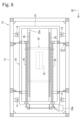
- FIG. 8 is a schematic partial cross-sectional view taken along line DD of FIG. (Example 1)
- FIG. 1 is a schematic diagram showing the overall configuration.
- FIG. 2 is a schematic diagram of the essential parts of the stretch sheet manufacturing apparatus.
- FIG. 3 is a cross-sectional view of an elastic sheet.
- FIG. 4 is a schematic front view of a storage device for elastic sheets.
- 5 is a schematic
- FIG. 9 is a schematic diagram of a main part of a storage device for elastic sheets.
- FIG. 10 is a schematic diagram of a main portion of a storage device for elastic sheets.
- FIG. 11 is a timing chart showing the operation of the elastic sheet storage device.
- FIG. 12 is a schematic view looking along line XX of FIG. (Example 1)
- FIG. 13 is a schematic diagram of a storage device for elastic sheets. (Conventional example 1)
- Embodiment 1 A method and apparatus for storing elastic sheets of Embodiment 1 will be described with reference to FIGS. 1 to 12.
- FIG. 1 A method and apparatus for storing elastic sheets of Embodiment 1 will be described with reference to FIGS. 1 to 12.
- FIG. 1 A method and apparatus for storing elastic sheets of Embodiment 1 will be described with reference to FIGS. 1 to 12.
- FIG. 1 A method and apparatus for storing elastic sheets of Embodiment 1 will be described with reference to FIGS. 1 to 12.
- Fig. 1 is a schematic diagram showing the overall configuration. As shown in FIG. 1, a stretchable sheet, that is, a stretchable sheet 2 is supplied in a stretched state from a stretchable sheet manufacturing device 200 to a stretchable sheet storage device 10 .
- the stretch sheet storage device 10 has a plurality of rolls including transport rolls 21b and 31g (some of the rolls 11a, 21a to 21c, and 31e to 31g are shown in FIG. 1) arranged along the transport path of the stretch sheet 2. It is The transport rolls 21 b and 31 g are rotationally driven by a motor, receive and transport the stretchable sheet 2 , and regulate the transport speed of the stretchable sheet 2 . That is, the transport rolls 21b and 31g transport the elastic sheet 2 in contact with the outer peripheral surfaces of the transport rolls 21b and 31g at the same transport speed as the peripheral speed of the transport rolls 21b and 31g.
- the elastic sheet storage device 10 further includes an elastic sheet discharging device 32 .
- the stretchable sheet discharging device 32 has an introduction port 32s into which the stretchable sheet 2 conveyed by the conveying rolls 21b and 31g is introduced, and a discharge port 32t into which the stretchable sheet 2 is discharged.
- the elastic sheet 2 is conveyed from the introduction port 32s to the discharge port 32t.
- the stretchable sheet discharging device 32 swings in the direction indicated by the arrow 32r, and reciprocates between the position indicated by the solid line and the position indicated by the dashed line.
- the discharge port 32t of the stretchable sheet discharge device 32 reciprocates in the direction of sandwiching both sides of the stretchable sheet 2, and the stretchable sheet 2e continuously discharged from the discharge port 32t is bent in a zigzag shape, and the stretchable sheet discharge device 32
- the elastic sheet 2s is folded and piled up on a pallet (not shown) arranged below the discharge port 16b.
- the stretch sheet 2 is manufactured by the stretch sheet manufacturing apparatus 200 and supplied to the stretch sheet storage apparatus 10 .
- the transport speed of the stretch sheet 2 when it is supplied from the stretch sheet manufacturing apparatus 200 to the stretch sheet storage device 10 is V 0
- the peripheral speed of the transport roll 21 b on the upstream side in the transport direction, that is, the transport roll 21 b is the stretch sheet 2 .
- V 1 is the transport speed for transporting the elastic sheet 2
- V 2 is the transport speed for transporting the stretch sheet 2 by the transport roll 31g on the downstream side, that is, the transport speed for transporting the stretch sheet 2 by the transport roll 31g
- V 2 is the transport speed for transporting the stretch sheet 2 by the stretch sheet discharge device 32.
- the transport rolls 21b and 31g and the elastic sheet discharging device 32 are driven so as to satisfy the following equation (1).
- the conveying rolls 21b and 31g and the elastic sheet discharging device 32 are driven so as to satisfy the following equations 2 to 4.
- V1 0.8 x V0 (equation 2)
- V2 0.6 x V0 (equation 3)
- V3 0.5 x V0 (equation 4)
- the stretchable sheet discharging device 32 By setting the conveying speed V3 at which the stretchable sheet discharging device 32 conveys the stretchable sheet 2 to be smaller than the conveying speeds V1 and V2 at which the conveying rolls 21b and 31g convey the stretchable sheet 2, the stretchable sheet discharging device 32
- the stretch rate of the stretch sheet 2 during transportation can be made smaller than the stretch rate of the stretch sheet 2 when the stretch sheet storage device 10 receives the stretch sheet 2 from the stretch sheet manufacturing device 200 .
- the elongation rate is defined as ⁇ L/L, for example, where L is the natural length when no tension is applied from the outside, and L+ ⁇ L is the length when the natural length is elongated under tension. As the elongation rate becomes smaller, the tension acting on the stretchable sheet 2 also becomes smaller.
- the stretchable sheet discharging device 32 conveys the stretchable sheet 2 having a smaller elongation rate than when it was supplied to the stretchable sheet storage device 10 , so that the stretchable sheet 2 is released when discharged from the discharge port 32 t of the stretchable sheet discharging device 32 .
- the tension of the stretchable sheet 2 can be reduced. Reducing the tension of the stretchable sheet 2 released from the discharge port 32t of the stretchable sheet discharging device 32 suppresses rapid shrinkage of the stretchable sheet 2e when discharged from the discharge port 32t of the stretchable sheet discharging device 32. Then, the stretchable sheet 2e can be stably discharged in a desired direction from the discharge port 32t of the stretchable sheet discharging device 32.
- the elastic sheet 2s can be folded and stacked on top.
- the elastic sheet storage device 10 must be equipped with at least one transport roll 21b and an elastic sheet discharging device 32, and other rolls and the like can be omitted.
- the transport rolls 21b and 31g are arranged with an interval therebetween, and the transport roll 31g on the downstream side in the transport direction transports the stretch sheet 2.
- the conveying speed V2 is made smaller than the conveying speed V1 at which the stretchable sheet 2 is conveyed by the conveying roll 21b on the upstream side in the conveying direction.
- the tension of the stretchable sheet 2 is gradually reduced, so that the stretchable sheet 2 can be easily transported stably. Therefore, it becomes easy to increase the conveying speeds V 0 , V 1 , and V 3 of the stretchable sheet 2 on the upstream side of the stretchable sheet discharging device 32 .
- the stretchable sheet discharging device 32 and the like of the stretchable sheet storage device 10 are configured to rise to the position indicated by the dashed line and protrude from the body frame 12 as indicated by the arrow 32x. Thereby, 2 s of elastic sheets can be piled up more highly.
- the placing portion for folding and stacking the elastic sheets 2s may be configured to descend, or the placing portion may remain stationary.
- the stretchable sheet discharging device 32 is preferably configured to reciprocate also in the direction perpendicular to the plane of FIG.
- the discharge port 32t of the stretchable sheet discharging device 32 reciprocates in the first direction in which both sides of the stretchable sheet 2 are sandwiched, and in the second direction in which the stretchable sheet 2 is conveyed while being sandwiched between the stretchable sheet discharging devices. reciprocates in a third direction that intersects with the first direction.
- FIG. 2 is a schematic diagram of the essential parts of the stretch sheet manufacturing apparatus 200.
- a stretch sheet manufacturing apparatus 200 heats and melts an elastic resin material whose main component is an elastic thermoplastic elastic resin by means of an extruder 210, and extrudes the material from the outlet of a die 212.
- a resin film 8 is formed by extruding in a planar shape and cooling with cooling rolls 220 and 222 .
- the resin film 8 is stretched in the conveying direction 8x, and the stretched resin film 8 is placed and laminated between two sheet members 4 and 6 conveyed in the directions of arrows 4x and 6x. to form a laminate 2z.
- the sheet members 4 and 6 are, for example, nonwoven fabric sheets.
- the laminated body 2z is conveyed along the anvil roll 230, and the stretched resin film 8 and the sheet members 4, 6 are welded by using an ultrasonic horn 232.
- the elastic sheet 2 may be formed by welding by heat sealing.
- the stretchable sheet 2 is conveyed in the direction indicated by the arrow 2x with the resin film 8 stretched, and supplied to the stretchable sheet storage device 10 with the resin film 8 stretched.
- FIG. 3(a) is a schematic cross-sectional view of the stretch sheet 2 formed by the stretch sheet manufacturing apparatus 200.
- FIG. By periodically welding using an ultrasonic horn 232, as shown in FIG. It is formed with L1.
- FIG. 3(b) is a schematic cross-sectional view of the elastic sheet 2 when the stretched state is released. As shown in FIG. 3(b), when the stretched state is released, the resin film 8 shrinks, the gap L2 between the joints 3 becomes shorter than the gap L1 in the stretched state, and the sheet members 4, 6 A deflection is formed.
- the resin film 8 is made of an elastic resin material whose main component is an elastic thermoplastic elastic resin, and has elasticity. Therefore, the elastic sheet 2, which has been released from the stretched state, stretches when pulled and shrinks when the pulling is stopped. That is, the stretchable sheet 2 is stretchable.
- the stretchable sheet 2 may be laminated with the sheet member 4 or 6 arranged only on one side of the resin film 8, but as shown in FIG. By doing so, the appearance of both sides of the elastic sheet 2 can be made uniform.
- the stretching device manufacturing apparatus 200 starts forming the resin film 8 and sandwiches the resin film 8 between the sheet members 4 and 6 to form the stretching sheet 2 .
- the stretch sheet 2 is conveyed by the stretch sheet discharging device 32 at a conveying speed V 3 in the same manner as in the steady operation state. are made smaller than the conveying speeds V 1 and V 2 of the stretchable sheet 2 by the conveying rolls 21b and 31g.
- V 1 , V 2 , and V 3 have the same speed and that the tension acting on the sheet members 4 and 6 at the stage of supplying to the storage device 10 is larger than that during steady operation. This is because when the resin film 8 is not present, there are only two sheet members 4 and 6, so there is no stretchability, and the conveying speeds V 0 , V 1 , V 2 , V 3 of the conveying rolls etc. are different. This is to prevent the sheet members 4 and 6 from being slackened and entangled with the conveying rolls or the like.
- the stretch sheet storage method includes first and second conveying steps.
- the stretchable sheet 2 is received in a stretched state and transported to the stretchable sheet discharging device 32 . At this time, the stretchable sheet 2 is transported using the transport rolls 21b and 31g that regulate the transport speed of the stretchable sheet 2 .
- the stretchable sheet discharging device 32 conveys the stretchable sheet 2 from the inlet 32s of the stretchable sheet discharging device 32 to the discharging port 32t while sandwiching both sides of the stretchable sheet 2.
- 32 discharge port 32t is reciprocated in the first direction sandwiching both sides of the stretchable sheet 2, and the stretchable sheets 2s discharged from the discharge port 32t of the stretchable sheet discharging device 32 are folded and piled up.
- the conveying speed V3 at which the stretchable sheet 2 is conveyed by the stretchable sheet discharging device 32 while sandwiching the stretchable sheet 2 is changed to the conveying speed V1 at which the conveying rolls 21b and 31g convey the stretchable sheet 2 in the first conveying step. Make it smaller than V2 .
- the stretchable sheet 2e can be stably discharged in a desired direction from the discharge port 32t of the stretchable sheet discharge device 32, and the stretchable sheet 2 can be folded under the discharge port 32t of the stretchable sheet discharge device 32. can be stacked.
- the stretchable sheet 2 is conveyed by a plurality of conveying rolls 21b and 31g arranged at intervals along the conveying path of the stretchable sheet 2, and the conveying roll 31g on the downstream side in the conveying direction is the stretchable sheet. 2 is made smaller than the transport speed V1 at which the stretchable sheet 2 is transported by the transport roll 21b on the upstream side in the transport direction.
- the tension of the stretchable sheet 2 is reduced step by step, so that the conveying speed on the upstream side of the stretchable sheet 2 can be easily increased, and the production efficiency of the stretchable sheet 2 can be easily increased.
- the stretch sheet 2 is conveyed in the first direction and sandwiched between the stretch sheet discharge device 32 while reciprocating the discharge port 32t of the stretch sheet discharge device 32 in the first direction. Reciprocating movement is performed in a third direction intersecting the two directions. In this case, since the range of stacking the stretchable sheets 2s is widened, a larger amount of the stretchable sheets 2s can be stored.
- An elastic resin material whose main component is a thermoplastic elastic resin having elasticity is extruded in a heated and melted state to form a resin film 8, and the resin film 8 is stretched.
- a stretchable film forming step of forming the stretchable sheet 2 by laminating the stretchable sheet members 4 and 6 in the folded state is further provided.
- the elastic sheet 2 can be formed continuously and folded and stacked.
- the stretched resin film 8 and the sheet members 4 and 6 are intermittently welded. In this case, it is possible to form a stretchable sheet in which the sheet members 4 and 6 are flexed when the stretched state is released.
- the stretchable sheet 2 is formed by laminating the resin film 8 and the sheet members 4 and 6 so that the resin film 8 is arranged between the two sheet members 4 and 6 . In this case, the appearance of both sides of the stretchable sheet 2 can be uniformed.
- the elastic sheet storage device 10 will be described in more detail below with reference to FIGS. 4 to 12.
- FIG. 1 is a diagrammatic representation of the elastic sheet storage device 10.
- FIG. 4 is a schematic front view of the elastic sheet storage device 10.
- FIG. 5 is a schematic side view looking along line AA of FIG. 4.
- FIG. 6 is a schematic view looking along line BB of FIG.
- FIG. 7 is a schematic top view taken along line CC of FIG. 5, showing the track shifter 40 in perspective.
- 8 is a schematic partial cross-sectional view taken along line DD of FIG. 7.
- FIG. 9 is a schematic diagram of the essential part of the elastic sheet storage device 10 .
- the elastic sheet storage device 10 includes a first moving unit 20, a second moving unit 30, and an elastic sheet discharging device 32. As shown in FIGS. Inside the body frame 12 of the elastic sheet storage device 10, there are provided a pallet placing device 16 for placing the pallet 5 in the placing area 6, a first moving unit 20, a second moving unit 30, and an elastic sheet discharge. A device 32 and the like are arranged.
- the elastic sheet storage device 10 folds and stacks the elastic sheets discharged from the elastic sheet discharge device 32 on the pallet 5 arranged in the placement area 6 .
- the pallet placing device 16 conveys the pallet 5 on which the elastic sheets are piled up from the placing area 6 to a take-out position (not shown).
- the placing area 6 is a predetermined area in which the pallet 5 is placed when the elastic sheet discharged from the elastic sheet discharging device 32 is folded and stacked on the pallet 5 .
- the elastic sheet storage device 10 conveys the elastic sheets 2 that are continuous in the longitudinal direction, and folds and stacks the elastic sheets 2 on the pallet 5 .
- the elastic sheet 2 is a single-layer or multi-layer sheet.
- a multi-layered sheet in which an elastic resin film is sandwiched between two nonwoven fabric sheets and the resin film and the nonwoven fabric sheet are bonded to each other. It is a sheet consisting of
- the first moving unit 20 is arranged above the mounting area 6 and configured to move up and down along the body frame 12 in a third direction 83 facing the mounting area 6 as indicated by an arrow 83 . It is Specifically, the body frame 12 rotatably supports the first screw shaft 14 extending in the third direction 83 , and the moving member 22 of the first moving unit 20 is engaged with the first screw shaft 14 . are in agreement. The moving member 22 of the first moving unit 20 translates in the third direction 83 by rotating the first screw shaft 14 by the first motor 14m. Also, the wheels 23 rotatably supported by the first moving unit 20 are engaged with the first rails 13 fixed to the body frame 12 and extending in the third direction 83, move along.
- a track shifter 40 is arranged on the top of the first moving unit 20 so as to be able to swing.
- a track shifter 40 is arranged above the second moving unit 30 .
- a receiving roll 40p for receiving the stretchable sheet 2 is rotatably supported at one end of a frame 40k having a U-shaped cross section, and a discharging roll for discharging the received stretchable sheet 2 at the other end. 40q is rotatably supported.
- the first moving unit 20 supports a plurality of first rolls 21a-21c. These first rolls 21a to 21c define a first transport path 2p along which the elastic sheet 2 guided by the guide roll 11a supported by the body frame 12 is transported to the receiving roll 40p of the track shifter 40. .
- the second moving unit 30 is supported by the first moving unit 20 and configured to reciprocate along the placement area 6 in a first direction 81 indicated by an arrow 81 .
- a pair of second rails 25 are fixed to the upper surface 22a of the horizontally extending moving member 22 of the first moving unit 20, and a pair of second screws are provided.
- a shaft 26 is rotatably supported by the moving member 22 .
- the second rail 25 and the second screw shaft 26 extend in the first direction 81 .
- a second wheel 37 of the second moving unit 30 is engaged with the second rail 25 , and an engaging portion 36 of the second moving unit 30 is engaged with the second screw shaft 26 .
- the second moving unit 30 moves in the first direction 81 by rotating the second screw shaft 26 by the second motor 26m.
- the second moving unit 30 supports the upper part of the elastic sheet discharging device 32 so as to be swingable.
- the elastic sheet discharging device 32 is swung between first and second positions 32p and 32q indicated by dashed lines 32p and 32q in FIG. 4 by a third motor 32m.
- the discharge port 32t provided in the lower part of the stretchable sheet discharge device 32 reciprocates along the placement area 6 in a second direction 82 orthogonal to the first direction 81. .
- the discharge port 32 t discharges the stretch sheet 2 toward the placement area 6 so that the width direction of the stretch sheet 2 is parallel to the first direction 81 .
- two transport conveyors 33a and 33b are arranged mirror-symmetrically.
- the transport conveyors 33a and 33b circulate in the direction indicated by the arrow 33x with the endless belt 33v along the guide rollers 33p and 33q and the driving roller 33d.
- the stretchable sheet 2 is conveyed while being sandwiched between the endless belts 33v of the conveyers 33a and 33b, and the discharge port 32t between the ends of the endless belts 33v of the conveyers 33a and 33b facing each other in the conveying direction. , in the direction indicated by the arrow 2x.
- the driving rollers 33d of the conveyers 33a and 33b are rotationally driven by the conveyer motors 33m and 33n shown in FIG.
- the second moving unit 30 supports a plurality of second rolls 31a to 31g defining a second conveying path 2q along which the stretchable sheet 2 is conveyed from the discharge roll 40q of the track shifter 40 to the stretchable sheet discharging device 32. ing.
- the second moving unit 30 is provided with pressing members 34 that move reversibly toward the placing area 6 on both sides of the stretchable sheet discharging device 32 in the first direction 81 .
- the pressing member 34 is a plate-like member, and is moved from a standby position 34p to a pressing position 34q by expansion and contraction of an air cylinder 35 fixed to the second moving unit 30, as indicated by chain lines 34p and 34q in FIG. , and presses the elastic sheet 2s folded on the pallet 5.
- the pressing member 34 can be provided in the first moving unit 20 , but if it is provided in the second moving unit 30 , the pressing member 34 can be easily configured so as not to interfere with the stretchable sheet discharging device 32 . be.
- the pressing member 34 may be omitted.
- the track shifter 40 is configured to swing in response to this deviation.
- an arcuately curved guide member 42 is fixed via a support member 41 to the upper surface 24a of the upper member 24 of the first moving unit 20, and the third is rotatably supported by the upper member 24 .
- the third screw shaft 46 extends in the first direction 81 .
- an engaging member 47 is engaged with the third screw shaft 46, and the engaging member 47 is formed with a projection 47a projecting upward.
- two pairs of nipping rollers 44a and 44b for nipping an arcuate guide member 42 from the radially inner and outer sides below one end of a frame 40k of the track shifter 40; 44p and 44q are rotatably supported.
- the holding members 48a and 48b are fixed.
- the engaging member 47 moves along the third screw shaft 46.
- the track shifter 40 swings as indicated by oblique lines 40a and 40b in FIG.
- the track shifter 40 swings on the upstream side of the receiving roll 40p around a predetermined point 40x in the widthwise center of the receiving roll 40p so that the center line of the stretchable sheet 2 received by the receiving roll 40p does not move.
- the track shifter 40 follows the movement of the second moving unit 30 in the first direction 81 and swings so that the discharge roll 40q moves in the first direction 81.
- the stretchable sheet 2 is twisted.
- the first transport path 2p on the upstream side of the track shifter 40 is bent using the first rolls 21a to 21c supported by the first moving unit 20 to form the first transport path.
- the second transport path 2q from the track shifter 40 to the stretchable sheet discharging device 32 is bent using the second rolls 31a to 31g supported by the second moving unit 30, thereby forming the second transport path. Make it long enough. Thereby, even if the 2nd moving unit 30 moves, the elastic sheet 2 can be conveyed stably.
- the first and second transport paths 2p and 2q can be bent while suppressing an increase in dimensions such as height and width of the elastic sheet storage device 10. can be long enough.
- FIG. 10 Next, the operation of the elastic sheet storage device 10 will be described with reference to FIGS. 10 to 12.
- FIG. 10 is a diagrammatic representation of the elastic sheet storage device 10.
- FIG. 10 is a schematic diagram of the essential parts showing the operation of the storage device 10 for elastic sheets.
- the elastic sheet discharging device 32 when the operation is started, the elastic sheet discharging device 32 repeatedly swings between the position indicated by the solid line and the position indicated by the chain line.
- the stretchable sheet 2 is conveyed in the direction indicated by the arrow 2i in the stretchable sheet storage device 10, passes through the stretchable sheet discharging device 32, and is discharged from the discharge port 32t that reciprocates in the second direction 82.
- the elastic sheet 2 s is folded and stacked on the pallet 5 placed on the pallet placing device 16 .
- the first moving unit 20 rises appropriately so that the discharge port 32t of the stretchable sheet discharging device 32 is separated from the stretchable sheets 2s folded and stacked on the pallet 5 with an appropriate gap.
- the pressing member 34 presses the elastic sheets 2 s folded and stacked on the pallet 5 .
- FIG. 11 is a timing chart showing an example of the operation of the storage device 10 for stretchable sheets.
- the stretchable sheet discharging device 32 repeats swinging at a constant cycle.
- the second motor 26 m rotates in one direction to move the second moving unit 30 in the first direction 81 .
- the second moving unit 30 moves to the second motor 26m stops rotating in one direction, and the second moving unit 30 stops at the first position. After that, the same operation is repeated.
- N1, N2, K1, and K2 may be natural numbers, positive real numbers other than natural numbers, or N1 ⁇ N2 and K1 ⁇ K2.
- the movement of the second mobile unit 30 can be reduced, which is preferable.
- the discharge port of the elastic sheet discharging device 32 is moved in the second direction 82 along the placing area 6.
- the number of reciprocating movements of 32t becomes two or more, and the movement of the second moving unit 30 can be reduced.
- the first moving unit 20 rises and the pressing member 34 operates as follows.
- the air cylinder 35 When the second moving unit 30 moves and stops at the first position, the air cylinder 35 is turned on and the pressing member 34 descends, as indicated by reference numeral 60 . Then, as indicated by reference numeral 62, the air cylinder 35 is turned off, and the pressing member 34 rises and returns to its original position.
- the air cylinder 35 is turned on and the pressing member 34 descends, as indicated by reference numeral 64 . Then, as indicated by reference numeral 66, the air cylinder is turned off and the pressing member 34 is lifted.
- FIG. 12 is a schematic view taken along the line XX in FIG. 10, and schematically illustrates the folded portions 2v of the elastic sheet 2s folded on the pallet 5 by solid lines 2a to 2d.
- the stretchable sheet discharging device 32 moves and swings in the direction indicated by the arrow 32x.
- the first intermediate folded portions 2b and 2c are formed in which the elastic sheet is newly folded.
- the pressing member 34 descends to press and compress the first folded portion 2a.
- the wavy portion between the facing folded portions 2u and 2v of the elastic sheet 2k shown in FIG. 10 is pressed and flattened.
- the elastic sheet is newly folded on the other side of the pallet 5 in the first direction 81 .
- the stretchable sheet discharging device 32 swings, thereby forming the second stretchable sheet in which the stretchable sheet is newly folded.
- a folded portion 2 d is formed on the other side of the pallet 5 in the first direction 81 .
- the second moving unit 30 stops at the first position and the second position so that the first folded portion 2a and the second folded portion 2d are adjacent to each other without overlapping. That is, the second moving unit 30 stops at a plurality of locations, i.e., the first position and the second position, in the first direction 81 at intervals equal to or greater than the dimension W in the width direction of the stretchable sheet 2 . .
- the portions 2a and 2d where the sheet is folded when the second moving unit 30 is stopped are the pallet. 5 can be formed at multiple locations 4a, 4b. Since the portions 2a and 2d that fold over when the second moving unit 30 is stopped are connected to each other via the portions 2b and 2c that fold over when the second moving unit 30 is moving, It is possible to stack the elastic sheet higher than when the elastic sheet is folded only at one place.
- the replacement frequency of the pallet 5 can be reduced as compared with the case where the stretchable sheet 2s is folded and stacked at only one position on the pallet 5. can be reduced.
- the pressing member 34 can press the folded stretchable sheet 2s to straighten the stretchable sheet 2s.
- the stretchable sheets 2s can be stacked higher and the total length of the stretchable sheets 2s that can be folded and stacked can be increased, and the frequency of pallet replacement can be further reduced.
- the pallet 5 is taken out and another pallet 5 is placed on the pallet placing device 16 .
- Another pallet 5 placed on the pallet placing device 16 does not need to be raised to a predetermined height, so the operation interruption time associated with pallet replacement can be shortened.
- the second moving unit 30 stops at three or more places, so that the stretchable sheet is folded while the second moving unit 30 is stopped. It is possible to form three or more portions on the pallet 5. In this case as well, the second moving unit 30 stops at a plurality of locations in the first direction 81 at intervals equal to or greater than the dimension W in the width direction of the stretchable sheet.
- the case where the second direction 82 is orthogonal to the first direction 81 is exemplified. It is also possible to configure the elastic sheet storage device 10 so that it is in a cross direction. Further, in Example 1, the case where the stretchable sheet 2 is discharged from the discharge port 32t of the stretchable sheet discharging device 32 so that the width direction of the stretchable sheet 2 coincides with the first direction 81 was exemplified. The elastic sheet storage device 10 is configured so that the elastic sheet 2 is discharged from the outlet 32t so that the width direction of the elastic sheet 2 intersects the second direction 82 instead of coinciding with the first direction 81. is also possible.
- the discharge port 32t of the stretchable sheet discharge device 32 reciprocates in the second direction 82 without the stretchable sheet discharge device 32 swinging. It may be configured to move.
- the elastic sheet storage device 10 can be operated in various ways.
- the first mobile unit 20 may continue to move instead of repeatedly moving and stopping.
- the movement and stopping of the second moving unit 30 and the reciprocating movement of the discharge port 32t can be interlocked in various manners.
- the stretchable sheet 2 can be folded and stacked while being conveyed in a stretched state.
- the stretchable sheet discharging device can be configured such that the stretchable sheet is sandwiched between rollers or the like without using an endless belt.
- the stretch sheet storage device can be configured to transport stretch sheets of various configurations.
Landscapes
- Engineering & Computer Science (AREA)
- Mechanical Engineering (AREA)
- Textile Engineering (AREA)
- Folding Of Thin Sheet-Like Materials, Special Discharging Devices, And Others (AREA)
Priority Applications (4)
| Application Number | Priority Date | Filing Date | Title |
|---|---|---|---|
| EP22915929.8A EP4438537A1 (en) | 2021-12-28 | 2022-12-22 | Method and device for storing stretchable sheet |
| JP2023570948A JPWO2023127706A1 (https=) | 2021-12-28 | 2022-12-22 | |
| CN202280085935.7A CN118434659A (zh) | 2021-12-28 | 2022-12-22 | 可伸缩片材的收纳方法和装置 |
| US18/719,275 US20250128904A1 (en) | 2021-12-28 | 2022-12-22 | Method and device for storing stretchable sheet |
Applications Claiming Priority (2)
| Application Number | Priority Date | Filing Date | Title |
|---|---|---|---|
| JP2021-214553 | 2021-12-28 | ||
| JP2021214553 | 2021-12-28 |
Publications (1)
| Publication Number | Publication Date |
|---|---|
| WO2023127706A1 true WO2023127706A1 (ja) | 2023-07-06 |
Family
ID=86999148
Family Applications (1)
| Application Number | Title | Priority Date | Filing Date |
|---|---|---|---|
| PCT/JP2022/047496 Ceased WO2023127706A1 (ja) | 2021-12-28 | 2022-12-22 | 伸縮シートの貯留方法及び装置 |
Country Status (5)
| Country | Link |
|---|---|
| US (1) | US20250128904A1 (https=) |
| EP (1) | EP4438537A1 (https=) |
| JP (1) | JPWO2023127706A1 (https=) |
| CN (1) | CN118434659A (https=) |
| WO (1) | WO2023127706A1 (https=) |
Citations (5)
| Publication number | Priority date | Publication date | Assignee | Title |
|---|---|---|---|---|
| JP2003285971A (ja) * | 2002-03-28 | 2003-10-07 | Fuji Xerox Co Ltd | プリンタの後処理装置用評価用紙 |
| JP2012041171A (ja) * | 2010-08-23 | 2012-03-01 | Bridgestone Corp | 帯状ゴム部材の折畳み積載方法および装置 |
| JP2012236704A (ja) | 2011-05-13 | 2012-12-06 | Bridgestone Corp | シート状部材の積載方法及び積載装置 |
| WO2020090753A1 (ja) | 2018-10-29 | 2020-05-07 | 株式会社瑞光 | 積層体の製造方法および製造装置 |
| JP2021134045A (ja) * | 2020-02-27 | 2021-09-13 | 株式会社瑞光 | 伸縮シートの製造方法および装置 |
-
2022
- 2022-12-22 CN CN202280085935.7A patent/CN118434659A/zh active Pending
- 2022-12-22 WO PCT/JP2022/047496 patent/WO2023127706A1/ja not_active Ceased
- 2022-12-22 US US18/719,275 patent/US20250128904A1/en active Pending
- 2022-12-22 JP JP2023570948A patent/JPWO2023127706A1/ja not_active Abandoned
- 2022-12-22 EP EP22915929.8A patent/EP4438537A1/en not_active Withdrawn
Patent Citations (5)
| Publication number | Priority date | Publication date | Assignee | Title |
|---|---|---|---|---|
| JP2003285971A (ja) * | 2002-03-28 | 2003-10-07 | Fuji Xerox Co Ltd | プリンタの後処理装置用評価用紙 |
| JP2012041171A (ja) * | 2010-08-23 | 2012-03-01 | Bridgestone Corp | 帯状ゴム部材の折畳み積載方法および装置 |
| JP2012236704A (ja) | 2011-05-13 | 2012-12-06 | Bridgestone Corp | シート状部材の積載方法及び積載装置 |
| WO2020090753A1 (ja) | 2018-10-29 | 2020-05-07 | 株式会社瑞光 | 積層体の製造方法および製造装置 |
| JP2021134045A (ja) * | 2020-02-27 | 2021-09-13 | 株式会社瑞光 | 伸縮シートの製造方法および装置 |
Also Published As
| Publication number | Publication date |
|---|---|
| EP4438537A1 (en) | 2024-10-02 |
| CN118434659A (zh) | 2024-08-02 |
| US20250128904A1 (en) | 2025-04-24 |
| JPWO2023127706A1 (https=) | 2023-07-06 |
Similar Documents
| Publication | Publication Date | Title |
|---|---|---|
| JP6219833B2 (ja) | 関連する封止済みパックから注入可能食品の折曲げ済みパッケージを製造するための折曲げユニット | |
| US9902566B2 (en) | Conveyor for an article handling unit, in particular for a folding unit for producing packages of pourable food products | |
| JP4528822B2 (ja) | 紙製綴じ具、および、その製造システムと製造装置 | |
| EP2586716B1 (en) | Folding unit for pourable food product packaging machines | |
| CN1368934A (zh) | 用于传输和折叠挠性包装材料的装置 | |
| CN1203877A (zh) | 用以从一包装材料管连续生产密封包装的包装装置 | |
| WO2013064287A1 (en) | Folding unit and method for producing pourable food product packages | |
| WO2022213592A1 (zh) | 四边封立体袋包装机 | |
| WO2023127706A1 (ja) | 伸縮シートの貯留方法及び装置 | |
| IT201800006936A1 (it) | Apparecchiatura e metodo per il confezionamento di prodotti | |
| JP7319657B2 (ja) | ピロー包装機および通紙方法 | |
| JP6669431B2 (ja) | 包装機 | |
| KR200468962Y1 (ko) | 냅킨 자동 포장장치 | |
| CN201172292Y (zh) | 夹链线贴合机 | |
| JP2002193215A (ja) | 製袋充填包装機の縦シール装置 | |
| KR200247260Y1 (ko) | 포장용 종이앵글의 연속 성형장치 | |
| JP6080120B2 (ja) | センターシール装置及びピロー包装機 | |
| WO2023068003A1 (ja) | シート折り畳み装置 | |
| CN216832278U (zh) | 一种袖套机热封装置 | |
| CN210940669U (zh) | 一种裱纸机的压合传送装置 | |
| JPWO2023127706A5 (https=) | ||
| JP5090067B2 (ja) | 溶融樹脂の搬送装置 | |
| JP2009083357A (ja) | シート成形設備 | |
| CN116160716A (zh) | 一种包装纸箱侧面提扣自动化处理装置 | |
| JP2017109841A (ja) | 搬送装置 |
Legal Events
| Date | Code | Title | Description |
|---|---|---|---|
| 121 | Ep: the epo has been informed by wipo that ep was designated in this application |
Ref document number: 22915929 Country of ref document: EP Kind code of ref document: A1 |
|
| WWE | Wipo information: entry into national phase |
Ref document number: 18719275 Country of ref document: US |
|
| WWE | Wipo information: entry into national phase |
Ref document number: 2023570948 Country of ref document: JP |
|
| WWE | Wipo information: entry into national phase |
Ref document number: 202280085935.7 Country of ref document: CN |
|
| ENP | Entry into the national phase |
Ref document number: 2022915929 Country of ref document: EP Effective date: 20240625 |
|
| NENP | Non-entry into the national phase |
Ref country code: DE |
|
| WWP | Wipo information: published in national office |
Ref document number: 18719275 Country of ref document: US |