WO2023127528A1 - 光ファイバ集合体及び光ケーブル - Google Patents
光ファイバ集合体及び光ケーブル Download PDFInfo
- Publication number
- WO2023127528A1 WO2023127528A1 PCT/JP2022/046227 JP2022046227W WO2023127528A1 WO 2023127528 A1 WO2023127528 A1 WO 2023127528A1 JP 2022046227 W JP2022046227 W JP 2022046227W WO 2023127528 A1 WO2023127528 A1 WO 2023127528A1
- Authority
- WO
- WIPO (PCT)
- Prior art keywords
- optical fiber
- optical
- unit
- assembly
- tape
- Prior art date
- Legal status (The legal status is an assumption and is not a legal conclusion. Google has not performed a legal analysis and makes no representation as to the accuracy of the status listed.)
- Ceased
Links
Images


Classifications
-
- G—PHYSICS
- G02—OPTICS
- G02B—OPTICAL ELEMENTS, SYSTEMS OR APPARATUS
- G02B6/00—Light guides; Structural details of arrangements comprising light guides and other optical elements, e.g. couplings
- G02B6/44—Mechanical structures for providing tensile strength and external protection for fibres, e.g. optical transmission cables
- G02B6/4401—Optical cables
- G02B6/4429—Means specially adapted for strengthening or protecting the cables
- G02B6/4434—Central member to take up tensile loads
-
- G—PHYSICS
- G02—OPTICS
- G02B—OPTICAL ELEMENTS, SYSTEMS OR APPARATUS
- G02B6/00—Light guides; Structural details of arrangements comprising light guides and other optical elements, e.g. couplings
- G02B6/44—Mechanical structures for providing tensile strength and external protection for fibres, e.g. optical transmission cables
- G02B6/4401—Optical cables
- G02B6/4403—Optical cables with ribbon structure
-
- G—PHYSICS
- G02—OPTICS
- G02B—OPTICAL ELEMENTS, SYSTEMS OR APPARATUS
- G02B6/00—Light guides; Structural details of arrangements comprising light guides and other optical elements, e.g. couplings
- G02B6/44—Mechanical structures for providing tensile strength and external protection for fibres, e.g. optical transmission cables
- G02B6/4439—Auxiliary devices
- G02B6/4471—Terminating devices ; Cable clamps
- G02B6/4478—Bending relief means
Definitions
- the present invention relates to optical fiber assemblies and optical cables. This application claims priority based on Japanese Patent Application No. 2021-212173 filed in Japan on December 27, 2021, the content of which is incorporated herein.
- an optical fiber unit (tape fiber unit) is configured by stacking and bundling a plurality of optical fiber tapes, and a cable core (optical fiber assembly) is provided by assembling a plurality of the optical fiber units.
- a fiber optic cable (optical cable) is disclosed.
- an optical cable having the above-described optical fiber assembly is manufactured without any measures, if the optical cable is bent or if the jacket of the optical cable shrinks in a low-temperature environment, the optical fibers of a specific optical fiber unit may be damaged. Stresses (mainly bending stresses) are often concentrated. There is a problem that when stress concentrates on a specific optical fiber, the transmission loss of the optical fiber increases. Also, in recent years, there has been a demand for optical fiber cables having more optical fibers. Therefore, it is required to arrange more optical fiber units in the limited internal space of the optical fiber assembly. That is, there is a demand for improving the utilization efficiency of the internal space of the optical fiber assembly by the optical fiber unit.
- the present invention has been made in view of the circumstances described above, and is capable of suppressing an increase in the transmission loss of optical fibers and improving the utilization efficiency of the internal space in which a plurality of optical fiber units are arranged. It is an object of the present invention to provide a possible optical fiber assembly and an optical cable comprising the same.
- An optical fiber assembly is an optical fiber assembly configured by bundling a plurality of optical fiber units each formed by laminating a plurality of optical fiber tapes, wherein at least the longitudinal direction of the optical fiber assembly is In the cross section of the optical fiber assembly orthogonal to the longitudinal direction at a certain position in the direction, the tape surface of at least one of the optical fiber tapes constituting the optical fiber unit is curved.
- the laminated state of the optical fiber tape is broken, and the plurality of optical fiber units includes a first fiber positioned on a neutral line of bending of the optical fiber assembly in a cross section of the optical fiber assembly perpendicular to the longitudinal direction.
- the average value of the sine values sin ⁇ of the plurality of optical fiber tapes in the same optical fiber unit is defined as the average sine value sin ⁇ ave , and at least a certain length in the longitudinal direction In a cross-section of the optical fiber assembly orthogonal to the longitudinal direction at a position, the average sine value sin ⁇ ave in the second fiber unit is greater than the average sine value sin ⁇ ave in at least one of the first fiber units.
- An optical cable according to a second aspect of the present invention includes the optical fiber assembly of the first aspect, and a imparting member that imparts bending anisotropy to the optical cable to make it easier to bend in a direction centered on the neutral line.
- the present invention it is possible to suppress an increase in optical fiber transmission loss and improve the utilization efficiency of the internal space in which a plurality of optical fiber units are arranged.
- FIG. 1 is a schematic cross-sectional view of an optical cable including an optical fiber assembly according to this embodiment
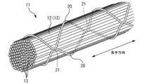
- FIG. 2 is a perspective view schematically showing an optical fiber unit included in the optical fiber assembly of FIG. 1
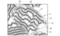
- FIG. 3 is a perspective view schematically showing an optical fiber tape included in the optical fiber unit of FIG. 2
- 3 is a diagram showing an example of a cross-sectional shape of the optical fiber unit of FIG. 2
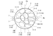
- FIG. 4 is a cross-sectional view schematically showing an example of arrangement of a plurality of optical fiber units in the optical fiber assembly according to the present embodiment
- FIG. 4 is a cross-sectional view schematically showing a comparative example of arrangement of a plurality of optical fiber units in an optical fiber assembly
- FIG. 3 is a diagram showing an angle ⁇ formed by a radial straight line R1 connecting the center C of the optical fiber assembly and the center of gravity G of the optical fiber tape, and a tape width straight line W1 connecting both ends of the optical fiber tape.
- 6 is a table showing the relationship between the average sine value sin ⁇ ave of a plurality of optical fiber units and the increase in transmission loss of the optical fiber in the embodiment of FIG. 5; 7 is a table showing the relationship between the average sine value sin ⁇ ave of a plurality of optical fiber units and the transmission loss increase amount of the optical fiber in the comparative example of FIG. 6;
- the optical fiber assembly 2 of this embodiment constitutes a part of the optical cable 1.
- the optical cable 1 of this embodiment is a so-called slotless type optical cable that does not have a slot rod in which a groove (slot) for accommodating an optical fiber is formed.
- the optical cable 1 has an optical fiber assembly 2 and a jacket 3 .
- the optical fiber assembly 2 is configured by bundling a plurality of optical fiber units 11 .
- the optical fiber unit 11 is a structure in which a plurality of optical fibers 13 are bundled. A specific structure of the optical fiber unit 11 will be described later.
- the optical fiber assembly 2 of this embodiment constitutes the core of the optical cable 1 .
- the core of the optical cable 1 of this embodiment further has a pressing tape 5 covering the plurality of optical fiber units 11 .
- the pressing tape 5 may be made of, for example, a water absorbing tape.
- the pressing tape 5 constitutes the internal space of the optical fiber assembly 2 in which the plurality of optical fiber units 11 are arranged.
- the above-described pressing tape 5 may be omitted.
- the inner surface of the jacket 3, which will be described later forms the inner space of the optical fiber assembly 2. As shown in FIG.
- the jacket 3 is formed in a tubular shape.
- the optical fiber assembly 2 is housed inside the jacket 3 .
- a plurality of optical fiber units 11 may be accommodated inside the jacket 3 in a state of being twisted in one direction or in an SZ shape, for example.
- an intervening material (not shown) may be accommodated inside the jacket 3 .
- the inclusions may be, for example, absorbent materials.
- the inclusions may be placed inside, outside, or both of the hold-down tape 5 .
- the inclusions described above may be absent, for example.
- the outer shape of the optical fiber assembly 2 in a cross section orthogonal to the longitudinal direction of the optical cable 1 may be any shape. , which is substantially circular in this embodiment.
- the substantially circular shape includes not only a perfect circular shape but also an elliptical shape, an oval shape, and the like.
- the outer shape of the optical fiber assembly 2 in the cross section described above may be, for example, a rectangular shape.
- the jacket 3 is a member that covers the optical fiber assembly 2 .
- the inner surface of the jacket 3 forms a space for accommodating the optical fiber assembly 2 .
- the inner surface of the jacket 3 has a substantially circular shape corresponding to the optical fiber assembly 2 in a cross section perpendicular to the longitudinal direction of the optical cable 1 .
- the cross-sectional shape of the inner surface of the jacket 3 may be rectangular, for example.
- a pressing tape 5 wrapping a plurality of optical fiber units 11 is housed inside the jacket 3 .
- a tension member 7 is arranged on the jacket 3 .
- the entire tension member 7 may be arranged inside the jacket 3 , or part of the tension member 7 may be arranged inside the jacket 3 and the rest of the tension member 7 may be exposed from the jacket 3 . .
- Other elements may be arranged on the jacket 3, for example ripcords.
- a plurality of tension members 7 are arranged so as to sandwich the optical fiber assembly 2 in a cross section perpendicular to the longitudinal direction of the optical cable 1 .
- the plurality of tension members 7 are arranged so as to face each other with the optical fiber assembly 2 interposed therebetween in the first direction orthogonal to the longitudinal direction.
- the other tension members are arranged so as to face each other with the optical fiber assembly 2 interposed therebetween in a second direction orthogonal to both the longitudinal direction and the first direction. is not arranged, but is not limited to this, and other tension members may be arranged so as to face each other with the optical fiber assembly 2 interposed therebetween in the second direction.
- Each tension member 7 extends in the longitudinal direction of the optical cable 1 .
- Each tension member 7 may be arranged parallel to the longitudinal direction of the optical fiber assembly 2, or may be arranged spirally with the optical fiber assembly 2 as the center. Also, each tension member 7 may be included inside the optical fiber assembly 2, for example.
- two tension members 7 are set as one set, and a pair of sets are arranged on both sides of the optical fiber assembly 2, but the arrangement is not limited to this.
- a set of three or more tension members 7 may be arranged on both sides of the optical fiber assembly 2 .
- one tension member 7 may be arranged on each side of the optical fiber assembly 2 .
- the plurality of tension members 7 forming a set are spaced apart, but they may be in contact with each other, for example.
- a plurality of tension members 7 forming a set may be twisted.
- An area in which one tension member 7 or a set of tension members 7 is arranged may be referred to as a tension member arrangement area.
- a line indicated by symbol NL in FIG. 1 indicates a bending neutral line NL of the optical cable 1 (optical fiber assembly 2) connecting the centers of the pair of tension members 7 (or tension member arrangement regions).
- the neutral line NL indicates the position of the optical cable 1 where the expansion and contraction in the longitudinal direction of the optical cable 1 is small when the optical cable 1 is bent. For example, in FIG. 1, when the optical cable 1 is bent so that the optical cable 1 protrudes upward from the neutral line NL, the portion of the optical cable 1 located above the neutral line NL extends in the longitudinal direction of the optical cable 1 and extends toward the neutral line NL. The portion of the optical cable 1 positioned below is contracted in the longitudinal direction of the optical cable 1 .
- the tension member 7 (or the tension member arrangement area) is positioned on the neutral line NL, the optical cable 1 can be easily bent in a direction centered on the neutral line NL and difficult to bend in other directions.
- the tension member 7 functions as a imparting member that imparts to the optical cable the bending anisotropy that makes it easier to bend in the direction about the neutral line NL.
- the optical cable 1 is imparted with bending anisotropy by the arrangement of the tension member 7, but it is not limited to this.
- the cross-sectional shape of the optical cable 1 (for example, the cross-sectional shape of the outer cover 3) is elliptical or rectangular
- the neutral line NL of bending in the cross section of the optical cable 1 is the center of the short axis of the ellipse or rectangle. through and parallel to the long axis of the oval or rectangle.
- the space (accommodating space) of the jacket 3 that accommodates the optical fiber assembly 2 may be deviated from the center of the optical cable 1 or the accommodating space may be anisotropic.
- bending anisotropy appears in the optical cable 1 .
- the bending neutral line NL can be estimated by calculation from the spatial arrangement and elastic modulus (Young's modulus) of each member in the cross section of the optical cable 1 . Giving bending anisotropy to the optical cable 1
- the jacket 3 gives the optical cable bending anisotropy that makes it easier to bend in a direction centered on the neutral line NL. It functions as an imparting member.
- the optical fiber unit 11 of this embodiment has a structure in which a plurality of optical fibers 13 are bundled with a filamentary body 20 (bundle material).
- the filamentary body 20 is wound around the outer circumference of the plurality of optical fibers 13 to prevent the plurality of optical fibers 13 from separating from each other.
- the optical fiber unit 11 may have a structure in which a plurality of optical fibers 13 are bundled by twisting them without using the filamentous body 20, for example.
- the optical fiber unit 11 of this embodiment is configured by bundling a plurality of optical fiber tapes 12 each having a plurality of optical fibers 13 .
- the optical fiber unit 11 may include the optical fiber tape 12 and the optical fiber 13 that is not formed into a tape.
- the optical fiber 13 has a glass body including a core and a clad, and a coating layer covering the glass body.
- the coating layer may include a colored layer for identifying the optical fiber 13 .
- the diameter of the glass body is, for example, 125 ⁇ m, and the diameter of the coating layer (that is, the diameter of the optical fiber 13) is, for example, 200-250 ⁇ m.
- the diameter of the glass body can vary and may be less than 125 ⁇ m, such as 60 ⁇ m, 80 ⁇ m, 100 ⁇ m.
- the diameter of the coating layer may also vary, eg 160 ⁇ m, 180 ⁇ m, 200 ⁇ m, etc., and may be 200 ⁇ m or less.
- the optical fiber tape 12 is configured by arranging a plurality of optical fibers 13 in parallel and connecting the adjacent optical fibers 13 to each other.
- the direction in which the optical fibers 13 extend may be called the longitudinal direction of the optical fiber tape 12
- the direction in which the plurality of optical fibers 13 are arranged may be called the width direction of the optical fiber tape 12.
- the direction orthogonal to the longitudinal direction and the width direction of the optical fiber tape 12 is defined as the thickness direction of the optical fiber tape 12, and the surface facing the thickness direction is sometimes called the tape surface.
- the optical fiber tape 12 of this embodiment is an intermittently connected optical fiber tape in which a plurality of (12 in FIG. 3) optical fibers 13 are arranged in parallel and intermittently (partially) connected. Two adjacent optical fibers 13 are connected by a connecting portion 14A. Between two adjacent optical fibers 13, a plurality of connecting portions 14A are arranged at intervals in the longitudinal direction of the optical fiber tape 12. As shown in FIG. Also, a connection portion 14A connecting a predetermined optical fiber 13 and an optical fiber 13 adjacent to one side of the optical fiber 13, and a predetermined optical fiber 13 and the optical fiber 13 adjacent to the other side of the optical fiber 13. The connection portion 14A that connects the .
- the plurality of connecting portions 14A are intermittently arranged two-dimensionally in the longitudinal direction and width direction of the optical fiber tape 12 .
- a region of two adjacent optical fibers 13 that are not connected by the connecting portion 14A is a non-connecting portion 14B. Two adjacent optical fibers 13 are not constrained in the non-connecting portion 14B.
- the intermittently connected optical fiber tape 12 is not limited to the one illustrated in FIG.
- the arrangement pattern of the intermittently arranged connecting portions 14A does not have to be a constant pattern.
- a plurality (for example, two) of the optical fibers 13 are arranged as one set, and the plurality of sets are arranged side by side, and the optical fibers 13 of the adjacent sets are connected by the connecting portion 14A. You may connect intermittently.
- the optical fibers 13 adjacent to each other in the optical fiber tape 12 may be separated from each other or may be in contact with each other.
- the number of optical fibers 13 in the optical fiber tape 12 is generally a multiple of 4 (4 cores, 8 cores, 12 cores, 16 cores), but is not limited to this.
- the number of optical fibers 13 in the optical fiber tape 12 may be odd, for example.
- the optical fiber tape 12 is flexibly deformable in its width direction.
- the optical fiber tape 12 can be deformed so that one tape surface is curved.
- the optical fiber tape 12 can be deformed such that its tape surface is uneven in the width direction (to meander in the width direction).
- the intermittently connected optical fiber tape 12 has remarkable flexibility in the width direction, the characteristics of the optical fiber 13 are less likely to deteriorate even if it is mounted at high density.
- the filamentous body 20 that bundles the plurality of optical fiber tapes 12 is a flexible thread-like, string-like, or tape-like member.
- the filamentary body 20 is wrapped around the outer circumference of the bundle of the plurality of optical fiber tapes 12 .
- a plurality of optical fiber tapes 12 may be bundled by, for example, one or three or more filaments 20 .
- a plurality of optical fiber tapes 12 are bundled by two filamentary bodies 20 .
- the plurality of optical fiber tapes 12 are not limited to being bundled by winding the filamentous body 20, but may be bundled by, for example, being inserted into a flexible tube or winding a flexible film.
- the two filaments 20 may be helically wound around the bundle of the optical fiber tape 12 .
- the two filamentous bodies 20 are wound around the bundle of the optical fiber tape 12 in an SZ shape. That is, the winding direction of each filament body 20 is reversed so that each filament body 20 can be wound around the bundle of the optical fiber tape 12 by half the circumference.
- the two filamentous bodies 20 are joined together at positions where the winding directions thereof are reversed.
- Reference numeral 21 in FIG. 2 indicates a joint portion of the two filamentary bodies 20 .
- the joining of the two filamentous bodies 20 may be performed by, for example, heat welding or adhesion.
- the filamentary body 20 is attached so as to follow the outline of the bundle of the optical fiber tapes 12 . Therefore, the outer shape of the bundle of optical fiber tapes 12 can be maintained. As a result, it is possible to hold a plurality of optical fiber tapes 12 even in a state in which the laminated state is broken (described later).
- the optical fiber unit 11 is configured by bundling a plurality of optical fiber tapes 12 in a laminated state with a filamentary body 20 .
- the laminated state of the bundled optical fiber tapes 12 is broken. "The lamination state of the plurality of optical fiber tapes 12 is collapsed" is a state different from the state in which the plurality of optical fiber tapes 12 are not bent in the width direction and are laminated with the tape surface flat. It means that the tape surface of at least one optical fiber tape 12 constituting the optical fiber unit 11 is curved in the width direction.
- the middle points of the optical fibers 13 at both ends in the width direction of the optical fiber tape 12 and the optical fiber tape 12 It means that the center of gravity (that is, the geometric center) is shifted.
- the plurality of optical fiber tapes 12 whose laminated state is broken are all curved or meandering in the width direction.
- the plurality of optical fiber tapes 12 forming the same optical fiber unit 11 are bundled by the filamentous body 20, so that the laminated state of the plurality of optical fiber tapes 12 is broken.
- the outer shape of the optical fiber unit 11 shown in FIG. The state in which the laminated state of the plurality of optical fiber tapes 12 is collapsed may be established, for example, at any position (or all positions) in the longitudinal direction of the optical fiber unit 11 (optical fiber assembly 2).
- 11 optical fiber assembly 2 at least at a certain position in the longitudinal direction.
- FIGS. 5 and 6 the area where the optical fiber unit 11 whose lamination state is broken is schematically displayed in an elliptical shape.
- the direction of the long axis of each ellipse generally corresponds to the width direction of the optical fiber tape 12 .
- the direction of the short axis of each ellipse generally corresponds to the stacking direction of the plurality of optical fiber tapes 12 .
- the plurality of optical fiber units 11 extend in the radial direction of the optical fiber assembly 2 (in FIGS. 5 and 6, the optical fiber A plurality of fiber unit layers 10 arranged in the radial direction of the optical fiber assembly 2 are formed by being layered in a direction perpendicular to the center line passing through the center (geometric center) of the assembly 2 .
- the number of fiber unit layers 10 in FIGS. 5 and 6 is, for example, two.
- the fiber unit layer 10 located radially inside the optical fiber assembly 2 is the inner layer 10A
- the fiber unit layer 10 located radially outside is the outer layer 10B ( Alternatively, it is the outermost layer 10B).
- the number of optical fiber units 11 (inner layer fiber units) located in the inner layer 10A is three.
- the number of optical fiber units 11 (outer layer fiber units) located in the outer layer 10B is nine.
- the plurality of optical fiber units 11 includes a first fiber unit 11A and a second fiber unit 11B.
- the first fiber unit 11A is the optical fiber unit 11 positioned on the bending neutral line NL of the optical fiber assembly 2 (optical cable 1) in a cross section orthogonal to the longitudinal direction. Positioning the first fiber unit 11A on the neutral line NL means that at least one optical fiber tape 12 in the first fiber unit 11A is positioned on the bending neutral line NL of the optical fiber assembly 2. .
- the second fiber unit 11B is the optical fiber unit 11 located farthest from the neutral line NL in a cross section orthogonal to the longitudinal direction.
- the second fiber unit 11B has an optical fiber tape 12 positioned farthest from the neutral line NL among the plurality of optical fiber units 11.
- At least one second fiber unit 11B exists on each side of the neutral line NL in a cross section orthogonal to the longitudinal direction. That is, the second fiber unit 11B is the optical fiber unit 11 located farthest from the neutral line NL in each of the two regions obtained by dividing the cross section orthogonal to the longitudinal direction by the neutral line NL.
- the number of second fiber units 11B is not limited to two, and may be, for example, three or more.
- the second fiber unit 11B is located on or on an orthogonal line OL passing through the center of the optical fiber assembly 2 and orthogonal to the neutral line NL in a circular cross section of the optical fiber assembly 2 orthogonal to the longitudinal direction. It is located near the OL and included in the outer layer 10B previously described.
- the arrangement (orientation) of the first fiber unit 11A and the second fiber unit 11B in the cross section of the optical fiber assembly 2 orthogonal to the longitudinal direction will be described.
- the index indicating the orientation of each optical fiber unit 11 in the cross section of the optical fiber assembly 2 will be described with reference to FIG.
- the center C of the optical fiber assembly 2 and the center of gravity G of the predetermined optical fiber tape 12 in the predetermined optical fiber unit 11 are connected.
- the straight line be a radial straight line R1.
- a straight line connecting both ends of a predetermined optical fiber tape 12 of a predetermined optical fiber unit 11 (optical fibers 13 positioned at both ends in the width direction of the optical fiber tape 12) is defined as a tape width direction straight line W1.
- the orientation of the predetermined optical fiber tape 12 included in the predetermined optical fiber unit 11 is determined by the sine value sin ⁇ of the angle ⁇ formed by the radial direction straight line R1 and the tape width direction straight line W1. show.
- the sine value sin ⁇ indicating the direction of the optical fiber tape 12 is large (close to 1)
- the width direction (or tape surface) of the optical fiber tape 12 is the circumferential direction (Fig. 5 and 6 are arranged along the direction around the center of the optical fiber assembly 2).
- the sine value sin ⁇ indicating the orientation of the optical fiber tape 12 is small (close to 0)
- the optical fiber tape 12 is arranged so that its width direction (or tape surface) is along the radial direction of the optical fiber assembly 2. be done.
- the orientation of the optical fiber unit 11 in the cross section orthogonal to the longitudinal direction is represented by the average value of the sine values sin ⁇ of the plurality of optical fiber tapes 12 in the same optical fiber unit 11 (average sine value sin ⁇ ave ). That is, the average sine value sin ⁇ ave represents the average of the directions in which the plurality of optical fiber tapes 12 constituting the same optical fiber unit 11 are facing.
- the fact that the average sine value sin ⁇ ave indicating the orientation of the optical fiber unit 11 is large means that the lamination direction of the plurality of optical fiber tapes 12 in the optical fiber unit 11 is in the radial direction of the optical fiber assembly 2. (or close to the radial direction).
- the fact that the average sine value sin ⁇ ave indicating the orientation of the optical fiber unit 11 is small means that the lamination direction of the plurality of optical fiber tapes 12 in the optical fiber unit 11 is the circumferential direction of the optical fiber assembly 2. (or close to the circumferential direction).
- the average sine value sin ⁇ ave in the second fiber unit 11B shown in FIG. greater than ave .
- the width direction of the optical fiber tape 12 constituting the second fiber unit 11B is compared with the width direction of the optical fiber tape 12 constituting the first fiber unit 11A, and the circumferential direction of the optical fiber assembly 2 is means that the angle with respect to That is, the width direction of the optical fiber tape 12 forming the second fiber unit 11B follows the circumferential direction of the optical fiber aggregate 2 rather than the width direction of the optical fiber tape 12 forming the first fiber unit 11A.
- the above matter is such that the width direction of the optical fiber tape 12 constituting the second fiber unit 11B is at an angle with respect to the neutral line NL compared to the width direction of the optical fiber tape 12 constituting the first fiber unit 11A. means that is small. That is, the width direction of the optical fiber tape 12 forming the second fiber unit 11B is along the neutral line NL rather than the width direction of the optical fiber tape 12 forming the first fiber unit 11A.
- the width direction of the optical fiber tape 12 constituting at least one first fiber unit 11A is compared with the width direction of the optical fiber tape 12 constituting the second fiber unit 11B. It means that the angle with respect to the circumferential direction of the body 2 is large. That is, the width direction of the optical fiber tapes 12 constituting at least one first fiber unit 11A is along the radial direction of the optical fiber aggregate 2 rather than the width direction of the optical fiber tapes 12 constituting the second fiber unit 11B. .
- the fact that the average sine value sin ⁇ ave in the second fiber unit 11B is larger than the average sine value sin ⁇ ave in at least one first fiber unit 11A holds true at all positions in the longitudinal direction of the optical fiber assembly 2. It does not have to be, as long as it is established at least at a certain position in the longitudinal direction.
- the fact that the average sine value sin ⁇ ave in the second fiber unit 11B is larger than the average sine value sin ⁇ ave in at least one first fiber unit 11A means that, for example, within each twist pitch (one pitch) in the longitudinal direction, It may be established in a cross section (certain cross section) of the optical fiber assembly 2 orthogonal to the longitudinal direction at a certain position. That is, within the range of the twist pitch, the above may not be true in a cross section different from the above-described certain cross section. Note that the above two conditions may be established over the entire longitudinal direction of the optical fiber assembly 2, for example.
- the above twist pitch (1 pitch) is the longitudinal length for the spirally arranged optical fiber units 11 to make one turn in the circumferential direction when the plurality of optical fiber units 11 are twisted in one direction. is. Further, when a plurality of optical fiber units 11 are twisted in an SZ shape, the twist pitch (one pitch) is the length in the longitudinal direction between the position where the twist direction is reversed and the next position where the twist direction is reversed in the same direction. (interval). That is, the twist pitch (1 pitch) is the length of one section in the S direction plus one section in the Z direction.
- At least one first fiber unit 11A having a smaller average sine value sin ⁇ ave than the second fiber unit 11B is the inner layer of the optical fiber assembly 2 in the radial direction. It may be located at 10A.
- the optical cable 1 of this embodiment When manufacturing the optical cable 1 of this embodiment, first, as illustrated in FIG. prepare. In order to break the laminated state of the plurality of optical fiber tapes 12 when preparing the optical fiber unit 11, for example, by narrowing the laminated plurality of optical fiber tapes 12 in the width direction, the optical fiber tapes 12 are reduced in width. It should be deformed with respect to the direction. Next, an assembly forming step is performed to form the optical fiber assembly 2 by bundling the plurality of optical fiber units 11 .
- the average sine value sin ⁇ ave in the second fiber unit 11B is greater than the average sine value sin ⁇ ave in at least one first fiber unit 11A (see FIG. 5).
- a plurality of optical fiber units 11 must be placed at a meeting point (a place where the optical fiber units 11 are located when the configuration of the optical fiber aggregate 2 is completed). position), adjusting the orientations of the first fiber unit 11A and the second fiber unit 11B.
- the first fiber unit 11A is the optical fiber unit 11 located on the bending neutral line NL of the optical fiber assembly 2 in a cross section orthogonal to the longitudinal direction.
- the second fiber unit 11B is the optical fiber unit 11 located farthest from the neutral line NL in the cross section orthogonal to the longitudinal direction.
- the average of the second fiber units 11B may be arranged such that the sine value sin ⁇ ave is greater than the average sine value sin ⁇ ave in at least one first fiber unit 11A.
- At least one first fiber unit 11A having a smaller average sine value sin ⁇ ave than the second fiber unit 11B is attached to the inner layer 10A of the optical fiber assembly 2 in a certain cross section in the longitudinal direction.
- the first fiber unit 11A and the second fiber unit 11B may be arranged so as to be positioned.
- the assembly forming process described above may be performed, for example, when a plurality of optical fiber units 11 are housed inside the jacket 3 (see FIG. 1). may be done prior to placement in the By housing the optical fiber assembly 2 (a plurality of bundled optical fiber units 11) inside the jacket 3, the manufacture of the optical cable 1 is completed.
- the angle of the optical fiber assembly 2 in the circumferential direction is adjusted according to the bending neutral line NL from the arrangement of the tension members 7, the shape of the jacket 3, and the like. By adjusting, the optical cable 1 having the above configuration can be manufactured.
- the average sine value sin ⁇ ave of the second fiber unit 11B located away from the neutral line NL is located on the neutral line NL. is greater than the average sine value sin ⁇ ave of at least one first fiber unit 11A. From this, the width direction of the optical fiber tape 12 constituting the second fiber unit 11B is larger than the width direction of the optical fiber tape 12 constituting one first fiber unit 11A. The angle with respect to the direction (or neutral line NL) is small.
- the width direction of the optical fiber tape 12 constituting the second fiber unit 11B is closer to the circumferential direction (neutral line NL) of the optical fiber assembly 2 than the width direction of the optical fiber tape 12 constituting the first fiber unit 11A. ).
- the optical cable 1 (optical fiber aggregate 2) is bent around the neutral line NL, and the jacket 3 of the optical cable 1 shrinks in a low-temperature environment. Even if bending stress occurs, it is possible to suppress concentration of stress on the optical fibers 13 of the optical fiber tape 12 constituting the second fiber unit 11B located away from the neutral line NL. Therefore, it is possible to suppress an increase in transmission loss of the optical fiber 13 in the second fiber unit 11B. This point will be described below.
- the width direction of the optical fiber tape 12 constituting the optical fiber unit 11 is arranged along the radial direction of the optical cable 1 (substantially perpendicular to the neutral line NL) (that is, when the average sine value sin ⁇ ave is small case).
- the plurality of optical fibers 13 forming the same optical fiber unit 11 are arranged in a direction substantially orthogonal to the neutral line NL.
- the optical fiber 13 located farthest from the neutral line NL in the optical fiber tape 12 has a length of 100 mm compared to the other optical fibers 13 of the optical fiber tape 12. Then, a large stress (bending stress) accompanies large stretching strain acts.
- the bending stress described above increases as the optical fiber unit 11 is located farther from the neutral line NL. Therefore, when the second fiber unit 11B located farthest from the neutral line NL is arranged as described above, the difference in expansion strain between the optical fibers 13 at both ends of the optical fiber tape 12 in the width direction becomes large. The bending stress acting on the two-fiber unit 11B also increases. Therefore, the transmission loss of the optical fiber 13 in the second fiber unit 11B increases.
- the width direction of the optical fiber tape 12 constituting the optical fiber unit 11 is arranged along the circumferential direction of the optical fiber assembly 2 (substantially along the neutral line NL) (that is, the average sine value sin ⁇ ave is large).
- the plurality of optical fibers 13 forming the same optical fiber unit 11 are arranged substantially along the neutral line NL.
- the difference in expansion and contraction strain caused by the plurality of optical fibers 13 of the same optical fiber tape 12 is small. Therefore, even if the second fiber unit 11B located away from the neutral line NL is arranged as described above, the bending stress acting on the second fiber unit 11B is reduced. Therefore, it is possible to suppress an increase in transmission loss of the optical fiber 13 in the second fiber unit 11B.
- the expansion/contraction strain occurring in the optical fiber 13 of the first fiber unit 11A can be kept small. Therefore, the bending stress acting on the first fiber unit 11A can be kept small, and as a result, an increase in the transmission loss of the optical fiber 13 in the first fiber unit 11A can be suppressed.
- the predetermined first fiber unit 11A is oriented differently from the second fiber unit 11B. can be placed in This makes it easier to arrange the plurality of optical fiber units 11 in the internal space of the optical fiber assembly 2 without gaps. Therefore, it is possible to improve the utilization efficiency of the internal space of the optical fiber assembly 2 in which the plurality of optical fiber units 11 are arranged.
- the cross-sectional shape of the optical fiber units 11 can be made different among the plurality of optical fiber units 11 . This makes it easier to arrange the plurality of optical fiber units 11 in the internal space of the optical fiber assembly 2 without gaps. Therefore, it is possible to improve the utilization efficiency of the internal space of the optical fiber assembly 2 in which the plurality of optical fiber units 11 are arranged.
- the optical fiber assembly 2 of the embodiment shown in FIG. 5 has 12 optical fiber units 11 (11-1 to 11-12).
- the 12 optical fiber units 11 form two fiber unit layers 10 arranged in the radial direction of the optical fiber assembly 2 .
- Three optical fiber units 11 (first to third optical fiber units 11-1 to 11-3) constitute an inner layer 10A of the two fiber unit layers 10.
- FIG. The remaining nine optical fiber units 11 (4th to 12th optical fiber units 11-4 to 11-12) constitute the outer layer 10B (the outermost layer 10B) of the two fiber unit layers 10. , are arranged in order in the circumferential direction of the optical fiber assembly 2 .
- FIG. 1 the embodiment of FIG.
- optical fiber units 11-1, 11-7 and 11-12 numbered 1, 7 and 12 are the three first fiber units 11A located on the neutral line NL.
- the 4th, 5th, 9th and 10th optical fiber units 11-4, 11-5, 11-9 and 11-10 are the four second fiber units located farthest from the neutral line NL 11B.
- the optical fiber assembly 2 of the comparative example shown in FIG. 6 has 12 optical fiber units 11 (11-1 to 11-12), like the embodiment shown in FIG.
- the 12 optical fiber units 11 form two fiber unit layers 10 arranged in the radial direction of the optical fiber assembly 2 .
- Three optical fiber units 11 (5th, 8th, and 9th optical fiber units 11-5, 11-8, and 11-9) constitute the inner layer 10A of the two fiber unit layers 10.
- the remaining nine optical fiber units 11 (11-1 to 11-4, 11-6, 11-7, 11-10 to 11-12) constitute an outer layer 10B (the outermost layer 10B) of the two fiber unit layers 10, and are arranged in the circumferential direction of the optical fiber assembly 2.
- optical fiber units 11-5, 11-8, 11-10, and 11-12 of Nos. 5, 8, 10, and 12 are located on the neutral line NL. and the second to fourth, sixth and seventh optical fiber units 11-2 to 11-4, 11-6 and 11-7 are located farthest from the neutral line NL Four second fiber units 11B.
- the table shown in FIG. 8 shows the relationship between the average sine value sin ⁇ ave of the plurality of optical fiber units 11 and the increase in transmission loss of the optical fiber 13 in the embodiment of FIG.
- the "unit numbers" in FIG. 8 correspond to the optical fiber units 11-1 to 11-12 numbered 1 to 12 in FIG. 5, respectively.
- the "tape numbers” in FIG. 8 correspond to the six optical fiber tapes 12 that each optical fiber unit 11 has.
- the table shown in FIG. 9 shows the relationship between the average sine value sin ⁇ ave of the plurality of optical fiber units 11 and the increase in transmission loss of the optical fiber 13 in the comparative example of FIG.
- the "unit numbers" in FIG. 9 correspond to the optical fiber units 11-1 to 11-12 numbered 1 to 12 in FIG. 6, respectively. 9 correspond to the six optical fiber tapes 12 included in each optical fiber unit 11, respectively.
- FIGS. 8 and 9 the sine values sin ⁇ of all (72) optical fiber tapes 12 constituting the optical fiber assembly 2 are shown in association with the optical fiber units 11.
- the sine value sin ⁇ of the first optical fiber tape 12 in the first optical fiber unit 11-1 is 0.93.
- the sine value sin ⁇ of each optical fiber tape 12 is based on the angle ⁇ (see FIG. 7) of each optical fiber tape 12 measured at any five cross sections within the twist pitch in the longitudinal direction of the optical fiber assembly 2.
- “Average sin ⁇ ” in FIGS. 8 and 9 is the average value of the sine values sin ⁇ of the six optical fiber tapes 12 forming the same optical fiber unit 11 (that is, the average sine value sin ⁇ ave ).
- “Loss increase” in FIGS. 8 and 9 indicates the maximum transmission loss increase of the optical fiber 13 (hereinafter simply referred to as "loss increase”) measured by the following measuring method. In the measurement method for measuring the amount of loss increase in transmission of the optical fiber 13, first, a mandrel having a diameter 20 times the diameter of the optical cable 1 is prepared.
- the optical cable 1 is pressed against the outer circumference of the mandrel and bent 90° (+90°), and then the bent direction and A bending step is performed in which the optical cable 1 is pressed against the outer circumference of the mandrel in the opposite direction and bent 90° ( ⁇ 90°).
- the increase in transmission loss of the optical fiber 13 of the optical cable 1 at three bending angles of 0°, +90°, and -90° when the bending process was repeated 25 times was measured using light with a wavelength of 1.55 ⁇ m (GR-20- CORE Issue 4, 6.5.8 compliant).
- optical fiber tapes 12 with a loss increase amount of 0.15 dB/km or less are accepted (" ⁇ " or “ ⁇ "), and the loss increase amount is 0.15 dB/km.
- the optical fiber tape 12 which is above is set as failure "x”.
- the optical fiber tape 12 with a loss increase of 0.05 dB/km or less is regarded as excellent (in compliance with GR-20-CORE Issue 4, 6.5.2 Optical Acceptance Criteria).
- the average sine value sin ⁇ ave of the fourth optical fiber unit 11-4 which is another one of the second fiber units 11B, is It is smaller than the average sine value sin ⁇ ave of any one of the optical fiber units 11-5, 11-8, 11-10 and 11-12. That is, the fourth optical fiber unit 11-4 is arranged such that the width direction of the optical fiber tape 12 is generally along the radial direction of the optical fiber assembly 2. As shown in FIG. The amount of increase in transmission loss in this optical fiber unit 11-4 exceeds 0.15 dB/km. That is, it can be seen that the increase in transmission loss of the optical fiber 13 cannot be suppressed in the optical fiber unit 11-4 of No. 4. FIG.
- the average sine value sin ⁇ ave of 9, 11-10 is larger than the average sine value sin ⁇ ave of the optical fiber units 11-7, 11-12 of Nos. 7 and 12, which are both the first fiber unit 11A. That is, all of the optical fiber units 11-4, 11-5, 11-9, and 11-10 (Nos. 4, 5, 9, and 10) forming the second fiber unit 11B have their optical fiber tapes 12 They are arranged so that the width direction is generally along the circumferential direction of the optical fiber assembly 2 . All of the optical fiber units 11-4, 11-5, 11-9, and 11-10 forming the second fiber unit 11B have an increase in transmission loss of 0.15 dB/km or less. That is, it can be seen that an increase in transmission loss of the optical fiber 13 can be suppressed in all the optical fiber units 11-4, 11-5, 11-9, and 11-10 forming the second fiber unit 11B.
- the average sine value sin ⁇ ave is smaller than that of the second fiber unit 11B (that is, the width direction of the optical fiber tape 12 is substantially along the neutral line NL).
- the expansion strain generated in the optical fiber 13 of the first fiber unit 11A is caused by can be kept small compared to the case where it is located at . For this reason, the bending stress acting on the first fiber unit 11A can be kept small, and as a result, an increase in the transmission loss of the optical fiber 13 in the first fiber unit 11A can also be suppressed.
- the optical fiber tape 12 forming the optical fiber unit 11 meanders in its width direction.
- the degree of freedom of relative movement of the plurality of optical fibers 13 forming the same optical fiber tape 12 is increased. Therefore, when the optical fiber assembly 2 is bent or the like, the adjacent optical fibers 13 in the same optical fiber tape 12 can move so as to relax the bending stress acting on the optical fiber unit 11 . . Therefore, an increase in transmission loss of the optical fiber 13 can be suppressed.
- the optical fiber unit 11 is configured by bundling a plurality of optical fiber tapes 12 in a laminated state with the filamentous body 20 . Therefore, it is possible to suppress or prevent the entire circumference of the optical fiber unit 11 (the plurality of optical fiber tapes 12) from being covered, compared to the case where the plurality of optical fiber tapes 12 are bundled with a tube. Therefore, compared to the case where the optical fiber tapes 12 are bundled with a tube, when the optical fiber assembly 2 is bent, the bundled optical fiber tapes 12 and the optical fibers 13 constituting the bundled optical fiber tapes 12 are free.
- the optical fiber assembly 2 when the optical fiber assembly 2 is bent, the optical fiber tape 12 and the optical fibers 13 constituting the same optical fiber unit 11 are bent so as to relax the bending stress acting on the optical fiber unit 11. can move to each other. Therefore, an increase in transmission loss of the optical fiber 13 can be suppressed.
- the present invention is not limited to being applied to slotless optical cables, but may be applied to slotted optical cables having slot rods, for example.
- Optical fiber assembly 7 Tension member (applying member) 10A Inner layer 11 Optical fiber unit 11A First fiber unit 11B Second fiber unit 12 Optical fiber tape 13 Optical fiber , C... Center of optical fiber assembly 2, G... Gravity center of optical fiber tape 12, NL... Neutral line, R1... Straight line in radial direction, W1... Straight line in tape width direction, ⁇ ... Angle
Landscapes
- Physics & Mathematics (AREA)
- General Physics & Mathematics (AREA)
- Optics & Photonics (AREA)
- Light Guides In General And Applications Therefor (AREA)
- Communication Cables (AREA)
Priority Applications (5)
| Application Number | Priority Date | Filing Date | Title |
|---|---|---|---|
| JP2023570842A JP7730381B2 (ja) | 2021-12-27 | 2022-12-15 | スロットレス型の光ケーブル |
| US18/724,446 US20250067948A1 (en) | 2021-12-27 | 2022-12-15 | Optical fiber assembly and optical cable |
| CA3242306A CA3242306A1 (en) | 2021-12-27 | 2022-12-15 | Optical fiber assembly and optical cable |
| CN202280085591.XA CN118475863A (zh) | 2021-12-27 | 2022-12-15 | 光纤集合体以及光缆 |
| EP22915752.4A EP4459342A4 (en) | 2021-12-27 | 2022-12-15 | FIBER OPTIC AND OPTICAL CABLE ASSEMBLY |
Applications Claiming Priority (2)
| Application Number | Priority Date | Filing Date | Title |
|---|---|---|---|
| JP2021-212173 | 2021-12-27 | ||
| JP2021212173 | 2021-12-27 |
Publications (1)
| Publication Number | Publication Date |
|---|---|
| WO2023127528A1 true WO2023127528A1 (ja) | 2023-07-06 |
Family
ID=86998718
Family Applications (1)
| Application Number | Title | Priority Date | Filing Date |
|---|---|---|---|
| PCT/JP2022/046227 Ceased WO2023127528A1 (ja) | 2021-12-27 | 2022-12-15 | 光ファイバ集合体及び光ケーブル |
Country Status (7)
| Country | Link |
|---|---|
| US (1) | US20250067948A1 (https=) |
| EP (1) | EP4459342A4 (https=) |
| JP (1) | JP7730381B2 (https=) |
| CN (1) | CN118475863A (https=) |
| CA (1) | CA3242306A1 (https=) |
| TW (1) | TWI840038B (https=) |
| WO (1) | WO2023127528A1 (https=) |
Citations (8)
| Publication number | Priority date | Publication date | Assignee | Title |
|---|---|---|---|---|
| JP2007233252A (ja) | 2006-03-03 | 2007-09-13 | Fujikura Ltd | 光ファイバケーブルの製造方法 |
| JP2010008923A (ja) * | 2008-06-30 | 2010-01-14 | Nippon Telegr & Teleph Corp <Ntt> | 光ファイバケーブル |
| JP2014016530A (ja) * | 2012-07-10 | 2014-01-30 | Sumitomo Electric Ind Ltd | 光ファイバテープ心線ユニットおよび光ファイバケーブル |
| CN107340577A (zh) * | 2017-08-01 | 2017-11-10 | 长飞光纤光缆股份有限公司 | 一种自承层绞式防鼠咬光缆及其制造方法 |
| JP2019105833A (ja) * | 2017-12-08 | 2019-06-27 | オーエフエス ファイテル,エルエルシー | 意図した撚り合わせのない、セントラルチューブに含まれるロール可能リボンを有する光ファイバケーブル |
| WO2021106538A1 (ja) * | 2019-11-27 | 2021-06-03 | 株式会社フジクラ | 光ファイバケーブルのコア露出方法および光ファイバケーブル |
| WO2021157334A1 (ja) * | 2020-02-07 | 2021-08-12 | 株式会社フジクラ | 光ファイバケーブルおよび光ファイバケーブルの製造方法 |
| WO2021157394A1 (ja) * | 2020-02-06 | 2021-08-12 | 株式会社フジクラ | 光ファイバケーブルおよび光ファイバケーブルの製造方法 |
Family Cites Families (2)
| Publication number | Priority date | Publication date | Assignee | Title |
|---|---|---|---|---|
| US10514517B2 (en) * | 2015-07-31 | 2019-12-24 | Sumitomo Electric Industries, Ltd. | Optical fiber cable |
| JP6310522B2 (ja) * | 2016-09-20 | 2018-04-11 | 株式会社フジクラ | 光ファイバユニットおよび光ファイバケーブル |
-
2022
- 2022-12-15 JP JP2023570842A patent/JP7730381B2/ja active Active
- 2022-12-15 WO PCT/JP2022/046227 patent/WO2023127528A1/ja not_active Ceased
- 2022-12-15 CA CA3242306A patent/CA3242306A1/en active Pending
- 2022-12-15 US US18/724,446 patent/US20250067948A1/en active Pending
- 2022-12-15 EP EP22915752.4A patent/EP4459342A4/en active Pending
- 2022-12-15 CN CN202280085591.XA patent/CN118475863A/zh active Pending
- 2022-12-21 TW TW111149202A patent/TWI840038B/zh active
Patent Citations (8)
| Publication number | Priority date | Publication date | Assignee | Title |
|---|---|---|---|---|
| JP2007233252A (ja) | 2006-03-03 | 2007-09-13 | Fujikura Ltd | 光ファイバケーブルの製造方法 |
| JP2010008923A (ja) * | 2008-06-30 | 2010-01-14 | Nippon Telegr & Teleph Corp <Ntt> | 光ファイバケーブル |
| JP2014016530A (ja) * | 2012-07-10 | 2014-01-30 | Sumitomo Electric Ind Ltd | 光ファイバテープ心線ユニットおよび光ファイバケーブル |
| CN107340577A (zh) * | 2017-08-01 | 2017-11-10 | 长飞光纤光缆股份有限公司 | 一种自承层绞式防鼠咬光缆及其制造方法 |
| JP2019105833A (ja) * | 2017-12-08 | 2019-06-27 | オーエフエス ファイテル,エルエルシー | 意図した撚り合わせのない、セントラルチューブに含まれるロール可能リボンを有する光ファイバケーブル |
| WO2021106538A1 (ja) * | 2019-11-27 | 2021-06-03 | 株式会社フジクラ | 光ファイバケーブルのコア露出方法および光ファイバケーブル |
| WO2021157394A1 (ja) * | 2020-02-06 | 2021-08-12 | 株式会社フジクラ | 光ファイバケーブルおよび光ファイバケーブルの製造方法 |
| WO2021157334A1 (ja) * | 2020-02-07 | 2021-08-12 | 株式会社フジクラ | 光ファイバケーブルおよび光ファイバケーブルの製造方法 |
Non-Patent Citations (1)
| Title |
|---|
| See also references of EP4459342A4 |
Also Published As
| Publication number | Publication date |
|---|---|
| CA3242306A1 (en) | 2023-07-06 |
| EP4459342A1 (en) | 2024-11-06 |
| CN118475863A (zh) | 2024-08-09 |
| EP4459342A4 (en) | 2025-12-31 |
| TW202334688A (zh) | 2023-09-01 |
| JPWO2023127528A1 (https=) | 2023-07-06 |
| JP7730381B2 (ja) | 2025-08-27 |
| TWI840038B (zh) | 2024-04-21 |
| US20250067948A1 (en) | 2025-02-27 |
Similar Documents
| Publication | Publication Date | Title |
|---|---|---|
| JP5564026B2 (ja) | 光ファイバテープ心線及びその光ファイバテープ心線を収納した光ファイバケーブル | |
| CN102681119B (zh) | 光纤缆线以及光纤带 | |
| CN104081234B (zh) | 多芯光纤带 | |
| JP5391131B2 (ja) | テープ心線ユニット及び光ファイバケーブル | |
| KR20080027328A (ko) | 광섬유 케이블 및 그 제조방법 | |
| WO2017217559A1 (ja) | 光ファイバケーブル | |
| WO2011043324A1 (ja) | 光ファイバケーブル | |
| JP7585327B2 (ja) | 光ケーブル及び光ケーブルの製造方法 | |
| JP5802309B2 (ja) | 光ファイバテープ心線及びその光ファイバテープ心線を収納した光ファイバケーブル | |
| JP2020024257A (ja) | 光ファイバテープ心線、光ファイバケーブル、および光ファイバテープ心線の融着接続方法 | |
| JPS6055803B2 (ja) | 光通信ケ−ブルおよびその製造方法 | |
| JP2016148709A (ja) | 光ファイバユニットおよび光ケーブル | |
| US11886026B2 (en) | Optical fiber ribbon, optical fiber cable, and connector-equipped optical fiber cord | |
| JP7422230B2 (ja) | 光ファイバユニット及び光ファイバユニット製造方法 | |
| WO2023127528A1 (ja) | 光ファイバ集合体及び光ケーブル | |
| JP7716505B2 (ja) | 光ケーブル用の光ファイバ集合体及び光ケーブル | |
| WO2023021657A1 (ja) | 光ファイバケーブル | |
| JP3859463B2 (ja) | 光ファイバケーブル | |
| JP7510287B2 (ja) | 光ファイバユニット製造方法、光ケーブル製造方法、光ファイバユニット製造装置及び光ケーブル製造装置 | |
| JP7780968B2 (ja) | 光ファイバケーブル | |
| JP5200054B2 (ja) | 光ファイバケーブル | |
| TWM677435U (zh) | 光纖纜線 | |
| WO2023127421A1 (ja) | 光ファイバ集合体、光ファイバケーブル、および光ファイバ集合体の製造方法 | |
| JPH01319006A (ja) | 多心光ファイバ心線及びこの光ファイバ心線を束ねた光ファイバケーブル |
Legal Events
| Date | Code | Title | Description |
|---|---|---|---|
| 121 | Ep: the epo has been informed by wipo that ep was designated in this application |
Ref document number: 22915752 Country of ref document: EP Kind code of ref document: A1 |
|
| WWE | Wipo information: entry into national phase |
Ref document number: 202280085591.X Country of ref document: CN |
|
| WWE | Wipo information: entry into national phase |
Ref document number: 3242306 Country of ref document: CA Ref document number: 2023570842 Country of ref document: JP |
|
| WWE | Wipo information: entry into national phase |
Ref document number: 18724446 Country of ref document: US Ref document number: P2024-01692 Country of ref document: AE |
|
| WWE | Wipo information: entry into national phase |
Ref document number: 202417049850 Country of ref document: IN |
|
| NENP | Non-entry into the national phase |
Ref country code: DE |
|
| ENP | Entry into the national phase |
Ref document number: 2022915752 Country of ref document: EP Effective date: 20240729 |
|
| WWP | Wipo information: published in national office |
Ref document number: 18724446 Country of ref document: US |