WO2023127415A1 - 把持検出装置およびステアリング装置 - Google Patents
把持検出装置およびステアリング装置 Download PDFInfo
- Publication number
- WO2023127415A1 WO2023127415A1 PCT/JP2022/044763 JP2022044763W WO2023127415A1 WO 2023127415 A1 WO2023127415 A1 WO 2023127415A1 JP 2022044763 W JP2022044763 W JP 2022044763W WO 2023127415 A1 WO2023127415 A1 WO 2023127415A1
- Authority
- WO
- WIPO (PCT)
- Prior art keywords
- rim
- grip
- detection
- detection device
- steering wheel
- Prior art date
- Legal status (The legal status is an assumption and is not a legal conclusion. Google has not performed a legal analysis and makes no representation as to the accuracy of the status listed.)
- Ceased
Links
Images





Classifications
-
- B—PERFORMING OPERATIONS; TRANSPORTING
- B62—LAND VEHICLES FOR TRAVELLING OTHERWISE THAN ON RAILS
- B62D—MOTOR VEHICLES; TRAILERS
- B62D1/00—Steering controls, i.e. means for initiating a change of direction of the vehicle
- B62D1/02—Steering controls, i.e. means for initiating a change of direction of the vehicle vehicle-mounted
- B62D1/04—Hand wheels
-
- B—PERFORMING OPERATIONS; TRANSPORTING
- B62—LAND VEHICLES FOR TRAVELLING OTHERWISE THAN ON RAILS
- B62D—MOTOR VEHICLES; TRAILERS
- B62D1/00—Steering controls, i.e. means for initiating a change of direction of the vehicle
- B62D1/02—Steering controls, i.e. means for initiating a change of direction of the vehicle vehicle-mounted
- B62D1/04—Hand wheels
- B62D1/046—Adaptations on rotatable parts of the steering wheel for accommodation of switches
-
- B—PERFORMING OPERATIONS; TRANSPORTING
- B62—LAND VEHICLES FOR TRAVELLING OTHERWISE THAN ON RAILS
- B62D—MOTOR VEHICLES; TRAILERS
- B62D1/00—Steering controls, i.e. means for initiating a change of direction of the vehicle
- B62D1/02—Steering controls, i.e. means for initiating a change of direction of the vehicle vehicle-mounted
- B62D1/04—Hand wheels
- B62D1/06—Rims, e.g. with heating means; Rim covers
-
- G—PHYSICS
- G01—MEASURING; TESTING
- G01D—MEASURING NOT SPECIALLY ADAPTED FOR A SPECIFIC VARIABLE; ARRANGEMENTS FOR MEASURING TWO OR MORE VARIABLES NOT COVERED IN A SINGLE OTHER SUBCLASS; TARIFF METERING APPARATUS; MEASURING OR TESTING NOT OTHERWISE PROVIDED FOR
- G01D5/00—Mechanical means for transferring the output of a sensing member; Means for converting the output of a sensing member to another variable where the form or nature of the sensing member does not constrain the means for converting; Transducers not specially adapted for a specific variable
- G01D5/12—Mechanical means for transferring the output of a sensing member; Means for converting the output of a sensing member to another variable where the form or nature of the sensing member does not constrain the means for converting; Transducers not specially adapted for a specific variable using electric or magnetic means
- G01D5/14—Mechanical means for transferring the output of a sensing member; Means for converting the output of a sensing member to another variable where the form or nature of the sensing member does not constrain the means for converting; Transducers not specially adapted for a specific variable using electric or magnetic means influencing the magnitude of a current or voltage
- G01D5/24—Mechanical means for transferring the output of a sensing member; Means for converting the output of a sensing member to another variable where the form or nature of the sensing member does not constrain the means for converting; Transducers not specially adapted for a specific variable using electric or magnetic means influencing the magnitude of a current or voltage by varying capacitance
-
- H—ELECTRICITY
- H01—ELECTRIC ELEMENTS
- H01H—ELECTRIC SWITCHES; RELAYS; SELECTORS; EMERGENCY PROTECTIVE DEVICES
- H01H36/00—Switches actuated by change of magnetic field or of electric field, e.g. by change of relative position of magnet and switch, by shielding
Definitions
- the present invention relates to a grip detection device and a steering device.
- Patent Document 1 discloses whether or not a human hand is in close proximity to or in contact with a steering wheel by hover detection of a capacitive sensor provided in the spokes of the steering wheel. Techniques for detecting are disclosed.
- a grip detection device includes an electrostatic sensor unit provided on a spoke portion of a steering wheel and having a detection electrode facing a rim portion of the steering wheel, a control unit for controlling the electrostatic sensor unit, and an electrostatic sensor unit. a determination unit that determines whether or not there is a finger gripping the rim based on the result of hover detection by the sensor unit, and the control unit uses the metal core of the steering wheel as the shield electrode of the electrostatic sensor unit.
- the operator's finger gripping the rim portion of the steering wheel can be detected with high accuracy.
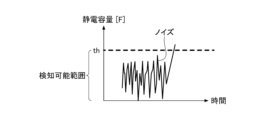
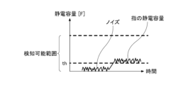
- FIG. 4 is a diagram showing a comparative example of capacitance detected by the grip detection device according to one embodiment
- FIG. 1 is a diagram showing an example of a circuit configuration provided in a grip detection device according to an embodiment
- FIG. 1 is a diagram showing an example of a circuit configuration provided in a grip detection device according to an embodiment
- FIG. 1 is a diagram showing an example of a circuit configuration provided in a grip detection device according to an embodiment
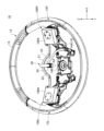
- FIG. 1 is a plan view of a steering device 10 according to one embodiment.
- FIG. 2 is an external perspective view of the steering device 10 according to one embodiment.
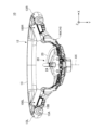
- FIG. 3 is a cross-sectional view of the steering device 10 according to one embodiment, taken along line AA in FIG.
- FIG. 4 is an exploded perspective view of the steering device 10 according to one embodiment.
- the X-axis direction is the horizontal direction
- the Y-axis direction is the front-rear direction
- the Z-axis direction is the vertical direction.
- the positive direction of the X-axis is the right direction
- the positive direction of the Y-axis is the forward direction
- the positive direction of the Z-axis is the upward direction.
- a steering device 10 shown in FIG. 1 is mounted in a vehicle interior of a vehicle such as an automobile, and is a device for performing steering wheel operation and various switch operations of the vehicle.
- the steering device 10 includes a steering wheel 12, a switch unit 100L, a switch unit 100R, and a connection section 20.
- the steering wheel 12 is configured with a rim portion 13 and spoke portions 14 .
- the rim portion 13 is an annular portion that is gripped by the fingers of the operator's hand and used for steering operation.
- the cross-sectional configuration of the rim portion 13 includes a metallic rim core 13A arranged in the center and a resin (for example, urethane) covering the outer surface of the rim core 13A. and a covering portion 13B.
- a region on the left side (X-axis negative side) of the rim portion 13 serves as a grip portion 13L that is gripped by fingers of the operator's left hand.
- a region on the right side (X-axis positive side) of the rim portion 13 serves as a grasping portion 13R that is grasped by the fingers of the operator's right hand.
- the spoke portion 14 has a spoke core metal portion 14A.
- the spoke core metal portion 14A is a metal portion provided inside the steering wheel 12 so as to extend in the left-right direction (X-axis direction).
- the left (X-axis negative side) end of the spoke core metal portion 14A is connected to the rim core metal portion 13A in the region of the grip portion 13L of the rim portion 13, and the right (X-axis positive side) end thereof is connected to the rim.
- the grip portion 13R of the portion 13 is connected to the rim cored bar portion 13A. Thereby, the spoke core metal portion 14A supports the rim portion 13 from the inside.
- the spoke core bar portion 14A has a shape in which the central portion is recessed toward the back side (positive side of the Y axis), and the through hole 14B provided in the central portion (on the central axis AX) has the It is fixed by a nut (not shown) or the like to a steering shaft (not shown) inserted through the through hole 14B.
- the spoke core metal portion 14A rotates together with the steering wheel 12 as the steering wheel is operated, and the steering shaft can be rotated around the central axis AX.
- the spoke core metal portion 14A is formed integrally with the rim core metal portion 13A of the rim portion 13 using a metal material. Further, as shown in FIG.
- an installation surface 14C facing the operator side (Y-axis negative side) on which the switch unit 100L is installed is formed at the left end portion of the spoke core portion 14A.
- a right end portion of the spoke core portion 14A is formed with an installation surface 14D that faces the operator (negative Y-axis side) and on which the switch unit 100R is installed.
- the spoke core metal portion 14A is actually covered with a functional component such as a resin cover or horn.
- the switch units 100L and 100R are installed on the spoke core metal portion 14A to perform various switch operations.
- the switch unit 100L is installed on the installation surface 14C at the left end of the spoke core 14A.
- the switch unit 100R is installed on the installation surface 14D at the right end of the spoke core 14A.
- the switch units 100L and 100R have a substantially rectangular shape when viewed from the Y-axis negative side, and have bilaterally symmetrical shapes with respect to a plane passing through the central axis AX.
- the surface of each of the switch units 100L and 100R on the operator side serves as an operation surface 100A on which various switch operations are performed.
- the switch units 100L and 100R are bilaterally symmetrical rectangles, both of which are provided with swinging type operation knobs 104, and are capable of pressing and inputting in four directions. It is also possible to combine arbitrary input means such as a push switch and a toggle switch as the input means.
- the switch unit 100L is provided in the vicinity of the grip portion 13L of the rim portion 13, and can detect the left hand finger of the operator gripping the region of the grip portion 13L in a non-contact manner.
- the switch unit 100R is provided in the vicinity of the grip portion 13R of the rim portion 13, and can detect the finger of the right hand of the operator gripping the area of the grip portion 13R in a non-contact manner.
- the connecting portion 20 is provided for electrically connecting the switch units 100L, 100R and the spoke core metal portion 14A to the control device 150 (see FIG. 7).
- the connecting portion 20 has a first cable 21 , a second cable 22 , a third cable 23 and a connector 24 .
- the first cable 21 connects between the terminal (not shown) of the switch unit 100R and the connector 24 .
- the second cable 22 connects between the terminal (not shown) of the switch unit 100L and the connector 24 .
- the third cable 23 has one end fixed to the spoke core metal portion 14A by a method such as screwing, and connects between the spoke core metal portion 14A and the connector 24 .
- Connector 24 connects first cable 21 , second cable 22 , and third cable 23 together to control device 150 by being connected to control device 150 .
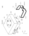
- FIG. 5 is an external perspective view of a switch unit 100R according to one embodiment.
- FIG. 6 is an exploded perspective view of the switch unit 100R according to one embodiment.
- the switch unit 100R includes a case 102, an operation knob 104, and an electrostatic sensor section 110.
- the case 102 is a resin container-shaped member having a hollow structure. Case 102 has a substantially rectangular parallelepiped shape. A surface 102A of the case 102 facing the user serves as an operation surface 100A on which various switch operations are performed. An operation knob 104 for switch operation is provided on the surface 102A. Inside the case 102, there are provided a circuit board, a switch element mounted on the circuit board, an actuator for pressing the switch element according to the operation of the operation knob 104, and the like (not shown).
- the case 102 is configured by combining an upper case 102B and a lower case 102C. Both the upper case 102B and the lower case 102C have a rectangular parallelepiped shape that is thin in the Y-axis direction. However, in a plan view from the operator side (Y-axis negative side), the lower case 102C has a rectangular shape that is one size smaller than the upper case 102B.
- the electrostatic sensor unit 110 is a sheet-like sensor provided for non-contact detection of gripping of the gripping portion 13R on the right side of the rim portion 13 by the operator's fingers by an electrostatic method that detects the capacitance of the fingers. sensor.
- the electrostatic sensor section 110 includes a flexible substrate 112, and a first detection electrode 114-1 and a second detection electrode 114-2 provided on the flexible substrate 112. As shown in FIG.
- the flexible substrate 112 is a sheet-like member made of resin that is bendable and has insulating properties.
- the flexible board 112 has a shape along the three side surfaces of the lower case 102C by being bent at two points at right angles.
- the flexible substrate 112 has a first plane portion 112A, a second plane portion 112B, and a third plane portion 112C. That is, the flexible board 112 is bent substantially at a right angle at the boundary between the first plane portion 112A and the second plane portion 112B and the boundary between the second plane portion 112B and the third plane portion 112C.
- the first flat portion 112A is arranged to overlap from approximately the middle position of the side surface 102Ca on the upper side (positive side of the Z axis) of the lower case 102C to the first corner portion C1.
- the second plane portion 112B is arranged to overlap from the first corner portion C1 to the second corner portion C2 of the right side (X-axis positive side) side surface 102Cb of the lower case 102C.
- the third plane portion 112C is arranged to overlap from approximately the middle position of the side surface 102Cc on the lower side (negative Z-axis side) of the lower case 102C to the second corner portion C2.
- the first detection electrode 114-1 is bent at a right angle along the first plane portion 112A and the second plane portion 112B from the first plane portion 112A of the flexible substrate 112 to the intermediate position of the second plane portion 112B. placed. That is, the first detection electrode 114-1 is connected to the upper (positive side of the Z-axis) and the right (positive side of the X-axis) first corner C1 (of the pair of corners facing the rim) of the lower case 102C. (an example of "one corner" of the first corner C1) and arranged by being bent at a right angle along the first corner C1.
- the first detection electrode 114-1 hovers over the capacitance of the finger of the operator's right hand, which is present close to the upper side (positive direction of the Z-axis) and the right side (positive direction of the X-axis) of the case 102. detectable. That is, the first detection electrode 114-1 can detect the fingers of the operator gripping the upper (Z-axis positive side) region (the region closer to one corner) of the grip portion 13R.
- the second detection electrode 114-2 is bent at right angles along the third plane portion 112C and the second plane portion 112B from the third plane portion 112C of the flexible substrate 112 to the intermediate position of the second plane portion 112B. placed. That is, the second detection electrode 114-2 is connected to a second corner portion C2 (“a pair of corner portions facing the rim portion) on the lower side (negative side of the Z axis) and the right side (positive side of the X axis) of the lower case 102C. (an example of "the other corner”), and is arranged by being bent at a right angle along the second corner C2.
- the second detection electrode 114-2 hovers the capacitance of the finger of the operator's right hand, which is present close to the lower side (negative direction of the Z-axis) and the right side (positive direction of the X-axis) of the case 102. detectable. That is, the second detection electrode 114-2 can detect the fingers of the operator gripping the lower (Z-axis negative side) region (the region closer to the other corner) of the grip portion 13R. .
- the detection electrodes 114-1 and 114-2 are provided integrally with the switch unit 100R provided on the spoke portion 14 of the steering wheel 12 in the vicinity of the connection area between the rim portion 13 and the spoke portion 14 of the steering wheel 12.
- the detection electrodes 114-1 and 114-2 for example, ITO (Indium Tin Oxide), IZO (Indium Zinc Oxide), a metal film (for example, silver, copper, a composite material of aluminum and molybdenum), etc.
- a conductor is used.
- the electrostatic sensor unit 110 is adhered to the three side surfaces of the lower case 102C by arbitrary adhesion means (for example, double-sided tape, etc.) on the surface of the flexible substrate 112 facing the lower case 102C.
- arbitrary adhesion means for example, double-sided tape, etc.
- the configuration of the switch unit 100R has been described above, but the configuration of the switch unit 100L is substantially symmetrical with the configuration of the switch unit 100R, and is basically the same configuration as the configuration of the switch unit 100R.
- the first detection electrode 114-1 is located on the upper side (positive side of the Z axis) and the left side (negative side of the X axis) of the lower case 102C. (an example of "one of the corners"), and is arranged by being bent substantially at a right angle along the first corner C1.
- the first detection electrode 114-1 detects the fingers of the operator's left hand, which are present close to the upper side (positive direction of the Z-axis) and the left side (negative direction of the X-axis) of the case 102.
- the second detection electrode 114-2 is positioned at the lower side (Z-axis negative side) and the left side (X-axis negative side) of the lower case 102C at a second corner C2 ("facing the rim portion"). (an example of "the other corner of the pair of corners") is arranged by being bent at a right angle along the second corner C2.
- the second detection electrode 114-2 detects the finger of the left hand of the operator present close to the lower side (Z-axis negative direction) and the left side (X-axis negative direction) of the case 102.
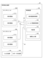
- FIG. 7 is a diagram showing the functional configuration of the control device 150 included in the grip detection device 30 according to one embodiment.
- the grip detection device 30 detects the presence or absence of fingers of the operator's hand gripping the rim portion 13 (grip portions 13L and 13R) of the steering wheel 12 based on the hover detection result by the electrostatic sensor portion 110. It is a device capable of making judgments and outputting the judgment results.
- the grip detection device 30 includes a control device 150 and detection electrodes 114-1 and 114-2 of the switch units 100L and 100R.
- the control device 150 is electrically connected to each of the detection electrodes 114-1 and 114-2 of the switch unit 100R via the first cable 21 and the connector 24.
- control device 150 is electrically connected to each of the detection electrodes 114-1 and 114-2 of the switch unit 100L via the second cable 22 and the connector 24.
- control device 150 is electrically connected to the rim cored bar 13A, the spoke cored bar 14A, the third cable 23, and the connector 24.
- the control device 150 includes a detection electrode control section 151, a shield electrode control section 152, a determination section 153, and a result output section 154.
- the detection electrode control unit 151 detects changes in capacitance in the detection electrodes 114-1 and 114-2. Specifically, the detection electrode control unit 151 drives the detection electrodes 114-1 and 114-2 by applying a sinusoidal AC voltage as a drive signal to the detection electrodes 114-1 and 114-2. do. The detection electrodes 114-1 and 114-2 detect changes in current values of currents flowing through the detection electrodes 114-1 and 114-2 as changes in capacitance.
- Detecting electrodes 114-1 and 114-2 included in the switch unit 100R are provided in the vicinity of the gripping portion 13R so as to face the gripping portion 13R. Therefore, when the fingers of the operator's right hand grip the grip portion 13R, the fingers of the operator's right hand are present close to the detection electrodes 114-1 and 114-2 of the switch unit 100R. As a result, the detection electrodes 114-1 and 114-2 of the switch unit 100R are capacitively coupled with the fingers of the operator's right hand, and the current values of the currents flowing through the detection electrodes 114-1 and 114-2 change. .
- the detection electrodes 114-1 and 114-2 of the switch unit 100R can perform hover detection (non-contact detection) of the finger of the operator's right hand.
- the detection electrodes 114-1 and 114-2 of the switch unit 100R have a shape that is bent at a substantially right angle. It is possible to detect the operator's right hand hover over a range of approximately ⁇ 30° on the grip portion 13R.
- detection electrodes 114-1 and 114-2 included in the switch unit 100L are provided in the vicinity of the gripping portion 13L so as to face the gripping portion 13L. Therefore, when the fingers of the operator's left hand grasp the grip portion 13L, the fingers of the operator's left hand are present close to the detection electrodes 114-1 and 114-2 of the switch unit 100L. As a result, the detection electrodes 114-1 and 114-2 of the switch unit 100L are capacitively coupled with the fingers of the operator's left hand, and the current values of the currents flowing through the detection electrodes 114-1 and 114-2 change. .
- the detection electrodes 114-1 and 114-2 of the switch unit 100L can perform hover detection (non-contact detection) of the finger of the left hand of the operator.
- the detection electrodes 114-1 and 114-2 of the switch unit 100L have a shape that is bent at a substantially right angle. It is possible to detect the operator's left hand hovering over a range of approximately ⁇ 30° on the grip portion 13L.
- the shield electrode control unit 152 generates an active shield signal and outputs the active shield signal to the rim cored bar 13A via the connector 24, the third cable 23, and the spoke cored bar 14A. As a result, the shield electrode controller 152 drives the rim core metal portion 13A as an active shield electrode.
- the active shield signal is, for example, a signal having a waveform synchronized with the driving signal applied to the sensing electrodes 114-1 and 114-2 from the sensing electrode control section 151 (that is, an AC voltage consisting of a sine wave).
- the rim core metal portion 13A is driven as an active shield electrode, there is no increase in the capacitance value due to the existence of the rim core metal portion 13A, and the detection electrode 114- The noise component added to 1,114-2 can be removed. That is, it is possible to remove the increase in capacitance and the noise component due to the rim core metal portion 13A from the capacitance detected by the detection electrodes 114-1 and 114-2 (see FIG. 8, which will be described later).
- the determination unit 153 determines whether or not there are fingers of the operator gripping the gripping portions 13L and 13R based on changes in the capacitance of the sensing electrodes 114-1 and 114-2 detected by the sensing electrode control portion 151. .
- the determination unit 153 determines whether the right hand of the operator who grips the grip portion 13R. Assume it has fingers. Since the spoke portion 14 is present, there are cases where the finger is present only above (positive direction of the Z-axis) or below (negative direction of the Z-axis) the grip portion 13R. If the measured value or variation of at least one of the electrodes -1 and 114-2 exceeds a predetermined threshold value, it may be determined that the finger of the operator's right hand is present.
- the determination unit 153 determines whether the right hand of the operator who grips the grip portion 13R. Assume there are no fingers.
- the determination unit 153 determines whether the operator holding the holding unit 13L Assume there are fingers on the left hand.
- the determination unit 153 determines whether the left hand of the operator who grips the grip portion 13L Assume there are no fingers.
- the threshold th a suitable value obtained in advance by actual machine tests, simulations, etc. is used.
- the capacitance detected by detection electrodes 114-1 and 114-2 is the capacitance of rim core metal portion 13A.
- noise components from the rim cored bar portion 13A are removed.
- the threshold value th a value obtained by removing the capacitance of the rim core metal portion 13A and the noise component from the rim core metal portion 13A by the active shield electrode is used as the threshold value th. The value is low compared to the conventional configuration that does not use it.
- the result output unit 154 transmits the determination result by the determination unit 153 (that is, the presence or absence of fingers of the operator gripping the grip units 13L and 13R) to an external device (for example, a device that executes processing according to the determination result by the determination unit 153).
- an external device for example, a device that executes processing according to the determination result by the determination unit 153.
- control processing in the control device 150 includes, for example, a processor (eg, CPU), a storage medium (eg, ROM (Read Only Memory), RAM (Random Access Memory), SSD (Solid State Drive), etc.), an external interface, etc. is implemented by a computer (for example, an IC (Integrated Circuit)).
- a processor eg, CPU
- storage medium eg, ROM (Read Only Memory), RAM (Random Access Memory), SSD (Solid State Drive), etc.
- an external interface etc.
- FIG. 8A and 8B are diagrams showing comparative examples of capacitance detected by the grip detection device 30 according to one embodiment.
- FIG. 8A is a diagram showing an example of capacitance detected by a conventional grasp detection device that does not have an active shield electrode.
- FIG. 8B is a diagram showing an example of capacitance detected by the grip detection device 30 according to one embodiment.
- the capacitance due to the rim core metal part and the noise component from the rim core metal part are added to the detection electrode.
- the detected capacitance includes the capacitance and noise component due to the rim cored bar.
- the sensor has a detectable range in which the output value does not change and saturates even if a capacitance exceeding a predetermined value is applied. Even if a threshold value th for determining that a finger is approaching is set near the detectable range, a small amount of electrostatic Since even an increase in capacity easily exceeds the threshold th, the conventional grasp detection device cannot detect the finger of the operator grasping the rim portion of the steering wheel with high accuracy. In other words, it is difficult to improve the accuracy because the capacitance component accompanying the approach of the finger is smaller than the unnecessary capacitance component (capacitance due to the rim core metal portion and noise component from the rim core metal portion). .
- the grip detection device 30 drives the rim core metal portion 13A as an active shield electrode, thereby reducing the capacitance of the rim core metal portion 13A and the rim core metal portion 13A. Noise components added to the detection electrodes 114-1 and 114-2 from the portion 13A can be removed. In other words, the grip detection device 30 according to one embodiment removes noise components from the capacitance detected by the detection electrodes 114-1 and 114-2, and detects only the capacitance of the operator's fingers. be able to.
- the grip detection device 30 can lower the threshold th for finger detection determination, and the margin between the threshold th for finger detection determination and the detectable range of the sensor allows steering wheel movement to be reduced.
- the finger of the operator gripping the rim portion 13 of the wheel 12 can be detected with high accuracy. In other words, the accuracy is enhanced because the capacitance component accompanying the approach of the finger is greater than the unnecessary capacitance component (the capacitance due to the rim core metal portion 13A and the noise component from the rim core metal portion 13A). becomes easier.
- FIG. 9 to 11 are diagrams showing an example of the circuit configuration 30A included in the grip detection device 30 according to one embodiment.
- the circuit configuration 30A shown in FIGS. 9 to 11 includes the signal generation source 32 (shield electrode control section 152), the voltage follower circuit 155, the detection electrode 114, the core metal 12A of the steering wheel 12 (that is, the rim core metal section 13A and the spokes).
- a core metal portion 14A) is provided.
- the active shield signal generated by the signal generation source 32 is supplied to the metal core 12A via the voltage follower circuit 155.
- the voltage follower circuit 155 is controlled by the shield electrode control unit 152 when connecting the control device 150 (shield electrode control unit 152), which is a signal source with high output impedance, to the shield electrode (metal core 12A), which is a load with low impedance.
- the generated active shield signal has a sufficient voltage and is output to the metal core 12A. That is, by having the voltage follower circuit 155, the metal core 12A can be stably driven as an active shield electrode. As a result, the circuit configuration 30A drives the core metal 12A as an active shield electrode by an active shield signal having a stable voltage, and the capacitance detected by the detection electrode 114 is calculated from the capacitance of the core metal 12A and , the noise component from the cored bar 12A is removed.
- circuit configuration 30A shown in FIG. 9 is grounded via the zener diode 35 between the voltage follower circuit 155 and the spoke core metal portion 14A.
- the space between the voltage follower circuit 155 and the spoke core metal portion 14A is grounded through the varistor .
- the voltage follower circuit 155 and the spoke core metal portion 14A are grounded via a clamp diode configuration 37 composed of diodes 37A and 37B.
- the grip detection device 30 can be driven as an active shield electrode while the rim core metal portion 13A is grounded. Electrostatic discharge) countermeasures can be played.
- the grip detection device 30 includes the electrostatic sensor unit 110 provided on the spoke portion 14 of the steering wheel 12 and having the detection electrode 114 facing the rim portion 13 of the steering wheel 12; A controller 150 that controls the electrostatic sensor unit 110, and a determination unit 153 that determines whether or not there is a finger gripping the rim unit 13 based on the hover detection result of the electrostatic sensor unit 110.
- the controller 150 includes: The metal core of the steering wheel 12 is used as the shield electrode of the electrostatic sensor section 110 .
- the grip detection device 30 according to the embodiment can provide the shield electrode without providing a separate member, so that the influence of noise on the hover detection by the electrostatic sensor unit 110 can be suppressed with an inexpensive configuration. can be done. Therefore, according to the grip detection device 30 according to one embodiment, it is possible to detect the finger of the operator gripping the rim portion 13 of the steering wheel 12 with high accuracy.
- control device 150 drives the metal core of the steering wheel 12 as an active shield electrode.
- the grip detection device 30 can improve the hover detection performance of the electrostatic sensor unit 110 .
- the core metal of the steering wheel 12 includes a rim core metal portion 13A provided at the center of the rim portion 13 and spoke core metal portions 14A forming the spoke portions 14.
- the control device 150 is connected to the spoke core metal portion 14A and drives the rim core metal portion 13A as an active shield electrode via the spoke core metal portion 14A.
- the grip detection device 30 can connect the control device 150 to the spoke core metal portion 14A, so that the control device 150 can be easily connected to the core metal of the steering wheel 12.
- control device 150 drives the active shield electrode with a drive signal having a waveform synchronized with the drive signal of the detection electrode 114 .
- the grip detection device 30 can remove noise components from the active shield electrode to the electrostatic sensor unit 110, and therefore can improve the hover detection performance of the electrostatic sensor unit 110. can.
- the detection electrodes 114 are provided near the connection area between the rim portion 13 and the spoke portions 14 .
- the grip detection device 30 can perform hover detection of the operator's finger gripping the rim portion 13 near the connection area of the spoke portions 14 with high accuracy using the detection electrodes 114 .
- the detection electrode 114 is provided integrally with the switch unit 100 provided on the spoke portion 14 of the steering wheel 12 .
- the grip detection device 30 can install the detection electrodes 114 with good space efficiency, and the detection electrodes 114 can perform hover detection of the operator's fingers gripping the rim portion 13 with high accuracy. be able to.
- the switch unit 100 has a pair of corners C1 and C2 at positions facing the rim portion 13, and the electrostatic sensor section 110 has a pair of corners C1 and C2.
- the first detection electrode 114-1 is bent along the first corner C1 of C2, and the second detection electrode 114-1 is bent along the second corner C2 of the pair of corners. and a second sensing electrode 114-2.
- the grip detection device 30 can detect the finger gripping the area of the rim portion 13 closer to the first corner C1 and the area of the rim portion 13 closer to the second corner C2. It is possible to detect the hover individually and with high precision.
- the rim core metal portion 13A is driven as a so-called active shield electrode, in which a signal synchronized in phase with the driving signal applied to the detection electrode is applied to the rim core metal portion 13A.
- a so-called passive shield electrode, in which 13A is set to a constant voltage such as a ground voltage or a power supply voltage, may be used.
- the rim core metal portion 13A is driven as an active shield electrode via the spoke core metal portion 14A. It may be driven as an active shield electrode without passing through 14A.
Landscapes
- Engineering & Computer Science (AREA)
- Chemical & Material Sciences (AREA)
- Combustion & Propulsion (AREA)
- Transportation (AREA)
- Mechanical Engineering (AREA)
- Physics & Mathematics (AREA)
- General Physics & Mathematics (AREA)
- Switches That Are Operated By Magnetic Or Electric Fields (AREA)
Priority Applications (4)
| Application Number | Priority Date | Filing Date | Title |
|---|---|---|---|
| JP2023570766A JP7711882B2 (ja) | 2021-12-27 | 2022-12-05 | 把持検出装置およびステアリング装置 |
| DE112022006215.0T DE112022006215T5 (de) | 2021-12-27 | 2022-12-05 | Greiferfassungsvorrichtung und Lenkvorrichtung |
| CN202280071033.8A CN118159460A (zh) | 2021-12-27 | 2022-12-05 | 把持检测装置及转向装置 |
| US18/738,503 US20240328832A1 (en) | 2021-12-27 | 2024-06-10 | Gripping detection device and steering device |
Applications Claiming Priority (2)
| Application Number | Priority Date | Filing Date | Title |
|---|---|---|---|
| JP2021212504 | 2021-12-27 | ||
| JP2021-212504 | 2021-12-27 |
Related Child Applications (1)
| Application Number | Title | Priority Date | Filing Date |
|---|---|---|---|
| US18/738,503 Continuation US20240328832A1 (en) | 2021-12-27 | 2024-06-10 | Gripping detection device and steering device |
Publications (1)
| Publication Number | Publication Date |
|---|---|
| WO2023127415A1 true WO2023127415A1 (ja) | 2023-07-06 |
Family
ID=86998576
Family Applications (1)
| Application Number | Title | Priority Date | Filing Date |
|---|---|---|---|
| PCT/JP2022/044763 Ceased WO2023127415A1 (ja) | 2021-12-27 | 2022-12-05 | 把持検出装置およびステアリング装置 |
Country Status (5)
| Country | Link |
|---|---|
| US (1) | US20240328832A1 (https=) |
| JP (1) | JP7711882B2 (https=) |
| CN (1) | CN118159460A (https=) |
| DE (1) | DE112022006215T5 (https=) |
| WO (1) | WO2023127415A1 (https=) |
Cited By (1)
| Publication number | Priority date | Publication date | Assignee | Title |
|---|---|---|---|---|
| WO2025046945A1 (ja) * | 2023-08-31 | 2025-03-06 | アルプスアルパイン株式会社 | センサ装置 |
Families Citing this family (2)
| Publication number | Priority date | Publication date | Assignee | Title |
|---|---|---|---|---|
| CN118574762A (zh) * | 2022-01-17 | 2024-08-30 | 本田技研工业株式会社 | 转向装置 |
| CN118701073A (zh) * | 2023-03-27 | 2024-09-27 | 本田技研工业株式会社 | 把持判定系统 |
Citations (6)
| Publication number | Priority date | Publication date | Assignee | Title |
|---|---|---|---|---|
| JP2016016697A (ja) * | 2014-07-04 | 2016-02-01 | 本田技研工業株式会社 | 車両用表示装置 |
| KR20190083777A (ko) * | 2018-01-05 | 2019-07-15 | 현대자동차주식회사 | 스티어링 휠 |
| WO2019202977A1 (ja) * | 2018-04-20 | 2019-10-24 | パナソニックIpマネジメント株式会社 | 静電検出装置 |
| WO2020195620A1 (ja) * | 2019-03-25 | 2020-10-01 | アルプスアルパイン株式会社 | センサ装置及びステアリングホイール |
| WO2022209426A1 (ja) * | 2021-03-29 | 2022-10-06 | オートリブ ディベロップメント エービー | 把持判定システム及び把持判定方法 |
| JP2022148332A (ja) * | 2021-03-24 | 2022-10-06 | 本田技研工業株式会社 | 車両のステアリング装置 |
Family Cites Families (2)
| Publication number | Priority date | Publication date | Assignee | Title |
|---|---|---|---|---|
| JP7210378B2 (ja) * | 2019-05-29 | 2023-01-23 | 株式会社豊田中央研究所 | グリップ |
| DE102021110300B4 (de) * | 2021-04-22 | 2025-11-13 | Preh Gmbh | Anordnung aus einem eine Elektrode aufweisenden Lenkrad und einer vor elektrodenseitig eingekoppelter Überspannung besser geschützten Auswertelektronik zur kapazitiven Berührerkennung sowie zugehöriges Kraftfahrzeug |
-
2022
- 2022-12-05 JP JP2023570766A patent/JP7711882B2/ja active Active
- 2022-12-05 WO PCT/JP2022/044763 patent/WO2023127415A1/ja not_active Ceased
- 2022-12-05 DE DE112022006215.0T patent/DE112022006215T5/de active Pending
- 2022-12-05 CN CN202280071033.8A patent/CN118159460A/zh active Pending
-
2024
- 2024-06-10 US US18/738,503 patent/US20240328832A1/en active Pending
Patent Citations (6)
| Publication number | Priority date | Publication date | Assignee | Title |
|---|---|---|---|---|
| JP2016016697A (ja) * | 2014-07-04 | 2016-02-01 | 本田技研工業株式会社 | 車両用表示装置 |
| KR20190083777A (ko) * | 2018-01-05 | 2019-07-15 | 현대자동차주식회사 | 스티어링 휠 |
| WO2019202977A1 (ja) * | 2018-04-20 | 2019-10-24 | パナソニックIpマネジメント株式会社 | 静電検出装置 |
| WO2020195620A1 (ja) * | 2019-03-25 | 2020-10-01 | アルプスアルパイン株式会社 | センサ装置及びステアリングホイール |
| JP2022148332A (ja) * | 2021-03-24 | 2022-10-06 | 本田技研工業株式会社 | 車両のステアリング装置 |
| WO2022209426A1 (ja) * | 2021-03-29 | 2022-10-06 | オートリブ ディベロップメント エービー | 把持判定システム及び把持判定方法 |
Cited By (1)
| Publication number | Priority date | Publication date | Assignee | Title |
|---|---|---|---|---|
| WO2025046945A1 (ja) * | 2023-08-31 | 2025-03-06 | アルプスアルパイン株式会社 | センサ装置 |
Also Published As
| Publication number | Publication date |
|---|---|
| JPWO2023127415A1 (https=) | 2023-07-06 |
| CN118159460A (zh) | 2024-06-07 |
| JP7711882B2 (ja) | 2025-07-23 |
| DE112022006215T5 (de) | 2024-12-19 |
| US20240328832A1 (en) | 2024-10-03 |
Similar Documents
| Publication | Publication Date | Title |
|---|---|---|
| WO2023127415A1 (ja) | 把持検出装置およびステアリング装置 | |
| JP6165481B2 (ja) | 把持状態検出センサ | |
| JP7577915B2 (ja) | センサ装置 | |
| US8148652B2 (en) | Position detecting device and position detecting method | |
| WO2018173439A1 (ja) | センサ装置 | |
| JP7447376B2 (ja) | 操作検出装置 | |
| JP2009301300A (ja) | 入力装置 | |
| US20210255739A1 (en) | Input device | |
| JP2018185273A (ja) | ロボット | |
| JP2015229399A (ja) | 把持検出装置及びしきい値設定システム | |
| JP2011007654A (ja) | 接触検出装置及びロボット | |
| JP2013130530A (ja) | 滑り及び滑り方向検出装置 | |
| JP2021165642A (ja) | 検出装置 | |
| JP5490043B2 (ja) | 乗員検知装置 | |
| JP5237330B2 (ja) | センサシートおよび入力装置 | |
| CN101593064A (zh) | 触控装置 | |
| CN116745877A (zh) | 静电电容传感器 | |
| WO2017122702A1 (ja) | 操作装置 | |
| US20250341902A1 (en) | Rotary input device | |
| CN102103450B (zh) | 电阻式触控面板 | |
| KR102241975B1 (ko) | 스티어링 휠 | |
| JP7426416B2 (ja) | 入力装置 | |
| JP2011224735A (ja) | ロボットハンド | |
| WO2025141858A1 (ja) | ステアリング装置および検出ユニット | |
| JP2014146138A (ja) | タッチパネル |
Legal Events
| Date | Code | Title | Description |
|---|---|---|---|
| 121 | Ep: the epo has been informed by wipo that ep was designated in this application |
Ref document number: 22915646 Country of ref document: EP Kind code of ref document: A1 |
|
| WWE | Wipo information: entry into national phase |
Ref document number: 2023570766 Country of ref document: JP |
|
| WWE | Wipo information: entry into national phase |
Ref document number: 202280071033.8 Country of ref document: CN |
|
| WWE | Wipo information: entry into national phase |
Ref document number: 112022006215 Country of ref document: DE |
|
| 122 | Ep: pct application non-entry in european phase |
Ref document number: 22915646 Country of ref document: EP Kind code of ref document: A1 |