WO2023120687A1 - 二次電池 - Google Patents
二次電池 Download PDFInfo
- Publication number
- WO2023120687A1 WO2023120687A1 PCT/JP2022/047544 JP2022047544W WO2023120687A1 WO 2023120687 A1 WO2023120687 A1 WO 2023120687A1 JP 2022047544 W JP2022047544 W JP 2022047544W WO 2023120687 A1 WO2023120687 A1 WO 2023120687A1
- Authority
- WO
- WIPO (PCT)
- Prior art keywords
- secondary battery
- negative electrode
- heat
- positive electrode
- group
- Prior art date
- Legal status (The legal status is an assumption and is not a legal conclusion. Google has not performed a legal analysis and makes no representation as to the accuracy of the status listed.)
- Ceased
Links
Images






Classifications
-
- H—ELECTRICITY
- H01—ELECTRIC ELEMENTS
- H01M—PROCESSES OR MEANS, e.g. BATTERIES, FOR THE DIRECT CONVERSION OF CHEMICAL ENERGY INTO ELECTRICAL ENERGY
- H01M10/00—Secondary cells; Manufacture thereof
- H01M10/05—Accumulators with non-aqueous electrolyte
- H01M10/052—Li-accumulators
- H01M10/0525—Rocking-chair batteries, i.e. batteries with lithium insertion or intercalation in both electrodes; Lithium-ion batteries
-
- H—ELECTRICITY
- H01—ELECTRIC ELEMENTS
- H01M—PROCESSES OR MEANS, e.g. BATTERIES, FOR THE DIRECT CONVERSION OF CHEMICAL ENERGY INTO ELECTRICAL ENERGY
- H01M10/00—Secondary cells; Manufacture thereof
- H01M10/05—Accumulators with non-aqueous electrolyte
- H01M10/052—Li-accumulators
-
- H—ELECTRICITY
- H01—ELECTRIC ELEMENTS
- H01M—PROCESSES OR MEANS, e.g. BATTERIES, FOR THE DIRECT CONVERSION OF CHEMICAL ENERGY INTO ELECTRICAL ENERGY
- H01M10/00—Secondary cells; Manufacture thereof
- H01M10/05—Accumulators with non-aqueous electrolyte
- H01M10/056—Accumulators with non-aqueous electrolyte characterised by the materials used as electrolytes, e.g. mixed inorganic/organic electrolytes
- H01M10/0564—Accumulators with non-aqueous electrolyte characterised by the materials used as electrolytes, e.g. mixed inorganic/organic electrolytes the electrolyte being constituted of organic materials only
- H01M10/0566—Liquid materials
- H01M10/0567—Liquid materials characterised by the additives
-
- H—ELECTRICITY
- H01—ELECTRIC ELEMENTS
- H01M—PROCESSES OR MEANS, e.g. BATTERIES, FOR THE DIRECT CONVERSION OF CHEMICAL ENERGY INTO ELECTRICAL ENERGY
- H01M10/00—Secondary cells; Manufacture thereof
- H01M10/05—Accumulators with non-aqueous electrolyte
- H01M10/056—Accumulators with non-aqueous electrolyte characterised by the materials used as electrolytes, e.g. mixed inorganic/organic electrolytes
- H01M10/0564—Accumulators with non-aqueous electrolyte characterised by the materials used as electrolytes, e.g. mixed inorganic/organic electrolytes the electrolyte being constituted of organic materials only
- H01M10/0566—Liquid materials
- H01M10/0568—Liquid materials characterised by the solutes
-
- H—ELECTRICITY
- H01—ELECTRIC ELEMENTS
- H01M—PROCESSES OR MEANS, e.g. BATTERIES, FOR THE DIRECT CONVERSION OF CHEMICAL ENERGY INTO ELECTRICAL ENERGY
- H01M10/00—Secondary cells; Manufacture thereof
- H01M10/05—Accumulators with non-aqueous electrolyte
- H01M10/056—Accumulators with non-aqueous electrolyte characterised by the materials used as electrolytes, e.g. mixed inorganic/organic electrolytes
- H01M10/0564—Accumulators with non-aqueous electrolyte characterised by the materials used as electrolytes, e.g. mixed inorganic/organic electrolytes the electrolyte being constituted of organic materials only
- H01M10/0566—Liquid materials
- H01M10/0569—Liquid materials characterised by the solvents
-
- H—ELECTRICITY
- H01—ELECTRIC ELEMENTS
- H01M—PROCESSES OR MEANS, e.g. BATTERIES, FOR THE DIRECT CONVERSION OF CHEMICAL ENERGY INTO ELECTRICAL ENERGY
- H01M50/00—Constructional details or processes of manufacture of the non-active parts of electrochemical cells other than fuel cells, e.g. hybrid cells
- H01M50/40—Separators; Membranes; Diaphragms; Spacing elements inside cells
- H01M50/409—Separators, membranes or diaphragms characterised by the material
-
- H—ELECTRICITY
- H01—ELECTRIC ELEMENTS
- H01M—PROCESSES OR MEANS, e.g. BATTERIES, FOR THE DIRECT CONVERSION OF CHEMICAL ENERGY INTO ELECTRICAL ENERGY
- H01M50/00—Constructional details or processes of manufacture of the non-active parts of electrochemical cells other than fuel cells, e.g. hybrid cells
- H01M50/40—Separators; Membranes; Diaphragms; Spacing elements inside cells
- H01M50/409—Separators, membranes or diaphragms characterised by the material
- H01M50/411—Organic material
- H01M50/414—Synthetic resins, e.g. thermoplastics or thermosetting resins
-
- H—ELECTRICITY
- H01—ELECTRIC ELEMENTS
- H01M—PROCESSES OR MEANS, e.g. BATTERIES, FOR THE DIRECT CONVERSION OF CHEMICAL ENERGY INTO ELECTRICAL ENERGY
- H01M50/00—Constructional details or processes of manufacture of the non-active parts of electrochemical cells other than fuel cells, e.g. hybrid cells
- H01M50/40—Separators; Membranes; Diaphragms; Spacing elements inside cells
- H01M50/409—Separators, membranes or diaphragms characterised by the material
- H01M50/411—Organic material
- H01M50/414—Synthetic resins, e.g. thermoplastics or thermosetting resins
- H01M50/42—Acrylic resins
-
- H—ELECTRICITY
- H01—ELECTRIC ELEMENTS
- H01M—PROCESSES OR MEANS, e.g. BATTERIES, FOR THE DIRECT CONVERSION OF CHEMICAL ENERGY INTO ELECTRICAL ENERGY
- H01M50/00—Constructional details or processes of manufacture of the non-active parts of electrochemical cells other than fuel cells, e.g. hybrid cells
- H01M50/40—Separators; Membranes; Diaphragms; Spacing elements inside cells
- H01M50/409—Separators, membranes or diaphragms characterised by the material
- H01M50/411—Organic material
- H01M50/414—Synthetic resins, e.g. thermoplastics or thermosetting resins
- H01M50/423—Polyamide resins
-
- H—ELECTRICITY
- H01—ELECTRIC ELEMENTS
- H01M—PROCESSES OR MEANS, e.g. BATTERIES, FOR THE DIRECT CONVERSION OF CHEMICAL ENERGY INTO ELECTRICAL ENERGY
- H01M50/00—Constructional details or processes of manufacture of the non-active parts of electrochemical cells other than fuel cells, e.g. hybrid cells
- H01M50/40—Separators; Membranes; Diaphragms; Spacing elements inside cells
- H01M50/409—Separators, membranes or diaphragms characterised by the material
- H01M50/411—Organic material
- H01M50/414—Synthetic resins, e.g. thermoplastics or thermosetting resins
- H01M50/426—Fluorocarbon polymers
-
- H—ELECTRICITY
- H01—ELECTRIC ELEMENTS
- H01M—PROCESSES OR MEANS, e.g. BATTERIES, FOR THE DIRECT CONVERSION OF CHEMICAL ENERGY INTO ELECTRICAL ENERGY
- H01M50/00—Constructional details or processes of manufacture of the non-active parts of electrochemical cells other than fuel cells, e.g. hybrid cells
- H01M50/40—Separators; Membranes; Diaphragms; Spacing elements inside cells
- H01M50/409—Separators, membranes or diaphragms characterised by the material
- H01M50/431—Inorganic material
- H01M50/434—Ceramics
-
- H—ELECTRICITY
- H01—ELECTRIC ELEMENTS
- H01M—PROCESSES OR MEANS, e.g. BATTERIES, FOR THE DIRECT CONVERSION OF CHEMICAL ENERGY INTO ELECTRICAL ENERGY
- H01M50/00—Constructional details or processes of manufacture of the non-active parts of electrochemical cells other than fuel cells, e.g. hybrid cells
- H01M50/40—Separators; Membranes; Diaphragms; Spacing elements inside cells
- H01M50/409—Separators, membranes or diaphragms characterised by the material
- H01M50/446—Composite material consisting of a mixture of organic and inorganic materials
-
- H—ELECTRICITY
- H01—ELECTRIC ELEMENTS
- H01M—PROCESSES OR MEANS, e.g. BATTERIES, FOR THE DIRECT CONVERSION OF CHEMICAL ENERGY INTO ELECTRICAL ENERGY
- H01M50/00—Constructional details or processes of manufacture of the non-active parts of electrochemical cells other than fuel cells, e.g. hybrid cells
- H01M50/40—Separators; Membranes; Diaphragms; Spacing elements inside cells
- H01M50/409—Separators, membranes or diaphragms characterised by the material
- H01M50/449—Separators, membranes or diaphragms characterised by the material having a layered structure
-
- H—ELECTRICITY
- H01—ELECTRIC ELEMENTS
- H01M—PROCESSES OR MEANS, e.g. BATTERIES, FOR THE DIRECT CONVERSION OF CHEMICAL ENERGY INTO ELECTRICAL ENERGY
- H01M50/00—Constructional details or processes of manufacture of the non-active parts of electrochemical cells other than fuel cells, e.g. hybrid cells
- H01M50/40—Separators; Membranes; Diaphragms; Spacing elements inside cells
- H01M50/409—Separators, membranes or diaphragms characterised by the material
- H01M50/449—Separators, membranes or diaphragms characterised by the material having a layered structure
- H01M50/451—Separators, membranes or diaphragms characterised by the material having a layered structure comprising layers of only organic material and layers containing inorganic material
-
- H—ELECTRICITY
- H01—ELECTRIC ELEMENTS
- H01M—PROCESSES OR MEANS, e.g. BATTERIES, FOR THE DIRECT CONVERSION OF CHEMICAL ENERGY INTO ELECTRICAL ENERGY
- H01M50/00—Constructional details or processes of manufacture of the non-active parts of electrochemical cells other than fuel cells, e.g. hybrid cells
- H01M50/40—Separators; Membranes; Diaphragms; Spacing elements inside cells
- H01M50/489—Separators, membranes, diaphragms or spacing elements inside the cells, characterised by their physical properties, e.g. swelling degree, hydrophilicity or shut down properties
-
- Y—GENERAL TAGGING OF NEW TECHNOLOGICAL DEVELOPMENTS; GENERAL TAGGING OF CROSS-SECTIONAL TECHNOLOGIES SPANNING OVER SEVERAL SECTIONS OF THE IPC; TECHNICAL SUBJECTS COVERED BY FORMER USPC CROSS-REFERENCE ART COLLECTIONS [XRACs] AND DIGESTS
- Y02—TECHNOLOGIES OR APPLICATIONS FOR MITIGATION OR ADAPTATION AGAINST CLIMATE CHANGE
- Y02E—REDUCTION OF GREENHOUSE GAS [GHG] EMISSIONS, RELATED TO ENERGY GENERATION, TRANSMISSION OR DISTRIBUTION
- Y02E60/00—Enabling technologies; Technologies with a potential or indirect contribution to GHG emissions mitigation
- Y02E60/10—Energy storage using batteries
Definitions
- This technology relates to secondary batteries.
- the secondary battery includes a positive electrode, a negative electrode, and an electrolytic solution, and various studies have been made on the configuration of the secondary battery.
- Faiz Ahmed et al. ⁇ Novel divalent organo-lithium salts with high electrochemical and thermal stability for aqueous rechargeable Li-Ion batteries'', Electrochimica Acta, 298, 2019, 709-716 Faiz Ahmed et al., ⁇ Highly conductive divalent fluorosulfonyl imide based electrolytes improving Li-ion battery performance: Additive potentiating'', Journal of Power Sources, 455, 2020, 227980
- a secondary battery that can obtain excellent battery characteristics is desired.
- a secondary battery includes a positive electrode including a positive electrode active material layer, a negative electrode including a negative electrode active material layer, a separator and a heat-resistant layer disposed between the positive electrode and the negative electrode, and an electrolyte salt. and an electrolytic solution comprising:
- the heat-resistant layer is arranged at least in a region where the positive electrode active material layer and the negative electrode active material layer face each other, and has a melting point or decomposition temperature higher than that of the separator.
- the electrolyte salt contains an imide anion, and the imide anion is a first imide anion represented by formula (1), a second imide anion represented by formula (2), and a third imide anion represented by formula (3). At least one of the imide anion and the quaternary imide anion represented by formula (4) is included.
- Each of R3 and R4 is either a fluorine group or a fluorinated alkyl group.
- Each of X1, X2, X3 and X4 is one of a carbonyl group, a sulfinyl group and a sulfonyl group.
- R5 is a fluorinated alkylene group.
- Each of Y1, Y2 and Y3 is a carbonyl group, a sulfinyl group and a sulfonyl group.
- R6 and R7 is either a fluorine group or a fluorinated alkyl group.
- R8 is any one of an alkylene group, a phenylene group, a fluorinated alkylene group and a fluorinated phenylene group.
- Z1 , Z2, Z3 and Z4 are each a carbonyl group, a sulfinyl group and a sulfonyl group.
- the separator and the heat-resistant layer are arranged between the positive electrode and the negative electrode, and in the heat-resistant layer, at least the positive electrode active material layer and the negative electrode active material layer face each other. region and has a melting point or decomposition temperature higher than that of the separator, and the electrolyte salt of the electrolytic solution has imide anions such as primary imide anion, secondary imide anion, tertiary imide anion and Since at least one of the quaternary imide anions is included, excellent battery characteristics can be obtained.
- FIG. 2 is a cross-sectional view showing the configuration of part of the battery element shown in FIG. 1.
- FIG. FIG. 2 is a cross-sectional view showing the overall configuration of the battery element shown in FIG. 1; 4 is a cross-sectional view showing the configuration of a battery element in Modification 1.
- FIG. FIG. 10 is a cross-sectional view showing the configuration of a battery element in Modification 2;
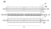
- FIG. 11 is a cross-sectional view showing the configuration of a battery element in Modification 3;
- FIG. 11 is a cross-sectional view showing the configuration of a battery element in modification 4;
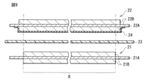
- FIG. 11 is a cross-sectional view showing the configuration of a battery element in modification 5;
- FIG. 11 is a cross-sectional view showing the configuration of a battery element in modification 6;
- FIG. 11 is a cross-sectional view showing the configuration of a battery element in modification 7;
- FIG. 11 is a cross-sectional view showing the configuration of a battery element in modification 8;
- FIG. 3 is a block diagram showing the configuration of an application example of a secondary battery;
- the secondary battery described here is a secondary battery in which battery capacity is obtained by utilizing the absorption and release of electrode reactants, and is equipped with an electrolyte along with a positive electrode and a negative electrode.
- the charge capacity of the negative electrode is larger than the discharge capacity of the positive electrode. That is, the electrochemical capacity per unit area of the negative electrode is set to be larger than the electrochemical capacity per unit area of the positive electrode. This is to prevent electrode reactants from depositing on the surface of the negative electrode during charging.
- the type of electrode reactant is not particularly limited, but specifically light metals such as alkali metals and alkaline earth metals.
- alkali metals are lithium, sodium and potassium, and examples of alkaline earth metals are beryllium, magnesium and calcium.
- the type of electrode reactant may be other light metals such as aluminum.
- lithium ion secondary battery A secondary battery whose battery capacity is obtained by utilizing the absorption and release of lithium is a so-called lithium ion secondary battery.
- lithium ion secondary battery lithium is intercalated and deintercalated in an ionic state.
- FIG. 1 shows a perspective configuration of a secondary battery.
- FIG. 2 shows a cross-sectional structure of part of the battery element 20 shown in FIG.
- FIG. 3 shows the overall cross-sectional structure of the battery element 20 shown in FIG.
- FIG. 1 shows a state in which the exterior film 10 and the battery element 20 are separated from each other, and the cross section of the battery element 20 along the XZ plane is indicated by a broken line.
- FIG. 3 shows a state in which the positive electrode 21, the negative electrode 22, the separator 23, and the heat-resistant layer 24 are separated from each other before winding.
- This secondary battery as shown in FIGS. 1 to 3, includes an exterior film 10, a battery element 20, a positive electrode lead 31, a negative electrode lead 32, and sealing films 41 and .
- the secondary battery described here is a laminated film type secondary battery using a flexible or pliable exterior film 10 .
- the upper side in each of FIGS. 1 to 3 is the upper side of the secondary battery
- the lower side in each of FIGS. 1 to 3 is the lower side of the secondary battery
- the exterior film 10 is an exterior member that houses the battery element 20, and has a sealed bag-like structure with the battery element 20 housed therein.
- the exterior film 10 accommodates the electrolytic solution together with the positive electrode 21 and the negative electrode 22 .
- the exterior film 10 is a single film-like member and is folded in the folding direction F.
- the exterior film 10 is provided with a recessed portion 10U (so-called deep drawn portion) for housing the battery element 20 .
- the exterior film 10 is a three-layer laminate film in which a fusion layer, a metal layer, and a surface protective layer are laminated in this order from the inside. Outer peripheral edge portions of the fusion layer are fused together.
- the fusible layer contains a polymer compound such as polypropylene.
- the metal layer contains a metal material such as aluminum.
- the surface protective layer contains a polymer compound such as nylon.
- the configuration (number of layers) of the exterior film 10 is not particularly limited, and may be one layer, two layers, or four layers or more.
- the sealing film 41 is inserted between the exterior film 10 and the positive electrode lead 31
- the sealing film 42 is inserted between the exterior film 10 and the negative electrode lead 32 .
- one or both of the sealing films 41 and 42 may be omitted.
- the sealing film 41 is a sealing member that prevents external air from entering the exterior film 10 . Further, the sealing film 41 contains a polymer compound such as polyolefin having adhesiveness to the positive electrode lead 31, and a specific example of the polymer compound is polypropylene.
- the structure of the sealing film 42 is the same as the structure of the sealing film 41 except that it is a sealing member having adhesion to the negative electrode lead 32 . That is, the sealing film 42 contains a polymer compound such as polyolefin that has adhesiveness to the negative electrode lead 32 .
- the battery element 20 is a power generation element including a positive electrode 21, a negative electrode 22, a separator 23, a heat-resistant layer 24, and an electrolytic solution (not shown), as shown in FIGS. 10 is housed inside.
- This battery element 20 is a so-called wound electrode assembly. That is, the positive electrode 21 and the negative electrode 22 are laminated with each other with the separator 23 and the heat-resistant layer 24 interposed therebetween, and are wound around the winding axis P while facing each other with the separator 23 and the heat-resistant layer 24 interposed therebetween.
- the winding axis P is a virtual axis extending in the Y-axis direction.
- the three-dimensional shape of the battery element 20 is not particularly limited.
- the shape of the cross section of the battery element 20 intersecting the winding axis P (the cross section along the XZ plane) is determined by the long axis J1 and the short axis J2.
- the long axis J1 is a virtual axis extending in the X-axis direction and having a length greater than that of the short axis J2.
- the minor axis J2 is a virtual axis that extends in the Z-axis direction that intersects with the X-axis direction and that has a length smaller than that of the major axis J1.
- the cross-sectional shape of the battery element 20 is a flat, substantially elliptical shape.
- the positive electrode 21 includes a positive electrode current collector 21A and a positive electrode active material layer 21B, as shown in FIG.
- the positive electrode current collector 21A has a pair of surfaces on which the positive electrode active material layer 21B is provided.
- the positive electrode current collector 21A contains a conductive material such as a metal material, and a specific example of the conductive material is aluminum.
- the positive electrode active material layer 21B contains one or more of positive electrode active materials that occlude and release lithium. However, the positive electrode active material layer 21B may further contain one or more of other materials such as a positive electrode binder and a positive electrode conductor.
- the positive electrode active material layer 21B is provided on both sides of the positive electrode current collector 21A.
- the positive electrode active material layer 21B may be provided only on one side of the positive electrode current collector 21A on the side where the positive electrode 21 faces the negative electrode 22 .
- a method for forming the positive electrode active material layer 21B is not particularly limited, but a specific example is a coating method.
- the type of positive electrode active material is not particularly limited, it is specifically a lithium-containing compound.
- This lithium-containing compound is a compound containing lithium and one or more transition metal elements as constituent elements, and may further contain one or more other elements as constituent elements.
- the type of the other element is not particularly limited as long as it is an element other than lithium and transition metal elements, but specifically, it is an element belonging to Groups 2 to 15 in the long period periodic table.
- the type of lithium-containing compound is not particularly limited, but specific examples include oxides, phosphoric acid compounds, silicic acid compounds and boric acid compounds.
- oxides are LiNiO2 , LiCoO2 , LiCo0.98Al0.01Mg0.01O2 , LiNi0.5Co0.2Mn0.3O2 , LiNi0.8Co0.15Al0.05O2 , LiNi0.33Co0.33Mn0.33 . O2 , Li 1.2Mn0.52Co0.175Ni0.1O2 , Li1.15 ( Mn0.65Ni0.22Co0.13 ) O2 and LiMn2O4 .
- _ _ Specific examples of phosphoric acid compounds include LiFePO4 , LiMnPO4 , LiFe0.5Mn0.5PO4 and LiFe0.3Mn0.7PO4 .
- the positive electrode binder contains one or more of synthetic rubber and polymer compounds.
- synthetic rubbers include styrene-butadiene rubber, fluororubber, and ethylene propylene diene.
- polymer compounds include polyvinylidene fluoride, polyimide and carboxymethylcellulose.
- the positive electrode conductive agent contains one or more of conductive materials such as carbon materials.
- conductive materials such as carbon materials.
- Specific examples of carbon materials include graphite, carbon black, acetylene black and ketjen black.
- the conductive material may be a metal material, a polymer compound, or the like.
- the negative electrode 22 includes a negative electrode current collector 22A and a negative electrode active material layer 22B, as shown in FIG.
- the negative electrode current collector 22A has a pair of surfaces on which the negative electrode active material layer 22B is provided.
- the negative electrode current collector 22A contains a conductive material such as a metal material, and a specific example of the metal material is copper.
- the negative electrode active material layer 22B contains one or more of negative electrode active materials that occlude and release lithium. However, the negative electrode active material layer 22B may further contain one or more of other materials such as a negative electrode binder and a negative electrode conductor.
- the negative electrode active material layer 22B is provided on both sides of the negative electrode current collector 22A.
- the negative electrode active material layer 22B may be provided only on one side of the negative electrode current collector 22A on the side where the negative electrode 22 faces the positive electrode 21 .
- the method of forming the negative electrode active material layer 22B is not particularly limited, but specifically, any one of a coating method, a vapor phase method, a liquid phase method, a thermal spraying method, a firing method (sintering method), or the like, or Two or more types.
- the type of negative electrode active material is not particularly limited, but specific examples include carbon materials and metal-based materials. This is because a high energy density can be obtained.
- the negative electrode active material may contain either one of the carbon material and the metal-based material, or may contain both of them.
- carbon materials include graphitizable carbon, non-graphitizable carbon, and graphite.
- This graphite may be natural graphite, artificial graphite, or both.
- a metallic material is a material containing as constituent elements one or more of metallic elements and semi-metallic elements capable of forming an alloy with lithium. , silicon and tin.
- This metallic material may be a single substance, an alloy, a compound, a mixture of two or more of them, or a material containing two or more of these phases.
- Specific examples of metallic materials include TiSi 2 and SiO x (0 ⁇ x ⁇ 2 or 0.2 ⁇ x ⁇ 1.4).
- each of the negative electrode binder and the negative electrode conductive agent is the same as those of the positive electrode binder and the positive electrode conductive agent.
- the positive electrode active material layer 21B is provided on part of the surface of the positive electrode current collector 21A
- the negative electrode active material layer 22B is provided on the surface of the negative electrode current collector 22A. It is provided on part of the surface.
- the positive electrode active material layer 21B is formed on the surface of the positive electrode current collector 21A in the longitudinal direction. located in the central region of the Thereby, the central region of the surface of the positive electrode current collector 21A is covered with the positive electrode active material layer 21B.
- the inner end region of the winding is exposed without being covered with the positive electrode active material layer 21B.
- the end region on the outer side of the winding is exposed without being covered with the positive electrode active material layer 21B.
- the negative electrode active material layer 22B is formed in the central region of the surface of the negative electrode current collector 22A in the longitudinal direction. are placed in As a result, the central region of the surface of the negative electrode current collector 22A is covered with the negative electrode active material layer 22B.
- the inner end region of the surface of the negative electrode current collector 22A is exposed without being covered with the negative electrode active material layer 22B. The end region on the outer side of the winding is not covered with the negative electrode active material layer 22B and is exposed.
- the arrangement range of the negative electrode active material layer 22B in the longitudinal direction is expanded to the winding inner side than the arrangement range of the positive electrode active material layer 21B in the longitudinal direction. It extends to the winding outside from the arrangement range.
- the portion arranged in the facing region R participates in charging and discharging, but the portion not arranged in the facing region R hardly participates in charging and discharging.
- the facing region R and the non-facing region exist in the positive electrode 21 and the negative electrode 22 because the charge/discharge This is to prevent lithium metal from unintentionally depositing on the surface of the negative electrode current collector 22A while securing a possible region (facing region R).
- the separator 23 is an insulating porous film placed between the positive electrode 21 and the negative electrode 22, as shown in FIGS. It allows lithium ions to pass through while preventing it.
- This separator 23 contains a polymer compound such as polyethylene.
- the electrolytic solution is a liquid electrolyte. This electrolytic solution is impregnated into each of the positive electrode 21, the negative electrode 22, the separator 23 and the heat-resistant layer 24, and contains an electrolyte salt. More specifically, the electrolytic solution contains an electrolyte salt and a solvent that disperses (ionizes) the electrolyte salt.
- Electrolyte salts are compounds that ionize in a solvent and contain anions and cations.
- Anions include imide anions.
- the imide anion includes the first imide anion represented by formula (1), the second imide anion represented by formula (2), the third imide anion represented by formula (3), and the formula ( 4) contains one or more of the quaternary imide anions represented by That is, the electrolyte salt contains an imide anion as an anion.
- the number of types of the first imide anions may be one, or two or more.
- the fact that the number of types may be one or two or more is the same for each of the second imide anion, the tertiary imide anion, and the quaternary imide anion.
- Each of R1 and R2 is either a fluorine group or a fluorinated alkyl group.
- Each of W1, W2 and W3 is one of a carbonyl group, a sulfinyl group and a sulfonyl group.
- Each of R3 and R4 is either a fluorine group or a fluorinated alkyl group.
- Each of X1, X2, X3 and X4 is one of a carbonyl group, a sulfinyl group and a sulfonyl group.
- R5 is a fluorinated alkylene group.
- Each of Y1, Y2 and Y3 is a carbonyl group, a sulfinyl group and a sulfonyl group.
- R6 and R7 is either a fluorine group or a fluorinated alkyl group.
- R8 is any one of an alkylene group, a phenylene group, a fluorinated alkylene group and a fluorinated phenylene group.
- Z1 , Z2, Z3 and Z4 are each a carbonyl group, a sulfinyl group and a sulfonyl group.
- the anion contains the imide anion is as explained below.
- a high-quality film derived from the electrolyte salt is formed on each surface of the positive electrode 21 and the negative electrode 22 . This suppresses the decomposition reaction of the electrolytic solution (particularly the solvent) caused by the reaction with each of the positive electrode 21 and the negative electrode 22 .
- the coating film described above the movement speed of lithium ions near the surfaces of the positive electrode 21 and the negative electrode 22 is improved.
- the movement speed of lithium ions is improved even in the electrolyte.
- the first imide anion is a chain anion (divalent negative ion) containing two nitrogen atoms (N) and three functional groups (W1 to W3), as shown in formula (1). .
- Each of R1 and R2 is not particularly limited as long as it is either a fluorine group (-F) or a fluorinated alkyl group. That is, each of R1 and R2 may be the same group or different groups. Accordingly, each of R1 and R2 is not a hydrogen group (--H), an alkyl group, or the like.
- a fluorinated alkyl group is a group in which one or more hydrogen groups (-H) in an alkyl group are substituted with a fluorine group.
- the fluorinated alkyl group may be linear or branched with one or more side chains.
- the number of carbon atoms in the fluorinated alkyl group is not particularly limited, it is specifically 1-10. This is because the solubility and ionization properties of the electrolyte salt containing the primary imide anion are improved.
- fluorinated alkyl groups include perfluoromethyl groups (--CF 3 ) and perfluoroethyl groups (--C 2 F 5 ).
- Each of W1 to W3 is not particularly limited as long as it is any one of a carbonyl group, a sulfinyl group and a sulfonyl group. That is, each of W1 to W3 may be the same group, or may be a different group. Of course, any two of W1 to W3 may be the same group.
- the second imide anion is a chain anion (trivalent negative ion) containing three nitrogen atoms and four functional groups (X1 to X4), as shown in formula (2).
- Each of X1 to X4 is not particularly limited as long as it is any one of a carbonyl group, a sulfinyl group and a sulfonyl group. That is, each of X1 to X4 may be the same group or different groups. Of course, any two of X1 to X4 may be the same group, or any three of X1 to X4 may be the same group.
- the third imide anion is a cyclic anion (divalent negative ions).
- the fluorinated alkylene group for R5 is an alkylene group in which one or more hydrogen groups have been substituted with fluorine groups.
- the fluorinated alkylene group may be linear or branched having one or more side chains.
- the number of carbon atoms in the fluorinated alkylene group is not particularly limited, it is specifically 1-10. This is because the solubility and ionization properties of the electrolyte salt containing the tertiary imide anion are improved.
- fluorinated alkylene groups include perfluoromethylene groups (--CF 2 --) and perfluoroethylene groups (--C 2 F 4 --).
- Each of Y1 to Y3 is not particularly limited as long as it is any one of a carbonyl group, a sulfinyl group and a sulfonyl group. That is, each of Y1 to Y3 may be the same group or different groups. Of course, any two of Y1 to Y3 may be the same group.
- the fourth imide anion is a chain anion containing two nitrogen atoms (N), four functional groups (Z1 to Z4) and one connecting group (R8), as shown in formula (4). (divalent negative ions).
- R8 is not particularly limited as long as it is any one of an alkylene group, a phenylene group, a fluorinated alkylene group and a fluorinated phenylene group.
- Alkylene groups can be linear or branched with one or more side chains. Although the number of carbon atoms in the alkylene group is not particularly limited, it is specifically 1-10. This is because the solubility and ionization properties of the electrolyte salt containing the quaternary imide anion are improved. Specific examples of alkylene groups include a methylene group (--CH 2 --), an ethylene group (--C 2 H 4 --) and a propylene group (--C 3 H 6 --).
- the details regarding the fluorinated alkylene group for R8 are the same as the details regarding the fluorinated alkylene group for R5.
- a fluorinated phenylene group is a group in which one or more hydrogen groups in a phenylene group have been replaced with fluorine groups.
- a specific example of the fluorinated phenylene group is a monofluorophenylene group (--C 6 H 3 F--).
- Each of Z1 to Z4 is not particularly limited as long as it is any one of a carbonyl group, a sulfinyl group and a sulfonyl group. That is, each of Z1 to Z4 may be the same group or different groups. Of course, any two of Z1 to Z4 may be the same groups, or any three of Z1 to Z4 may be the same groups.
- first imide anion examples include anions represented by formulas (1-1) to (1-30).
- second imide anion examples include anions represented by formulas (2-1) to (2-22).
- third imide anion examples include anions represented by formulas (3-1) to (3-15).
- quaternary imide anion examples include anions represented by formulas (4-1) to (4-65).
- the type of cation is not particularly limited. Specifically, the cation contains one or more of light metal ions. That is, the electrolyte salt contains light metal ions as cations. This is because a high voltage can be obtained.
- the types of light metal ions are not particularly limited, but specific examples include alkali metal ions and alkaline earth metal ions. Specific examples of alkali metal ions include sodium ions and potassium ions. Specific examples of alkaline earth metal ions include beryllium ions, magnesium ions and calcium ions. Alternatively, light metal ions may be aluminum ions.
- the light metal ions preferably contain lithium ions. This is because a sufficiently high voltage can be obtained.
- the content of the electrolyte salt in the electrolytic solution is not particularly limited and can be set arbitrarily. Among them, the content of the electrolyte salt is preferably 0.2 mol/kg to 2 mol/kg. This is because high ionic conductivity can be obtained.
- the "content of the electrolyte salt” described here is the content of the electrolyte salt relative to the solvent.
- the electrolyte solution is recovered by disassembling the secondary battery, and then the electrolyte solution is analyzed using Inductively Coupled Plasma (ICP) emission spectrometry. analyse. Since the weight of the solvent and the weight of the electrolyte salt are thus specified, the content of the electrolyte salt is calculated.
- ICP Inductively Coupled Plasma
- the solvent contains one or more of non-aqueous solvents (organic solvents), and the electrolytic solution containing the non-aqueous solvent is a so-called non-aqueous electrolytic solution.
- non-aqueous solvents include esters, ethers, and the like, and more specifically, carbonate compounds, carboxylic acid ester compounds, lactone compounds, and the like.
- the carbonate compounds include cyclic carbonates and chain carbonates.
- cyclic carbonates include ethylene carbonate and propylene carbonate.
- chain carbonates include dimethyl carbonate, diethyl carbonate and ethylmethyl carbonate.
- the carboxylic acid ester compound is a chain carboxylic acid ester or the like.
- chain carboxylic acid esters include methyl acetate, ethyl acetate, methyl propionate, ethyl propionate, propyl propionate, ethyl trimethylacetate, methyl butyrate and ethyl butyrate.
- Lactone-based compounds include lactones. Specific examples of lactones include ⁇ -butyrolactone and ⁇ -valerolactone.
- Ethers may be 1,2-dimethoxyethane, tetrahydrofuran, 1,3-dioxolane, 1,4-dioxane, and the like.
- the electrolytic solution may further contain one or more of other electrolytic salts. This is because the moving speed of lithium ions is further improved in the vicinity of the respective surfaces of the positive electrode 21 and the negative electrode 22, and the moving speed of lithium ions is further improved in the electrolyte solution.
- the content of the other electrolyte salt in the electrolytic solution is not particularly limited and can be set arbitrarily.
- electrolyte salt is not particularly limited, it is specifically a light metal salt such as lithium salt. However, the electrolyte salt described above is excluded from the lithium salt described here.
- lithium salts include lithium hexafluorophosphate (LiPF 6 ), lithium tetrafluoroborate (LiBF 4 ), lithium trifluoromethanesulfonate (LiCF 3 SO 3 ), lithium bis(fluorosulfonyl)imide (LiN ( FSO2 ) 2 ), bis(trifluoromethanesulfonyl )imidolithium (LiN(CF3SO2)2), lithium tris(trifluoromethanesulfonyl)methide (LiC(CF3SO2)3 ) , bis ( oxalato )boron lithium oxide (LiB( C2O4 ) 2 ), lithium difluorooxalatoborate ( LiBF2 ( C2O4 )) , lithium difluorodi(oxalato)borate ( LiPF2 ( C2O4 ) 2 ) and tetra Lithium fluorooxalate phosphate
- the other electrolyte salt is any one of lithium hexafluorophosphate, lithium tetrafluoroborate, lithium bis(fluorosulfonyl)imide, lithium bis(oxalato)borate and lithium difluorophosphate, or It is preferable that two or more types are included. This is because the moving speed of lithium ions is sufficiently improved in the vicinity of the respective surfaces of the positive electrode 21 and the negative electrode 22, and the moving speed of lithium ions is also sufficiently improved in the electrolyte solution.
- the electrolytic solution may further contain one or more of additives. This is because a coating film derived from the additive is formed on each surface of the positive electrode 21 and the negative electrode 22 during charging and discharging of the secondary battery, so that the decomposition reaction of the electrolytic solution is suppressed.
- the content of the additive in the electrolytic solution is not particularly limited, and can be set arbitrarily.
- the types of additives are not particularly limited, but specific examples include unsaturated cyclic carbonates, fluorinated cyclic carbonates, sulfonic acid esters, dicarboxylic acid anhydrides, disulfonic acid anhydrides, sulfuric acid esters, nitrile compounds and isocyanate compounds. and so on.
- An unsaturated cyclic carbonate is a cyclic carbonate containing an unsaturated carbon bond (carbon-carbon double bond).
- the number of unsaturated carbon bonds is not particularly limited, and may be one or two or more.
- Specific examples of unsaturated cyclic carbonates include vinylene carbonate, vinylethylene carbonate and methyleneethylene carbonate.
- a fluorinated cyclic carbonate is a cyclic carbonate containing fluorine as a constituent element. That is, the fluorinated cyclic carbonate is a compound in which one or more hydrogen groups in the cyclic carbonate are substituted with fluorine groups.
- Specific examples of fluorinated cyclic carbonates include ethylene monofluorocarbonate and ethylene difluorocarbonate.
- Sulfonic acid esters include cyclic monosulfonic acid esters, cyclic disulfonic acid esters, chain monosulfonic acid esters and chain disulfonic acid esters.
- cyclic monosulfonic acid esters include 1,3-propanesultone, 1-propene-1,3-sultone, 1,4-butanesultone, 2,4-butanesultone and methanesulfonic acid propargyl ester.
- a specific example of the cyclic disulfonic acid ester is cyclodison.
- dicarboxylic anhydrides include succinic anhydride, glutaric anhydride and maleic anhydride.
- disulfonic anhydrides include ethanedisulfonic anhydride and propanedisulfonic anhydride.
- sulfate ester is ethylene sulfate (1,3,2-dioxathiolane 2,2-dioxide).
- a nitrile compound is a compound containing one or more cyano groups (--CN).
- nitrile compounds include octanenitrile, benzonitrile, phthalonitrile, succinonitrile, glutaronitrile, adiponitrile, sebaconitrile, 1,3,6-hexanetricarbonitrile, 3,3'-oxydipropionitrile, 3 -butoxypropionitrile, ethylene glycol bispropionitrile ether, 1,2,2,3-tetracyanopropane, tetracyanopropane, fumaronitrile, 7,7,8,8-tetracyanoquinodimethane, cyclopentanecarbonitrile , 1,3,5-cyclohexanetricarbonitrile and 1,3-bis(dicyanomethylidene)indane.
- An isocyanate compound is a compound containing one or more isocyanate groups (--NCO). Specific examples of isocyanate compounds include hexamethylene diisocyanate.
- the heat-resistant layer 24 is arranged between the positive electrode 21 and the negative electrode 22 to prevent short circuit between the positive electrode 21 and the negative electrode 22 .
- the heat-resistant layer 24 is arranged at least in the facing region R between the positive electrode 21 and the negative electrode 22 .
- the heat-resistant layer 24 may be provided only in the opposing region R, or may be a region extending from the opposing region R.
- the heat-resistant layer 24 is arranged in a region extended from the opposing region R.
- the range of the heat-resistant layer 24 is extended from the facing region R toward the winding inner side and from the facing region R toward the winding outer side. This is because the short circuit between the positive electrode 21 and the negative electrode 22 is further prevented.
- the heat-resistant layer 24 is provided on the separator 23 . This is because, as will be described later, the heat-resistant layer 24 is easier to handle than when the heat-resistant layer 24 is provided on the positive electrode 21 or the negative electrode 22, thereby facilitating the manufacturing process of the secondary battery. .
- the separator 23 has a pair of surfaces on which the heat-resistant layers 24 are provided, and the heat-resistant layers 24 are provided on both sides of the separator 23 . Both surfaces of the separator 23 are the surface of the separator 23 on the side facing the positive electrode 21 and the surface of the separator 23 on the side facing the negative electrode 22 . Thereby, the heat-resistant layer 24 is interposed between the positive electrode 21 and the separator 23 and interposed between the negative electrode 22 and the separator 23 .
- the heat-resistant layer 24 contains one or more of heat-resistant materials. Even if the separator 23 melts or melts in a high-temperature environment caused by the heat generation of the secondary battery, the heat-resistant layer 24 continues to intervene between the positive electrode 21 and the negative electrode 22, so that the positive electrode 21 and the negative electrode 22 are not short-circuited. because it is prevented.
- This heat-resistant material is a material that has a melting point or decomposition temperature higher than that of the separator 23 . That is, the heat-resistant layer 24 has a melting point or decomposition temperature higher than that of the separator 23 . In contrast, a material having a melting point or decomposition temperature lower than that of the separator 23 is a non-heat resistant material.
- the type of heat-resistant material is not particularly limited, but the melting point or decomposition temperature of the heat-resistant material is preferably about 200°C or higher, more preferably about 210°C to 2100°C. Since the separator 23 contains a polymer compound as described above, if the melting point or decomposition temperature of the heat-resistant material is within the range described above, the melting point or decomposition temperature of the heat-resistant layer 24 is equal to the melting point or decomposition temperature of the separator 23. This is because the condition of high is more likely to be satisfied. In addition, since the temperature of the lithium-ion secondary battery reaches about 200° C. or higher during thermal runaway, if the melting point or decomposition temperature of the heat-resistant material is within the above-described range, the above-described conditions regarding the heat-resistant layer 24 are likely to be met. Because it becomes
- the temperature during thermal runaway of the lithium ion secondary battery may differ depending on the combination of the positive electrode active material and the negative electrode active material.
- the positive electrode active material contains a lithium-containing compound having a layered rock salt crystal structure
- the negative electrode active material contains a material that absorbs and releases lithium
- thermal runaway is likely to occur.
- Specific examples of the positive electrode active material are oxides such as LiCoO2 described above
- specific examples of the negative electrode active material material that absorbs and releases lithium
- Examples include carbon materials and metallic materials.
- the physical properties of the heat-resistant material which has a melting point or decomposition temperature of about 200° C. or higher, are suitable as a constituent material for the heat-resistant layer 24 used in lithium-ion secondary batteries in which thermal runaway is likely to occur.
- the thickness of the heat-resistant layer 24 is not particularly limited, it is specifically 0.1 ⁇ m to 10 ⁇ m, preferably 0.5 ⁇ m to 5 ⁇ m. This is because excellent heat resistance can be obtained in the heat-resistant layer 24 while suppressing an increase in electrical resistance. Also, the density of the heat-resistant layer 24 is not particularly limited, but specifically, it is 0.01 mg/cm 2 to 10 mg/cm 2 for the same reason as the thickness described above.
- the heat-resistant material contains one or more of polymer compounds. This is because excellent thermal stability can be obtained in the heat-resistant layer 24 and the heat-resistant layer 24 can be easily formed.
- the type of polymer compound is not particularly limited, but specific examples include polyamide, polystyrene, polyacrylate, polymethacrylate, polycarbonate, polyethylene terephthalate, polybutylene terephthalate, polyphenylene sulfide, polysulfone, polyethersulfone, poly ether ether ketone, polytetrafluoroethylene, polyimide, polyetherimide, melamine, benzoguanamine and polytetrafluoroethylene.
- the polyamide may be an aliphatic polyamide or an aromatic polyamide.
- polyacrylic acid ester is not particularly limited.
- polyacrylates include polymethyl acrylate, polyethyl acrylate, polybutyl acrylate, poly2-ethylhexyl acrylate, polyglycidyl acrylate and polyhydroxyethyl acrylate.
- polymethacrylate is not particularly limited.
- polymethacrylates include polymethyl methacrylate, polyethyl methacrylate, polybutyl methacrylate, poly2-ethylhexyl methacrylate, polyglycidyl methacrylate and polyhydroxyethyl methacrylate.
- amide polymer materials generally have a melting point or decomposition temperature higher than 200°C.
- the type of amide-based polymer material is not particularly limited, but specific examples include the above-described aliphatic polyamide and aromatic polyamide. Among them, aromatic polyamides are preferred. This is because more excellent thermal stability can be obtained in the heat-resistant layer 24 .
- aromatic polyamides include para-type aromatic polyamides represented by formula (5-1) and meta-type aromatic polyamides represented by formula (5-2).
- the melting point or decomposition temperature of the para-type aromatic polyamide is about 600° C.
- the melting point or decomposition temperature of the meta-type aromatic polyamide is higher than 600° C., more specifically, cannot be measured. .
- n1 and n2 are integer from 100 to 10000.
- the refractory material includes any one or more of oxides. This is because excellent thermal stability can be obtained in the heat-resistant layer 24 and the heat-resistant layer 24 can be easily formed.
- the type of oxide is not particularly limited, but specifically, any one or two of oxides containing elements belonging to groups 4, 13 and 14 of the long period periodic table as constituent elements. That's it. This is because the melting points of these oxides are generally higher than 200.degree.
- oxides are metal oxides (or inorganic oxides) such as aluminum oxide, titanium oxide, silicon oxide and zirconium oxide. This is because sufficient thermal stability can be obtained in the heat-resistant layer 24 .
- metal oxides or inorganic oxides
- aluminum oxide, titanium oxide and silicon oxide are preferred, and aluminum oxide is more preferred. This is because the thermal stability of the heat-resistant layer 24 is further improved.
- the melting point or decomposition temperature of aluminum oxide is about 2054°C
- the melting point or decomposition temperature of titanium oxide is about 1870°C
- the melting point or decomposition temperature of silicon oxide is It is about 1650°C.
- the average particle diameter (median diameter D50) of the plurality of particles is not particularly limited, but specifically is 0.001 ⁇ m to 10 ⁇ m, preferably 0.01 ⁇ m to 1 ⁇ m. This is because the thickness of the heat-resistant layer 24 is reduced while the permeability of the electrolyte to the heat-resistant layer 24 is ensured.
- the heat-resistant layer 24 preferably further contains a holding material that holds the oxide. This is because the dispersed state of the plurality of particles (oxide) is easily maintained inside the heat-resistant layer 24 .
- the retention material contains one or more of polymer compounds that retain oxides.
- Specific examples of the polymer compound that is the retention material include polyamide, polystyrene, polyacrylate, polymethacrylate, polycarbonate, polyethylene terephthalate, polybutylene terephthalate, polyphenylene sulfide, polysulfone, polyethersulfone, polyetheretherketone, poly Tetrafluoroethylene, polyimide, polyetherimide, melamine, benzoguanamine, polytetrafluoroethylene and polyvinylidene fluoride.
- the details of the polyacrylic acid ester and the polymethacrylic acid ester are as described above.
- the function (heat resistance) of the heat-resistant layer 24 is exhibited by the oxide, which is a heat-resistant material, so the holding material does not necessarily have heat resistance. That is, when the heat-resistant layer 24 contains a heat-resistant material (oxide) and a holding material, the melting point or decomposition temperature of the holding material is not particularly limited. Therefore, the melting point or decomposition temperature of the holding material may be higher than the melting point or decomposition temperature of the separator 23 or may be lower than the melting point or decomposition temperature of the separator 23 . However, the melting point or decomposition temperature of the holding material is preferably higher than the melting point or decomposition temperature of the separator 23 in order to further prevent short circuits from occurring.
- the heat-resistant layer 24 containing the heat-resistant material is formed using a coating method or the like.
- the solution is applied to both surfaces of the separator 23 and then dried.
- a heat-resistant layer 24 is formed that includes the heat-resistant material (oxide) and the holding material.
- the content of oxides in the solution is not particularly limited. In this case, by adjusting the content of the oxide, it is possible to prevent problems such as "repellency" from occurring during application of the solution.
- the solution may contain one or more of other materials such as surfactants.
- the content of the surfactant in the solution is not particularly limited, but specifically, it is 0.01 wt% to 3 wt%, preferably 0.05 wt% to 1 wt%. This is because the dispersibility of oxides and the like in the solution is improved, and the coatability (wettability) of the solution is improved.
- the holding material concentrates in the vicinity of the contact interface between the oxide particles, and the oxide particles and the negative electrode are separated from each other.
- the retention material concentrates in the vicinity of the contact interface with the active material particles.
- the amount of the holding material is reduced at locations other than the vicinity of the contact interface, it is as if a space (pore) is formed at that location.
- the heat-resistant layer 24 is considered to be in a so-called porous state (porous interconnected structure).
- the positive electrode lead 31 is a positive electrode terminal connected to the positive electrode current collector 21A of the positive electrode 21, as shown in FIG.
- the positive electrode lead 31 contains a conductive material such as a metal material, and a specific example of the conductive material is aluminum.
- the shape of the positive electrode lead 31 is not particularly limited, but specifically, it is either a thin plate shape, a mesh shape, or the like.
- the negative electrode lead 32 is a negative electrode terminal connected to the negative electrode current collector 22A of the negative electrode 22, as shown in FIG.
- the negative electrode lead 32 contains a conductive material such as a metal material, and a specific example of the conductive material is copper.
- the lead-out direction of the negative lead 32 is the same as the lead-out direction of the positive lead 31 .
- Details regarding the shape of the negative electrode lead 32 are the same as those regarding the shape of the positive electrode lead 31 .
- a paste-like positive electrode mixture slurry is prepared by putting a mixture (positive electrode mixture) in which a positive electrode active material, a positive electrode binder, and a positive electrode conductive agent are mixed together into a solvent.
- the solvent may be either an aqueous solvent or an organic solvent.
- the cathode active material layer 21B is formed by applying the cathode mixture slurry to both surfaces of the cathode current collector 21A.
- the cathode active material layer 21B is compression-molded using a roll press or the like. In this case, the positive electrode active material layer 21B may be heated, or compression molding may be repeated multiple times. As a result, the cathode active material layers 21B are formed on both surfaces of the cathode current collector 21A, so that the cathode 21 is produced.
- a negative electrode 22 is formed by the same procedure as that of the positive electrode 21 described above. Specifically, first, a mixture (negative electrode mixture) in which a negative electrode active material, a negative electrode binder, and a negative electrode conductive agent are mixed together is put into a solvent to prepare a pasty negative electrode mixture slurry. Prepare. Details regarding the solvent are given above. Subsequently, the anode active material layer 22B is formed by applying the anode mixture slurry to both surfaces of the anode current collector 22A. Finally, the negative electrode active material layer 22B is compression molded. As a result, the negative electrode 22 is manufactured because the negative electrode active material layers 22B are formed on both surfaces of the negative electrode current collector 22A.
- An electrolyte salt containing an imide anion is added to the solvent.
- another electrolyte salt may be added to the solvent, or an additive may be added to the solvent.
- the electrolyte salt and the like are dispersed or dissolved in the solvent, so that an electrolytic solution is prepared.
- a heat-resistant layer 24 is formed that includes the heat-resistant material (oxide) and the holding material.
- the procedure for forming the heat-resistant layer 24 without using the holding material is the same as the procedure for forming the heat-resistant layer 24 with the holding material, except that the solution is prepared without using the holding material.
- a joining method such as welding is used to connect the positive electrode lead 31 to the positive electrode current collector 21A of the positive electrode 21, and a joining method such as welding is used to connect the negative electrode current collector 22A of the negative electrode 22 to the negative electrode.
- Connect lead 32 a joining method such as welding is used to connect the positive electrode lead 31 to the positive electrode current collector 21A of the positive electrode 21, and a joining method such as welding is used to connect the negative electrode current collector 22A of the negative electrode 22 to the negative electrode.
- the positive electrode 21 and the negative electrode 22 are laminated with the separator 23 on which the heat-resistant layer 24 is formed interposed therebetween, and then the positive electrode 21, the negative electrode 22, the separator 23 and the heat-resistant layer 24 are wound.
- a body (not shown) is made.
- the heat-resistant layer 24 is provided on the separator 23 in advance, the handleability of the heat-resistant layer 24 is improved as described above.
- the wound body has the same structure as the battery element 20, except that the positive electrode 21, the negative electrode 22, the separator 23, and the heat-resistant layer 24 are not impregnated with the electrolytic solution. Subsequently, the wound body is formed into a flat shape by pressing the wound body using a pressing machine or the like.
- the exterior films 10 (bonding layer/metal layer/surface protective layer) are folded to face each other. Subsequently, by using an adhesion method such as a heat fusion method, the outer peripheral edges of two sides of the fusion layers facing each other are adhered to each other, so that the wound body is placed inside the bag-shaped exterior film 10. to accommodate.
- the outer peripheral edges of the remaining one side of the mutually facing fusion layers are bonded together using a bonding method such as a heat fusion method. Glue to each other.
- a sealing film 41 is inserted between the packaging film 10 and the positive electrode lead 31 and a sealing film 42 is inserted between the packaging film 10 and the negative electrode lead 32 .
- the wound body is impregnated with the electrolytic solution, so that the battery element 20, which is the wound electrode body, is produced. Accordingly, since the battery element 20 is enclosed inside the bag-shaped exterior film 10, the secondary battery is assembled.
- the secondary battery after assembly is charged and discharged.
- Various conditions such as environmental temperature, number of charge/discharge times (number of cycles), and charge/discharge conditions can be arbitrarily set.
- films are formed on the respective surfaces of the positive electrode 21 and the negative electrode 22, so that the state of the secondary battery is electrochemically stabilized.
- a secondary battery is completed.
- the separator 23 and the heat-resistant layer 24 are arranged between the positive electrode 21 and the negative electrode 22.
- the heat-resistant layer 24 is arranged at least in the facing region R and contains a heat-resistant material. and the electrolyte salt of the electrolyte contains the imide anion.
- the heat-resistant layer 24 continues to intervene between the positive electrode 21 and the negative electrode 22. Short circuits are prevented.
- a good film derived from the electrolyte salt is formed on each surface of the positive electrode 21 and the negative electrode 22 during charging and discharging of the secondary battery, so that the decomposition reaction of the electrolyte is suppressed.
- the movement speed of lithium ions is improved in the vicinity of the respective surfaces of the positive electrode 21 and the negative electrode 22, and the movement speed of lithium ions is also improved in the electrolyte solution.
- the heat-resistant layer 24 contains a polymeric compound, and the polymeric compound is polyamide, polystyrene, polyacrylate, polymethacrylate, polycarbonate, polyethylene terephthalate, polybutylene terephthalate, polyphenylene sulfide, polysulfone, polyethersulfone. , polyetheretherketone, polytetrafluoroethylene, polyimide, polyetherimide, melamine, benzoguanamine, and polytetrafluoroethylene, the heat-resistant layer 24 exhibits excellent heat resistance. Since stability is obtained, a higher effect can be obtained.
- the heat-resistant layer 24 contains an oxide, and the oxide contains one or more of aluminum oxide, titanium oxide, silicon oxide, and zirconium oxide, the heat-resistant layer 24 Since excellent thermal stability is obtained, a higher effect can be obtained.
- the heat-resistant layer 24 further includes a retainer material that retains oxides, such as polyamide, polystyrene, polyacrylate, polymethacrylate, polycarbonate, polyethylene terephthalate, polybutylene terephthalate, polyphenylene.
- the handleability of the heat-resistant layer 24 is improved, and the manufacturing process of the secondary battery using the heat-resistant layer 24 is facilitated, so that a higher effect can be obtained. Obtainable.
- the electrolyte salt contains light metal ions as cations, a higher voltage can be obtained, and a higher effect can be obtained.
- the light metal ions contain lithium ions, a higher voltage can be obtained, and a higher effect can be obtained.
- the content of the electrolyte salt in the electrolytic solution is 0.2 mol/kg to 2 mol/kg, high ionic conductivity can be obtained, and a higher effect can be obtained.
- the electrolytic solution further contains an additive, and the additive is an unsaturated cyclic carbonate, a fluorinated cyclic carbonate, a sulfonate, a dicarboxylic acid anhydride, a disulfonic acid anhydride, a sulfate, a nitrile compound and an isocyanate. If any one or more of the compounds are contained, the decomposition reaction of the electrolytic solution is suppressed, so a higher effect can be obtained.
- the additive is an unsaturated cyclic carbonate, a fluorinated cyclic carbonate, a sulfonate, a dicarboxylic acid anhydride, a disulfonic acid anhydride, a sulfate, a nitrile compound and an isocyanate. If any one or more of the compounds are contained, the decomposition reaction of the electrolytic solution is suppressed, so a higher effect can be obtained.
- the electrolytic solution further contains other electrolyte salts, and the other electrolyte salts are lithium hexafluorophosphate, lithium tetrafluoroborate, lithium bis(fluorosulfonyl)imide, lithium bis(oxalato)borate and If one or more of lithium difluorophosphate is included, the moving speed of lithium ions is further improved, so that a higher effect can be obtained.
- the other electrolyte salts are lithium hexafluorophosphate, lithium tetrafluoroborate, lithium bis(fluorosulfonyl)imide, lithium bis(oxalato)borate and If one or more of lithium difluorophosphate is included, the moving speed of lithium ions is further improved, so that a higher effect can be obtained.
- the secondary battery is a lithium-ion secondary battery
- a sufficient battery capacity can be stably obtained by utilizing the absorption and release of lithium, so a higher effect can be obtained.
- the heat-resistant layer 24 may be arranged at least in the facing region R between the positive electrode 21 and the negative electrode 22 . In connection with this, the arrangement
- the heat-resistant layer 24 is provided in a range extending beyond the opposing region R, and more specifically, the heat-resistant layer 24 is provided in a winding inner side than the negative electrode active material layer 22B. and on the winding outside.
- FIG. 4 corresponding to FIG. may coincide with the arrangement range of the negative electrode active material layer 22B (Modification 1).
- the arrangement range of the heat-resistant layer 24 coincides with the opposing region R, and more specifically, the arrangement range of the heat-resistant layer 24 is the negative electrode active material. It may be narrower than the arrangement range of the layer 22B and may coincide with the arrangement range of the positive electrode active material layer 21B (Modification 2).
- the heat-resistant layer 24 is used to prevent a short circuit between the positive electrode 21 and the negative electrode 22, so that similar effects can be obtained.
- the heat-resistant layer 24 is provided on the separator 23 , and more specifically, the heat-resistant layer 24 is provided on both sides of the separator 23 .
- the heat-resistant layers 24 are arranged at least in the opposing region R between the positive electrode 21 and the negative electrode 22, the number of the heat-resistant layers 24 provided can be changed arbitrarily.
- the heat-resistant layer 24 may be provided only on the upper surface of the separator 23, that is, only one surface of the separator 23 on the side facing the negative electrode 22 (modification 3).
- the heat-resistant layer 24 may be provided only on the lower surface of the separator 23, that is, only one surface of the separator 23 on the side facing the positive electrode 21 (Modification 4).
- the heat-resistant layer 24 is used to prevent a short circuit between the positive electrode 21 and the negative electrode 22, so that similar effects can be obtained.
- the heat-resistant layer 24 is provided on the separator 23 .
- the location of the heat-resistant layer 24 can be changed arbitrarily.
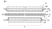
- the heat-resistant layer 24 may be provided on each of the positive electrode 21 and the negative electrode 22 (Modification 5).
- the heat-resistant layer 24 is arranged between the positive electrode 21 and the separator 23 and the heat-resistant layer 24 is arranged between the negative electrode 22 and the separator 23 .
- the heat-resistant layer 24 may be provided only on the negative electrode 22 (Modification 6), or as shown in FIG. The layer 24 may be provided only on the positive electrode 21 (modification 7).
- the heat-resistant layers 24 are provided on both sides of the separator 23, and the heat-resistant layers 24 are provided on each of the positive electrode 21 and the negative electrode 22.
- the heat-resistant layer 24 is used to prevent a short circuit between the positive electrode 21 and the negative electrode 22, so that similar effects can be obtained.
- the electrolyte may contain other electrolyte salts along with the electrolyte salt containing the imide anion.
- the electrolyte contains lithium hexafluorophosphate as another electrolyte salt, and the content of the electrolyte salt in the electrolyte is appropriate in relation to the content of the other electrolyte salts in the electrolyte. It is preferable that the
- the electrolyte salt contains cations and imide anions.
- hexafluorophosphate ions include lithium ions and hexafluorophosphate ions.
- the sum T (mol/kg) of the cation content C1 in the electrolyte and the lithium ion content C2 in the electrolyte is 0.7 mol/kg to 2.2 mol/kg.
- the ratio R (mol %) of the number of moles M2 of the hexafluorophosphate ions in the electrolyte to the number of moles M1 of the imide anions in the electrolyte is 13 mol % to 6000 mol %. This is because the movement speeds of cations and lithium ions are sufficiently improved in the vicinity of the respective surfaces of the positive electrode 21 and the negative electrode 22, and the movement speeds of cations and lithium ions are also sufficiently improved in the liquid electrolyte. be.
- the “content of cations in the electrolyte” described here is the content of the electrolyte salt of cations in the solvent, and the “content of lithium ions in the electrolyte” is the content of lithium ions in the solvent.
- the secondary battery When calculating each of the sum T and the ratio R, the secondary battery is disassembled to collect the electrolytic solution, and then the electrolytic solution is analyzed using ICP emission spectrometry. As a result, the contents C1 and C2 and the numbers of moles M1 and M2 are specified, respectively, so that the sum T and the ratio R are calculated.
- the electrolytic solution contains the electrolyte salt, the same effect can be obtained.
- the electrolyte salt and another electrolyte salt lithium hexafluorophosphate
- the total amount (sum T) of both is optimized, and the mixing ratio (ratio R ) are also optimized.
- the movement speeds of cations and lithium ions in the vicinity of the surfaces of the positive electrode 21 and the negative electrode 22 are further improved, and the movement speeds of cations and lithium ions are further improved in the liquid electrolyte. Therefore, higher effects can be obtained.
- a laminated separator includes a porous membrane having a pair of surfaces and a polymer compound layer provided on one or both sides of the porous membrane. This is because the adhesiveness of the separator to each of the positive electrode 21 and the negative electrode 22 is improved, so that positional deviation (winding deviation) of the battery element 20 is suppressed. As a result, swelling of the secondary battery is suppressed even if a side reaction such as a decomposition reaction of the electrolytic solution occurs.
- the polymer compound layer contains a polymer compound such as polyvinylidene fluoride. This is because excellent physical strength and excellent electrochemical stability can be obtained.
- One or both of the porous membrane and the polymer compound layer may contain a plurality of insulating particles. This is because the safety (heat resistance) of the secondary battery is improved because the plurality of insulating particles promote heat dissipation when the secondary battery generates heat.
- the insulating particles contain one or more of insulating materials such as inorganic materials and resin materials. Specific examples of inorganic materials are aluminum oxide, aluminum nitride, boehmite, silicon oxide, titanium oxide, magnesium oxide and zirconium oxide. Specific examples of resin materials include acrylic resins and styrene resins.
- the precursor solution is applied to one or both sides of the porous membrane.
- a plurality of insulating particles may be added to the precursor solution.
- Modification 11 An electrolytic solution, which is a liquid electrolyte, was used. However, although not specifically illustrated here, an electrolyte layer that is a gel electrolyte may be used.
- the positive electrode 21 and the negative electrode 22 are laminated with the separator 23, the heat-resistant layer 24, and the electrolyte layer interposed therebetween, and the positive electrode 21, the negative electrode 22, the separator 23, the heat-resistant layer 24, and the electrolyte. Layers are wound. This electrolyte layer is interposed between the positive electrode 21 and the separator 23 and interposed between the negative electrode 22 and the separator 23 .
- the electrolyte layer contains a polymer compound together with an electrolytic solution, and the electrolytic solution is held by the polymer compound. This is because leakage of the electrolytic solution is prevented.
- the composition of the electrolytic solution is as described above.
- Polymer compounds include polyvinylidene fluoride and the like.
- a secondary battery used as a power source may be a main power source for electronic devices and electric vehicles, or may be an auxiliary power source.
- a main power source is a power source that is preferentially used regardless of the presence or absence of other power sources.
- the auxiliary power supply may be a power supply used in place of the main power supply, or may be a power supply switched from the main power supply.
- Secondary battery applications are as follows. Electronic devices such as video cameras, digital still cameras, mobile phones, laptop computers, headphone stereos, portable radios and portable information terminals. Backup power and storage devices such as memory cards. Power tools such as power drills and power saws. It is a battery pack mounted on an electronic device. Medical electronic devices such as pacemakers and hearing aids. It is an electric vehicle such as an electric vehicle (including a hybrid vehicle). It is a power storage system such as a home or industrial battery system that stores power in preparation for emergencies. In these uses, one secondary battery may be used, or a plurality of secondary batteries may be used.
- the battery pack may use a single cell or an assembled battery.
- An electric vehicle is a vehicle that operates (runs) using a secondary battery as a drive power source, and may be a hybrid vehicle that also includes a drive source other than the secondary battery.
- household electric power storage system household electric appliances and the like can be used by using electric power stored in a secondary battery, which is an electric power storage source.
- FIG. 12 shows the block configuration of the battery pack.
- the battery pack described here is a battery pack (a so-called soft pack) using one secondary battery, and is mounted in an electronic device such as a smart phone.
- This battery pack includes a power supply 51 and a circuit board 52, as shown in FIG.
- This circuit board 52 is connected to the power supply 51 and includes a positive terminal 53 , a negative terminal 54 and a temperature detection terminal 55 .
- the power supply 51 includes one secondary battery.
- the positive lead is connected to the positive terminal 53 and the negative lead is connected to the negative terminal 54 .
- the power supply 51 can be connected to the outside through the positive terminal 53 and the negative terminal 54, and thus can be charged and discharged.
- the circuit board 52 includes a control section 56 , a switch 57 , a PTC element 58 and a temperature detection section 59 .
- the PTC element 58 may be omitted.
- the control unit 56 includes a central processing unit (CPU), memory, etc., and controls the operation of the entire battery pack. This control unit 56 detects and controls the use state of the power supply 51 as necessary.
- CPU central processing unit
- memory etc.
- the control unit 56 cuts off the switch 57 so that the charging current does not flow through the current path of the power supply 51. make it
- the overcharge detection voltage is not particularly limited, but is specifically 4.20V ⁇ 0.05V, and the overdischarge detection voltage is not particularly limited, but is specifically 2.40V ⁇ 0.1V. is.
- the switch 57 includes a charge control switch, a discharge control switch, a charge diode, a discharge diode, and the like, and switches connection/disconnection between the power supply 51 and an external device according to instructions from the control unit 56 .
- the switch 57 includes a field effect transistor (MOSFET) using a metal oxide semiconductor, etc., and the charge/discharge current is detected based on the ON resistance of the switch 57 .
- MOSFET field effect transistor
- the temperature detection unit 59 includes a temperature detection element such as a thermistor, measures the temperature of the power supply 51 using the temperature detection terminal 55 , and outputs the temperature measurement result to the control unit 56 .
- the measurement result of the temperature measured by the temperature detection unit 59 is used when the control unit 56 performs charging/discharging control at the time of abnormal heat generation and when the control unit 56 performs correction processing when calculating the remaining capacity.
- the laminate film type secondary battery (lithium ion secondary battery) shown in FIGS. 1 and 2 was produced by the following procedure.
- the separator 23 shown in FIG. 3 that is, the separator 23 provided with the heat-resistant layer 24 on both sides was used.
- a positive electrode active material lithium-containing compound (oxide) (LiNi 0.82 Co 0.14 Al 0.04 O 2 ), 3 parts by mass of a positive electrode binder (polyvinylidene fluoride), a positive electrode conductor (carbon 6 parts by mass of black) were mixed with each other to form a positive electrode mixture.
- the positive electrode mixture was added to a solvent (N-methyl-2-pyrrolidone, which is an organic solvent), and the solvent was stirred.
- a coating device both sides of the positive electrode current collector 21A (a strip-shaped aluminum foil having a thickness of 12 ⁇ m) were coated with the positive electrode mixture slurry.
- the positive electrode mixture slurry was dried to form the positive electrode active material layer 21 B.
- the positive electrode active material layer 21 B was compression-molded using a roll press machine, thereby producing the positive electrode 21 .
- a negative electrode active material artificial graphite that is a carbon material
- a negative electrode binder polyvinylidene fluoride
- the organic solvent was stirred to prepare a pasty negative electrode mixture slurry.
- the negative electrode mixture slurry is applied to both surfaces of the negative electrode current collector 22A (band-shaped copper foil having a thickness of 15 ⁇ m) using a coating device, and then the negative electrode mixture slurry is dried to obtain a negative electrode active material.
- a material layer 22B is formed.
- the negative electrode active material layer 22B was compression molded using a roll press. Thus, the negative electrode 22 was produced.
- the polymer compound When a polymer compound was used as the heat-resistant material, the polymer compound was added to the solvent (N-methyl-2-pyrrolidone, which is an organic solvent), and then the solvent was stirred.
- the solvent N-methyl-2-pyrrolidone, which is an organic solvent
- PA1 para-type aromatic polyamide
- PA2 meta-type aromatic polyamide
- the solvent N-methyl-2-pyrrolidone, which is an organic solvent
- the solvent was stirred.
- oxides aluminum oxide (Al 2 O 3 ), titanium oxide (TiO 2 ), and silicon oxide (SiO 2 ) were used.
- PVDF Polyvinylidene fluoride
- PMMA polymethyl methacrylate
- a coated film was formed by applying the solution to both surfaces of the separator 23 (polyethylene microporous membrane having an average pore size of 17.9 nm) using a desktop coater. Finally, the separator 23 was placed in a water bath to cause phase separation of the coating film, and then the coating film was dried with hot air.
- the separator 23 polyethylene microporous membrane having an average pore size of 17.9 nm
- the procedure for producing the polyethylene microporous membrane, which is the separator 23, is as follows. First, a polyethylene solution was prepared by melt-kneading polyethylene and a plasticizer (liquid paraffin) using a twin-screw extruder. Subsequently, while extruding the polyethylene solution from a T-die attached to the tip of the twin-screw extruder, the polyethylene solution was wound up using a cooling roll to form a gel sheet. Subsequently, a thin film was obtained by biaxially stretching the gel-like sheet. Finally, residual liquid paraffin was extracted off by washing the thin film with a solvent (hexane), after which the thin film was dried and heat treated. As a result, the thin film was made microporous, and a microporous polyethylene film was obtained.
- a plasticizer liquid paraffin
- a heat-resistant layer was prepared according to the same procedure except that a non-heat-resistant material (polyethylene (PE), which is a polymer compound) was used instead of the heat-resistant material. 24 was formed.
- PE polyethylene
- Ethylene carbonate which is a cyclic carbonate
- ⁇ -butyrolactone which is a lactone
- Lithium ions (Li + ) were used as cations of the electrolyte salt.
- the anions of the electrolyte salt include the first imide anions shown in formulas (1-5), (1-6), formulas (1-21) and formulas (1-22), and formula (2-5 ), the tertiary imide anion represented by formula (3-5), and the quaternary imide anion represented by formula (4-37).
- the electrolyte salt content (mol/kg) was as shown in Tables 1 and 2.
- This electrolyte salt is a lithium salt containing an imide anion as an anion.
- the positive electrode lead 31 (aluminum foil) was welded to the positive electrode collector 21A of the positive electrode 21, and the negative electrode lead 32 (copper foil) was welded to the negative electrode collector 22A.
- the positive electrode 21 and the negative electrode 22 are laminated with each other via the separator 23 provided with the heat-resistant layer 24, and then the positive electrode 21, the negative electrode 22, the separator 23 and the heat-resistant layer 24 are wound to form a wound body. was made. Subsequently, the wound body was formed into a flat shape by pressing the wound body using a pressing machine.
- the exterior film 10 includes a fusion layer (a polypropylene film with a thickness of 30 ⁇ m), a metal layer (aluminum foil with a thickness of 40 ⁇ m), and a surface protective layer (a nylon film with a thickness of 25 ⁇ m). Aluminum laminate films laminated in this order from the inside were used.
- constant-current charging was performed at a current of 0.1C until the voltage reached 4.2V
- constant-voltage charging was performed at the voltage of 4.2V until the current reached 0.05C.
- constant current discharge was performed at a current of 0.1C until the voltage reached 2.5V.
- 0.1C is a current value that can fully discharge the battery capacity (theoretical capacity) in 10 hours
- 0.05C is a current value that fully discharges the battery capacity in 20 hours.
- the charging/discharging conditions were the same as the charging/discharging conditions during stabilization of the secondary battery described above.
- the secondary battery was repeatedly charged and discharged in the same environment until the total number of cycles reached 100 cycles, thereby measuring the discharge capacity (discharge capacity at the 100th cycle).
- the charging/discharging conditions were the same as the charging/discharging conditions during stabilization of the secondary battery described above.
- cycle retention rate (%) (discharge capacity at 100th cycle/discharge capacity at 1st cycle) x 100 is used to calculate the cycle retention rate, which is an index for evaluating high-temperature cycle characteristics. bottom.
- the charging/discharging conditions were the same as the charging/discharging conditions during stabilization of the secondary battery described above.
- the secondary battery is stored in a normal temperature environment.
- the discharge capacity discharge capacity after storage was measured by discharging the battery.
- the charging/discharging conditions were the same as the charging/discharging conditions during stabilization of the secondary battery described above.
- the storage retention rate (%) (discharge capacity after storage/discharge capacity before storage) x 100 was used to calculate the storage retention rate, which is an index for evaluating high-temperature storage characteristics.
- the charging/discharging conditions were the same as the charging/discharging conditions during stabilization of the secondary battery described above.
- the charge/discharge conditions were the same as the charge/discharge conditions during stabilization of the secondary battery described above, except that the current during discharge was changed to 1C.
- 1C is a current value that can discharge the battery capacity in 1 hour.
- load retention rate (discharge capacity at 100th cycle/discharge capacity at 1st cycle) x 100. bottom.
- the cycle retention rate, the storage retention rate, and the load retention rate are Both decreased.
- the cycle retention rate, the storage retention rate, and the load retention rate are Both increased.
- Examples 25 to 42> As shown in Tables 3 and 4, secondary batteries were produced in the same manner as in Example 3, except that the electrolytic solution contained either additives or other electrolyte salts. , evaluated the battery characteristics. In this case, either the additive or the other electrolyte salt was added to the solvent containing the electrolyte salt, and then the solvent was stirred.
- Vinylene carbonate (VC), vinyl ethylene carbonate (VEC) and methylene ethylene carbonate (MEC) were used as the unsaturated cyclic carbonate.
- fluorinated cyclic carbonate ethylene monofluorocarbonate (FEC) and ethylene difluorocarbonate (DFEC) were used.
- FEC ethylene monofluorocarbonate
- DFEC ethylene difluorocarbonate
- sulfonic acid esters propanesultone (PS) and propenesultone (PRS), which are cyclic monosulfonic acid esters, and cyclodison (CD), which is a cyclic disulfonic acid ester, were used.
- Succinic anhydride (SA) was used as the dicarboxylic anhydride.
- PSAH Propanedisulfonic anhydride
- DTD Ethylene sulfate
- Succinonitrile SN
- HMI Hexamethylene diisocyanate
- electrolyte salts include lithium hexafluorophosphate ( LiPF6 ), lithium tetrafluoroborate ( LiBF4 ), lithium bis(fluorosulfonyl)imide (LiFSI), lithium bis(oxalato)borate (LiBOB). and lithium difluorophosphate (LiPF 2 O 2 ) were used.
- LiPF6 lithium hexafluorophosphate
- LiBF4 lithium tetrafluoroborate
- LiFSI lithium bis(fluorosulfonyl)imide
- LiBOB lithium bis(oxalato)borate
- LiPF 2 O 2 lithium difluorophosphate
- Examples 43 to 74> As shown in Tables 5 and 6, a secondary battery was prepared in the same manner as in Example 3 except that the electrolyte solution contained another electrolyte salt (lithium hexafluorophosphate (LiPF 6 )). was produced, and the battery characteristics were evaluated.
- the electrolyte solution contained another electrolyte salt (lithium hexafluorophosphate (LiPF 6 )). was produced, and the battery characteristics were evaluated.
- LiPF 6 lithium hexafluorophosphate
- the heat-resistant layer 24 is arranged at least in the facing region R between the positive electrode 21 and the negative electrode 22, the heat-resistant layer 24 contains a heat-resistant material, and the electrolyte solution Cycle retention rate, storage retention rate and load retention rate were all improved when the electrolyte salt contained an imide anion. Therefore, excellent high-temperature cycle characteristics, excellent high-temperature storage characteristics, and excellent low-temperature load characteristics were obtained in the secondary battery, and thus excellent battery characteristics could be obtained.
- the element structure of the battery element is a wound type.
- the element structure of the battery element is not particularly limited, it may be a laminated type or a folded type.
- the positive electrode and the negative electrode are alternately laminated with a separator interposed therebetween, and in the multifold type, the positive electrode and the negative electrode are folded zigzag while facing each other with the separator interposed therebetween.
Landscapes
- Chemical & Material Sciences (AREA)
- Chemical Kinetics & Catalysis (AREA)
- Electrochemistry (AREA)
- General Chemical & Material Sciences (AREA)
- Engineering & Computer Science (AREA)
- Inorganic Chemistry (AREA)
- Manufacturing & Machinery (AREA)
- General Physics & Mathematics (AREA)
- Condensed Matter Physics & Semiconductors (AREA)
- Physics & Mathematics (AREA)
- Materials Engineering (AREA)
- Composite Materials (AREA)
- Ceramic Engineering (AREA)
- Secondary Cells (AREA)
Priority Applications (3)
| Application Number | Priority Date | Filing Date | Title |
|---|---|---|---|
| CN202280081984.3A CN118382950A (zh) | 2021-12-24 | 2022-12-23 | 二次电池 |
| JP2023569561A JPWO2023120687A1 (https=) | 2021-12-24 | 2022-12-23 | |
| US18/732,843 US20240339653A1 (en) | 2021-12-24 | 2024-06-04 | Secondary battery |
Applications Claiming Priority (2)
| Application Number | Priority Date | Filing Date | Title |
|---|---|---|---|
| JP2021210398 | 2021-12-24 | ||
| JP2021-210398 | 2021-12-24 |
Related Child Applications (1)
| Application Number | Title | Priority Date | Filing Date |
|---|---|---|---|
| US18/732,843 Continuation US20240339653A1 (en) | 2021-12-24 | 2024-06-04 | Secondary battery |
Publications (1)
| Publication Number | Publication Date |
|---|---|
| WO2023120687A1 true WO2023120687A1 (ja) | 2023-06-29 |
Family
ID=86902818
Family Applications (1)
| Application Number | Title | Priority Date | Filing Date |
|---|---|---|---|
| PCT/JP2022/047544 Ceased WO2023120687A1 (ja) | 2021-12-24 | 2022-12-23 | 二次電池 |
Country Status (4)
| Country | Link |
|---|---|
| US (1) | US20240339653A1 (https=) |
| JP (1) | JPWO2023120687A1 (https=) |
| CN (1) | CN118382950A (https=) |
| WO (1) | WO2023120687A1 (https=) |
Cited By (1)
| Publication number | Priority date | Publication date | Assignee | Title |
|---|---|---|---|---|
| WO2026016448A1 (zh) * | 2024-07-15 | 2026-01-22 | 宁德时代新能源科技股份有限公司 | 隔离膜、二次电池单体、电池装置和用电装置 |
Citations (3)
| Publication number | Priority date | Publication date | Assignee | Title |
|---|---|---|---|---|
| JP2013222582A (ja) * | 2012-04-16 | 2013-10-28 | Sony Corp | 二次電池、電池パック、電動車両、電力貯蔵システム、電動工具および電子機器 |
| JP2014516201A (ja) * | 2011-06-07 | 2014-07-07 | スリーエム イノベイティブ プロパティズ カンパニー | フルオロカーボン電解質添加剤を含むリチウムイオン電気化学電池 |
| CN112420998A (zh) * | 2019-08-22 | 2021-02-26 | 宁德时代新能源科技股份有限公司 | 一种二次电池 |
Family Cites Families (1)
| Publication number | Priority date | Publication date | Assignee | Title |
|---|---|---|---|---|
| JP7024791B2 (ja) * | 2017-07-24 | 2022-02-24 | 株式会社村田製作所 | 二次電池用負極、二次電池、電池パック、電動車両、電力貯蔵システム、電動工具および電子機器 |
-
2022
- 2022-12-23 JP JP2023569561A patent/JPWO2023120687A1/ja active Pending
- 2022-12-23 CN CN202280081984.3A patent/CN118382950A/zh active Pending
- 2022-12-23 WO PCT/JP2022/047544 patent/WO2023120687A1/ja not_active Ceased
-
2024
- 2024-06-04 US US18/732,843 patent/US20240339653A1/en active Pending
Patent Citations (3)
| Publication number | Priority date | Publication date | Assignee | Title |
|---|---|---|---|---|
| JP2014516201A (ja) * | 2011-06-07 | 2014-07-07 | スリーエム イノベイティブ プロパティズ カンパニー | フルオロカーボン電解質添加剤を含むリチウムイオン電気化学電池 |
| JP2013222582A (ja) * | 2012-04-16 | 2013-10-28 | Sony Corp | 二次電池、電池パック、電動車両、電力貯蔵システム、電動工具および電子機器 |
| CN112420998A (zh) * | 2019-08-22 | 2021-02-26 | 宁德时代新能源科技股份有限公司 | 一种二次电池 |
Cited By (1)
| Publication number | Priority date | Publication date | Assignee | Title |
|---|---|---|---|---|
| WO2026016448A1 (zh) * | 2024-07-15 | 2026-01-22 | 宁德时代新能源科技股份有限公司 | 隔离膜、二次电池单体、电池装置和用电装置 |
Also Published As
| Publication number | Publication date |
|---|---|
| CN118382950A (zh) | 2024-07-23 |
| JPWO2023120687A1 (https=) | 2023-06-29 |
| US20240339653A1 (en) | 2024-10-10 |
Similar Documents
| Publication | Publication Date | Title |
|---|---|---|
| WO2022163138A1 (ja) | 二次電池用電解液および二次電池 | |
| JP7459960B2 (ja) | 二次電池用電解液および二次電池 | |
| WO2022196266A1 (ja) | 二次電池 | |
| US20240339653A1 (en) | Secondary battery | |
| WO2023120688A1 (ja) | 二次電池 | |
| JP7517480B2 (ja) | 二次電池 | |
| CN118369804A (zh) | 二次电池 | |
| JP7715210B2 (ja) | 二次電池用電解液および二次電池 | |
| JP7726276B2 (ja) | 二次電池用電解液および二次電池 | |
| JP7761127B2 (ja) | 二次電池用電解液および二次電池 | |
| JP7715211B2 (ja) | 二次電池用電解液および二次電池 | |
| JP7761126B2 (ja) | 二次電池用電解液および二次電池 | |
| JP7694715B2 (ja) | 二次電池 | |
| JP7761128B2 (ja) | 二次電池 | |
| JP7694716B2 (ja) | 二次電池 | |
| JP7750378B2 (ja) | 二次電池用電解液および二次電池 | |
| JP7715362B2 (ja) | 二次電池用電解液および二次電池 | |
| WO2024190050A1 (ja) | 二次電池用電解液および二次電池 | |
| WO2022196238A1 (ja) | 二次電池用電解液および二次電池 | |
| WO2023162428A1 (ja) | 二次電池 | |
| WO2024195306A1 (ja) | 二次電池 | |
| WO2024262634A1 (ja) | 二次電池 | |
| WO2022172718A1 (ja) | 二次電池 | |
| WO2024195303A1 (ja) | 二次電池 | |
| CN120345095A (zh) | 锂离子二次电池用电解液以及锂离子二次电池 |
Legal Events
| Date | Code | Title | Description |
|---|---|---|---|
| 121 | Ep: the epo has been informed by wipo that ep was designated in this application |
Ref document number: 22911389 Country of ref document: EP Kind code of ref document: A1 |
|
| WWE | Wipo information: entry into national phase |
Ref document number: 202280081984.3 Country of ref document: CN |
|
| WWE | Wipo information: entry into national phase |
Ref document number: 2023569561 Country of ref document: JP |
|
| NENP | Non-entry into the national phase |
Ref country code: DE |
|
| 122 | Ep: pct application non-entry in european phase |
Ref document number: 22911389 Country of ref document: EP Kind code of ref document: A1 |