WO2023120598A1 - 情報処理システム、プログラム、及び情報処理方法 - Google Patents
情報処理システム、プログラム、及び情報処理方法 Download PDFInfo
- Publication number
- WO2023120598A1 WO2023120598A1 PCT/JP2022/047198 JP2022047198W WO2023120598A1 WO 2023120598 A1 WO2023120598 A1 WO 2023120598A1 JP 2022047198 W JP2022047198 W JP 2022047198W WO 2023120598 A1 WO2023120598 A1 WO 2023120598A1
- Authority
- WO
- WIPO (PCT)
- Prior art keywords
- excavator
- display
- information processing
- image data
- captured
- Prior art date
- Legal status (The legal status is an assumption and is not a legal conclusion. Google has not performed a legal analysis and makes no representation as to the accuracy of the status listed.)
- Ceased
Links
Images





Classifications
-
- H—ELECTRICITY
- H04—ELECTRIC COMMUNICATION TECHNIQUE
- H04N—PICTORIAL COMMUNICATION, e.g. TELEVISION
- H04N23/00—Cameras or camera modules comprising electronic image sensors; Control thereof
- H04N23/90—Arrangement of cameras or camera modules, e.g. multiple cameras in TV studios or sports stadiums
-
- E—FIXED CONSTRUCTIONS
- E02—HYDRAULIC ENGINEERING; FOUNDATIONS; SOIL SHIFTING
- E02F—DREDGING; SOIL-SHIFTING
- E02F9/00—Component parts of dredgers or soil-shifting machines, not restricted to one of the kinds covered by groups E02F3/00 - E02F7/00
-
- E—FIXED CONSTRUCTIONS
- E02—HYDRAULIC ENGINEERING; FOUNDATIONS; SOIL SHIFTING
- E02F—DREDGING; SOIL-SHIFTING
- E02F9/00—Component parts of dredgers or soil-shifting machines, not restricted to one of the kinds covered by groups E02F3/00 - E02F7/00
- E02F9/20—Drives; Control devices
- E02F9/2025—Particular purposes of control systems not otherwise provided for
- E02F9/205—Remotely operated machines, e.g. unmanned vehicles
-
- E—FIXED CONSTRUCTIONS
- E02—HYDRAULIC ENGINEERING; FOUNDATIONS; SOIL SHIFTING
- E02F—DREDGING; SOIL-SHIFTING
- E02F9/00—Component parts of dredgers or soil-shifting machines, not restricted to one of the kinds covered by groups E02F3/00 - E02F7/00
- E02F9/26—Indicating devices
-
- E—FIXED CONSTRUCTIONS
- E02—HYDRAULIC ENGINEERING; FOUNDATIONS; SOIL SHIFTING
- E02F—DREDGING; SOIL-SHIFTING
- E02F9/00—Component parts of dredgers or soil-shifting machines, not restricted to one of the kinds covered by groups E02F3/00 - E02F7/00
- E02F9/26—Indicating devices
- E02F9/261—Surveying the work-site to be treated
-
- H—ELECTRICITY
- H04—ELECTRIC COMMUNICATION TECHNIQUE
- H04M—TELEPHONIC COMMUNICATION
- H04M11/00—Telephonic communication systems specially adapted for combination with other electrical systems
-
- H—ELECTRICITY
- H04—ELECTRIC COMMUNICATION TECHNIQUE
- H04N—PICTORIAL COMMUNICATION, e.g. TELEVISION
- H04N13/00—Stereoscopic video systems; Multi-view video systems; Details thereof
- H04N13/10—Processing, recording or transmission of stereoscopic or multi-view image signals
- H04N13/106—Processing image signals
- H04N13/156—Mixing image signals
-
- H—ELECTRICITY
- H04—ELECTRIC COMMUNICATION TECHNIQUE
- H04N—PICTORIAL COMMUNICATION, e.g. TELEVISION
- H04N13/00—Stereoscopic video systems; Multi-view video systems; Details thereof
- H04N13/20—Image signal generators
- H04N13/282—Image signal generators for generating image signals corresponding to three or more geometrical viewpoints, e.g. multi-view systems
-
- H—ELECTRICITY
- H04—ELECTRIC COMMUNICATION TECHNIQUE
- H04N—PICTORIAL COMMUNICATION, e.g. TELEVISION
- H04N7/00—Television systems
- H04N7/18—Closed-circuit television [CCTV] systems, i.e. systems in which the video signal is not broadcast
-
- H—ELECTRICITY
- H04—ELECTRIC COMMUNICATION TECHNIQUE
- H04N—PICTORIAL COMMUNICATION, e.g. TELEVISION
- H04N7/00—Television systems
- H04N7/18—Closed-circuit television [CCTV] systems, i.e. systems in which the video signal is not broadcast
- H04N7/181—Closed-circuit television [CCTV] systems, i.e. systems in which the video signal is not broadcast for receiving images from a plurality of remote sources
-
- H—ELECTRICITY
- H04—ELECTRIC COMMUNICATION TECHNIQUE
- H04Q—SELECTING
- H04Q9/00—Arrangements in telecontrol or telemetry systems for selectively calling a substation from a main station, in which substation desired apparatus is selected for applying a control signal thereto or for obtaining measured values therefrom
-
- B—PERFORMING OPERATIONS; TRANSPORTING
- B60—VEHICLES IN GENERAL
- B60Y—INDEXING SCHEME RELATING TO ASPECTS CROSS-CUTTING VEHICLE TECHNOLOGY
- B60Y2200/00—Type of vehicle
- B60Y2200/40—Special vehicles
- B60Y2200/41—Construction vehicles, e.g. graders, excavators
- B60Y2200/412—Excavators
Definitions
- the present invention relates to an information processing system, a program, and an information processing method.
- Patent Literature 1 provides a technique for recording the surrounding situation as a moving image after determining whether or not an accident has occurred.
- One aspect of the present invention provides a technology that facilitates understanding of the situation of the work site by imaging the work site with an imaging device provided on the work machine and displaying based on the captured image data.
- An information processing system is an information processing system including an excavator equipped with an imaging device and an information processing device, wherein an image captured by the imaging device is associated with the image. Further, data including at least one of direction, time, and position is transmitted from the excavator to the information processing device, and the information processing device responds to the designation of at least one of direction, time, and position, Control is performed to display an image associated with at least one of the specified direction, time, and position.
- FIG. 1 is a schematic diagram showing an example of the configuration of a peripheral image management system according to an embodiment.
- FIG. 2 is a diagram illustrating an example of the configuration of the shovel according to the embodiment;
- FIG. 3 is a top view of the excavator according to the embodiment.
- FIG. 4 is a configuration diagram showing an example of the configuration of the peripheral image management system according to the embodiment.
- FIG. 5 is a diagram exemplifying transmission data including captured image data transmitted by a transmission processing unit according to the embodiment;
- FIG. 6 is a diagram showing positions at which the excavator according to the embodiment performs imaging.
- FIG. 7 is a diagram illustrating a concept of combining captured image data to generate bird's-eye view image data by a synthesizing unit according to the embodiment.
- FIG. 8 is a diagram illustrating an example of bird's-eye view image data generated by a synthesizing unit according to the embodiment
- FIG. FIG. 9 is a diagram showing a work site list screen displayed by the image display processing unit according to the embodiment.
- FIG. 10 is a diagram showing a work site list screen displayed by the image display processing unit according to the embodiment.
- 11 is a diagram exemplifying a display screen displayed by an image display processing unit according to the embodiment;
- FIG. 12 is a diagram exemplifying a display screen displayed by an image display processing unit according to the embodiment;
- FIG. FIG. 13 is a sequence diagram showing a processing procedure up to saving composite image data in the peripheral image management system according to the embodiment.
- FIG. 14 is a flowchart showing a processing procedure for displaying display image data representing a work site in the communication terminal according to the embodiment.
- FIG. 15 is a flowchart showing a processing procedure up to transmission of display image data in the management device according to the embodiment.
- peripheral image management system SYS an example of an information processing system
- FIG. 1 is a schematic diagram showing an example of the configuration of the peripheral image management system SYS according to this embodiment.
- the peripheral image management system SYS is a system for managing images of a work site (an example of a predetermined range) where the excavator 100 is working. including.
- the peripheral image management system SYS manages image data captured by the imaging device 40 provided on the excavator 100 .
- the excavator 100 included in the peripheral image management system SYS may be one or plural.
- the number of communication terminals 400 included in the peripheral image management system SYS may be one or plural.
- the peripheral image management system SYS manages images of the work site, thereby facilitating grasping the situation of the work site where the excavator 100 works.
- the captured image data captured by the excavator 100 is transmitted to the management device 300 .
- the management device 300 manages the received captured image data as a surrounding image of the work site where the excavator 100 is working.
- the communication terminal 400 receives image data or the like showing the surroundings of the work site from the management device 300, so that the situation around the work site can be grasped.
- the excavator 100 includes a lower traveling body 1, an upper rotating body 3 mounted on the lower traveling body 1 so as to be rotatable (rotatable) via a turning mechanism 2, and a boom 4, an arm 5, and a bucket 6 as attachments. , cabin 10 and the like.
- the lower traveling body 1 includes, for example, a pair of left and right crawlers 1CL and 1CR (see FIG. 3), and the respective crawlers are hydraulically driven by traveling hydraulic motors 1L and 1R (see FIG. 2) to travel the excavator 100.
- the upper revolving structure 3 revolves with respect to the lower traveling structure 1 by being driven by a revolving hydraulic motor 2A (see FIG. 2).
- the boom 4 is pivotally attached to the center of the front portion of the upper rotating body 3 so as to be able to be raised.
- An arm 5 is pivotally attached to the tip of the boom 4 so as to be vertically rotatable. rotatably pivoted;
- the boom 4, arm 5 and bucket 6 are hydraulically driven by a boom cylinder 7, an arm cylinder 8 and a bucket cylinder 9 as hydraulic actuators, respectively.
- the bucket 6 is an example of an end attachment
- the excavator 100 includes an end attachment of a different type from the bucket 6 (for example, a crusher, a lifting magnet, etc., an end attachment with a different application from the bucket 6, a large bucket, etc.).
- an end attachment that differs from the bucket 6 in specifications other than the application) may be attached.
- the excavator 100 may be configured such that the type of end attachment can be exchanged as appropriate according to the type of work or the like.
- the cabin 10 is a cockpit in which an operator boards, and an operating device 26 (see FIG. 2) and the like are provided inside.
- the cabin 10 is mounted on the front left side of the upper swing body 3, for example.
- the excavator 100 includes communication equipment 60 for communicating with a predetermined communication network NW.
- the communication device 60 of the excavator 100 communicates with the management device 300 through a predetermined communication network NW.
- the communication network NW may include, for example, a mobile communication network with base stations as terminals. Also, the communication network NW may include a satellite communication network using a communication satellite in the sky. Also, the communication network NW may include the Internet or the like. The communication network NW may also include a short-range communication network conforming to protocols such as Wi-Fi (registered trademark) and Bluetooth (registered trademark).
- Wi-Fi registered trademark
- Bluetooth registered trademark
- the excavator 100 operates actuators to drive driven elements such as the lower traveling body 1, the upper revolving body 3, the boom 4, the arm 5, and the bucket 6, according to the operation of the operator riding in the cabin 10.
- the excavator 100 may automatically operate the hydraulic actuator regardless of the details of the operator's operation.
- the excavator 100 may realize a function of automatically operating at least some of the driven elements such as the lower traveling body 1, the upper revolving body 3, the boom 4, the arm 5, and the bucket 6.
- the excavator 100 includes a display device 50.
- the display device 50 of the excavator 100 displays captured image data captured by the imaging device 40 .
- the operator boarding the cabin 10 can grasp the situation around the excavator 100 .
- the excavator 100 is equipped with four imaging devices 40 .
- the imaging device 40 includes, for example, a monocular camera, a stereo camera, a depth camera, and the like. Furthermore, the imaging device 40 may be any device capable of imaging the surroundings of the excavator 100, and may be a drive recorder, for example. Furthermore, the captured image data captured by the imaging device 40 may be a still image or a moving image.
- the four imaging devices 40 are provided so as to image the surroundings of the excavator 100 .
- the imaging device 40 according to this embodiment is provided with a wide-angle lens.
- the imaging devices 40 of the excavator 100 include an imaging device 40B that images the front of the upper revolving body 3, an imaging device 40B that images the rear of the upper revolving body 3, an imaging device 40L that images the left side of the upper revolving body 3, and an imaging device 40R (not shown in FIG. 1) for imaging the right side of the upper rotating body 3. As shown in FIG.
- the captured image data captured by the imaging device 40 is transmitted to the controller 30 .
- the controller 30 then associates the captured image data with various types of information indicating the state of the excavator 100 and transmits the associated information to the management device 300 via the communication device 60 .
- a management device 300 (an example of an information processing device) is arranged at a position geographically separated from a user or the like possessing the excavator 100 and the communication terminal 400 .
- the management device 300 is, for example, a server device that is installed in a management center or the like provided outside the work site where the excavator 100 works, and that is mainly composed of one or a plurality of server computers or the like.
- the server device may be an in-house server operated by a company that operates the peripheral image management system SYS or a related company related to the company, or may be a rental server.
- this server device may be a so-called cloud server.
- the management device 300 may be a server device (so-called edge server) arranged in a management office or the like in the work site of the excavator 100, or may be a stationary or portable general-purpose computer terminal. good.
- the management device 300 can mutually communicate with each of the excavator 100 and the communication terminal 400 through the communication network NW. Thereby, the management device 300 can manage image data and the like received from the excavator 100 . Similarly, the management device 300 can transmit managed image data and the like to the communication terminal 400 .
- a communication terminal 400 (an example of an information processing device) is a user terminal used by a user, and stores information (including image data) indicating the situation of a work site (an example of a predetermined range) where the excavator 100 is working. accept the offer.
- Users may include, for example, worksite supervisors, managers, excavator 100 operators, excavator 100 managers, excavator 100 service personnel, excavator 100 developers, and the like.
- the communication terminal 400 is, for example, a general-purpose portable terminal such as a laptop computer terminal, a tablet terminal, or a smartphone owned by the user.
- Communication terminal 400 may also be a stationary general-purpose terminal such as a desktop computer.
- the communication terminal 400 can mutually communicate with the management device 300 through the communication network NW. Thereby, the communication terminal 400 receives the image data indicating the situation of the work site transmitted from the management device 300, and displays the situation of the work site on the display device mounted on the own device.
- the communication terminal 400 may be configured to be able to communicate with the excavator 100 through the communication network NW.
- FIG. 2 is a diagram showing an example of the configuration of the shovel 100 according to this embodiment.
- mechanical power lines are indicated by double lines
- hydraulic oil lines are indicated by solid lines
- pilot lines are indicated by broken lines
- electric drive/control lines are indicated by dotted lines.
- a hydraulic drive system for hydraulically driving the hydraulic actuator in the excavator 100 according to the present embodiment includes an engine 11, a regulator 13, a main pump 14, and a control valve 17.
- the hydraulic drive system of the excavator 100 according to the present embodiment includes hydraulic actuators such as the traveling hydraulic motors 1L and 1R, the turning hydraulic motor 2A, the boom cylinder 7, the arm cylinder 8, and the bucket cylinder 9.
- Hydraulic actuators such as the traveling hydraulic motors 1L and 1R, the swing hydraulic motor 2A, the boom cylinder 7, the arm cylinder 8, and the bucket cylinder 9 are connected to the lower traveling structure 1, the upper swing structure 3, the boom 4, the arm 5, and the bucket. 6 are hydraulically driven.
- the engine 11 is the main power source in the hydraulic drive system, and is mounted on the rear portion of the upper revolving body 3, for example.
- the engine 11 is, for example, a diesel engine that uses light oil as fuel. Specifically, the engine 11 rotates at a predetermined target rotation speed to drive the main pump 14 and the pilot pump 15 under direct or indirect control by the controller 30 to be described later.
- the regulator 13 adjusts the discharge amount of the main pump 14 under the control of the controller 30 .
- the regulator 13 adjusts the angle of the swash plate of the main pump 14 (hereinafter referred to as “tilt angle”) according to a control command from the controller 30 .
- the main pump 14 is mounted, for example, on the rear portion of the upper revolving body 3 in the same manner as the engine 11, and supplies hydraulic oil to the control valve 17 through the hydraulic oil line.
- the main pump 14 is driven by the engine 11 as described above.
- the main pump 14 is, for example, a variable displacement hydraulic pump, and as described above, under the control of the controller 30, the regulator 13 adjusts the tilting angle of the swash plate, thereby adjusting the stroke length of the piston and discharging.
- the flow rate (discharge pressure) is controlled.
- the control valve 17 is, for example, a hydraulic control device that is mounted in the central portion of the upper revolving body 3 and that controls the hydraulic drive system according to the operation of the operating device 26 by the operator. As described above, the control valve 17 is connected to the main pump 14 via the hydraulic fluid line, and operates the hydraulic fluid supplied from the main pump 14 according to the operating state of the operating device 26 to the hydraulic actuator (traveling hydraulic motor 1L). , 1R, swing hydraulic motor 2A, boom cylinder 7, arm cylinder 8, and bucket cylinder 9). Specifically, the control valve 17 includes a plurality of control valves that control the flow rate and flow direction of hydraulic oil supplied from the main pump 14 to each of the hydraulic actuators.
- An operating system for various operating elements (hydraulic actuators) in the excavator 100 includes a pilot pump 15 and an operating device 26 .
- the pilot pump 15 is mounted, for example, on the rear portion of the upper revolving body 3, and supplies pilot pressure to the operating device 26 via a pilot line.
- the pilot pump 15 is, for example, a fixed displacement hydraulic pump, and is driven by the engine 11 as described above.
- the operation device 26 is provided near the cockpit of the cabin 10, and is an operation input means for the operator to operate various operation elements (lower traveling body 1, upper rotating body 3, boom 4, arm 5, bucket 6, etc.). is.
- the operation device 26 allows the operator to operate the hydraulic actuators (that is, the traveling hydraulic motors 1L and 1R, the turning hydraulic motor 2A, the boom cylinder 7, the arm cylinder 8, the bucket cylinder 9, etc.) that drive the respective operating elements.
- the operation device 26 is, for example, a hydraulic pilot type, and is connected to the control valve 17 through a secondary side pilot line.
- the control valve 17 is supplied with a pilot pressure corresponding to the operation state of the lower traveling body 1, the upper rotating body 3, the boom 4, the arm 5, the bucket 6, and the like in the operating device 26.
- FIG. Therefore, the control valve 17 can selectively drive each hydraulic actuator according to the operating state of the operating device 26 .
- the operation device 26 is, for example, a lever device that operates attachments, that is, the operations of the boom 4 (boom cylinder 7), the arm 5 (arm cylinder 8), the bucket 6 (bucket cylinder 9), and the swinging operation of the upper rotating body. including.
- the operating device 26 includes, for example, a pedal device or a lever device for operating each of the left and right lower traveling bodies 1 (traveling hydraulic motors 1L, 1R).
- the operation device 26 may be of an electric type.
- the operation device 26 outputs an electric signal (hereinafter referred to as an “operation signal”) representing the operation content (for example, operation amount and operation direction), and the operation signal is taken into the controller 30, for example.
- the controller 30 then outputs an operation command corresponding to the operation signal to a hydraulic control valve (for example, a hydraulic control valve 31 described later) installed in a pilot line between the pilot pump 15 and the control valve 17 .
- a pilot pressure corresponding to the operation content of the operating device 26 acts on the control valve 17 from the hydraulic control valve.
- the controller 30 can cause the control valve 17 to operate according to the operation content of the operating device 26 .
- the operation signal output from the operating device 26 may be directly input to the various control valves of the control valve 17.
- the various hydraulic actuators may be replaced with electric actuators, and the excavator 100 may be a hybrid excavator or an electric excavator.
- the control system of the excavator 100 includes a controller 30, a boom bottom pressure sensor 7a, a pressure reducing valve 26V, an operating pressure sensor 29, a display device 50, an input device 52, an audio output device 44, It includes a GPS unit 46 , a timing device 48 and four imaging devices 40 .
- the controller 30 is provided in the cabin 10, for example, and controls the drive of the shovel 100.
- the functions of the controller 30 may be realized by arbitrary hardware, software, or a combination thereof.
- the controller 30 is mainly a microcomputer including a CPU (Central Processing Unit), a ROM (Read Only Memory), a RAM (Random Access Memory), a non-volatile auxiliary storage device, various input/output interfaces, etc. Configured.
- the controller 30 implements various functions by executing, on the CPU, various programs stored in, for example, a ROM or a nonvolatile auxiliary storage device.
- the boom bottom pressure sensor 7a is attached to the boom cylinder 7 and detects the pressure of the bottom side oil chamber (hereinafter referred to as "boom bottom pressure"). A detection signal corresponding to the boom bottom pressure detected by the boom bottom pressure sensor 7 a is taken into the controller 30 .
- the pressure reducing valve 26V is provided in the pilot line on the secondary side of the operation device 26, and can reduce the pilot pressure corresponding to the operation state (for example, operation amount and operation direction) of the operation device 26 under the control of the controller 30.
- the pressure reducing valve 26V is provided by individual operation means such as a lever device or a pedal device corresponding to each of a plurality of operating elements (that is, a plurality of hydraulic actuators that drive these operating elements) included in the operating device 26. provided for all.
- the pressure reducing valve 26V does not reduce the pilot pressure output from the operation device 26, and causes the pressure to act on the control valve 17 as it is.
- the pressure reducing valve 26V reduces the pilot pressure output from the operating device 26 according to the magnitude of the control current, and transfers the reduced pilot pressure to the control valve 17. act.
- the controller 30 can limit the operation of the hydraulic actuator corresponding to the operation content of the operating device 26 by the operator or the like, that is, the operation of the operating element driven by the hydraulic actuator.
- the operation pressure sensor 29 detects the pilot pressure on the secondary side of the operation device 26 , that is, the pilot pressure corresponding to the operation state of each operating element (hydraulic actuator) in the operation device 26 . Pilot pressure detection signals corresponding to operation contents (operation states) of the lower traveling body 1, upper swing body 3, boom 4, arm 5, bucket 6, etc. in the operation device 26 by the operation pressure sensor 29 are taken into the controller 30.
- the display device 50 is provided at a location within the cabin 10 that is easily visible to a seated operator, and displays various information images under the control of the controller 30 .
- the display device 50 may be connected to the controller 30 via an in-vehicle communication network such as CAN (Controller Area Network), or may be connected to the controller 30 via a one-to-one dedicated line.
- CAN Controller Area Network
- the input device 52 is provided within the reach of the seated operator in the cabin 10 , receives various operational inputs from the operator, and outputs signals to the controller 30 according to the operational inputs.
- the input device 52 includes, for example, a touch panel mounted on a display of a display device that displays various information images, a knob switch provided at the tip of a lever portion of a lever device included in the operation device 26, and a knob switch installed around the display device 50. may include button switches, levers, toggles, dials, etc.
- the voice output device 44 is provided inside the cabin 10 and outputs various voices under the control of the controller 30 .
- the audio output device 44 is, for example, a speaker, buzzer, or the like.
- the imaging device 40 is attached to the upper part of the upper revolving body 3, images the surroundings of the excavator 100, and outputs the captured image.
- the imaging device 40 includes imaging devices 40F, 40B, 40L, and 40R.
- the imaging devices 40F, 40B, 40L, and 40R are attached to the upper front end (for example, the upper front end of the cabin 10), the upper rear end, the upper left end, and the upper right end of the upper revolving body 3. Images of the front, back, left side, and right side of the body 3 are taken.
- the imaging devices 40F, 40B, 40L, and 40R are monocular wide-angle cameras each having a very wide angle of view.
- the imaging devices 40F, 40B, 40L, and 40R are each mounted in the upper part of the upper revolving body 3 so that the optical axis is directed obliquely downward, and the imaging devices 40F, 40B, 40L, and 40R are mounted from the ground near the shovel 100 to the far side of the shovel 100.
- Each of the imaging devices 40F, 40B, 40L, and 40R outputs a captured image at predetermined intervals (for example, 1/30 second) while the excavator 100 is running, and the output captured image is output to the controller 30. be done.
- a GPS (Global Positioning System) unit 46 measures the current position of the excavator 100 by receiving radio waves from GPS satellites. GPS unit 46 transmits the measured current position information to controller 30 .
- the clock device 48 is, for example, an RTC (Real Time Clock), and acquires date and time information including the current date, day of the week, and time.
- the clock device 48 outputs the acquired date and time information to the controller 30 .
- FIG. 3 is a top view of the excavator 100 according to the embodiment.
- the drawing shown in FIG. 3 shows the installation position of the imaging device 40 and the imaging range.
- the imaging device 40F captures at least the area indicated by the boundary lines 301A and 301B.
- the imaging device 40B images at least the area indicated by the boundary lines 302A and 302B.
- the imaging device 40L images at least the area indicated by the boundary lines 303A and 303B.
- the imaging device 40R images at least the area indicated by the boundary lines 304A and 304B. That is, in the present embodiment, the four image pickup devices 40 can image the surroundings of the excavator 100 without creating a blind spot.
- FIG. 4 is a configuration diagram showing an example of the configuration of the peripheral image management system SYS according to this embodiment.
- the excavator 100 works at the work site. At this time, the excavator 100 associates the captured image data captured by the imaging device 40 provided in the excavator 100 with the position, direction, and time when the captured image data was captured, and transmits the captured image data to the management device 300. .
- the management device 300 manages the transmitted captured image data in association with the captured position, direction, time, and the like.
- the communication terminal 400 communicates with the management device 300 to display the captured image data.
- the user of the communication terminal 400 can recognize the situation of the work site where the excavator 100 is working.
- the control system of the excavator 100, the management device 300, and the communication terminal 400 shown in FIG. 4 will be described in order.
- the control system of the excavator 100 shown in FIG. 4 includes a controller 30, four imaging devices 40, a display device 50, an audio output device 44, an input device 52, a communication device 60, a GPS unit 46, and a clock device 48 .
- the communication device 60 is any device that communicates with the outside such as the management device 300 through the communication network NW.
- the communication device 60 is, for example, a mobile communication module compatible with a predetermined mobile communication standard such as LTE (Long Term Evolution), 4G (4th Generation), 5G (5th Generation).
- the controller 30 performs drive control of the excavator 100 .
- the functions of the controller 30 may be realized by any hardware, or any combination of hardware and software.
- the controller 30 includes, for example, a CPU (Central Processing Unit), a memory device (also referred to as a "main memory device") such as a RAM (Random Access Memory), a non-volatile auxiliary memory device such as a ROM (Read Only Memory), and an external It is composed mainly of a microcomputer including an interface device for input and output.
- the controller 30 implements various functions by causing the CPU to execute one or more programs installed in the auxiliary storage device, for example. The same may apply to the control device 310 of the management device 300 and the control device 410 of the communication terminal 400 which will be described later.
- the controller 30 recognizes an object existing in a range relatively close to the excavator 100 (hereinafter referred to as a "monitoring area") based on captured image data around the excavator 100 captured by the imaging device 40 .
- Objects to be grasped include, for example, not only people such as workers and supervisors at work sites, but also moving objects such as work vehicles (moving objects), stationary materials, and topographical obstacles such as rocks. Includes any object, such as a stationary object.
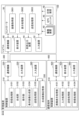
- the controller 30 includes, for example, an image acquisition unit 3001, a display processing unit 3002, and a transmission processing unit 3003 as functional units realized by executing one or more programs installed in the auxiliary storage device on the CPU. I have.
- a part of the functions of the controller 30 may be realized by another controller. That is, the functions of the controller 30 may be distributed and implemented by a plurality of controllers.
- peripheral imaging application a predetermined application program
- the peripheral imaging application is an application used to display captured image data captured by the imaging device 40 provided on the shovel 100 and to transmit the captured image data to the management device 300 .
- the image acquisition unit 3001 acquires captured image data around the excavator 100 captured by the four imaging devices 40 .
- the image acquisition unit 3001 acquires captured image data around the excavator 100 captured by each of the four imaging devices 40 each time the excavator 100 moves a predetermined distance or at predetermined time intervals. get.
- the display processing unit 3002 processes the captured image data acquired by the image acquisition unit 3001 so as to be displayed on the display device 50 .
- the transmission processing unit 3003 includes captured image data around the excavator 100 captured by each of the four imaging devices 40 using the communication device 60 and various information associated with the captured image data. Information (hereinafter referred to as transmission data) is transmitted to the management device 300 . Various information will be described later.
- the transmission processing unit 3003 may switch whether to transmit according to the acquired information. For example, when the controller 30 determines that the tilt of the excavator 100 is greater than or equal to a predetermined angle based on an acceleration sensor or the like provided on the excavator 100, the transmission processing unit 3003 may suppress transmission of the transmission data. As a result, it is possible to suppress the display of the captured image data when the excavator 100 runs over earth and sand, so that the visibility can be improved.
- FIG. 5 is a diagram exemplifying transmission data 5005 including captured image data transmitted by the transmission processing unit 3003.
- the transmission processing unit 3003 generates captured image data 5001 captured by the imaging device 40F, captured image data 5002 captured by the imaging device 40R, and captured image data captured by the imaging device 40L.
- 5003 and captured image data 5004 captured by the imaging device 40B are combined into one.
- Various types of information in the transmission data 5005 include the current position coordinates (latitude and longitude) measured by the GPS unit 46, the direction of the excavator 100 (direction in which the excavator 100 is facing), and the image capturing time acquired by the timing device 48.
- the indicated date and time information (including the time) is included.
- the various information may include information indicating the amount of movement of the excavator 100, the amount of turning of the excavator 100, and the like after the previous transmission data 5005 was transmitted.
- 5004 may be included.
- the various information of the transmission data 5005 may include information input by the operator from the input device 340 .
- the information input by the operator may include, for example, information indicating the work process related to the work currently being performed by the excavator 100 .
- the captured image data displayed on the display device 50 may be included. Accordingly, by referring to the various information, the screen displayed on the display device 50 of the excavator 100 can be grasped. For example, when displaying a screen showing the surroundings of the excavator 100 at a predetermined time, the screen displayed on the display device 50 at that time can be displayed. Thereby, the screen displayed on the display device 50 can be compared with the situation around the excavator 100 when the screen is displayed.
- the various information of the transmission data 5005 may include information indicating the inclination of the excavator 100 when the excavator 100 is provided with an acceleration sensor or the like.
- various information of the transmission data 5005 includes, for example, when the excavator 100 is aware of the work process for reasons such as civil engineering work using ICT (Information and Communication Technology), the current excavator Information indicating the steps 100 are performing may also be included.
- various types of information according to the present embodiment include at least the current position coordinates, the orientation of the excavator 100, and the date and time information indicating the time of imaging acquired by the timing device 48.
- the various types of information are not limited to a form that includes all of the position coordinates, the orientation of the excavator 100, and date and time information. At least one of them should be included.
- the management device 300 may specify the position coordinates of the excavator 100 based on the date and time information. More specifically, when the management device 300 recognizes the movement trajectory of the excavator 100 according to the time, even if the position coordinates are not included in the various data, the captured image data can be retrieved based on the date and time information. It is possible to specify the position coordinates of the captured image. Further, when the excavator 100 has passed through a predetermined position coordinate multiple times, the transmission processing unit 3003 transmits a plurality of captured image data having different date and time information at the position coordinate. Thereby, the management device 300 can manage a plurality of captured image data corresponding to the same position coordinates.
- the four imaging devices 40 fixed to the excavator 100 simultaneously perform imaging. Therefore, imaged image data in four directions is transmitted for each imaged position coordinate and date/time information.
- imaged image data in four directions is transmitted for each imaged position coordinate and date/time information.
- the method is not limited to transmitting captured image data in all four directions. For example, when the excavator 100 is present on a passage, the excavator 100 may acquire and transmit only captured image data in directions in which the excavator 100 can move on the passage.
- the transmission processing unit 3003 transmits the transmission data 5005 including the various information described above to the management device 300 . Accordingly, the management device 300 can manage the situation of the work site together with the information indicating the current situation of the excavator 100 . Next, the position where the excavator 100 performs imaging will be described.
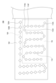
- FIG. 6 is a diagram showing positions at which the excavator 100 according to the present embodiment performs imaging.
- two excavators first excavator 100A and second excavator 100B
- the working area is divided for each excavator.
- the first excavator 100A works in a work area 701 (area surrounded by dashed lines)
- the second excavator 100B works in a work area 702 (area outside the area surrounded by dashed lines). I do.
- the first excavator 100A and the second excavator 100B capture an image using the imaging device 40 each time they move a predetermined distance.
- the distance interval for imaging is determined according to the embodiment. Note that the timing at which the imaging device 40 takes an image is not limited to each time a predetermined distance is moved.
- each excavator 100 may travel in an assigned area regardless of the work, or while each excavator 100 is working in the work area assigned to it. may be imaged. By combining the imaging results of a plurality of excavators 100 working at the work site 700, it is possible to secure captured image data captured at each position of the entire work site.
- the first excavator 100A is moving along a movement trajectory 710 with a first position coordinate 710A as a starting point. Then, the imaging device 40 of the first excavator 100A takes an image at the position indicated by the circle mark "O" each time the first excavator 100A moves a predetermined distance.
- the second excavator 100B moves along the movement trajectory 720 with the first position coordinates 720A as the starting point. Then, the imaging device 40 of the second excavator 100B captures an image of each marker indicated by a square mark " ⁇ " each time the second excavator 100B moves a predetermined distance.
- the transmission processing unit 3003 of the first excavator 100A and the second excavator 100B transmits the transmission data 5005 corresponding to each imaged position to the management device 300.
- the management device 300 can receive captured image data of the entire area of the work site 700 even when the work area is shared between the first excavator 100A and the second excavator 100B.
- the communication terminal 400 which will be described later, can grasp the situation of the work site based on the captured image data regardless of which of the first excavator 100A and the second excavator 100B captured the image. Note that the correspondence relationship between the position where the image was captured and the screen to be displayed will be described later.
- the management device 300 can receive a plurality of captured image data captured at substantially the same position at different times. Therefore, the management device 300 can store changes in the work site over time at substantially the same position.
- the management device 300 includes a control device 310 , a communication device 320 , an output device 330 and an input device 340 .
- the communication device 320 is any device that communicates with external devices such as the excavator 100 and the communication terminal 400 through the communication network NW.
- the output device 330 includes, for example, a display, and displays various information images under the control of the control device 310.
- the input device 340 receives various operational inputs by the operator of the management device 300 and outputs signals corresponding to the operational inputs to the control device 310 .
- the input device 340 can include, for example, a touch panel mounted on the display of the output device 330 that displays various information images, a keyboard, a mouse, and the like.
- the control device 310 controls various operations in the management device 300 .
- the control device 310 includes, for example, a reception processing unit 3101, a synthesis unit 3102, and a storage unit 3103 as functional units realized by executing one or more programs installed in a nonvolatile auxiliary storage device on the CPU. , a display image generation unit 3104 , and a transmission processing unit 3105 .
- the control device 310 also includes, for example, a composite image storage unit 350 as a storage area defined in a nonvolatile internal memory such as an auxiliary storage device.
- a storage area corresponding to the composite image storage unit 350 may be provided in an external storage device communicably connected to the control device 310 .
- the reception processing unit 3101 uses the communication device 320 to control reception of information from the communication terminal 400 or the excavator 100 .
- the reception processing unit 3101 controls reception of transmission data 5005 in which captured image data and various types of information are associated with each other from each of the first excavator 100A and the second excavator 100B.
- the reception processing unit 3101 receives transmission data 5005 including captured image data captured each time the excavator 100 moves a predetermined distance. Further, when the excavator 100 makes a round trip to and from the same place, the reception processing unit 3101 may repeatedly receive the transmission data 5005 including the captured image data captured at the same place in the same work site. In such a case, captured image data captured at different times at the same position are stored. As a result, changes in the vicinity of the excavator 100 according to changes in time can be saved.
- the transmission data 5005 (see FIG. 5) received by the reception processing unit 3101 includes data of four captured images captured in different directions by the excavator 100 and various information.
- the synthesizing unit 3102 synthesizes captured image data different in at least one of direction, time, and position included in the transmission data 5005 received by the reception processing unit 3101 . For example, four pieces of captured image data, which are included in the transmission data 5005 received by the reception processing unit 3101 and which are taken at the same position and at the same time and taken in different directions, are synthesized, and when the image is taken, the shovel Bird's-eye view image data representing the periphery of 100 is generated.
- the synthesizing unit 3102 may generate one synthetic image data from a plurality of pieces of transmission data 5005. For example, the synthesizing unit 3102 may synthesize a plurality of captured image data extracted from a plurality of transmission data 5005 captured at the same position at different times based on the captured position or orientation.
- the synthesizing unit 3102 may combine the captured image data at time A and the captured image data at time B, in which the obstacle is not captured, to synthesize bird's-eye view image data.
- bird's-eye view image data an example of composite image data
- the synthesizing unit 3102 can generate bird's-eye view image data with improved visibility by combining a plurality of captured image data.
- FIG. 7 is a diagram showing the concept of generating bird's-eye view image data by combining captured image data by the synthesizing unit 3102 according to this embodiment.
- the synthesizing unit 3102 generates captured image data in which obstacles are not captured in each of four directions centering on the position where the excavator 100 exists, among the captured image data captured by the imaging device 40. 1701 to 1704 are extracted, and the extracted captured image data 1701 to 1704 are synthesized to generate overhead image data 1705 .
- the storage unit 3103 saves the bird's-eye view image data synthesized by the synthesizing unit 3102 for each work site as various information included in the transmission data 5005, such as position coordinates (latitude and longitude), The direction in which the excavator 100 is facing, date information (including time), and information indicating the work process are associated with each other and stored in the composite image storage unit 350 .
- the synthesized bird's-eye view image data is stored in the synthesized image storage unit 350 each time the transmission data 5005 is transmitted.
- the storage unit 3103 stores overhead image data in the composite image storage unit 350 in association with various types of information.
- This embodiment is not limited to the method of storing the bird's-eye view image data after combining the four captured image data. good too.
- the synthesizing unit 3102 may synthesize overhead image data from the read captured image data, or the communication terminal 400 may synthesize the overhead image from the captured image data. You may
- the storage unit 3103 can associate and store bird's-eye view image data and various types of information for each position where the excavator 100 or the like is moving while the excavator 100 is operating.
- bird's-eye view image data and various types of information are associated and stored for each position indicated by a circle mark " ⁇ " and for each position indicated by a square mark " ⁇ ".
- the various information to be saved is the same as the various information stored as the transmission data 5005 described above, so description thereof will be omitted.
- the storage unit 3103 stores the above-described information in the composite image storage unit 350 for each work site. At that time, the storage unit 3103 also stores information indicating the location (for example, address and latitude/longitude) and name of the work site in the composite image storage unit 350 . This allows the user to select the worksite that they wish to view.
- the display image generation unit 3104 generates display image data for display on the communication terminal 400 from the overhead image data stored in the composite image storage unit 350 .
- the generated display image data is image data displayed as if the work site was viewed from the viewpoint of the excavator 100, a person, or the like.
- the display image generation unit 3104 generates virtual three-dimensional space data representing the work site by projecting the bird's-eye view image data onto a virtual three-dimensional space model.
- the three-dimensional space model may be, for example, a cylindrical shape.
- a virtual three-dimensional space centered on the excavator 100 can be realized by projecting the bird's-eye view image data onto the cylindrical side and bottom surfaces.
- the display image generation unit 3104 sets the position where the excavator 100 existed in the virtual three-dimensional space indicated by the three-dimensional space data as the viewpoint, and the line of sight (the direction viewed by the eyes) is set in a predetermined direction. ) and reprojected onto a two-dimensional virtual plane.
- the display image generation unit 3104 projects the tilt of the excavator 100 onto the virtual three-dimensional model. After that, display image data as if the work site is viewed from an arbitrary viewpoint may be generated. This allows the user who is referring to the display image to recognize the situation including the inclination of the work site.
- display image data may be generated from captured image data, or captured image data may may be used as
- the transmission processing unit 3105 uses the communication device 320 to control transmission of information to the communication terminal 400 or the excavator 100 .
- the transmission processing unit 3105 transmits the display image data (an example of the synthesized image) generated by the display image generation unit 3104 to the communication terminal 400 .
- the transmission processing unit 3105 if the reception processing unit 3101 receives a request to transmit display image data from the communication terminal 400 with at least one of direction, time period or time, and position specified, the transmission processing unit 3105 , according to the designation, display image data generated based on at least one of the designated direction, time period or time, and position is transmitted to the communication terminal 400 .
- the case of transmitting the display image data to the communication terminal 400 has been described as an example of control for displaying the display image data as if the work site was viewed from an arbitrary viewpoint.
- the control for displaying the display image data is not limited to transmission of the display image data to communication terminal 400, and may be display control of the display image data.
- the communication terminal 400 can display the display image data as if the excavator 100 were looking in a predetermined direction from the position where the image was taken.
- the display image data has a narrower angle of view than the bird's-eye view image data, but represents the situation of the excavator 100 at an angle of view close to the human viewing angle. Since such display image data can be displayed, the user of the communication terminal 400 can understand the surroundings of the excavator 100 without any discomfort.
- the data transmitted by the transmission processing unit 3105 is not limited to display image data as if the work site was viewed from an arbitrary viewpoint.
- Image data, or image data of four images, or the like may be used.
- the user of communication terminal 400 can visually recognize the work site in a desired manner, thereby facilitating understanding of the situation of the work site.
- the communication terminal 400 may generate and display display image data as if the work site was viewed from an arbitrary viewpoint from the overhead image data, or may display the overhead image data as it is. may be displayed.
- FIG. 8 is a diagram showing an example of bird's-eye view image data generated by the synthesizing unit 3102 of the management device 300 according to this embodiment.
- the bird's-eye view image data shown in FIG. 8 is an image generated based on the four imaging devices 40 provided on the excavator 100, and is an image of the excavator 100 viewed from a viewpoint a predetermined distance above the excavator 100. represents the surroundings.
- the bird's-eye view image data represents the 360-degree surroundings of the excavator 100 .
- the bird's-eye view image data indicates equidistant lines EQL centered on the icon TCG representing the excavator 100 .
- the bird's-eye view image data includes not only objects existing near the excavator 100 but also objects existing horizontally distant from the excavator 100 (for example, a mountain 601 and a chimney 602).
- the bird's-eye view image data onto a virtual three-dimensional space model, it is possible to generate display image data representing the surroundings of the excavator 100 from an arbitrary viewpoint existing in the three-dimensional space. That is, in the present embodiment, as described above, it is possible to generate and display a screen of a work site viewed from an arbitrary viewpoint using bird's-eye view image data.
- the image data used to display the screen of the work site viewed from an arbitrary viewpoint is not limited to bird's-eye view image data. Alternatively, other types of image data may be used.
- Communication terminal 400 includes control device 410 , communication device 420 , display device 430 , and input device 440 .
- the communication device 420 is any device that communicates with an external device such as the management device 300 through the communication network NW.
- the communication device 420 is, for example, a mobile communication module compatible with mobile communication standards such as LTE, 4G, and 5G.
- the display device 430 displays various information images.
- the display device 430 is, for example, a liquid crystal display or an organic EL display.
- the input device 440 is an example of an operation unit that receives various operations on the communication terminal 400 from the user.
- the input device 440 includes, for example, a hardware operation unit such as buttons and a touch panel mounted on the display device 430 . Further, the input device 440 may be a combination of a hardware operation unit such as a touch panel mounted on the display device 430 and a software operation unit such as button icons on the operation screen displayed on the display device 430 .
- the control device 410 controls various operations of the communication terminal 400 .
- the control device 410 includes, for example, an image display processing unit 4101, an input processing unit 4102, and a transmission processing unit as functional units realized by executing one or more programs installed in a nonvolatile auxiliary storage device or the like. 4103 and a reception processing unit 4104 are realized.
- Functions such as the image display processing unit 4101, the input processing unit 4102, the transmission processing unit 4103, and the reception processing unit 4104 are performed by a predetermined application program installed in the control device 410 according to a predetermined operation on the input device 440 by the user. (hereinafter referred to as "site display application”) may be enabled by starting.
- the site display application is an application used to display display image data representing the situation of the work site from an arbitrary viewpoint based on the captured image data captured by the imaging device 40 of the excavator 100 .
- a work site list screen is displayed when the site display application is started.
- the image display processing unit 4101 performs processing for displaying a screen related to the on-site display application on the display device 430 .
- the image display processing unit 4101 displays a work site list screen. The user can select a work site to be displayed and specify a position to be displayed within the work site from the work site list screen.
- the input processing unit 4102 performs input processing corresponding to various user operations on the screen related to the on-site display application via the input device 440 .
- the input processing unit 4102 inputs the selected work site and the designated position.
- Information to be input and processed by the input processing unit 4102 is not limited to the combination of the selected work site and the designated position.
- the information to be input and processed may be only the work site, or may include at least one of position, time, and direction when the work site is specified.
- the transmission processing unit 4103 uses the communication device 420 to transmit information to the management device 300 .
- the transmission processing unit 4103 manages a request to transmit information regarding the work site and the designated position. Send to device 300 .
- the transmission processing unit 4103 transmits to the management device 300 a transmission request (for example, at least one of position, time, and direction) based on the information input and processed by the input processing unit 4102 .
- the reception processing unit 4104 uses the communication device 420 to receive and process information from the management device 300 .
- the reception processing unit 4104 receives and processes display image data representing the situation of the work site as seen from a specified position on the work site.
- the image display processing unit 4101 displays the display image data received by the reception processing unit 4104.
- the communication terminal 400 an example of an information processing device
- displays display image data representing the situation of the work site as viewed from a specified position will be described. It is also possible to display bird's-eye view image data instead of objects, or to display captured image data itself. In other words, any display related to captured image data captured by the excavator 100 may be used.
- the input processing unit 4102 can specify the work site (the position of the excavator 100 captured, the direction to be displayed, and the time zone). is received, the transmission processing unit 4103 transmits a transmission request to the management device 300 together with the designation.
- the reception processing unit 4104 receives display image data associated with at least one of the direction, time, and position specified by the user from the management device 300 .
- the image display processing unit 4101 displays the received display image data. This makes it easier to grasp the situation of the work site according to the user's designation.
- FIG. 9 is a diagram showing a work site list screen displayed by the image display processing unit 4101 according to the present embodiment.
- FIG. 9 shows a work site field 1301, a map display field 1302, and a display start button 1303.
- the work site column 1301 shows a list of selectable work site addresses and names. The information on the address and name of each work site is assumed to be information received in advance from the management device 300 . The user selects a work site to be displayed from the work site column 1301 .
- map data is displayed in the map display field 1302.
- the map data to be displayed is not limited to map data within the work site, and map data of a wider range (for example, map data within Japan) may be displayed.
- the map data displayed in the map display field 1302 may be enlarged or reduced according to the user's operation.
- the image display processing unit 4101 displays an icon (for example, the icon 1313) indicating the presence of a work site on the map data (for example, map data in Japan) according to the location (address or latitude/longitude) of the work site. do.
- the input processing unit 4102 receives selection of the icon 1313, in other words, selection of the work site. When the selection of the icon 1313 is received, the position and name of the work site corresponding to the icon 1313 may be automatically selected in the work site column 1301 .
- the transmission processing unit 4103 requests transmission of information on the work site together with information indicating the selected work site (for example, position and name). , to the management device 300 .
- the management device 300 designates the position, direction, and time period in which the image was captured based on the initial settings in the work site, and responds to the designation. Display image data is generated and transmitted to communication terminal 400 .
- the communication terminal 400 receives the display image data representing the work site viewed from an arbitrary viewpoint from the management device 300, and displays the received display image data.
- the user can confirm the status of the work site as if he or she were actually looking at the display based on the captured image data captured by the excavator 100 present at the work site. becomes.
- map display column 1302 is not limited to displaying the map data described above, and may display map data of the work site selected in the work site column 1301 .
- FIG. 10 is a diagram showing a work site list screen displayed by the image display processing unit 4101 according to the present embodiment.
- the map data corresponding to the work site selected in the work site column 1301 is displayed in the map display column 1302.
- a black circle (for example, reference numeral 1311) shown in the map display field 1302 indicates the position where the image was taken.
- the user can specify a black circle to be displayed from the black circles displayed in the map data displayed in the map display field 1302 .
- the specified black circle is switched to a white circle (for example, white circle 1312).
- the input processing unit 4102 accepts designation of the position indicated by the white circle 1312 .
- the transmission processing unit 4103 transmits to the management apparatus 300 a transmission request for information regarding the selected work site and the designated position. Subsequent processes are the same, and descriptions thereof are omitted.
- communication terminal 400 can display the display image data corresponding to the position specified by the user. Then, the user can recognize the situation around the designated position.
- this embodiment shows an example of a list screen of work sites, and settings related to the work sites to be displayed may be designated by another method.
- a field for making the designation may be added to the work site list screen.
- the list screen may display a field for accepting input of date and time and a field for accepting direction.
- the user may specify the time zone (including date and time) that they want to display.
- the transmission processing unit 4103 manages the transmission request for information regarding the selected work site and the designated time period. Send to device 300 . Thereby, the user can recognize the display image data captured at the work site during the specified time period.
- This embodiment shows an example of a screen for selecting a work site, and other modes may be used.
- communication terminal 400 may display a text box on the search screen, display a list of work sites that match the character string input in the text box, and accept selection of a work site from the list.
- FIG. 11 is a diagram exemplifying a display screen displayed by the image display processing unit 4101. As shown in FIG. On the display screen shown in FIG. 11, display image data 800 is displayed as if the work site was viewed from an arbitrary viewpoint. A bar (an example of operation information) is displayed.
- this embodiment does not limit the setting of the time period to operations on the bar. For example, you may input a time zone with a character. Furthermore, specific dates and times, for example, “4 days ago (1 day)”, “7 days ago (1 day)”, “13:30 on the 12th”, “latest”, etc. can be accepted. good.
- the user can switch the time zone (including the time) of the work site to be displayed by operating.
- the transmission processing unit 4103 transmits to the management device 300 a transmission request for the display image data captured at the same position and within the changed time period.
- the reception processing unit 4104 receives the display image data corresponding to the changed time zone at the same position.
- the image display processing unit 4101 displays the display image data showing the situation in the designated time period.
- the time to be displayed can be switched according to the user's operation, so the user can recognize the situation at the work site during the specified time period. For example, the user can easily check the situation of the work site at night, the situation of the work site at sunset, the situation of the work site during the day, or the like. Then, the user can perform various operations on the display screen shown in FIG. For example, the user can switch the viewing direction. Although any method may be used as a method for switching the viewing direction, for example, the following method is conceivable.
- the input processing unit 4102 receives pressing of the area 822 or area 821 .
- the transmission processing unit 4103 transmits to the management device 300 a transmission request for the display image data in the same position and in the direction (leftward or rightward) corresponding to the pressed area 822 or 821 .
- the reception processing unit 4104 receives the display image data corresponding to the pressed direction at the same position.
- the image display processing unit 4101 displays the display image data whose orientation is switched by 90 degrees.
- the orientation switching may be performed in angular increments other than 90 degrees, such as 30 degrees or 45 degrees. In this manner, since the direction to be displayed can be switched according to the user's operation, confirmation of the situation at the work site is facilitated.
- the user can switch the displayed viewpoint as if moving within the virtual space.
- an icon 801 (an example of display information) for switching the viewpoint to another position is displayed on the display image data shown in FIG.
- An icon 801 displayed in the display image data corresponds to the position where the excavator 100 has taken the image.
- an icon is added to the position where the excavator 100 captured the image.
- the display image data shown in FIG. 11 is the display image data showing the situation of the work site from the position coordinates 710G shown in FIG.
- An icon 801 indicating "o" is displayed.
- the transmission processing unit 4103 requests display image data as if the work site was viewed from the position indicated by the icon 801. 300.
- the communication terminal 400 can receive and display display image data based on the captured image data captured at the position corresponding to the icon 801 (as if the work site is viewed from that position). .
- the display image data according to the present embodiment icons that can be pressed are displayed so as to correspond to the position where the first excavator 100A was present.
- the image display processing unit 4101 switches the display to the display image data corresponding to the position where the image was captured.
- the user can switch the display of the display image data according to the moving route of the first excavator 100A by pressing the icon attached to the display image data.
- the surrounding image management system SYS it is possible to realize an image display (walk-through) in which the viewpoint changes as if the user were moving within the image.
- the peripheral image management system SYS according to this embodiment can improve the operability.
- the conditions for displaying the icon are that the image is captured at the position indicated by the icon and that the time at which the image was captured is included in the time period set by the user. . For example, when one week is set as the time period, an icon indicating the position is displayed at the position where the image was captured during the one week. Thereby, it is possible to switch the display between the display image data captured within the time zone specified by the user.
- the icon for changing the viewpoint displayed in the display image data is not limited to a form indicating a movable position such as "o".
- it may be an icon or the like that indicates the movable direction in the shape of an arrow or the like.
- the present embodiment is not limited to the method of displaying icons for switching viewpoints in the virtual space, and other methods (for example, guidance of movable positions using characters, etc.) may be used.
- the icons for changing the viewpoint are not limited to those displayed according to the moving route of the shovel 100.
- an icon for changing to the viewpoint may be displayed at a position where the management device 300 holds the bird's-eye view image data.
- the communication terminal 400 displays the display image data related to the position imaged by the first excavator 100A
- the position imaged by the second excavator 100B exists in the vicinity of the position.
- the display image data can be switched to the position where the image was captured by the second excavator 100B.
- FIG. 12 is a diagram exemplifying a display screen displayed by the image display processing unit 4101.
- FIG. 12 also displays a bar for setting the time zone (an example of information about time) as in FIG. 11, the description thereof is omitted.
- an icon 901 for switching the viewpoint to another position is displayed on the display image data 900 displayed on the display screen.
- the icon 901 is given to the display image data 900 when the display image generation unit 3104 of the management device 300 generates the display image data 900 .
- the icon “ ⁇ ” indicating the position where the first excavator 100A captured the image and the icon “ ⁇ ” indicating the position where the second excavator 100B captured the image are displayed separately.
- the icons displayed on the screen differ in display mode according to the shovel 100 imaged from the position indicated by the icon.
- the display image data shown in FIG. 12 is display image data showing the surrounding situation from the position coordinate 710G (imaged by the first excavator 100A) shown in FIG.
- an icon 901 (an example of display information) showing a square mark " ⁇ " is added to the position corresponding to the position coordinate 720B where the second excavator 100B has taken the image.
- the transmission processing unit 4103 sends a request for display image data as if the work site was viewed from the position indicated by the icon 901. 300. Accordingly, the communication terminal 400 can receive and display the display image data with the position corresponding to the icon 901 as the viewpoint.
- the display is switched according to the moving route of each excavator 100. Not only that, it is also possible to switch the display between different excavators 100 .
- FIG. 13 is a sequence diagram showing a processing procedure up to storage of composite image data in the peripheral image management system SYS according to this embodiment.
- the excavator 100 moves at the work site (S1001). Then, the controller 30 of the excavator 100 determines whether or not the excavator 100 has moved a predetermined distance from the inputs of various sensors (S1002). When determining that the controller 30 has not moved the predetermined distance (S1002: No), the process is performed again from S1001.
- the image acquisition unit 3001 acquires image data captured by the image capturing device 40 after the image capturing process by the image capturing device 40 (S1003). .
- the GPS unit 46 outputs the current position and direction to the controller 30 (S1004).
- the transmission processing unit 3003 puts together the acquired captured image data, and then transmits transmission data 5005 including various information such as current position information, direction information, and information on the date and time when the image was captured to the management apparatus 300. (S1005). Note that the position information and the direction information may not be included in the various information if the measurement fails.
- the controller 30 of the excavator 100 determines whether or not the movement has ended (S1006). If the movement has not ended (S1006: No), the process is repeated from S1001.
- the reception processing unit 3101 of the management device 300 determines whether or not the transmission data 5005 including captured image data and the like has been received from the excavator 100 (S1011). If the transmission data 5005 has not been received (S1011: No), the process is repeated until it is received.
- the synthesis unit 3102 determines whether the transmission data 5005 includes position information and direction information. (S1012). If it is determined that it is included (S1012: Yes), the process proceeds to S1014.
- the synthesizing unit 3102 determines that the transmission data 5005 does not include at least one of the position information and the direction information (S1012: No), based on the captured image data included in the transmission data 5005, the synthesizing unit 3102 Then, the position and direction where the captured image data was captured are calculated (S1013). For example, the synthesizing unit 3102 extracts feature information ( For example, based on how much the positions of the mountains 601 and chimneys 602 are displaced, the position and direction where the imaging device 40 captured the captured image data are calculated. Further, the synthesizing unit 3102 may calculate the position and direction based on the amount of movement and the amount of turning included in the various information.
- the synthesizing unit 3102 synthesizes the four captured image data to generate bird's-eye view image data (S1014).
- the storage unit 3103 associates the generated bird's-eye view image data with position information (for example, latitude and longitude), direction information (the direction in which the excavator 100 is facing), and date/time information (including time).
- position information for example, latitude and longitude
- direction information the direction in which the excavator 100 is facing
- date/time information including time.
- the image is stored in the composite image storage unit 350 (S1015). If the transmission data 5005 includes information such as the work process, the information such as the work process is also stored in the composite image storage unit 350 . After saving, the management device 300 performs the processing from S1011 again.
- the bird's-eye view image data and various information are associated with each other by the above-described processing procedure and stored in the composite image storage unit 350 .
- the work site can be displayed on communication terminal 400 .
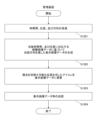
- FIG. 14 is a flow chart showing a processing procedure for displaying display image data showing a work site on the communication terminal 400 according to this embodiment.
- the site display application is started (S1101). As a result, a work site list screen (see FIG. 9) is displayed.
- the input processing unit 4102 of the site display application receives the settings of the work site and the position of the work site from the work site list screen (S1102). Acceptance of setting the location of the work site is optional.
- the transmission processing unit 4103 transmits to the management device 300 a transmission request for the display image data together with the designated work site and the location of the work site (S1103). If the setting of the position of the work site is not accepted, only the information identifying the work site is transmitted together with the transmission request.
- the reception processing unit 4104 receives from the management device 300 the display image data, etc., showing the work site viewed from the transmitted position (S1104).
- the display image data received by the reception processing unit 4104 is given an icon (an example of display information) indicating the position where the image was captured.
- the received display image data is image data that satisfies the conditions transmitted together with the transmission request in S1103. It is assumed that the line-of-sight direction of the received display image data and the time period during which the image was captured are set in advance as initial settings.
- the image display processing unit 4101 displays the received display image data and the icon attached to the display image data (S1105).
- the input processing unit 4102 determines whether or not a direction change has been received by pressing a predetermined area in the display image data (S1106). If the direction change has been accepted (S1106: Yes), the transmission processing unit 4103 sends the changed direction, the same position as the currently displayed position, and the time period set in the current bar (an example of information related to time). ) and a request for transmission of display image data to the management device 300 (S1107). After that, in S1104, the display image data satisfying the sent condition is received.
- the input processing unit 4102 determines whether or not pressing of the icon added to the display image data has been received (S1108).
- the transmission processing unit 4103 displays the position indicated by the pressed icon, the same direction as the currently displayed direction, and the time period set in the bar.
- An image data transmission request is transmitted to the management device 300 (S1109).
- the position indicated by the icon is the actual position of the work site indicated by the icon, which is indicated by latitude and longitude, for example. Information on the position is stored in advance as, for example, attribute information of the display image data. After that, in S1104, the display image data satisfying the sent condition is received.
- the input processing unit 4102 determines whether or not it has accepted the change of the time zone (S1110).
- the transmission processing unit 4103 displays the display image together with the changed time period, the same position as the currently displayed position, and the same direction as the currently displayed direction.
- a data transmission request is transmitted to the management device 300 (S1111). After that, in S1104, the display image data satisfying the sent condition is received.
- the control device 410 determines whether or not the operation has ended (S1112). If the operation has not ended (S1111: No), the process is repeated from S1106.
- control device 410 determines that the operation has ended (S1112: Yes), it ends the process.
- the communication terminal 400 according to the present embodiment can display the display image data according to the user's request by the above-described processing procedure.
- FIG. 15 is a flowchart showing a processing procedure up to transmission of display image data in the management device 300 according to this embodiment.
- the reception processing unit 3101 receives, from the communication terminal 400, a transmission request for display image data together with at least one of the position, direction, and time period (an example of information regarding time) indicating the work site to be displayed. (S1201). Note that the reception processing unit 3101 does not have to receive all of the position, direction, and time period together with the transmission request. For example, the reception processing unit 3101 may receive only information identifying the work site from the communication terminal 400 . Information not received (for example, location, time zone and direction of photographing) is determined according to the initial settings.
- the display image generation unit 3104 identifies the bird's-eye view image data corresponding to the time zone and the position, reads the bird's-eye view image data from the synthesized image storage unit 350, and views the work site from the position in the direction. (S1202). Note that if there are a plurality of bird's-eye view image data included in the time period, the latest bird's-eye view image data is read.
- the display image generation unit 3104 adds an icon to the generated display image data at the position coordinates corresponding to the position where the bird's-eye view image data is stored in the synthesized image storage unit 350 (the position where the viewpoint can be switched). It is applied (superimposed) (S1203).
- the transmission processing unit 3105 transmits the display image data (an example of information based on the composite image data) to the communication terminal 400 (S1204).
- the display image data includes, as attribute data, information on the position of the work site corresponding to the position indicated by the icon.
- the management device 300 can transmit display image data in response to a request from the communication terminal 400 by the above-described processing procedure.
- Modification 1 the method of displaying the display image data as if the work site was viewed from an arbitrary viewpoint by the image display processing unit 4101 of the communication terminal 400 was specifically described.
- the display data displayed by the communication terminal 400 is not limited to the display image data representing the work site viewed from an arbitrary viewpoint.
- map data of the work site may be displayed. Therefore, in the modified example, an example of displaying map data of a work site will be described.
- the management device 300 when the management device 300 receives a request to display the map data of the work site from the communication terminal 400, it generates the map data.
- the synthesizing unit 3102 synthesizes captured image data captured in the same position by the excavator 100 and in different directions to generate bird's-eye view image data.
- Site bird's-eye view image data representing a work site in a bird's-eye view is generated by cutting out predetermined areas from the bird's-eye view image data and connecting them.
- the synthesizing unit 3102 generates bird's-eye view image data of the entire work site using bird's-eye view image data generated based on captured image data captured within a predetermined time period.
- the bird's-eye view image data of the entire work site is image data that represents an area within the work site in a bird's-eye view like an aerial photograph.
- the excavator 100 generates bird's-eye view image data of the entire work site based on captured image data captured during movement caused by work.
- the storage unit 3103 may store the generated bird's-eye view image data of the entire work site in the composite image storage unit 350 .
- the management device 300 transmits the bird's-eye view image data of the entire work site generated by the synthesizing unit 3102 to the communication terminal 400 .
- a screen showing a bird's-eye view of the work site can be displayed on the communication terminal 400 (for example, bird's-eye view image data of the entire work site can be displayed).
- the user can easily check the state of the entire area where the excavator 100 has worked.
- the synthesizing unit 3102 stores the bird's-eye view image data of the entire work site stored in the synthetic image storage unit 350 . Based on, the enlarged or reduced bird's-eye view image data of the entire work site is generated. Then, the transmission processing unit 3105 transmits the generated bird's-eye view image data of the entire work site to the communication terminal 400, thereby realizing a display that meets the user's request.
- Modification 2 In the modified example 1, an example of displaying the generated bird's-eye view image data of the entire work site has been described.
- the present invention is not limited to displaying only the generated bird's-eye view image data of the entire work site, and the bird's-eye view image data of the entire work site may be superimposed and displayed on the corresponding area of the actual map data.
- position coordinates for example, latitude and longitude
- the map data may be, for example, image data showing conditions such as domestic roads and sites, or may be an aerial photograph showing a bird's-eye view of the country.
- the reception processing unit 4104 of the communication terminal 400 receives bird's-eye view image data of the entire predetermined work site from the management device 300 when displaying the work site list screen, and also receives map data including the surroundings of the work site. to get
- the acquisition source of the map data is, for example, the map providing service or the management device 300 .
- the map data acquisition method is not limited, and may be stored in advance in the storage unit of communication terminal 400 .
- the image display processing unit 4101 of the communication terminal 400 displays the bird's-eye view image data of the entire work site based on the acquired position coordinates of the bird's-eye view image data of the entire work site and the position coordinates embedded in the map data. , superimposed on the corresponding area of the map data. Note that the process of superimposing the bird's-eye view image data of the entire work site on the corresponding area of the map data is not limited to the example performed by the communication terminal 400 and may be performed by the management device 300 .
- the user can confirm both the specific situation inside the work site and the situation around the work site.
- the transmission data 5005 may include at least one of position coordinates, orientation of the excavator 100, and date/time information (including time) as various information.
- Modified Example 3 an example in which the transmission data 5005 includes one of position coordinates, orientation of the excavator 100, and date/time information (including time) as various data will be described.
- the management device 300 when only position coordinates are included as various information in the transmission data 5005, the management device 300 according to the modification manages the four captured image data in association with the position coordinates. Accordingly, when the specification of the position coordinates is received from the communication terminal 400 , the four captured image data associated with the position coordinates may be transmitted to the communication terminal 400 .
- the management device 300 may manage each piece of captured image data in association with information indicating which imaging device 40 captured the image.
- the four pieces of imaged image data associated with the positional coordinates are converted into the four pieces of imaged image data in consideration of the image pickup device 40 that took the image. may be transmitted to the communication terminal 400, or the bird's-eye view image data obtained by synthesizing the captured image data of the four images may be transmitted.
- the communication terminal 400 can check the surroundings of approximately 360 degrees of the position information. Even if the four captured image data are not associated with the direction, the user who is aware of the work site can refer to the four captured images displayed on the communication terminal 400. understand the situation at the work site. Note that if the information of the direction is included in the various information of the transmission data 5005 in addition to the positional coordinates, it is possible to display the image taking into consideration the direction in which the image was taken, which makes it easier to understand the work site.
- the management device 300 when only the direction is included as various information in the transmission data 5005, the management device 300 according to the modification manages the four captured image data in association with the direction in which the excavator 100 is facing. Alternatively, the management device 300 manages each piece of captured image data in association with the photographed direction (the direction in the world coordinate system). Furthermore, the management device 300 may manage each of the four captured image data in association with information indicating which image capturing device 40 captured the image. Further, the management device 300 may manage each piece of captured image data in association with the direction in which the captured image data was captured.
- a direction (azimuth) designation is received from the communication terminal 400 , captured image data obtained by capturing the direction (azimuth) may be transmitted to the communication terminal 400 . Communication terminal 400 may display a list of captured images corresponding to the direction (orientation) based on the received captured image data.
- the management device 300 When the transmission data 5005 includes, for example, only time information (time of image capture) as the various information, the management device 300 according to the modification manages the four captured image data in association with the time of image capture. . Furthermore, the management device 300 may manage each of the four captured image data in association with information indicating which image capturing device 40 captured the image.
- a list of captured image data captured at that time may be transmitted to communication terminal 400 .
- Communication terminal 400 may display a list of captured images corresponding to time. This allows the user to recognize the situation of the entire work site at that time.
- Modification 4 In the above-described embodiment and modified example, an example has been described in which the management device 300 generates display image data representing a work site viewed from an arbitrary viewpoint. However, the above-described embodiments are not limited to the method in which the management device 300 generates the display image data representing the work site as if viewed from an arbitrary viewpoint. In Modified Example 3, a case where display image data is generated by communication terminal 400 will be described.
- the synthesizing unit 3102 of the management device 300 generates bird's-eye view image data based on the captured image data transmitted from the excavator 100 . Then, the transmission processing unit 3105 of the management device 300 transmits the overhead image data to the communication terminal 400 . When transmitting the bird's-eye view image data, the transmission processing unit 3105 also transmits position coordinate information for adding an icon.
- the image display processing unit 4101 of the control device 410 of the communication terminal 400 projects the received bird's-eye view image data onto a virtual three-dimensional space model, then re-projects onto a two-dimensional virtual plane, and displays the data. Generate image data.
- the method of generating the display image data is the same as in the above-described embodiment, and the description thereof is omitted.
- the image display processing unit 4101 displays the generated display image data on the display device 430 .
- an icon is added to the display image data in the same manner as in the above-described embodiment.
- the image display processing unit 4101 displays the display image data with the icon added. Then, when the input processing unit 4102 receives an operation to change the display direction, the image display processing unit 4101 converts the display image data whose display direction is changed based on the received bird's-eye view image data. Generate.
- the image display processing unit 4101 displays the received bird's-eye view image data.
- the image display processing unit 4101 when the input processing unit 4102 receives an operation to enlarge a portion of the display image data, the image display processing unit 4101 generates a display image in which the partial area is enlarged based on the bird's-eye view image data. Generate and display data.
- the display image data is generated by the communication terminal 400, so compared to the case where the display image data is received from the management device 300, the network load can be reduced and the response time based on transmission/reception can be shortened. .
- the transmission processing unit 4103 transmits to the management device 300 a transmission request for bird's-eye view image data corresponding to the position.
- communication terminal 400 can receive the bird's-eye view image data corresponding to the position.
- Modification 5 Furthermore, in the above-described embodiment and modification, an example in which the management device 300 generates overhead image data has been described, but the communication terminal 400 (an example of an information processing device) may generate overhead image data. good.
- the management device 300 associates the various information transmitted from the excavator 100 with the four captured image data and stores them in the storage unit.
- the management device receives a transmission request for captured image data and conditions (for example, position and time period) of the captured image data to be transmitted from the communication terminal 400, the management device selects four captured images that match the conditions. Data is transmitted to communication terminal 400 .
- the image display processing unit 4101 of the communication terminal 400 generates bird's-eye view image data from the received four captured image data. Subsequent processing is the same as that of Modification 1, and description thereof is omitted.
- At least one of the direction, time, and position at the construction site is specified in the communication terminal 400, so that the Display (for example, display of display image data) is realized. This makes it easier to grasp the situation of the work site around the excavator 100 .
- peripheral image management system SYS by manipulating the display image data displayed on the communication terminal 400, if the excavator 100 has moved, it will appear as if it were moving. Switching of display image data can be realized. As a result, it becomes easier to grasp the situation of the work site, and the operation for grasping the situation of the work site becomes easier.
- the peripheral image management system SYS it is possible to display the situation of the work site in the time zone (an example of information related to time) specified by the user. This makes it possible to check the changes in the situation of the work site in the time period specified by the user, so that it becomes easy to grasp the situation of the work site that changes with the passage of time.
- an imaging device was used to capture images of whiteboards, etc. at the site, attach the captured image data, and create documents.
- peripheral image management system SYS image data of the work site to which the excavator 100 has moved is stored for each elapsed time. In other words, it stores the situation of the work site over time. As a result, the peripheral image management system SYS can display the status of the work site at the set date and time, so that the progress management of the work site can be realized.
- peripheral image management system is not limited to the above embodiments and modifications.
- Various changes, modifications, substitutions, additions, deletions, and combinations are possible within the scope of the claims. These also naturally belong to the technical scope of the present invention.
Landscapes
- Engineering & Computer Science (AREA)
- Signal Processing (AREA)
- Multimedia (AREA)
- Mining & Mineral Resources (AREA)
- Civil Engineering (AREA)
- General Engineering & Computer Science (AREA)
- Structural Engineering (AREA)
- Computer Networks & Wireless Communication (AREA)
- Component Parts Of Construction Machinery (AREA)
- Operation Control Of Excavators (AREA)
Priority Applications (5)
| Application Number | Priority Date | Filing Date | Title |
|---|---|---|---|
| JP2023569506A JPWO2023120598A1 (https=) | 2021-12-22 | 2022-12-21 | |
| KR1020247020144A KR20240127962A (ko) | 2021-12-22 | 2022-12-21 | 정보처리시스템, 프로그램, 및 정보처리방법 |
| CN202280085078.0A CN118435585A (zh) | 2021-12-22 | 2022-12-21 | 信息处理系统、程序及信息处理方法 |
| EP22911300.6A EP4456527A4 (en) | 2021-12-22 | 2022-12-21 | INFORMATION PROCESSING SYSTEM, PROGRAM, AND INFORMATION PROCESSING METHOD |
| US18/743,623 US20240328124A1 (en) | 2021-12-22 | 2024-06-14 | Information processing system and information processing method |
Applications Claiming Priority (2)
| Application Number | Priority Date | Filing Date | Title |
|---|---|---|---|
| JP2021-208531 | 2021-12-22 | ||
| JP2021208531 | 2021-12-22 |
Related Child Applications (1)
| Application Number | Title | Priority Date | Filing Date |
|---|---|---|---|
| US18/743,623 Continuation US20240328124A1 (en) | 2021-12-22 | 2024-06-14 | Information processing system and information processing method |
Publications (1)
| Publication Number | Publication Date |
|---|---|
| WO2023120598A1 true WO2023120598A1 (ja) | 2023-06-29 |
Family
ID=86902661
Family Applications (1)
| Application Number | Title | Priority Date | Filing Date |
|---|---|---|---|
| PCT/JP2022/047198 Ceased WO2023120598A1 (ja) | 2021-12-22 | 2022-12-21 | 情報処理システム、プログラム、及び情報処理方法 |
Country Status (6)
| Country | Link |
|---|---|
| US (1) | US20240328124A1 (https=) |
| EP (1) | EP4456527A4 (https=) |
| JP (1) | JPWO2023120598A1 (https=) |
| KR (1) | KR20240127962A (https=) |
| CN (1) | CN118435585A (https=) |
| WO (1) | WO2023120598A1 (https=) |
Citations (15)
| Publication number | Priority date | Publication date | Assignee | Title |
|---|---|---|---|---|
| JP2008248613A (ja) * | 2007-03-30 | 2008-10-16 | Hitachi Constr Mach Co Ltd | 作業機械周辺監視装置 |
| JP2018053537A (ja) | 2016-09-28 | 2018-04-05 | 日立建機株式会社 | 作業機械 |
| JP2018206396A (ja) * | 2018-06-18 | 2018-12-27 | 秀敏 櫻井 | ストリートビューワーシステム |
| WO2019012992A1 (ja) * | 2017-07-14 | 2019-01-17 | 株式会社小松製作所 | 表示制御装置、表示制御方法、プログラムおよび表示システム |
| WO2019077993A1 (ja) * | 2017-10-17 | 2019-04-25 | 株式会社タダノ | 作業車両 |
| WO2019172424A1 (ja) * | 2018-03-08 | 2019-09-12 | 住友重機械工業株式会社 | 作業機械、情報処理装置、情報処理方法、プログラム |
| WO2020022454A1 (ja) * | 2018-07-27 | 2020-01-30 | 住友建機株式会社 | 作業機械 |
| US20200071912A1 (en) * | 2018-09-05 | 2020-03-05 | Deere & Company | Visual assistance and control system for a work machine |
| WO2020080538A1 (ja) * | 2018-10-19 | 2020-04-23 | 住友建機株式会社 | ショベル |
| WO2020175652A1 (ja) * | 2019-02-28 | 2020-09-03 | 住友重機械工業株式会社 | 作業機械、情報処理装置 |
| WO2020196874A1 (ja) * | 2019-03-27 | 2020-10-01 | 住友建機株式会社 | 建設機械、支援システム |
| WO2020218454A1 (ja) * | 2019-04-26 | 2020-10-29 | 住友建機株式会社 | 表示装置、ショベル、情報処理装置 |
| WO2021085608A1 (ja) * | 2019-10-31 | 2021-05-06 | 住友建機株式会社 | ショベル管理システム、ショベル用携帯端末、およびショベル用携帯端末に用いられるプログラム |
| JP2021155936A (ja) * | 2020-03-25 | 2021-10-07 | 住友建機株式会社 | ショベルの施工支援システム |
| WO2021241033A1 (ja) * | 2020-05-29 | 2021-12-02 | 日立建機株式会社 | 作業機械 |
Family Cites Families (15)
| Publication number | Priority date | Publication date | Assignee | Title |
|---|---|---|---|---|
| JPS59195936A (ja) * | 1983-04-21 | 1984-11-07 | Komatsu Ltd | 掘削機械の作業状態監視方法 |
| US6782644B2 (en) * | 2001-06-20 | 2004-08-31 | Hitachi Construction Machinery Co., Ltd. | Remote control system and remote setting system for construction machinery |
| US7114880B2 (en) * | 2003-09-26 | 2006-10-03 | Carter Jr Ernest E | Process for the excavation of buried waste |
| JP2005163370A (ja) * | 2003-12-02 | 2005-06-23 | Hitachi Constr Mach Co Ltd | 建設機械の画像表示装置 |
| CN108130933A (zh) * | 2011-12-26 | 2018-06-08 | 住友重机械工业株式会社 | 挖土机、挖土机的图像显示方法以及装置 |
| US20140200863A1 (en) * | 2013-01-11 | 2014-07-17 | The Regents Of The University Of Michigan | Monitoring proximity of objects at construction jobsites via three-dimensional virtuality in real-time |
| US20170061689A1 (en) * | 2015-08-24 | 2017-03-02 | Caterpillar Inc. | System for improving operator visibility of machine surroundings |
| WO2017033991A1 (ja) * | 2015-08-26 | 2017-03-02 | 住友建機株式会社 | ショベルの計測装置 |
| DE102015221340B4 (de) * | 2015-10-30 | 2021-02-25 | Conti Temic Microelectronic Gmbh | Vorrichtung und Verfahren zur Bereitstellung einer Fahrzeugumgebungsansicht für ein Fahrzeug |
| CN114640827B (zh) * | 2016-01-29 | 2025-07-18 | 住友建机株式会社 | 挖土机以及在挖土机的周围飞行的自主式飞行体 |
| EP3584120B1 (en) * | 2017-02-17 | 2021-04-14 | Sumitomo Heavy Industries, Ltd. | Work machine surroundings monitoring system |
| WO2019017159A1 (ja) * | 2017-07-18 | 2019-01-24 | 株式会社小松製作所 | パラメータ特定装置、シミュレーション装置、およびパラメータ特定方法 |
| JP7580184B2 (ja) * | 2019-03-05 | 2024-11-11 | 住友重機械工業株式会社 | 作業機械、情報管理システム、プログラム |
| EP4012120A4 (en) * | 2019-08-08 | 2022-11-09 | Sumitomo Construction Machinery Co., Ltd. | EXCAVATOR AND INFORMATION PROCESSING DEVICE |
| JP7798252B2 (ja) * | 2020-05-27 | 2026-01-14 | 住友重機械工業株式会社 | ショベル用の施工支援システム |
-
2022
- 2022-12-21 EP EP22911300.6A patent/EP4456527A4/en active Pending
- 2022-12-21 KR KR1020247020144A patent/KR20240127962A/ko active Pending
- 2022-12-21 WO PCT/JP2022/047198 patent/WO2023120598A1/ja not_active Ceased
- 2022-12-21 CN CN202280085078.0A patent/CN118435585A/zh active Pending
- 2022-12-21 JP JP2023569506A patent/JPWO2023120598A1/ja active Pending
-
2024
- 2024-06-14 US US18/743,623 patent/US20240328124A1/en active Pending
Patent Citations (15)
| Publication number | Priority date | Publication date | Assignee | Title |
|---|---|---|---|---|
| JP2008248613A (ja) * | 2007-03-30 | 2008-10-16 | Hitachi Constr Mach Co Ltd | 作業機械周辺監視装置 |
| JP2018053537A (ja) | 2016-09-28 | 2018-04-05 | 日立建機株式会社 | 作業機械 |
| WO2019012992A1 (ja) * | 2017-07-14 | 2019-01-17 | 株式会社小松製作所 | 表示制御装置、表示制御方法、プログラムおよび表示システム |
| WO2019077993A1 (ja) * | 2017-10-17 | 2019-04-25 | 株式会社タダノ | 作業車両 |
| WO2019172424A1 (ja) * | 2018-03-08 | 2019-09-12 | 住友重機械工業株式会社 | 作業機械、情報処理装置、情報処理方法、プログラム |
| JP2018206396A (ja) * | 2018-06-18 | 2018-12-27 | 秀敏 櫻井 | ストリートビューワーシステム |
| WO2020022454A1 (ja) * | 2018-07-27 | 2020-01-30 | 住友建機株式会社 | 作業機械 |
| US20200071912A1 (en) * | 2018-09-05 | 2020-03-05 | Deere & Company | Visual assistance and control system for a work machine |
| WO2020080538A1 (ja) * | 2018-10-19 | 2020-04-23 | 住友建機株式会社 | ショベル |
| WO2020175652A1 (ja) * | 2019-02-28 | 2020-09-03 | 住友重機械工業株式会社 | 作業機械、情報処理装置 |
| WO2020196874A1 (ja) * | 2019-03-27 | 2020-10-01 | 住友建機株式会社 | 建設機械、支援システム |
| WO2020218454A1 (ja) * | 2019-04-26 | 2020-10-29 | 住友建機株式会社 | 表示装置、ショベル、情報処理装置 |
| WO2021085608A1 (ja) * | 2019-10-31 | 2021-05-06 | 住友建機株式会社 | ショベル管理システム、ショベル用携帯端末、およびショベル用携帯端末に用いられるプログラム |
| JP2021155936A (ja) * | 2020-03-25 | 2021-10-07 | 住友建機株式会社 | ショベルの施工支援システム |
| WO2021241033A1 (ja) * | 2020-05-29 | 2021-12-02 | 日立建機株式会社 | 作業機械 |
Non-Patent Citations (1)
| Title |
|---|
| See also references of EP4456527A4 |
Also Published As
| Publication number | Publication date |
|---|---|
| EP4456527A1 (en) | 2024-10-30 |
| US20240328124A1 (en) | 2024-10-03 |
| KR20240127962A (ko) | 2024-08-23 |
| CN118435585A (zh) | 2024-08-02 |
| JPWO2023120598A1 (https=) | 2023-06-29 |
| EP4456527A4 (en) | 2025-04-30 |
Similar Documents
| Publication | Publication Date | Title |
|---|---|---|
| CN112867831B (zh) | 挖土机 | |
| US11939747B2 (en) | Display device, shovel, information processing apparatus | |
| JP7452038B2 (ja) | 作業支援システム | |
| CN108432234B (zh) | 终端装置、控制装置、数据统合装置、作业车辆、拍摄系统以及拍摄方法 | |
| CN115244254B (zh) | 作业辅助服务器、作业辅助方法 | |
| EP3933118B1 (en) | Work machine and information processing device | |
| WO2022196530A1 (ja) | 支援システム、情報処理装置、プログラム | |
| US20250179762A1 (en) | Assistance device, work machine, and assistance system | |
| JP7392422B2 (ja) | 作業支援サーバおよび作業支援システム | |
| WO2023120598A1 (ja) | 情報処理システム、プログラム、及び情報処理方法 | |
| JP2023034771A (ja) | 建設機械の支援システム、建設機械の支援プログラム | |
| JP7415480B2 (ja) | 作業支援サーバおよび作業支援システム | |
| EP4400659B1 (en) | Work machine and remote operation support device | |
| US20250215667A1 (en) | Excavator and excavator control system | |
| JP2025101322A (ja) | 表示システム | |
| JP2025180291A (ja) | ショベル、操作支援システム | |
| JP2025183865A (ja) | 作業機械の操作システム及び作業機械 | |
| JP2023006459A (ja) | 情報処理装置、情報処理装置の制御プログラム | |
| JP2023183992A (ja) | 支援システム、遠隔操作支援装置、作業機械、プログラム | |
| JP2026066092A (ja) | 遠隔ショベルの操作管理システム | |
| JP2025001074A (ja) | 作業機械、作業機械の作業支援システム | |
| JP2023151634A (ja) | 建設機械の作業支援システム | |
| JP2023151586A (ja) | 建設機械の作業支援システム | |
| WO2026054073A1 (ja) | 作業機械用のシステム | |
| WO2026054075A1 (ja) | 作業機械用のシステム |
Legal Events
| Date | Code | Title | Description |
|---|---|---|---|
| 121 | Ep: the epo has been informed by wipo that ep was designated in this application |
Ref document number: 22911300 Country of ref document: EP Kind code of ref document: A1 |
|
| WWE | Wipo information: entry into national phase |
Ref document number: 2023569506 Country of ref document: JP |
|
| WWE | Wipo information: entry into national phase |
Ref document number: 202280085078.0 Country of ref document: CN |
|
| NENP | Non-entry into the national phase |
Ref country code: DE |
|
| ENP | Entry into the national phase |
Ref document number: 2022911300 Country of ref document: EP Effective date: 20240722 |