WO2023120598A1 - Information processing system, program, and information processing method - Google Patents
Information processing system, program, and information processing method Download PDFInfo
- Publication number
- WO2023120598A1 WO2023120598A1 PCT/JP2022/047198 JP2022047198W WO2023120598A1 WO 2023120598 A1 WO2023120598 A1 WO 2023120598A1 JP 2022047198 W JP2022047198 W JP 2022047198W WO 2023120598 A1 WO2023120598 A1 WO 2023120598A1
- Authority
- WO
- WIPO (PCT)
- Prior art keywords
- excavator
- display
- information processing
- image data
- captured
- Prior art date
Links
Images


Classifications
-
- E—FIXED CONSTRUCTIONS
- E02—HYDRAULIC ENGINEERING; FOUNDATIONS; SOIL SHIFTING
- E02F—DREDGING; SOIL-SHIFTING
- E02F9/00—Component parts of dredgers or soil-shifting machines, not restricted to one of the kinds covered by groups E02F3/00 - E02F7/00
-
- E—FIXED CONSTRUCTIONS
- E02—HYDRAULIC ENGINEERING; FOUNDATIONS; SOIL SHIFTING
- E02F—DREDGING; SOIL-SHIFTING
- E02F9/00—Component parts of dredgers or soil-shifting machines, not restricted to one of the kinds covered by groups E02F3/00 - E02F7/00
- E02F9/26—Indicating devices
-
- H—ELECTRICITY
- H04—ELECTRIC COMMUNICATION TECHNIQUE
- H04M—TELEPHONIC COMMUNICATION
- H04M11/00—Telephonic communication systems specially adapted for combination with other electrical systems
-
- H—ELECTRICITY
- H04—ELECTRIC COMMUNICATION TECHNIQUE
- H04N—PICTORIAL COMMUNICATION, e.g. TELEVISION
- H04N7/00—Television systems
- H04N7/18—Closed-circuit television [CCTV] systems, i.e. systems in which the video signal is not broadcast
-
- H—ELECTRICITY
- H04—ELECTRIC COMMUNICATION TECHNIQUE
- H04Q—SELECTING
- H04Q9/00—Arrangements in telecontrol or telemetry systems for selectively calling a substation from a main station, in which substation desired apparatus is selected for applying a control signal thereto or for obtaining measured values therefrom
Abstract
An information processing system comprising: an excavator comprising an imaging device; and an information processing device. Data including an image captured by the imaging device and at least one out of direction, time, or position, which are associated to the image, is sent from the excavator to the image processing device. The image processing device performs control so as to display an image associated to at least one out of the specified direction, time, and position, in accordance with the at least one specified direction, time, or position.
Description
本発明は、情報処理システム、プログラム、及び情報処理方法に関する。
The present invention relates to an information processing system, a program, and an information processing method.
従来から、油圧ショベルなどの作業機械についてドライブレコーダなどの撮像装置を搭載する傾向にある(例えば、特許文献1参照)。例えば、特許文献1に記載された技術では、事故発生時か否かを判定した上で、周囲状況を動画として記録する技術が提供されている。
Conventionally, there has been a tendency to install imaging devices such as drive recorders on working machines such as hydraulic excavators (see Patent Document 1, for example). For example, the technique described in Patent Literature 1 provides a technique for recording the surrounding situation as a moving image after determining whether or not an accident has occurred.
油圧ショベルなどの作業機械に撮像装置を設けた場合、事故発生時の状況を認識する以外にも撮像装置で撮像された画像データについて様々な需要が存在する。しかしながら、当該需要に応じた有効活用がなされていないという課題がある。
When an imaging device is installed in a work machine such as a hydraulic excavator, there are various demands for image data captured by the imaging device other than recognizing the situation at the time of an accident. However, there is a problem that effective utilization according to the demand is not made.
本発明の一態様は、作業機械に設けられた撮像装置で作業現場を撮像し、撮像した画像データに基づいた表示を行うことで、作業現場の状況の把握を容易にする技術を提供する。
One aspect of the present invention provides a technology that facilitates understanding of the situation of the work site by imaging the work site with an imaging device provided on the work machine and displaying based on the captured image data.
本発明の一態様に係る情報処理システムは、撮像装置を備えたショベルと、情報処理装置と、を備えた情報処理システムであって、撮像装置で撮像された画像と、当該画像と対応付けられた、方向、時刻、及び位置のうち少なくとも一つと、を含むデータを、ショベルから、情報処理装置に送信し、情報処理装置は、方向、時刻、及び位置のうち少なくとも一つの指定に応じて、指定された方向、時刻、及び位置のうち少なくとも一つに対応付けられた画像に関する表示を行わせるための制御を行う。
An information processing system according to an aspect of the present invention is an information processing system including an excavator equipped with an imaging device and an information processing device, wherein an image captured by the imaging device is associated with the image. Further, data including at least one of direction, time, and position is transmitted from the excavator to the information processing device, and the information processing device responds to the designation of at least one of direction, time, and position, Control is performed to display an image associated with at least one of the specified direction, time, and position.
本発明の一態様によれば、ショベル周囲の状況の把握が容易になる。
According to one aspect of the present invention, it becomes easier to grasp the situation around the excavator.
以下、本発明の実施形態について図面を参照して説明する。また、以下で説明する実施形態は、発明を限定するものではなく例示であって、実施形態に記述される全ての特徴やその組み合わせは、必ずしも発明の本質的なものであるとは限らない。なお、各図面において同一の又は対応する構成には同一の又は対応する符号を付し、説明を省略することがある。
Hereinafter, embodiments of the present invention will be described with reference to the drawings. Moreover, the embodiments described below are examples rather than limiting the invention, and not all features and combinations thereof described in the embodiments are necessarily essential to the invention. In addition, in each drawing, the same or corresponding configurations are denoted by the same or corresponding reference numerals, and description thereof may be omitted.
以下、図面を参照して実施形態について説明する。
Embodiments will be described below with reference to the drawings.
[周辺画像管理システムの概要]
まず、図1を参照して、周辺画像管理システムSYS(情報処理システムの一例)の概要について説明する。 [Overview of Peripheral Image Management System]
First, an overview of a peripheral image management system SYS (an example of an information processing system) will be described with reference to FIG.
まず、図1を参照して、周辺画像管理システムSYS(情報処理システムの一例)の概要について説明する。 [Overview of Peripheral Image Management System]
First, an overview of a peripheral image management system SYS (an example of an information processing system) will be described with reference to FIG.
図1は、本実施形態に係る周辺画像管理システムSYSの構成の一例を示す概要図である。
FIG. 1 is a schematic diagram showing an example of the configuration of the peripheral image management system SYS according to this embodiment.
本実施形態に係る周辺画像管理システムSYSは、ショベル100が作業を行う作業現場(所定の範囲の一例)の映像を管理するシステムであって、ショベル100と、管理装置300と、通信端末400とを含む。そして、周辺画像管理システムSYSは、ショベル100に設けられた撮像装置40が撮像する画像データを管理する。周辺画像管理システムSYSに含まれるショベル100は、一台であってもよいし、複数台であってもよい。同様に、周辺画像管理システムSYSに含まれる通信端末400も、一台であってもよいし、複数台であってもよい。本実施形態に係る周辺画像管理システムSYSは、作業現場の映像を管理することで、ショベル100が作業する作業現場の状況を把握することを容易にする。
The peripheral image management system SYS according to the present embodiment is a system for managing images of a work site (an example of a predetermined range) where the excavator 100 is working. including. The peripheral image management system SYS manages image data captured by the imaging device 40 provided on the excavator 100 . The excavator 100 included in the peripheral image management system SYS may be one or plural. Similarly, the number of communication terminals 400 included in the peripheral image management system SYS may be one or plural. The peripheral image management system SYS according to the present embodiment manages images of the work site, thereby facilitating grasping the situation of the work site where the excavator 100 works.
本実施形態においてはショベル100が撮像した撮像画像データを、管理装置300に送信する。管理装置300が、受信した撮像画像データを、ショベル100が作業している作業現場の周辺映像として管理する。そして、通信端末400は、管理装置300から作業現場の周辺を示した画像データ等を受信することで、作業現場の周辺の状況を把握できる。
In this embodiment, the captured image data captured by the excavator 100 is transmitted to the management device 300 . The management device 300 manages the received captured image data as a surrounding image of the work site where the excavator 100 is working. Then, the communication terminal 400 receives image data or the like showing the surroundings of the work site from the management device 300, so that the situation around the work site can be grasped.
<ショベルの概要>
ショベル100は、下部走行体1と、旋回機構2を介して旋回可能(旋回自在)に下部走行体1に搭載される上部旋回体3と、アタッチメントとしてのブーム4、アーム5、及びバケット6と、キャビン10等とを備える。 <Overview of Excavator>
Theexcavator 100 includes a lower traveling body 1, an upper rotating body 3 mounted on the lower traveling body 1 so as to be rotatable (rotatable) via a turning mechanism 2, and a boom 4, an arm 5, and a bucket 6 as attachments. , cabin 10 and the like.
ショベル100は、下部走行体1と、旋回機構2を介して旋回可能(旋回自在)に下部走行体1に搭載される上部旋回体3と、アタッチメントとしてのブーム4、アーム5、及びバケット6と、キャビン10等とを備える。 <Overview of Excavator>
The
下部走行体1は、例えば、左右一対のクローラ1CL、1CR(図3参照)を含み、それぞれのクローラが走行油圧モータ1L、1R(図2参照)で油圧駆動されることにより、ショベル100を走行させる。
The lower traveling body 1 includes, for example, a pair of left and right crawlers 1CL and 1CR (see FIG. 3), and the respective crawlers are hydraulically driven by traveling hydraulic motors 1L and 1R (see FIG. 2) to travel the excavator 100. Let
上部旋回体3は、旋回油圧モータ2A(図2参照)で駆動されることにより、下部走行体1に対して旋回する。
The upper revolving structure 3 revolves with respect to the lower traveling structure 1 by being driven by a revolving hydraulic motor 2A (see FIG. 2).
ブーム4は、上部旋回体3の前部中央に俯仰可能に枢着され、ブーム4の先端には、アーム5が上下回動可能に枢着され、アーム5の先端には、バケット6が上下回動可能に枢着される。ブーム4、アーム5、及び、バケット6は、それぞれ、油圧アクチュエータとしてのブームシリンダ7、アームシリンダ8、及び、バケットシリンダ9により油圧駆動される。
The boom 4 is pivotally attached to the center of the front portion of the upper rotating body 3 so as to be able to be raised. An arm 5 is pivotally attached to the tip of the boom 4 so as to be vertically rotatable. rotatably pivoted; The boom 4, arm 5 and bucket 6 are hydraulically driven by a boom cylinder 7, an arm cylinder 8 and a bucket cylinder 9 as hydraulic actuators, respectively.
また、バケット6は、エンドアタッチメントの一例であり、ショベル100には、バケット6とは異なる種類のエンドアタッチメント(例えば、破砕機、リフティングマグネット等、バケット6と用途の異なるエンドアタッチメントや、大型バケット等、バケット6と用途以外の仕様が異なるエンドアタッチメント)が取り付けられてもよい。つまり、ショベル100は、作業内容等に合わせて、適宜、エンドアタッチメントの種類を交換可能に構成されてよい。
Also, the bucket 6 is an example of an end attachment, and the excavator 100 includes an end attachment of a different type from the bucket 6 (for example, a crusher, a lifting magnet, etc., an end attachment with a different application from the bucket 6, a large bucket, etc.). , an end attachment that differs from the bucket 6 in specifications other than the application) may be attached. In other words, the excavator 100 may be configured such that the type of end attachment can be exchanged as appropriate according to the type of work or the like.
キャビン10は、オペレータが搭乗する操縦室であり、内部に操作装置26(図2参照)等が設けられる。キャビン10は、例えば、上部旋回体3の前部左側に搭載される。
The cabin 10 is a cockpit in which an operator boards, and an operating device 26 (see FIG. 2) and the like are provided inside. The cabin 10 is mounted on the front left side of the upper swing body 3, for example.
ショベル100は、所定の通信ネットワークNWと通信するための通信機器60を備えている。ショベル100の通信機器60は、所定の通信ネットワークNWを通じて、管理装置300と相互に通信を行う。
The excavator 100 includes communication equipment 60 for communicating with a predetermined communication network NW. The communication device 60 of the excavator 100 communicates with the management device 300 through a predetermined communication network NW.
通信ネットワークNWには、例えば、基地局を末端とする移動体通信網が含まれてよい。また、通信ネットワークNWには、上空の通信衛星を利用する衛星通信網が含まれてもよい。また、通信ネットワークNWには、インターネット等が含まれてもよい。また、通信ネットワークNWには、Wi-Fi(登録商標)や、Bluetooth(登録商標)等のプロトコルに準拠する近距離通信網を含んでもよい。
The communication network NW may include, for example, a mobile communication network with base stations as terminals. Also, the communication network NW may include a satellite communication network using a communication satellite in the sky. Also, the communication network NW may include the Internet or the like. The communication network NW may also include a short-range communication network conforming to protocols such as Wi-Fi (registered trademark) and Bluetooth (registered trademark).
ショベル100は、キャビン10に搭乗するオペレータの操作に応じて、アクチュエータを動作させ、下部走行体1、上部旋回体3、ブーム4、アーム5、及びバケット6等の被駆動要素を駆動する。
The excavator 100 operates actuators to drive driven elements such as the lower traveling body 1, the upper revolving body 3, the boom 4, the arm 5, and the bucket 6, according to the operation of the operator riding in the cabin 10.
また、ショベル100は、オペレータの操作の内容に依らず、自動で油圧アクチュエータを動作させてもよい。これにより、ショベル100は、下部走行体1、上部旋回体3、ブーム4、アーム5、及びバケット6等の被駆動要素の少なくとも一部を自動で動作させる機能を実現してもよい。
In addition, the excavator 100 may automatically operate the hydraulic actuator regardless of the details of the operator's operation. As a result, the excavator 100 may realize a function of automatically operating at least some of the driven elements such as the lower traveling body 1, the upper revolving body 3, the boom 4, the arm 5, and the bucket 6.
ショベル100は、表示装置50を備えている。ショベル100の表示装置50は、撮像装置40で撮像された撮像画像データを表示する。これにより、キャビン10に搭乗するオペレータは、ショベル100の周囲の状況を把握できる。
The excavator 100 includes a display device 50. The display device 50 of the excavator 100 displays captured image data captured by the imaging device 40 . As a result, the operator boarding the cabin 10 can grasp the situation around the excavator 100 .
ショベル100は、4個の撮像装置40を備えている。撮像装置40は、例えば、単眼カメラ、ステレオカメラ、デプスカメラ等を含む。さらに撮像装置40は、ショベル100の周囲を撮像可能な装置であればよく、例えばドライブレコーダを用いてもよい。さらに、撮像装置40が撮像する撮像画像データは、静止画で会ってもよいし、動画であってもよい。
The excavator 100 is equipped with four imaging devices 40 . The imaging device 40 includes, for example, a monocular camera, a stereo camera, a depth camera, and the like. Furthermore, the imaging device 40 may be any device capable of imaging the surroundings of the excavator 100, and may be a drive recorder, for example. Furthermore, the captured image data captured by the imaging device 40 may be a still image or a moving image.
4個の撮像装置40は、ショベル100の周辺を撮像するように設けられている。本実施形態に係る撮像装置40は、広角レンズが設けられている。例えば、ショベル100の撮像装置40は、上部旋回体3の前方を撮像する撮像装置40B、上部旋回体3の後方を撮像する撮像装置40B、上部旋回体3の左方を撮像する撮像装置40L、及び上部旋回体3の右方を撮像する撮像装置40R(図1においては図示せず)を含む。
The four imaging devices 40 are provided so as to image the surroundings of the excavator 100 . The imaging device 40 according to this embodiment is provided with a wide-angle lens. For example, the imaging devices 40 of the excavator 100 include an imaging device 40B that images the front of the upper revolving body 3, an imaging device 40B that images the rear of the upper revolving body 3, an imaging device 40L that images the left side of the upper revolving body 3, and an imaging device 40R (not shown in FIG. 1) for imaging the right side of the upper rotating body 3. As shown in FIG.
そして、撮像装置40が撮像した撮像画像データは、コントローラ30に送信される。そしてコントローラ30は、通信機器60を介して、撮像画像データと、ショベル100の状況を示した各種情報と、を対応付けて、管理装置300に送信する。
Then, the captured image data captured by the imaging device 40 is transmitted to the controller 30 . The controller 30 then associates the captured image data with various types of information indicating the state of the excavator 100 and transmits the associated information to the management device 300 via the communication device 60 .
<管理装置の概要>
管理装置300(情報処理装置の一例)は、ショベル100及び通信端末400を所持するユーザ等と地理的に離れた位置に配置される。管理装置300は、例えば、ショベル100が作業する作業現場外に設けられる管理センタ等に設置され、一又は複数のサーバコンピュータ等を中心に構成されるサーバ装置である。この場合、サーバ装置は、周辺画像管理システムSYSを運用する事業者、又は当該事業者に関連する関連事業者が運営する自社サーバであってもよいし、レンタルサーバであってもよい。また、このサーバ装置は、いわゆるクラウドサーバであってもよい。また、管理装置300は、ショベル100の作業現場内の管理事務所等に配置されるサーバ装置(いわゆるエッジサーバ)であってもよいし、定置型又は携帯型の汎用のコンピュータ端末であってもよい。 <Overview of management device>
A management device 300 (an example of an information processing device) is arranged at a position geographically separated from a user or the like possessing theexcavator 100 and the communication terminal 400 . The management device 300 is, for example, a server device that is installed in a management center or the like provided outside the work site where the excavator 100 works, and that is mainly composed of one or a plurality of server computers or the like. In this case, the server device may be an in-house server operated by a company that operates the peripheral image management system SYS or a related company related to the company, or may be a rental server. Also, this server device may be a so-called cloud server. The management device 300 may be a server device (so-called edge server) arranged in a management office or the like in the work site of the excavator 100, or may be a stationary or portable general-purpose computer terminal. good.
管理装置300(情報処理装置の一例)は、ショベル100及び通信端末400を所持するユーザ等と地理的に離れた位置に配置される。管理装置300は、例えば、ショベル100が作業する作業現場外に設けられる管理センタ等に設置され、一又は複数のサーバコンピュータ等を中心に構成されるサーバ装置である。この場合、サーバ装置は、周辺画像管理システムSYSを運用する事業者、又は当該事業者に関連する関連事業者が運営する自社サーバであってもよいし、レンタルサーバであってもよい。また、このサーバ装置は、いわゆるクラウドサーバであってもよい。また、管理装置300は、ショベル100の作業現場内の管理事務所等に配置されるサーバ装置(いわゆるエッジサーバ)であってもよいし、定置型又は携帯型の汎用のコンピュータ端末であってもよい。 <Overview of management device>
A management device 300 (an example of an information processing device) is arranged at a position geographically separated from a user or the like possessing the
管理装置300は、通信ネットワークNWを通じて、ショベル100及び通信端末400のそれぞれと相互に通信できる。これにより、管理装置300は、ショベル100から受信した画像データ等を管理できる。同様に、管理装置300は、管理している画像データ等を、通信端末400に送信できる。
The management device 300 can mutually communicate with each of the excavator 100 and the communication terminal 400 through the communication network NW. Thereby, the management device 300 can manage image data and the like received from the excavator 100 . Similarly, the management device 300 can transmit managed image data and the like to the communication terminal 400 .
<通信端末の概要>
通信端末400(情報処理装置の一例)は、ユーザが利用するユーザ端末であって、ショベル100が作業している作業現場(所定の範囲の一例)の状況を示した情報(画像データ含む)の提供を受けつける。ユーザには、例えば、作業現場の監督者、管理者、ショベル100のオペレータ、ショベル100の管理者、ショベル100のサービスマン、ショベル100の開発者等が含まれてよい。 <Overview of communication terminal>
A communication terminal 400 (an example of an information processing device) is a user terminal used by a user, and stores information (including image data) indicating the situation of a work site (an example of a predetermined range) where theexcavator 100 is working. accept the offer. Users may include, for example, worksite supervisors, managers, excavator 100 operators, excavator 100 managers, excavator 100 service personnel, excavator 100 developers, and the like.
通信端末400(情報処理装置の一例)は、ユーザが利用するユーザ端末であって、ショベル100が作業している作業現場(所定の範囲の一例)の状況を示した情報(画像データ含む)の提供を受けつける。ユーザには、例えば、作業現場の監督者、管理者、ショベル100のオペレータ、ショベル100の管理者、ショベル100のサービスマン、ショベル100の開発者等が含まれてよい。 <Overview of communication terminal>
A communication terminal 400 (an example of an information processing device) is a user terminal used by a user, and stores information (including image data) indicating the situation of a work site (an example of a predetermined range) where the
通信端末400は、例えば、ユーザが所持するラップトップ型のコンピュータ端末、タブレット端末、スマートフォン等の汎用の携帯端末である。また、通信端末400は、デスクトップ型のコンピュータ等の定置型の汎用端末であってもよい。
The communication terminal 400 is, for example, a general-purpose portable terminal such as a laptop computer terminal, a tablet terminal, or a smartphone owned by the user. Communication terminal 400 may also be a stationary general-purpose terminal such as a desktop computer.
通信端末400は、通信ネットワークNWを通じて、管理装置300と相互に通信できる。これにより、通信端末400は管理装置300から送信される作業現場の状況を示した画像データを受信し、自装置に搭載されている表示装置に作業現場の状況を表示する。
The communication terminal 400 can mutually communicate with the management device 300 through the communication network NW. Thereby, the communication terminal 400 receives the image data indicating the situation of the work site transmitted from the management device 300, and displays the situation of the work site on the display device mounted on the own device.
なお、通信端末400は、通信ネットワークNWを通じて、ショベル100と相互に通信可能に構成されてもよい。
Note that the communication terminal 400 may be configured to be able to communicate with the excavator 100 through the communication network NW.
[ショベルの構成]
次に、図1に加えて、図2を参照して、ショベル100の具体的な構成について説明する。図2は、本実施形態に係るショベル100の構成の一例を示す図である。 [Excavator configuration]
Next, a specific configuration of theexcavator 100 will be described with reference to FIG. 2 in addition to FIG. FIG. 2 is a diagram showing an example of the configuration of the shovel 100 according to this embodiment.
次に、図1に加えて、図2を参照して、ショベル100の具体的な構成について説明する。図2は、本実施形態に係るショベル100の構成の一例を示す図である。 [Excavator configuration]
Next, a specific configuration of the
なお、図中において、機械的動力ラインは二重線、作動油ラインは実線、パイロットラインは破線、電気駆動・制御ラインは点線でそれぞれ示される。
In the figure, mechanical power lines are indicated by double lines, hydraulic oil lines are indicated by solid lines, pilot lines are indicated by broken lines, and electric drive/control lines are indicated by dotted lines.
本実施形態に係るショベル100における油圧アクチュエータを油圧駆動する油圧駆動系は、エンジン11と、レギュレータ13と、メインポンプ14と、コントロールバルブ17を含む。また、本実施形態に係るショベル100の油圧駆動系は、走行油圧モータ1L、1R、旋回油圧モータ2A、ブームシリンダ7、アームシリンダ8、及びバケットシリンダ9等の油圧アクチュエータを含む。走行油圧モータ1L、1R、旋回油圧モータ2A、ブームシリンダ7、アームシリンダ8、及びバケットシリンダ9等の油圧アクチュエータは、上述した下部走行体1、上部旋回体3、ブーム4、アーム5、及びバケット6のそれぞれを油圧駆動する。
A hydraulic drive system for hydraulically driving the hydraulic actuator in the excavator 100 according to the present embodiment includes an engine 11, a regulator 13, a main pump 14, and a control valve 17. In addition, the hydraulic drive system of the excavator 100 according to the present embodiment includes hydraulic actuators such as the traveling hydraulic motors 1L and 1R, the turning hydraulic motor 2A, the boom cylinder 7, the arm cylinder 8, and the bucket cylinder 9. Hydraulic actuators such as the traveling hydraulic motors 1L and 1R, the swing hydraulic motor 2A, the boom cylinder 7, the arm cylinder 8, and the bucket cylinder 9 are connected to the lower traveling structure 1, the upper swing structure 3, the boom 4, the arm 5, and the bucket. 6 are hydraulically driven.
エンジン11は、油圧駆動系におけるメイン動力源であり、例えば、上部旋回体3の後部に搭載される。エンジン11は、例えば、軽油を燃料とするディーゼルエンジンである。具体的には、エンジン11は、後述するコントローラ30による直接、又は間接的な制御下で、予め設定される目標回転数で一定回転し、メインポンプ14及びパイロットポンプ15を駆動する。
The engine 11 is the main power source in the hydraulic drive system, and is mounted on the rear portion of the upper revolving body 3, for example. The engine 11 is, for example, a diesel engine that uses light oil as fuel. Specifically, the engine 11 rotates at a predetermined target rotation speed to drive the main pump 14 and the pilot pump 15 under direct or indirect control by the controller 30 to be described later.
レギュレータ13は、コントローラ30による制御下で、メインポンプ14の吐出量を調節する。例えば、レギュレータ13は、コントローラ30からの制御指令に応じて、メインポンプ14の斜板の角度(以下、「傾転角」)を調節する。
The regulator 13 adjusts the discharge amount of the main pump 14 under the control of the controller 30 . For example, the regulator 13 adjusts the angle of the swash plate of the main pump 14 (hereinafter referred to as “tilt angle”) according to a control command from the controller 30 .
メインポンプ14は、例えば、エンジン11と同様、上部旋回体3の後部に搭載され、作動油ラインを通じてコントロールバルブ17に作動油を供給する。メインポンプ14は、上述の如く、エンジン11により駆動される。メインポンプ14は、例えば、可変容量式油圧ポンプであり、上述の如く、コントローラ30による制御下で、レギュレータ13により斜板の傾転角が調節されることでピストンのストローク長が調整され、吐出流量(吐出圧)が制御される。
The main pump 14 is mounted, for example, on the rear portion of the upper revolving body 3 in the same manner as the engine 11, and supplies hydraulic oil to the control valve 17 through the hydraulic oil line. The main pump 14 is driven by the engine 11 as described above. The main pump 14 is, for example, a variable displacement hydraulic pump, and as described above, under the control of the controller 30, the regulator 13 adjusts the tilting angle of the swash plate, thereby adjusting the stroke length of the piston and discharging. The flow rate (discharge pressure) is controlled.
コントロールバルブ17は、例えば、上部旋回体3の中央部に搭載され、オペレータによる操作装置26に対する操作に応じて、油圧駆動系の制御を行う油圧制御装置である。コントロールバルブ17は、上述の如く、作動油ラインを介してメインポンプ14と接続され、メインポンプ14から供給される作動油を、操作装置26の操作状態に応じて、油圧アクチュエータ(走行油圧モータ1L、1R、旋回油圧モータ2A、ブームシリンダ7、アームシリンダ8、及びバケットシリンダ9)に選択的に供給する。具体的には、コントロールバルブ17は、メインポンプ14から油圧アクチュエータのそれぞれに供給される作動油の流量と流れる方向を制御する複数の制御弁を含む。
The control valve 17 is, for example, a hydraulic control device that is mounted in the central portion of the upper revolving body 3 and that controls the hydraulic drive system according to the operation of the operating device 26 by the operator. As described above, the control valve 17 is connected to the main pump 14 via the hydraulic fluid line, and operates the hydraulic fluid supplied from the main pump 14 according to the operating state of the operating device 26 to the hydraulic actuator (traveling hydraulic motor 1L). , 1R, swing hydraulic motor 2A, boom cylinder 7, arm cylinder 8, and bucket cylinder 9). Specifically, the control valve 17 includes a plurality of control valves that control the flow rate and flow direction of hydraulic oil supplied from the main pump 14 to each of the hydraulic actuators.
本実施形態に係るショベル100における各種動作要素(油圧アクチュエータ)の操作系は、パイロットポンプ15と、操作装置26を含む。
An operating system for various operating elements (hydraulic actuators) in the excavator 100 according to this embodiment includes a pilot pump 15 and an operating device 26 .
パイロットポンプ15は、例えば、上部旋回体3の後部に搭載され、パイロットラインを介して操作装置26にパイロット圧を供給する。パイロットポンプ15は、例えば、固定容量式油圧ポンプであり、上述の如く、エンジン11により駆動される。
The pilot pump 15 is mounted, for example, on the rear portion of the upper revolving body 3, and supplies pilot pressure to the operating device 26 via a pilot line. The pilot pump 15 is, for example, a fixed displacement hydraulic pump, and is driven by the engine 11 as described above.
操作装置26は、キャビン10の操縦席付近に設けられ、オペレータが各種動作要素(下部走行体1、上部旋回体3、ブーム4、アーム5、バケット6等)の操作を行うための操作入力手段である。換言すれば、操作装置26は、オペレータがそれぞれの動作要素を駆動する油圧アクチュエータ(即ち、走行油圧モータ1L、1R、旋回油圧モータ2A、ブームシリンダ7、アームシリンダ8、バケットシリンダ9等)の操作を行うための操作入力手段である。操作装置26は、例えば、油圧パイロット式であり、二次側のパイロットラインを通じて、コントロールバルブ17に接続される。これにより、コントロールバルブ17には、操作装置26における下部走行体1、上部旋回体3、ブーム4、アーム5、及びバケット6等の操作状態に応じたパイロット圧が入力される。そのため、コントロールバルブ17は、操作装置26における操作状態に応じて、それぞれの油圧アクチュエータを選択的に駆動することができる。操作装置26は、例えば、アタッチメント、つまり、ブーム4(ブームシリンダ7)、アーム5(アームシリンダ8)、バケット6(バケットシリンダ9)の動作や上部旋回体の旋回動作のそれぞれを操作するレバー装置を含む。また、操作装置26は、例えば、左右の下部走行体1(走行油圧モータ1L、1R)のそれぞれを操作するペダル装置、又はレバー装置を含む。
The operation device 26 is provided near the cockpit of the cabin 10, and is an operation input means for the operator to operate various operation elements (lower traveling body 1, upper rotating body 3, boom 4, arm 5, bucket 6, etc.). is. In other words, the operation device 26 allows the operator to operate the hydraulic actuators (that is, the traveling hydraulic motors 1L and 1R, the turning hydraulic motor 2A, the boom cylinder 7, the arm cylinder 8, the bucket cylinder 9, etc.) that drive the respective operating elements. is an operation input means for performing The operation device 26 is, for example, a hydraulic pilot type, and is connected to the control valve 17 through a secondary side pilot line. As a result, the control valve 17 is supplied with a pilot pressure corresponding to the operation state of the lower traveling body 1, the upper rotating body 3, the boom 4, the arm 5, the bucket 6, and the like in the operating device 26. FIG. Therefore, the control valve 17 can selectively drive each hydraulic actuator according to the operating state of the operating device 26 . The operation device 26 is, for example, a lever device that operates attachments, that is, the operations of the boom 4 (boom cylinder 7), the arm 5 (arm cylinder 8), the bucket 6 (bucket cylinder 9), and the swinging operation of the upper rotating body. including. Further, the operating device 26 includes, for example, a pedal device or a lever device for operating each of the left and right lower traveling bodies 1 (traveling hydraulic motors 1L, 1R).
なお、操作装置26は、電気式であってもよい。この場合、操作装置26は、その操作内容(例えば、操作量及び操作方向)を表す電気信号(以下、「操作信号」)を出力し、操作信号は、例えば、コントローラ30に取り込まれる。そして、コントローラ30は、パイロットポンプ15とコントロールバルブ17との間のパイロットラインに設置される油圧制御弁(例えば、後述の油圧制御弁31)に操作信号に対応する操作指令を出力する。これにより、油圧制御弁からコントロールバルブ17に操作装置26の操作内容に対応するパイロット圧が作用する。これにより、コントローラ30は、コントロールバルブ17に操作装置26の操作内容に応じた動作を行わせることができる。また、コントロールバルブ17の各種制御弁が電気駆動式(例えば、電磁ソレノイド式)である場合、操作装置26から出力される操作信号が、直接、コントロールバルブ17の各種制御弁に入力されてもよい。このように、各種の油圧アクチュエータの一部又は全部が電動アクチュエータに置換されてもよく、ショベル100は、ハイブリッドショベルや電動ショベルであってもよい。
It should be noted that the operation device 26 may be of an electric type. In this case, the operation device 26 outputs an electric signal (hereinafter referred to as an “operation signal”) representing the operation content (for example, operation amount and operation direction), and the operation signal is taken into the controller 30, for example. The controller 30 then outputs an operation command corresponding to the operation signal to a hydraulic control valve (for example, a hydraulic control valve 31 described later) installed in a pilot line between the pilot pump 15 and the control valve 17 . As a result, a pilot pressure corresponding to the operation content of the operating device 26 acts on the control valve 17 from the hydraulic control valve. As a result, the controller 30 can cause the control valve 17 to operate according to the operation content of the operating device 26 . Further, when the various control valves of the control valve 17 are electrically driven (for example, electromagnetic solenoid type), the operation signal output from the operating device 26 may be directly input to the various control valves of the control valve 17. . Thus, some or all of the various hydraulic actuators may be replaced with electric actuators, and the excavator 100 may be a hybrid excavator or an electric excavator.
本実施形態に係るショベル100の制御系は、コントローラ30と、ブームボトム圧センサ7aと、減圧弁26Vと、操作圧センサ29と、表示装置50と、入力装置52と、音声出力装置44と、GPSユニット46と、計時装置48と、4個の撮像装置40とを含む。
The control system of the excavator 100 according to the present embodiment includes a controller 30, a boom bottom pressure sensor 7a, a pressure reducing valve 26V, an operating pressure sensor 29, a display device 50, an input device 52, an audio output device 44, It includes a GPS unit 46 , a timing device 48 and four imaging devices 40 .
コントローラ30は、例えば、キャビン10内に設けられ、ショベル100の駆動制御を行う。コントローラ30は、その機能が任意のハードウェア、ソフトウェア、又は、その組み合わせにより実現されてよい。例えば、コントローラ30は、CPU(Central Processing Unit)と、ROM(Read Only Memory)と、RAM(Random Access Memory)と、不揮発性の補助記憶装置と、各種入出力インタフェース等を含むマイクロコンピュータを中心に構成される。コントローラ30は、例えば、ROMや不揮発性の補助記憶装置に格納される各種プログラムをCPU上で実行することにより各種機能を実現する。
The controller 30 is provided in the cabin 10, for example, and controls the drive of the shovel 100. The functions of the controller 30 may be realized by arbitrary hardware, software, or a combination thereof. For example, the controller 30 is mainly a microcomputer including a CPU (Central Processing Unit), a ROM (Read Only Memory), a RAM (Random Access Memory), a non-volatile auxiliary storage device, various input/output interfaces, etc. Configured. The controller 30 implements various functions by executing, on the CPU, various programs stored in, for example, a ROM or a nonvolatile auxiliary storage device.
ブームボトム圧センサ7aは、ブームシリンダ7に取り付けられ、ボトム側油室の圧力(以下、「ブームボトム圧」)を検出する。ブームボトム圧センサ7aにより検出されるブームボトム圧に対応する検出信号は、コントローラ30に取り込まれる。
The boom bottom pressure sensor 7a is attached to the boom cylinder 7 and detects the pressure of the bottom side oil chamber (hereinafter referred to as "boom bottom pressure"). A detection signal corresponding to the boom bottom pressure detected by the boom bottom pressure sensor 7 a is taken into the controller 30 .
減圧弁26Vは、操作装置26の二次側のパイロットラインに設けられ、コントローラ30による制御下で、操作装置26の操作状態(例えば、操作量や操作方向)に対応するパイロット圧を減圧可能に構成される。例えば、減圧弁26Vは、操作装置26に含まれる、複数の動作要素(即ち、これらの動作要素を駆動する複数の油圧アクチュエータ)のそれぞれに対応するレバー装置やペダル装置等の個別の操作手段の全てに対して設けられる。例えば、減圧弁26Vは、コントローラ30から制御指令としての制御電流が入力されていない場合、操作装置26から出力されるパイロット圧を減圧せず、そのまま、コントロールバルブ17に作用させる。一方、減圧弁26Vは、コントローラ30から制御電流が入力されている場合、制御電流の大きさに応じて、操作装置26から出力されるパイロット圧を減圧し、減圧したパイロット圧をコントロールバルブ17に作用させる。これにより、コントローラ30は、オペレータ等による操作装置26における操作内容に対応する油圧アクチュエータの動作、つまり、油圧アクチュエータにより駆動される動作要素の動作を制限することができる。
The pressure reducing valve 26V is provided in the pilot line on the secondary side of the operation device 26, and can reduce the pilot pressure corresponding to the operation state (for example, operation amount and operation direction) of the operation device 26 under the control of the controller 30. Configured. For example, the pressure reducing valve 26V is provided by individual operation means such as a lever device or a pedal device corresponding to each of a plurality of operating elements (that is, a plurality of hydraulic actuators that drive these operating elements) included in the operating device 26. provided for all. For example, when a control current as a control command is not input from the controller 30, the pressure reducing valve 26V does not reduce the pilot pressure output from the operation device 26, and causes the pressure to act on the control valve 17 as it is. On the other hand, when the control current is input from the controller 30, the pressure reducing valve 26V reduces the pilot pressure output from the operating device 26 according to the magnitude of the control current, and transfers the reduced pilot pressure to the control valve 17. act. Thereby, the controller 30 can limit the operation of the hydraulic actuator corresponding to the operation content of the operating device 26 by the operator or the like, that is, the operation of the operating element driven by the hydraulic actuator.
操作圧センサ29は、操作装置26の二次側のパイロット圧、即ち、操作装置26におけるそれぞれの動作要素(油圧アクチュエータ)の操作状態に対応するパイロット圧を検出する。操作圧センサ29による操作装置26における下部走行体1、上部旋回体3、ブーム4、アーム5、及びバケット6等の操作内容(操作状態)に対応するパイロット圧の検出信号は、コントローラ30に取り込まれる。
The operation pressure sensor 29 detects the pilot pressure on the secondary side of the operation device 26 , that is, the pilot pressure corresponding to the operation state of each operating element (hydraulic actuator) in the operation device 26 . Pilot pressure detection signals corresponding to operation contents (operation states) of the lower traveling body 1, upper swing body 3, boom 4, arm 5, bucket 6, etc. in the operation device 26 by the operation pressure sensor 29 are taken into the controller 30. be
表示装置50は、キャビン10内の着座したオペレータから視認し易い場所に設けられ、コントローラ30による制御下で、各種情報画像を表示する。表示装置50は、CAN(Controller Area Network)等の車載通信ネットワークを介してコントローラ30に接続されていてもよいし、一対一の専用線を介してコントローラ30に接続されていてもよい。
The display device 50 is provided at a location within the cabin 10 that is easily visible to a seated operator, and displays various information images under the control of the controller 30 . The display device 50 may be connected to the controller 30 via an in-vehicle communication network such as CAN (Controller Area Network), or may be connected to the controller 30 via a one-to-one dedicated line.
入力装置52は、キャビン10内の着座したオペレータから手が届く範囲に設けられ、オペレータによる各種操作入力を受け付け、操作入力に応じた信号をコントローラ30に出力する。入力装置52は、例えば、各種情報画像を表示する表示装置のディスプレイに実装されるタッチパネル、操作装置26に含まれるレバー装置のレバー部の先端に設けられるノブスイッチ、表示装置50の周囲に設置されるボタンスイッチ、レバー、トグル、ダイヤル等を含みうる。
The input device 52 is provided within the reach of the seated operator in the cabin 10 , receives various operational inputs from the operator, and outputs signals to the controller 30 according to the operational inputs. The input device 52 includes, for example, a touch panel mounted on a display of a display device that displays various information images, a knob switch provided at the tip of a lever portion of a lever device included in the operation device 26, and a knob switch installed around the display device 50. may include button switches, levers, toggles, dials, etc.
音声出力装置44は、キャビン10内に設けられ、コントローラ30による制御下で、各種音声を出力する。音声出力装置44は、例えば、スピーカやブザー等である。
The voice output device 44 is provided inside the cabin 10 and outputs various voices under the control of the controller 30 . The audio output device 44 is, for example, a speaker, buzzer, or the like.
撮像装置40は、上部旋回体3の上部に取り付けられ、ショベル100の周囲を撮像し、撮像画像を出力する。撮像装置40は、撮像装置40F、40B、40L、40Rを含む。
The imaging device 40 is attached to the upper part of the upper revolving body 3, images the surroundings of the excavator 100, and outputs the captured image. The imaging device 40 includes imaging devices 40F, 40B, 40L, and 40R.
撮像装置40F、40B、40L、40Rは、上述したように、上部旋回体3の前端上部(例えば、キャビン10の前端上部)、後端上部、左端上部、及び、右端上部に取り付けられ、上部旋回体3の前方、後方、左側方、及び、右側方の様子を撮像する。例えば、撮像装置40F、40B、40L、40Rは、それぞれ、非常に広い画角を有する単眼の広角カメラである。具体的には、撮像装置40F、40B、40L、40Rは、それぞれ、上部旋回体3の上部において、光軸が斜め下方に向くように取り付けられ、ショベル100の近傍の地面からショベル100の遠方までを含む上下方向の撮像範囲を撮像する。撮像装置40F、40B、40L、40Rは、それぞれ、ショベル100の起動中に、所定周期(例えば、1/30秒)ごとに、撮像画像を出力し、出力された撮像画像は、コントローラ30に出力される。
As described above, the imaging devices 40F, 40B, 40L, and 40R are attached to the upper front end (for example, the upper front end of the cabin 10), the upper rear end, the upper left end, and the upper right end of the upper revolving body 3. Images of the front, back, left side, and right side of the body 3 are taken. For example, the imaging devices 40F, 40B, 40L, and 40R are monocular wide-angle cameras each having a very wide angle of view. Specifically, the imaging devices 40F, 40B, 40L, and 40R are each mounted in the upper part of the upper revolving body 3 so that the optical axis is directed obliquely downward, and the imaging devices 40F, 40B, 40L, and 40R are mounted from the ground near the shovel 100 to the far side of the shovel 100. An imaging range in the vertical direction including . Each of the imaging devices 40F, 40B, 40L, and 40R outputs a captured image at predetermined intervals (for example, 1/30 second) while the excavator 100 is running, and the output captured image is output to the controller 30. be done.
GPS(Global Positioning System)ユニット46は、GPS衛星からの電波を受信することで、ショベル100の現在の位置を測定する。GPSユニット46は、測定した現在の位置情報を、コントローラ30に送信する。
A GPS (Global Positioning System) unit 46 measures the current position of the excavator 100 by receiving radio waves from GPS satellites. GPS unit 46 transmits the measured current position information to controller 30 .
計時装置48は、例えばRTC(Real Time Clock)であって、現在の日付、曜日、時刻を含む日時情報を取得する。計時装置48は、取得した日時情報をコントローラ30に出力する。
The clock device 48 is, for example, an RTC (Real Time Clock), and acquires date and time information including the current date, day of the week, and time. The clock device 48 outputs the acquired date and time information to the controller 30 .
図3は、実施形態に係るショベル100の上面図である。図3に示される図面では、撮像装置40の設置位置と、撮像可能な範囲と、が示されている。
FIG. 3 is a top view of the excavator 100 according to the embodiment. The drawing shown in FIG. 3 shows the installation position of the imaging device 40 and the imaging range.
具体的には、撮像装置40Fは、少なくとも境界線301A、301Bで示される領域内を撮像する。撮像装置40Bは、少なくとも境界線302A、302Bで示される領域内を撮像する。撮像装置40Lは、少なくとも境界線303A、303Bで示される領域内を撮像する。撮像装置40Rは、少なくとも境界線304A、304Bで示される領域内を撮像する。つまり、本実施形態においては、4個の撮像装置40によって、ショベル100の周辺を死角が生じることなく撮像できる。
Specifically, the imaging device 40F captures at least the area indicated by the boundary lines 301A and 301B. The imaging device 40B images at least the area indicated by the boundary lines 302A and 302B. The imaging device 40L images at least the area indicated by the boundary lines 303A and 303B. The imaging device 40R images at least the area indicated by the boundary lines 304A and 304B. That is, in the present embodiment, the four image pickup devices 40 can image the surroundings of the excavator 100 without creating a blind spot.
[周辺画像管理システムの構成]
次に、図4を参照して、本実施形態に係る周辺画像管理システムSYSの具体的な構成について説明する。 [Configuration of Peripheral Image Management System]
Next, a specific configuration of the peripheral image management system SYS according to this embodiment will be described with reference to FIG.
次に、図4を参照して、本実施形態に係る周辺画像管理システムSYSの具体的な構成について説明する。 [Configuration of Peripheral Image Management System]
Next, a specific configuration of the peripheral image management system SYS according to this embodiment will be described with reference to FIG.
図4は、本実施形態に係る周辺画像管理システムSYSの構成の一例を示す構成図である。
FIG. 4 is a configuration diagram showing an example of the configuration of the peripheral image management system SYS according to this embodiment.
本実施形態に係る周辺画像管理システムSYSにおいては、ショベル100が作業現場にて作業を行う。その際に、ショベル100は、ショベル100に備えられた撮像装置40が撮像した撮像画像データと、撮像画像データが撮像された位置、方向、及び時刻と、を対応付けて管理装置300に送信する。管理装置300は、送信された撮像画像データと、撮像された位置、方向、及び時刻等と、を対応付けて管理する。そして、通信端末400は、管理装置300と通信を行うことで、撮像画像データに関する表示を行う。
In the peripheral image management system SYS according to this embodiment, the excavator 100 works at the work site. At this time, the excavator 100 associates the captured image data captured by the imaging device 40 provided in the excavator 100 with the position, direction, and time when the captured image data was captured, and transmits the captured image data to the management device 300. . The management device 300 manages the transmitted captured image data in association with the captured position, direction, time, and the like. The communication terminal 400 communicates with the management device 300 to display the captured image data.
これにより、通信端末400の利用者は、ショベル100が作業している作業現場の状況を認識できる。次に、図4に示される、ショベル100、管理装置300、通信端末400の制御系について順に説明する。
Thereby, the user of the communication terminal 400 can recognize the situation of the work site where the excavator 100 is working. Next, the control system of the excavator 100, the management device 300, and the communication terminal 400 shown in FIG. 4 will be described in order.
<ショベルの制御系>
次に、図4に示されるショベル100の制御系について説明する。本実施形態に係るショベル100の制御系は、コントローラ30と、4個の撮像装置40と、表示装置50と、音声出力装置44と、入力装置52と、通信機器60と、GPSユニット46と、計時装置48と、を含む。 <Excavator control system>
Next, the control system of theexcavator 100 shown in FIG. 4 will be described. The control system of the excavator 100 according to the present embodiment includes a controller 30, four imaging devices 40, a display device 50, an audio output device 44, an input device 52, a communication device 60, a GPS unit 46, and a clock device 48 .
次に、図4に示されるショベル100の制御系について説明する。本実施形態に係るショベル100の制御系は、コントローラ30と、4個の撮像装置40と、表示装置50と、音声出力装置44と、入力装置52と、通信機器60と、GPSユニット46と、計時装置48と、を含む。 <Excavator control system>
Next, the control system of the
通信機器60は、通信ネットワークNWを通じて、管理装置300等の外部との通信を行う任意のデバイスである。通信機器60は、例えば、LTE(Long Term Evolution)、4G(4th Generation)、5G(5th Generation)等の所定の移動体通信規格に対応する移動体通信モジュールである。
The communication device 60 is any device that communicates with the outside such as the management device 300 through the communication network NW. The communication device 60 is, for example, a mobile communication module compatible with a predetermined mobile communication standard such as LTE (Long Term Evolution), 4G (4th Generation), 5G (5th Generation).
コントローラ30は、ショベル100の駆動制御を行う。コントローラ30は、その機能が、任意のハードウェア、又は任意のハードウェア及びソフトウェアの組み合わせ等により実現されてもよい。コントローラ30は、例えば、CPU(Central Processing Unit)、RAM(Random Access Memory)等のメモリ装置(「主記憶装置」とも称する)、ROM(Read Only Memory)等の不揮発性の補助記憶装置、及び外部と入出力用のインタフェース装置等を含むマイクロコンピュータを中心に構成される。コントローラ30は、例えば、補助記憶装置にインストールされる一以上のプログラムをCPU上で実行させることにより、各種機能を実現させる。以下、後述する管理装置300の制御装置310及び通信端末400の制御装置410についても同様であってよい。
The controller 30 performs drive control of the excavator 100 . The functions of the controller 30 may be realized by any hardware, or any combination of hardware and software. The controller 30 includes, for example, a CPU (Central Processing Unit), a memory device (also referred to as a "main memory device") such as a RAM (Random Access Memory), a non-volatile auxiliary memory device such as a ROM (Read Only Memory), and an external It is composed mainly of a microcomputer including an interface device for input and output. The controller 30 implements various functions by causing the CPU to execute one or more programs installed in the auxiliary storage device, for example. The same may apply to the control device 310 of the management device 300 and the control device 410 of the communication terminal 400 which will be described later.
例えば、コントローラ30は、撮像装置40により撮像されるショベル100の周辺の撮像画像データに基づき、ショベル100に比較的近い範囲(以下、「監視エリア」)に存在する物体を把握する。把握対象となる物体としては、例えば、作業者や作業現場の監督者等の人だけでなく、作業車両等の移動する物体(移動体)や、定置された資材、岩等の地形的な障害物等の静止している物体等の任意の物体を含む。
For example, the controller 30 recognizes an object existing in a range relatively close to the excavator 100 (hereinafter referred to as a "monitoring area") based on captured image data around the excavator 100 captured by the imaging device 40 . Objects to be grasped include, for example, not only people such as workers and supervisors at work sites, but also moving objects such as work vehicles (moving objects), stationary materials, and topographical obstacles such as rocks. Includes any object, such as a stationary object.
コントローラ30は、例えば、補助記憶装置にインストールされる一以上のプログラムをCPU上で実行することにより実現される機能部として、画像取得部3001と、表示処理部3002と、送信処理部3003とを備えている。
The controller 30 includes, for example, an image acquisition unit 3001, a display processing unit 3002, and a transmission processing unit 3003 as functional units realized by executing one or more programs installed in the auxiliary storage device on the CPU. I have.
なお、コントローラ30の機能の一部は、他のコントローラにより実現されてもよい。つまり、コントローラ30の機能は、複数のコントローラにより、分散して実現されてもよい。
A part of the functions of the controller 30 may be realized by another controller. That is, the functions of the controller 30 may be distributed and implemented by a plurality of controllers.
次に、コントローラ30内に実現される機能部について説明する。画像取得部3001、表示処理部3002、及び送信処理部3003等の機能は、操作者の入力装置52に対する所定操作に応じて、コントローラ30にインストールされる所定のアプリケーションプログラム(以下、「周辺撮像アプリケーション」)が起動されることにより有効になる態様であってもよい。
Next, functional units implemented in the controller 30 will be described. Functions such as the image acquisition unit 3001, the display processing unit 3002, and the transmission processing unit 3003 are provided by a predetermined application program (hereinafter referred to as "peripheral imaging application ”) is activated.
周辺撮像アプリケーションとは、ショベル100に設けられた撮像装置40により撮像された撮像画像データを表示したり、撮像画像データを管理装置300に送信したりするために用いるアプリケーションである。
The peripheral imaging application is an application used to display captured image data captured by the imaging device 40 provided on the shovel 100 and to transmit the captured image data to the management device 300 .
画像取得部3001は、4個の撮像装置40により撮像されるショベル100の周辺の撮像画像データを取得する。本実施形態に係る画像取得部3001は、ショベル100が所定の距離を移動する度に、又は所定時間毎に、4個の撮像装置40の各々で撮像されるショベル100の周辺の撮像画像データを取得する。
The image acquisition unit 3001 acquires captured image data around the excavator 100 captured by the four imaging devices 40 . The image acquisition unit 3001 according to the present embodiment acquires captured image data around the excavator 100 captured by each of the four imaging devices 40 each time the excavator 100 moves a predetermined distance or at predetermined time intervals. get.
表示処理部3002は、画像取得部3001が取得した撮像画像データを、表示装置50に表示するよう処理する。
The display processing unit 3002 processes the captured image data acquired by the image acquisition unit 3001 so as to be displayed on the display device 50 .
送信処理部3003は、通信機器60を用いて、4個の撮像装置40の各々で撮像されたショベル100の周辺の撮像画像データと、当該撮像画像データに対応付けられた各種情報と、を含む情報(以下、送信データと称す)を、管理装置300に送信する。各種情報については後述する。
The transmission processing unit 3003 includes captured image data around the excavator 100 captured by each of the four imaging devices 40 using the communication device 60 and various information associated with the captured image data. Information (hereinafter referred to as transmission data) is transmitted to the management device 300 . Various information will be described later.
また、送信処理部3003は、取得した情報に応じて送信するか否かを切り替えてもよい。例えば、ショベル100に設けられた加速度センサ等に基づいて、コントローラ30が、ショベル100の傾きが所定の角度以上と判定した場合、送信処理部3003が、送信データの送信を抑制してもよい。これにより、ショベル100が土砂等に乗り上げた場合の撮像画像データによる表示が抑制できるので、視認性向上を実現できる。
Further, the transmission processing unit 3003 may switch whether to transmit according to the acquired information. For example, when the controller 30 determines that the tilt of the excavator 100 is greater than or equal to a predetermined angle based on an acceleration sensor or the like provided on the excavator 100, the transmission processing unit 3003 may suppress transmission of the transmission data. As a result, it is possible to suppress the display of the captured image data when the excavator 100 runs over earth and sand, so that the visibility can be improved.
<ショベル100が送信するデータの説明>
図5は、送信処理部3003が送信する撮像画像データを含む送信データ5005を例示した図である。図5に示されるように、送信処理部3003は、撮像装置40Fにより撮像された撮像画像データ5001と、撮像装置40Rにより撮像された撮像画像データ5002と、撮像装置40Lにより撮像された撮像画像データ5003と、撮像装置40Bにより撮像された撮像画像データ5004と、を一つにまとめる。 <Description of data transmitted byexcavator 100>
FIG. 5 is a diagram exemplifyingtransmission data 5005 including captured image data transmitted by the transmission processing unit 3003. As shown in FIG. As shown in FIG. 5, the transmission processing unit 3003 generates captured image data 5001 captured by the imaging device 40F, captured image data 5002 captured by the imaging device 40R, and captured image data captured by the imaging device 40L. 5003 and captured image data 5004 captured by the imaging device 40B are combined into one.
図5は、送信処理部3003が送信する撮像画像データを含む送信データ5005を例示した図である。図5に示されるように、送信処理部3003は、撮像装置40Fにより撮像された撮像画像データ5001と、撮像装置40Rにより撮像された撮像画像データ5002と、撮像装置40Lにより撮像された撮像画像データ5003と、撮像装置40Bにより撮像された撮像画像データ5004と、を一つにまとめる。 <Description of data transmitted by
FIG. 5 is a diagram exemplifying
送信データ5005の各種情報には、GPSユニット46が計測した現在の位置座標(緯度、及び経度)、ショベル100の向き(ショベル100が向いている方向)と、計時装置48が取得した撮像時を示した日時情報(時刻を含む)と、が含まれている。さらには、各種情報には、前回送信データ5005を送信してから、ショベル100の移動量、及びショベル100の旋回量等を示した情報を含まれてもよい。本実施形態では、送信データ5005の各種情報にショベル100の向きを含める例について説明するが、送信データ5005に含める情報を、ショベル100の向きに制限するものではなく、例えば、撮像画像データ5001~5004の各々を撮像した撮像装置40の向きを含めてもよい。
Various types of information in the transmission data 5005 include the current position coordinates (latitude and longitude) measured by the GPS unit 46, the direction of the excavator 100 (direction in which the excavator 100 is facing), and the image capturing time acquired by the timing device 48. The indicated date and time information (including the time) is included. Further, the various information may include information indicating the amount of movement of the excavator 100, the amount of turning of the excavator 100, and the like after the previous transmission data 5005 was transmitted. In this embodiment, an example in which the orientation of the excavator 100 is included in the various information of the transmission data 5005 will be described. 5004 may be included.
また、送信データ5005の各種情報には、オペレータが入力装置340から入力した情報が含まれてもよい。オペレータが入力する情報としては、例えば、ショベル100が現在行っている作業に関する作業工程を示した情報を含まれてもよい。
Also, the various information of the transmission data 5005 may include information input by the operator from the input device 340 . The information input by the operator may include, for example, information indicating the work process related to the work currently being performed by the excavator 100 .
また、送信データ5005の各種情報には、ショベル100の表示装置50に、4枚の撮像画像データのうちいずれか一つ以上が表示されていた場合、表示装置50に表示されていた撮像画像データを示す情報が含まれてもよい。これにより、当該各種情報を参照することで、ショベル100の表示装置50に表示されていた画面を把握できる。例えば、所定の時刻のショベル100の周囲を示した画面を表示する際に、当該時刻で表示装置50に表示されていた画面を表示することができる。これにより、表示装置50に表示されていた画面と、当該画面が表示されている時のショベル100の周囲の状況と、を対比できる。例えば、ショベル100の作業中に異常が生じた場合に、異常が生じたときの周囲の状況と、異常の発生時にショベル100に搭乗していたオペレータが参照していた画面と、を把握できる。したがって、当該異常が生じた原因の追究、オペレータの判断に誤りがあったか否かの判断等が容易になる。
In addition, in the various information of the transmission data 5005, when any one or more of the four captured image data are displayed on the display device 50 of the excavator 100, the captured image data displayed on the display device 50 may be included. Accordingly, by referring to the various information, the screen displayed on the display device 50 of the excavator 100 can be grasped. For example, when displaying a screen showing the surroundings of the excavator 100 at a predetermined time, the screen displayed on the display device 50 at that time can be displayed. Thereby, the screen displayed on the display device 50 can be compared with the situation around the excavator 100 when the screen is displayed. For example, when an abnormality occurs during the work of the excavator 100, it is possible to grasp the surrounding situation when the abnormality occurred and the screen that the operator on the excavator 100 was referring to when the abnormality occurred. Therefore, it becomes easier to investigate the cause of the abnormality and to determine whether or not there was an error in the operator's determination.
さらに、送信データ5005の各種情報には、ショベル100に加速度センサ等が設けられている場合に、ショベル100の傾きを示す情報を含まれてもよい。
Further, the various information of the transmission data 5005 may include information indicating the inclination of the excavator 100 when the excavator 100 is provided with an acceleration sensor or the like.
さらに、送信データ5005の各種情報には、例えば、ICT(Information and Communication Technology)を活用した土木作業を行っているなどの理由によって、ショベル100が作業工程を把握している場合には、現在ショベル100が行っている工程を示した情報が含まれてもよい。なお、本実施形態に係る各種情報は、現在の位置座標と、ショベル100の向きと、計時装置48が取得した撮像時を示した日時情報と、を少なくとも含む例について説明した。しかしながら、本実施形態では、各種情報が、位置座標、ショベル100の向き、及び日時情報を全て含む態様に制限するものではなく、位置座標、ショベル100の向き、及び日時情報(時刻を含む)のうち少なくとも一つを含んでいればよい。例えば、各種データに日時情報が含まれている場合に、管理装置300は、日時情報に基づいて、ショベル100の位置座標を特定することが考えられる。より具体的には、管理装置300が、ショベル100の時刻に応じた移動の軌跡を認識している場合、各種データに位置座標が含まれていなくとも、日時情報に基づいて、撮像画像データを撮像した位置座標を特定できる。また、ショベル100は、所定の位置座標を、複数回通過している場合に、送信処理部3003は、当該位置座標であって日時情報が異なる撮像画像データが複数送信する。これにより、管理装置300は、同じ位置座標に対応する撮像画像データを複数管理できる。また、本実施形態では、ショベル100に固定された4台の撮像装置40で同時に撮像を行っている。このため、撮影された位置座標及び日時情報毎に、4方向の撮像画像データが送信される。本実施形態では、4方向の撮像画像データを送信する例について説明するが、4方向全ての撮像画像データを送信する手法に制限するものではない。例えば、通路上にショベル100が存在する場合にはショベル100は当該通路で移動可能な方向の撮像画像データのみ取得し、送信してもよい。
Further, various information of the transmission data 5005 includes, for example, when the excavator 100 is aware of the work process for reasons such as civil engineering work using ICT (Information and Communication Technology), the current excavator Information indicating the steps 100 are performing may also be included. It should be noted that an example has been described in which various types of information according to the present embodiment include at least the current position coordinates, the orientation of the excavator 100, and the date and time information indicating the time of imaging acquired by the timing device 48. FIG. However, in the present embodiment, the various types of information are not limited to a form that includes all of the position coordinates, the orientation of the excavator 100, and date and time information. At least one of them should be included. For example, when various data include date and time information, the management device 300 may specify the position coordinates of the excavator 100 based on the date and time information. More specifically, when the management device 300 recognizes the movement trajectory of the excavator 100 according to the time, even if the position coordinates are not included in the various data, the captured image data can be retrieved based on the date and time information. It is possible to specify the position coordinates of the captured image. Further, when the excavator 100 has passed through a predetermined position coordinate multiple times, the transmission processing unit 3003 transmits a plurality of captured image data having different date and time information at the position coordinate. Thereby, the management device 300 can manage a plurality of captured image data corresponding to the same position coordinates. In addition, in this embodiment, the four imaging devices 40 fixed to the excavator 100 simultaneously perform imaging. Therefore, imaged image data in four directions is transmitted for each imaged position coordinate and date/time information. In this embodiment, an example of transmitting captured image data in four directions will be described, but the method is not limited to transmitting captured image data in all four directions. For example, when the excavator 100 is present on a passage, the excavator 100 may acquire and transmit only captured image data in directions in which the excavator 100 can move on the passage.
本実施形態に係る送信処理部3003は、上述した各種情報を含んだ送信データ5005を、管理装置300に送信する。これにより管理装置300が、現在のショベル100の状況を示した情報と共に、作業現場の状況を管理できる。次にショベル100が撮像を行う位置について説明する。
The transmission processing unit 3003 according to the present embodiment transmits the transmission data 5005 including the various information described above to the management device 300 . Accordingly, the management device 300 can manage the situation of the work site together with the information indicating the current situation of the excavator 100 . Next, the position where the excavator 100 performs imaging will be described.
<ショベル100が撮像を行った位置の具体例>
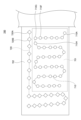
図6は、本実施形態に係るショベル100が撮像を行った位置を示した図である。図6に示される例では、作業現場700において、2台のショベル(第1ショベル100A、第2ショベル100B)が作業している。図6に示される例では、ショベル毎に作業する領域が分けられている。具体的には、第1ショベル100Aは作業領域701(破線で囲まれた領域)で作業を行い、第2ショベル100Bは、作業領域702(破線で囲まれた領域の外側にある領域)で作業を行う。 <Specific example of the position where theexcavator 100 captured the image>
FIG. 6 is a diagram showing positions at which theexcavator 100 according to the present embodiment performs imaging. In the example shown in FIG. 6 , two excavators (first excavator 100A and second excavator 100B) are working at a work site 700 . In the example shown in FIG. 6, the working area is divided for each excavator. Specifically, the first excavator 100A works in a work area 701 (area surrounded by dashed lines), and the second excavator 100B works in a work area 702 (area outside the area surrounded by dashed lines). I do.
図6は、本実施形態に係るショベル100が撮像を行った位置を示した図である。図6に示される例では、作業現場700において、2台のショベル(第1ショベル100A、第2ショベル100B)が作業している。図6に示される例では、ショベル毎に作業する領域が分けられている。具体的には、第1ショベル100Aは作業領域701(破線で囲まれた領域)で作業を行い、第2ショベル100Bは、作業領域702(破線で囲まれた領域の外側にある領域)で作業を行う。 <Specific example of the position where the
FIG. 6 is a diagram showing positions at which the
図6に示される例では、第1ショベル100A、及び第2ショベル100Bは、予め定められた距離を移動する毎に、撮像装置40を用いて撮像を行う。撮像するための距離の間隔は、実施態様に応じて定められる。なお、撮像装置40が撮像を行うタイミングは、予め定められた距離を移動する毎に制限するものではなく、例えば、予め定められた時間が経過する毎に撮像を行う手法を用いてもよい。また、作業現場700全域について撮像を行うために、作業と関係なくショベル100毎に割り当てられた領域を走行してもよいし、各ショベル100が担当している作業領域で作業を行っている中に撮像してもよい。作業現場700で作業している複数のショベル100の撮像結果を組み合わせることで、作業現場全体の各位置で撮影された撮像画像データを確保できる。
In the example shown in FIG. 6, the first excavator 100A and the second excavator 100B capture an image using the imaging device 40 each time they move a predetermined distance. The distance interval for imaging is determined according to the embodiment. Note that the timing at which the imaging device 40 takes an image is not limited to each time a predetermined distance is moved. Further, in order to capture images of the entire work site 700, each excavator 100 may travel in an assigned area regardless of the work, or while each excavator 100 is working in the work area assigned to it. may be imaged. By combining the imaging results of a plurality of excavators 100 working at the work site 700, it is possible to secure captured image data captured at each position of the entire work site.
第1ショベル100Aは、第1の位置座標710Aを起点として、移動軌跡710に従って移動している。そして、第1ショベル100Aの撮像装置40は、第1ショベル100Aが予め定められた距離を移動する毎に、丸マーク"〇"で示された位置で撮像を行っている。
The first excavator 100A is moving along a movement trajectory 710 with a first position coordinate 710A as a starting point. Then, the imaging device 40 of the first excavator 100A takes an image at the position indicated by the circle mark "O" each time the first excavator 100A moves a predetermined distance.
同様に、第2ショベル100Bは、第1の位置座標720Aを起点として、移動軌跡720に従って移動している。そして、第2ショベル100Bの撮像装置40は、第2ショベル100Bが予め定められた距離を移動する毎に、四角マーク"◇"で示された位標ごとに撮像を行っている。
Similarly, the second excavator 100B moves along the movement trajectory 720 with the first position coordinates 720A as the starting point. Then, the imaging device 40 of the second excavator 100B captures an image of each marker indicated by a square mark "◇" each time the second excavator 100B moves a predetermined distance.
第1ショベル100A及び第2ショベル100Bの送信処理部3003は、撮像を行った位置毎に、当該位置に対応する送信データ5005を、管理装置300に送信する。
The transmission processing unit 3003 of the first excavator 100A and the second excavator 100B transmits the transmission data 5005 corresponding to each imaged position to the management device 300.
これにより、管理装置300は、第1ショベル100A及び第2ショベル100Bに作業領域を分担した場合でも、作業現場700の全領域の撮像画像データを受信できる。
As a result, the management device 300 can receive captured image data of the entire area of the work site 700 even when the work area is shared between the first excavator 100A and the second excavator 100B.
従って、後述する通信端末400は、第1ショベル100A及び第2ショベル100Bのいずれが撮像したかにかかわらず、撮像画像データに基づいた作業現場の状況を把握できる。なお、撮像を行った位置と、表示される画面と、の対応関係については後述する。
Therefore, the communication terminal 400, which will be described later, can grasp the situation of the work site based on the captured image data regardless of which of the first excavator 100A and the second excavator 100B captured the image. Note that the correspondence relationship between the position where the image was captured and the screen to be displayed will be described later.
また、第1ショベル100A及び第2ショベル100Bが、以前通った移動経路を、再び通る場合であっても、予め定められた距離を移動する毎に撮像を行う。これにより管理装置300は、略同一の位置で異なる時刻に撮像された複数の撮像画像データを受信できる。したがって、管理装置300は、略同一の位置における、時間の経過に伴う作業現場の変化を保存できる。
In addition, even when the first excavator 100A and the second excavator 100B pass through the previously traveled route again, images are captured each time they travel a predetermined distance. As a result, the management device 300 can receive a plurality of captured image data captured at substantially the same position at different times. Therefore, the management device 300 can store changes in the work site over time at substantially the same position.
<管理装置の制御系>
次に、図4に示される管理装置300の制御系について説明する。管理装置300は、制御装置310と、通信機器320と、出力装置330と、入力装置340と、を含む。 <Control system of management device>
Next, the control system of themanagement device 300 shown in FIG. 4 will be described. The management device 300 includes a control device 310 , a communication device 320 , an output device 330 and an input device 340 .
次に、図4に示される管理装置300の制御系について説明する。管理装置300は、制御装置310と、通信機器320と、出力装置330と、入力装置340と、を含む。 <Control system of management device>
Next, the control system of the
通信機器320は、通信ネットワークNWを通じて、ショベル100及び通信端末400等の外部装置と通信を行う任意のデバイスである。
The communication device 320 is any device that communicates with external devices such as the excavator 100 and the communication terminal 400 through the communication network NW.
出力装置330は、例えば、ディスプレイを含み、制御装置310による制御下で、各種情報画像を表示する。
The output device 330 includes, for example, a display, and displays various information images under the control of the control device 310.
入力装置340は、管理装置300のオペレータによる各種操作入力を受け付け、操作入力に応じた信号を制御装置310に出力する。入力装置340は、例えば、各種情報画像を表示する出力装置330のディスプレイに実装されるタッチパネル、キーボード、マウス等を含みうる。
The input device 340 receives various operational inputs by the operator of the management device 300 and outputs signals corresponding to the operational inputs to the control device 310 . The input device 340 can include, for example, a touch panel mounted on the display of the output device 330 that displays various information images, a keyboard, a mouse, and the like.
制御装置310は、管理装置300における各種動作を制御する。制御装置310は、例えば、不揮発性の補助記憶装置にインストールされる一以上のプログラムをCPU上で実行することにより実現される機能部として、受信処理部3101と、合成部3102と、保存部3103と、表示画像生成部3104と、送信処理部3105とを含む。また、制御装置310は、例えば、補助記憶装置等の不揮発性の内部メモリに規定される記憶領域としての合成画像記憶部350を含む。
The control device 310 controls various operations in the management device 300 . The control device 310 includes, for example, a reception processing unit 3101, a synthesis unit 3102, and a storage unit 3103 as functional units realized by executing one or more programs installed in a nonvolatile auxiliary storage device on the CPU. , a display image generation unit 3104 , and a transmission processing unit 3105 . The control device 310 also includes, for example, a composite image storage unit 350 as a storage area defined in a nonvolatile internal memory such as an auxiliary storage device.
なお、合成画像記憶部350に相当する記憶領域は、制御装置310と通信可能に接続される外部記憶装置に設けられてもよい。
A storage area corresponding to the composite image storage unit 350 may be provided in an external storage device communicably connected to the control device 310 .
受信処理部3101は、通信機器320を用いて、通信端末400又はショベル100からの情報の受信を制御する。
The reception processing unit 3101 uses the communication device 320 to control reception of information from the communication terminal 400 or the excavator 100 .
例えば、受信処理部3101は、第1ショベル100A及び第2ショベル100Bの各々から、撮像画像データと各種情報とが対応付けられた送信データ5005の受信を制御する。
For example, the reception processing unit 3101 controls reception of transmission data 5005 in which captured image data and various types of information are associated with each other from each of the first excavator 100A and the second excavator 100B.
本実施形態に係る受信処理部3101は、ショベル100が予め定められた距離を移動する毎に撮像された撮像画像データを含む送信データ5005を受信する。また、受信処理部3101が、ショベル100が同じ場所を往復する場合等においては、同一の作業現場の同じ場所で撮像された撮像画像データを含んだ送信データ5005を繰り返して受信することもある。このような場合に、同じ位置で異なる時刻で撮像された撮像画像データが格納される。これにより、時刻の変化に応じたショベル100周辺の変化を保存できる。
The reception processing unit 3101 according to the present embodiment receives transmission data 5005 including captured image data captured each time the excavator 100 moves a predetermined distance. Further, when the excavator 100 makes a round trip to and from the same place, the reception processing unit 3101 may repeatedly receive the transmission data 5005 including the captured image data captured at the same place in the same work site. In such a case, captured image data captured at different times at the same position are stored. As a result, changes in the vicinity of the excavator 100 according to changes in time can be saved.
本実施形態では、受信処理部3101が受信する送信データ5005(図5参照)には、ショベル100で異なる方向を撮像した4枚の撮像画像データを含むと共に、各種情報が含まれている。
In this embodiment, the transmission data 5005 (see FIG. 5) received by the reception processing unit 3101 includes data of four captured images captured in different directions by the excavator 100 and various information.
合成部3102は、受信処理部3101が受信した送信データ5005に含まれている、方向、時刻、及び位置のうち少なくとも一つが異なる撮像画像データを合成する。例えば、受信処理部3101が受信した送信データ5005に含まれている、撮影された位置及び時刻が同じであると共に、撮像した方向が異なる4枚の撮像画像データを合成して、撮影した時にショベル100の周辺を表した俯瞰画像データを生成する。
The synthesizing unit 3102 synthesizes captured image data different in at least one of direction, time, and position included in the transmission data 5005 received by the reception processing unit 3101 . For example, four pieces of captured image data, which are included in the transmission data 5005 received by the reception processing unit 3101 and which are taken at the same position and at the same time and taken in different directions, are synthesized, and when the image is taken, the shovel Bird's-eye view image data representing the periphery of 100 is generated.
合成部3102は、複数の送信データ5005から一つの合成画像データを生成してもよい。例えば、合成部3102は、同じ位置で異なる時刻に撮像された複数の送信データ5005から、抽出された複数の撮像画像データを、撮像された位置又は方位に基づいて合成してもよい。
The synthesizing unit 3102 may generate one synthetic image data from a plurality of pieces of transmission data 5005. For example, the synthesizing unit 3102 may synthesize a plurality of captured image data extracted from a plurality of transmission data 5005 captured at the same position at different times based on the captured position or orientation.
例えば、時刻Aに撮像した撮像画像データでは、ショベル100の左側に障害物が写っているが、ショベル100の右側に障害物が写ってなく、時刻Bに撮像した撮像画像データでは、ショベル100の左側に障害物が写っていないが、ショベル100の右側に障害物が写っている場合がある。この場合、合成部3102は、時刻Aの撮像画像データ、及び時刻Bの撮像画像データのうち、障害物が写っていない撮像画像データを組み合わせて、俯瞰画像データを合成してもよい。これにより、当該位置を基準に周囲の物体の映り込みが少ない俯瞰画像データ(合成画像データの一例)を生成できる。つまり、合成部3102は、複数の撮像画像データを組み合わせることで視認性が向上した俯瞰画像データを生成できる。
For example, in the captured image data captured at time A, an obstacle appears on the left side of the excavator 100, but no obstacle appears on the right side of the excavator 100. Although no obstacle is shown on the left side, an obstacle may be shown on the right side of the excavator 100 . In this case, the synthesizing unit 3102 may combine the captured image data at time A and the captured image data at time B, in which the obstacle is not captured, to synthesize bird's-eye view image data. As a result, it is possible to generate bird's-eye view image data (an example of composite image data) in which surrounding objects are less reflected on the basis of the position. That is, the synthesizing unit 3102 can generate bird's-eye view image data with improved visibility by combining a plurality of captured image data.
図7は、本実施形態に係る合成部3102によって撮像画像データを組み合わせて俯瞰画像データを生成する概念を示した図である。図7に示される例では、合成部3102が、撮像装置40が撮像した撮像画像データのうち、ショベル100が存在する位置を中心として、4方向の各々について、障害物が写っていない撮像画像データ1701~1704を抽出し、抽出された撮像画像データ1701~1704を合成して、俯瞰画像データ1705を生成している。図7に示される撮像画像データ1701~1704のうち、例えば、撮像画像データ1701、1703、1704が時刻Aに撮像された撮像画像であって、撮像画像データ1702が時刻Bに撮像された撮像画像とする。つまり、時刻Aではショベル100の左側には障害物が存在するが、時刻Bではショベル100の左側に障害物が存在しないため、俯瞰画像データ1705を生成する際に、時刻Bで撮影された撮像画像データ1702に差し替えられている。
FIG. 7 is a diagram showing the concept of generating bird's-eye view image data by combining captured image data by the synthesizing unit 3102 according to this embodiment. In the example shown in FIG. 7, the synthesizing unit 3102 generates captured image data in which obstacles are not captured in each of four directions centering on the position where the excavator 100 exists, among the captured image data captured by the imaging device 40. 1701 to 1704 are extracted, and the extracted captured image data 1701 to 1704 are synthesized to generate overhead image data 1705 . Among the captured image data 1701 to 1704 shown in FIG. 7, for example, captured image data 1701, 1703, and 1704 are captured images captured at time A, and captured image data 1702 is captured images captured at time B. and That is, an obstacle exists on the left side of the excavator 100 at time A, but no obstacle exists on the left side of the excavator 100 at time B. It is replaced with image data 1702 .
図4に戻り、保存部3103は、作業現場ごとに、合成部3102によって合成された俯瞰画像データを、当該送信データ5005に含まれていた各種情報、例えば、位置座標(緯度、及び経度)、ショベル100の向いている方向、日時情報(時刻を含む)、作業工程を示した情報を対応付けて、合成画像記憶部350に保存する。これにより、送信データ5005が送信される毎に、合成された俯瞰画像データが、合成画像記憶部350に保存される。
Returning to FIG. 4, the storage unit 3103 saves the bird's-eye view image data synthesized by the synthesizing unit 3102 for each work site as various information included in the transmission data 5005, such as position coordinates (latitude and longitude), The direction in which the excavator 100 is facing, date information (including time), and information indicating the work process are associated with each other and stored in the composite image storage unit 350 . As a result, the synthesized bird's-eye view image data is stored in the synthesized image storage unit 350 each time the transmission data 5005 is transmitted.
なお、本実施形態に係る保存部3103は、俯瞰画像データを、各種情報と対応付けて合成画像記憶部350に保存する例について説明する。本実施形態は、4枚の撮像画像データを合成した後の俯瞰画像データを保存する手法に制限するものではなく、送信データ5005に含まれている、4枚の撮像画像データをそのまま保存してもよい。この場合、記憶されていた撮像画像データを読み出した段階で、合成部3102が、読み出した撮像画像データから俯瞰画像データを合成してもよいし、通信端末400が撮像画像データから俯瞰画像を合成してもよい。
Note that an example in which the storage unit 3103 according to the present embodiment stores overhead image data in the composite image storage unit 350 in association with various types of information will be described. This embodiment is not limited to the method of storing the bird's-eye view image data after combining the four captured image data. good too. In this case, at the stage of reading the stored captured image data, the synthesizing unit 3102 may synthesize overhead image data from the read captured image data, or the communication terminal 400 may synthesize the overhead image from the captured image data. You may
本実施形態に係る保存部3103は、ショベル100が動作している間、ショベル100等が移動している位置毎に、俯瞰画像データと各種情報とを対応付けて保存できる。図6に示される例では、丸マーク"〇"で示された位置毎、及び四角マーク"◇"で示される位置毎に、俯瞰画像データと、各種情報と、が対応付けられて保存される。保存される各種情報は、上述した送信データ5005として格納された各種情報と同様のため、説明を省略する。
The storage unit 3103 according to the present embodiment can associate and store bird's-eye view image data and various types of information for each position where the excavator 100 or the like is moving while the excavator 100 is operating. In the example shown in FIG. 6, bird's-eye view image data and various types of information are associated and stored for each position indicated by a circle mark "○" and for each position indicated by a square mark "◇". . The various information to be saved is the same as the various information stored as the transmission data 5005 described above, so description thereof will be omitted.
また、保存部3103は、上述した情報を作業現場ごとに合成画像記憶部350に記憶する。その際に、保存部3103は、作業現場の位置(例えば、住所、且つ緯度経度)及び名称を示す情報も合成画像記憶部350に保存する。これにより、ユーザは、表示したい作業現場を選択できる。
In addition, the storage unit 3103 stores the above-described information in the composite image storage unit 350 for each work site. At that time, the storage unit 3103 also stores information indicating the location (for example, address and latitude/longitude) and name of the work site in the composite image storage unit 350 . This allows the user to select the worksite that they wish to view.
表示画像生成部3104は、合成画像記憶部350に保存された俯瞰画像データから、通信端末400に表示するための表示画像データを生成する。生成される表示画像データとは、ショベル100や人等の視点から当該作業現場を見たように表示される画像データである。
The display image generation unit 3104 generates display image data for display on the communication terminal 400 from the overhead image data stored in the composite image storage unit 350 . The generated display image data is image data displayed as if the work site was viewed from the viewpoint of the excavator 100, a person, or the like.
本実施形態に係る表示画像生成部3104は、俯瞰画像データを、仮想的な3次元空間モデルに投影することで、作業現場を示した仮想的な3次元空間データを生成する。なお、3次元空間モデルとは、例えば円筒形状などが考えられる。円筒形状の側面及び底面に俯瞰画像データを投影することで、ショベル100を中心とした仮想的な3次元空間を実現できる。そして、表示画像生成部3104は、3次元空間データで示された仮想的な3次元空間内で、ショベル100が存在していた位置を視点とし、所定の方向を視線(目で見ている方向)として、2次元の仮想平面に再投影する。これにより、ショベル100が存在した位置から、作業現場を見ているように表された表示画像データを生成できる。
The display image generation unit 3104 according to the present embodiment generates virtual three-dimensional space data representing the work site by projecting the bird's-eye view image data onto a virtual three-dimensional space model. Note that the three-dimensional space model may be, for example, a cylindrical shape. A virtual three-dimensional space centered on the excavator 100 can be realized by projecting the bird's-eye view image data onto the cylindrical side and bottom surfaces. Then, the display image generation unit 3104 sets the position where the excavator 100 existed in the virtual three-dimensional space indicated by the three-dimensional space data as the viewpoint, and the line of sight (the direction viewed by the eyes) is set in a predetermined direction. ) and reprojected onto a two-dimensional virtual plane. As a result, it is possible to generate display image data representing the work site as if viewed from the position where the excavator 100 was present.
さらに、本実施形態に係る表示画像生成部3104は、俯瞰画像データに対応付けられた、ショベル100の傾きを示す情報が存在する場合に、ショベル100の傾きを考慮して仮想3次元モデルに投影した上で、任意の視点から作業現場を見たような表示画像データを生成してもよい。これにより、表示画像を参照しているユーザに対して、作業現場の傾きを含めた状況を認識させることができる。なお、本実施形態は、表示画像データの生成に、俯瞰画像データを用いる例について説明した。しかしながら、本実施形態は、表示画像データの生成に俯瞰画像データを用いる手法に制限するものではなく、例えば、撮像画像データから表示画像データを生成してもよいし、撮像画像データを表示画像データとして用いてもよい。
Furthermore, when there is information indicating the tilt of the excavator 100 associated with the bird's-eye view image data, the display image generation unit 3104 according to the present embodiment projects the tilt of the excavator 100 onto the virtual three-dimensional model. After that, display image data as if the work site is viewed from an arbitrary viewpoint may be generated. This allows the user who is referring to the display image to recognize the situation including the inclination of the work site. In this embodiment, an example in which bird's-eye view image data is used to generate display image data has been described. However, the present embodiment is not limited to the technique of using bird's-eye view image data for generating display image data. For example, display image data may be generated from captured image data, or captured image data may may be used as
送信処理部3105は、通信機器320を用いて、通信端末400又はショベル100に対する情報の送信を制御する。
The transmission processing unit 3105 uses the communication device 320 to control transmission of information to the communication terminal 400 or the excavator 100 .
具体的には、送信処理部3105は、表示画像生成部3104が生成した表示画像データ(合成された画像の一例)を、通信端末400に送信する。例えば、受信処理部3101が、通信端末400から、方向、時間帯又は時刻、及び位置のうち少なくとも一つの指定された上で表示画像データの送信要求を受信していた場合、送信処理部3105は、当該指定に応じて、指定された方向、時間帯又は時刻、及び位置のうち少なくとも一つに基づいて生成された表示画像データを、通信端末400に送信する。本実施形態では、任意の視点から作業現場を見たような表示画像データを表示させるための制御の一例として、表示画像データを通信端末400に送信する場合について説明した。なお、表示画像データを表示させるための制御としては、表示画像データを通信端末400への送信に制限するものではなく、表示画像データの表示制御であってもよい。
Specifically, the transmission processing unit 3105 transmits the display image data (an example of the synthesized image) generated by the display image generation unit 3104 to the communication terminal 400 . For example, if the reception processing unit 3101 receives a request to transmit display image data from the communication terminal 400 with at least one of direction, time period or time, and position specified, the transmission processing unit 3105 , according to the designation, display image data generated based on at least one of the designated direction, time period or time, and position is transmitted to the communication terminal 400 . In the present embodiment, the case of transmitting the display image data to the communication terminal 400 has been described as an example of control for displaying the display image data as if the work site was viewed from an arbitrary viewpoint. Note that the control for displaying the display image data is not limited to transmission of the display image data to communication terminal 400, and may be display control of the display image data.
管理装置300が表示画像データを送信することで、通信端末400が、ショベル100が撮像を行った位置からの所定の方向を見ているように表された表示画像データを表示できる。当該表示画像データは、俯瞰画像データと比べて、表示される画角は狭いが、人の視野角に近い画角で、ショベル100の状況を表している。このような表示画像データを表示できるので、当該通信端末400のユーザは違和感なく、ショベル100の周囲の状況を把握できる。
By transmitting the display image data from the management device 300, the communication terminal 400 can display the display image data as if the excavator 100 were looking in a predetermined direction from the position where the image was taken. The display image data has a narrower angle of view than the bird's-eye view image data, but represents the situation of the excavator 100 at an angle of view close to the human viewing angle. Since such display image data can be displayed, the user of the communication terminal 400 can understand the surroundings of the excavator 100 without any discomfort.
また、本実施形態は、送信処理部3105が送信するデータ(合成画像データに基づいた情報の一例)を、任意の視点から作業現場を見たような表示画像データに制限するものではなく、俯瞰画像データ、又は4枚の撮像画像データ等でもよい。これにより、通信端末400のユーザは、所望する態様で、作業現場の視認できるので、作業現場の状況の把握が容易になる。また、通信端末400は、俯瞰画像データを受信した場合に、俯瞰画像データから任意の視点から作業現場を見たような表示画像データを生成して表示してもよいし、俯瞰画像データをそのまま表示してもよい。
In addition, in the present embodiment, the data transmitted by the transmission processing unit 3105 (an example of information based on the composite image data) is not limited to display image data as if the work site was viewed from an arbitrary viewpoint. Image data, or image data of four images, or the like may be used. As a result, the user of communication terminal 400 can visually recognize the work site in a desired manner, thereby facilitating understanding of the situation of the work site. Further, when receiving the overhead image data, the communication terminal 400 may generate and display display image data as if the work site was viewed from an arbitrary viewpoint from the overhead image data, or may display the overhead image data as it is. may be displayed.
<俯瞰画像データの具体例>
図8は、本実施形態に係る管理装置300の合成部3102により生成された俯瞰画像データの一例を示した図である。図8に示される俯瞰画像データは、ショベル100に設けられた4個の撮像装置40に基づいて生成された画像であって、ショベル100から上方に所定の距離だけ離れた視点から、ショベル100の周囲を表している。図8に示されるように俯瞰画像データは、ショベル100の周囲360度の周囲の状況が表されている。 <Specific example of overhead image data>
FIG. 8 is a diagram showing an example of bird's-eye view image data generated by thesynthesizing unit 3102 of the management device 300 according to this embodiment. The bird's-eye view image data shown in FIG. 8 is an image generated based on the four imaging devices 40 provided on the excavator 100, and is an image of the excavator 100 viewed from a viewpoint a predetermined distance above the excavator 100. represents the surroundings. As shown in FIG. 8 , the bird's-eye view image data represents the 360-degree surroundings of the excavator 100 .
図8は、本実施形態に係る管理装置300の合成部3102により生成された俯瞰画像データの一例を示した図である。図8に示される俯瞰画像データは、ショベル100に設けられた4個の撮像装置40に基づいて生成された画像であって、ショベル100から上方に所定の距離だけ離れた視点から、ショベル100の周囲を表している。図8に示されるように俯瞰画像データは、ショベル100の周囲360度の周囲の状況が表されている。 <Specific example of overhead image data>
FIG. 8 is a diagram showing an example of bird's-eye view image data generated by the
図8に示されるように、俯瞰画像データは、ショベル100を表したアイコンTCGを中心とした等距離線EQLを示している。また、俯瞰画像データは、ショベル100の近傍に存在する物体だけではなく、ショベル100から見て水平方向の遠方に存在する物体(例えば、山601や、煙突602)なども写っている。
As shown in FIG. 8 , the bird's-eye view image data indicates equidistant lines EQL centered on the icon TCG representing the excavator 100 . Moreover, the bird's-eye view image data includes not only objects existing near the excavator 100 but also objects existing horizontally distant from the excavator 100 (for example, a mountain 601 and a chimney 602).
上述したように、俯瞰画像データは、仮想的な3次元空間モデルに投影されることで、当該3次元空間に存在する任意の視点からショベル100の周囲を表している表示画像データを生成できる。つまり、本実施形態においては、上述したように、俯瞰画像データを用いて、任意の視点から作業現場を見た画面を生成し、表示できる。本実施形態では、任意の視点から作業現場を見た画面を表示するために用いる画像データを、俯瞰画像データに制限するものではなく、予め任意の視点から作業現場を撮像した画像データを用いてもよいし、それ以外の種類の画像データを用いてもよい。
As described above, by projecting the bird's-eye view image data onto a virtual three-dimensional space model, it is possible to generate display image data representing the surroundings of the excavator 100 from an arbitrary viewpoint existing in the three-dimensional space. That is, in the present embodiment, as described above, it is possible to generate and display a screen of a work site viewed from an arbitrary viewpoint using bird's-eye view image data. In this embodiment, the image data used to display the screen of the work site viewed from an arbitrary viewpoint is not limited to bird's-eye view image data. Alternatively, other types of image data may be used.
<通信端末の制御系>
次に、図4に示される通信端末400の制御系について説明する。通信端末400は、制御装置410と、通信機器420と、表示装置430と、入力装置440とを含む。 <Control system of communication terminal>
Next, the control system ofcommunication terminal 400 shown in FIG. 4 will be described. Communication terminal 400 includes control device 410 , communication device 420 , display device 430 , and input device 440 .
次に、図4に示される通信端末400の制御系について説明する。通信端末400は、制御装置410と、通信機器420と、表示装置430と、入力装置440とを含む。 <Control system of communication terminal>
Next, the control system of
通信機器420は、通信ネットワークNWを通じて、管理装置300等の外部装置と通信を行う任意のデバイスである。通信機器420は、例えば、LTE、4G、5G等の移動体通信規格に対応する移動体通信モジュールである。
The communication device 420 is any device that communicates with an external device such as the management device 300 through the communication network NW. The communication device 420 is, for example, a mobile communication module compatible with mobile communication standards such as LTE, 4G, and 5G.
表示装置430は、各種情報画像を表示する。表示装置430は、例えば、液晶ディスプレイや有機ELディスプレイである。
The display device 430 displays various information images. The display device 430 is, for example, a liquid crystal display or an organic EL display.
入力装置440は、ユーザからの通信端末400における各種操作を受け付ける操作部の一例である。入力装置440は、例えば、ボタン、表示装置430に実装されるタッチパネル等のハードウェアによる操作部を含む。また、入力装置440は、表示装置430に実装されるタッチパネル等のハードウェアによる操作部と、表示装置430に表示される操作画面上のボタンアイコン等のソフトウェアによる操作部との組み合わせでもよい。
The input device 440 is an example of an operation unit that receives various operations on the communication terminal 400 from the user. The input device 440 includes, for example, a hardware operation unit such as buttons and a touch panel mounted on the display device 430 . Further, the input device 440 may be a combination of a hardware operation unit such as a touch panel mounted on the display device 430 and a software operation unit such as button icons on the operation screen displayed on the display device 430 .
制御装置410は、通信端末400の各種動作を制御する。制御装置410は、例えば、不揮発性の補助記憶装置等にインストールされる一以上のプログラムを実行することにより実現される機能部として、画像表示処理部4101と、入力処理部4102と、送信処理部4103と、受信処理部4104と、を実現する。
The control device 410 controls various operations of the communication terminal 400 . The control device 410 includes, for example, an image display processing unit 4101, an input processing unit 4102, and a transmission processing unit as functional units realized by executing one or more programs installed in a nonvolatile auxiliary storage device or the like. 4103 and a reception processing unit 4104 are realized.
画像表示処理部4101、入力処理部4102、送信処理部4103、及び受信処理部4104、等の機能は、ユーザの入力装置440に対する所定操作に応じて、制御装置410にインストールされる所定のアプリケーションプログラム(以下、「現場表示アプリケーション」)が起動されることにより有効になる態様であってもよい。
Functions such as the image display processing unit 4101, the input processing unit 4102, the transmission processing unit 4103, and the reception processing unit 4104 are performed by a predetermined application program installed in the control device 410 according to a predetermined operation on the input device 440 by the user. (hereinafter referred to as "site display application") may be enabled by starting.
現場表示アプリケーションとは、ショベル100の撮像装置40が撮像した撮像画像データに基づいた、任意の視点から作業現場の状況を表した表示画像データを表示するために用いるアプリケーションである。本実施形態では、現場表示アプリケーションを起動した際に、作業現場の一覧画面が表示される。
The site display application is an application used to display display image data representing the situation of the work site from an arbitrary viewpoint based on the captured image data captured by the imaging device 40 of the excavator 100 . In this embodiment, a work site list screen is displayed when the site display application is started.
画像表示処理部4101は、現場表示アプリケーションに関する画面を、表示装置430に表示するための処理を行う。例えば、画像表示処理部4101は、作業現場の一覧画面を表示する。ユーザは、作業現場の一覧画面から、表示したい作業現場の選択と、当該作業現場内で表示したい位置と、を指定できる。
The image display processing unit 4101 performs processing for displaying a screen related to the on-site display application on the display device 430 . For example, the image display processing unit 4101 displays a work site list screen. The user can select a work site to be displayed and specify a position to be displayed within the work site from the work site list screen.
入力処理部4102は、入力装置440を介して、現場表示アプリケーションに関する画面で、ユーザの各種操作に対応する入力処理を行う。例えば、入力処理部4102は、選択された作業現場と、指定された位置と、を入力処理する。また、入力処理部4102が、入力処理する情報は、選択された作業現場と、指定された位置と、の組み合わせに制限するものではない。入力処理する情報は、作業現場のみでもよいし、作業現場が特定されている場合には、位置、時刻及び方向のうち少なくとも一つ以上あってもよい。
The input processing unit 4102 performs input processing corresponding to various user operations on the screen related to the on-site display application via the input device 440 . For example, the input processing unit 4102 inputs the selected work site and the designated position. Information to be input and processed by the input processing unit 4102 is not limited to the combination of the selected work site and the designated position. The information to be input and processed may be only the work site, or may include at least one of position, time, and direction when the work site is specified.
送信処理部4103は、通信機器420を用いて、管理装置300に対して情報を送信処理する。
The transmission processing unit 4103 uses the communication device 420 to transmit information to the management device 300 .
例えば、入力処理部4102が、選択された作業現場と、指定された位置と、を入力処理した場合に、送信処理部4103は、当該作業現場及び指定された位置に関する情報の送信要求を、管理装置300に送信する。このように、送信処理部4103は、入力処理部4102によって入力処理された情報による送信要求(例えば、位置、時刻及び方向のうち少なくとも一つ以上)を、管理装置300に送信する。
For example, when the input processing unit 4102 performs input processing of a selected work site and a designated position, the transmission processing unit 4103 manages a request to transmit information regarding the work site and the designated position. Send to device 300 . In this way, the transmission processing unit 4103 transmits to the management device 300 a transmission request (for example, at least one of position, time, and direction) based on the information input and processed by the input processing unit 4102 .
受信処理部4104は、通信機器420を用いて、管理装置300からの情報を受信処理する。
The reception processing unit 4104 uses the communication device 420 to receive and process information from the management device 300 .
例えば、送信処理部4103の送信要求に伴い、受信処理部4104は、作業現場の指定された位置から見た作業現場の状況を表した表示画像データを受信処理する。
For example, in response to a transmission request from the transmission processing unit 4103, the reception processing unit 4104 receives and processes display image data representing the situation of the work site as seen from a specified position on the work site.
そして、画像表示処理部4101は、受信処理部4104が受信した表示画像データを表示する。本実施形態では、通信端末400(情報処理装置の一例)が、指定された位置から見た作業現場の状況を表した表示画像データを表示する例について説明するが、表示する画像データを制限するものではなく、俯瞰画像データを表示してもよいし、撮像画像データそのものを表示してもよい。つまり、ショベル100によって撮像された撮像画像データに関する表示であればよい。
Then, the image display processing unit 4101 displays the display image data received by the reception processing unit 4104. In the present embodiment, an example in which the communication terminal 400 (an example of an information processing device) displays display image data representing the situation of the work site as viewed from a specified position will be described. It is also possible to display bird's-eye view image data instead of objects, or to display captured image data itself. In other words, any display related to captured image data captured by the excavator 100 may be used.
指定された位置から見た作業現場を表した表示画像データを表示した後であっても、入力処理部4102が、作業現場に関する指定(撮像したショベル100の位置、表示したい方向、及び時間帯)を受け付けた場合に、送信処理部4103が、当該指定とともに送信要求を、管理装置300に送信する。
Even after the display image data representing the work site viewed from the specified position is displayed, the input processing unit 4102 can specify the work site (the position of the excavator 100 captured, the direction to be displayed, and the time zone). is received, the transmission processing unit 4103 transmits a transmission request to the management device 300 together with the designation.
受信処理部4104は、当該送信要求に伴い、管理装置300から、ユーザに指定された方向、時刻、及び位置のうちの少なくとも一つに対応付けられた表示画像データを受信する。画像表示処理部4101は、受信した表示画像データを表示する。これにより、ユーザの指定に応じた作業現場の状況の把握が容易になる。
In response to the transmission request, the reception processing unit 4104 receives display image data associated with at least one of the direction, time, and position specified by the user from the management device 300 . The image display processing unit 4101 displays the received display image data. This makes it easier to grasp the situation of the work site according to the user's designation.
<作業現場の一覧画面>
図9は、本実施形態に係る画像表示処理部4101が、表示する作業現場の一覧画面を示した図である。図9は、作業現場欄1301と、地図表示欄1302と、表示開始ボタン1303と、が表されている。作業現場欄1301には、選択可能な作業現場の住所及び名称の一覧が示されている。なお、当該作業現場ごとの住所及び名称の情報は、管理装置300から予め受信した情報とする。ユーザは、作業現場欄1301から表示したい作業現場を選択する。 <Work site list screen>
FIG. 9 is a diagram showing a work site list screen displayed by the image display processing unit 4101 according to the present embodiment. FIG. 9 shows awork site field 1301, a map display field 1302, and a display start button 1303. FIG. The work site column 1301 shows a list of selectable work site addresses and names. The information on the address and name of each work site is assumed to be information received in advance from the management device 300 . The user selects a work site to be displayed from the work site column 1301 .
図9は、本実施形態に係る画像表示処理部4101が、表示する作業現場の一覧画面を示した図である。図9は、作業現場欄1301と、地図表示欄1302と、表示開始ボタン1303と、が表されている。作業現場欄1301には、選択可能な作業現場の住所及び名称の一覧が示されている。なお、当該作業現場ごとの住所及び名称の情報は、管理装置300から予め受信した情報とする。ユーザは、作業現場欄1301から表示したい作業現場を選択する。 <Work site list screen>
FIG. 9 is a diagram showing a work site list screen displayed by the image display processing unit 4101 according to the present embodiment. FIG. 9 shows a
また、地図表示欄1302には、地図データが表示される。表示される地図データは、作業現場内の地図データに制限するものでなく、より広い範囲の地図データ(例えば、日本国内の地図データ)を表示してもよい。地図表示欄1302に表示される地図データは、ユーザからの操作に応じて拡大、縮小を行ってもよい。
In addition, the map data is displayed in the map display field 1302. The map data to be displayed is not limited to map data within the work site, and map data of a wider range (for example, map data within Japan) may be displayed. The map data displayed in the map display field 1302 may be enlarged or reduced according to the user's operation.
画像表示処理部4101は、当該地図データ(例えば、日本国内の地図データ)上に、作業現場の位置(住所又は緯度経度)に従って、作業現場が存在することを示すアイコン(例えばアイコン1313)を表示する。入力処理部4102は、当該アイコン1313の選択、換言すれば作業現場の選択を受け付ける。アイコン1313の選択を受け付けた場合、作業現場欄1301において、当該アイコン1313と対応している作業現場の位置及び名称が自動的に選択されてもよい。
The image display processing unit 4101 displays an icon (for example, the icon 1313) indicating the presence of a work site on the map data (for example, map data in Japan) according to the location (address or latitude/longitude) of the work site. do. The input processing unit 4102 receives selection of the icon 1313, in other words, selection of the work site. When the selection of the icon 1313 is received, the position and name of the work site corresponding to the icon 1313 may be automatically selected in the work site column 1301 .
そして、入力処理部4102が、表示開始ボタン1303の入力を受け付けた場合、送信処理部4103は、選択された作業現場を示す情報(例えば、位置及び名称)と共に、作業現場に関する情報の送信要求を、管理装置300に送信する。管理装置300は、作業現場に関する情報の送信要求を受信した場合、当該作業現場内のうち、初期設定に基づいて、撮像を行った位置、方向、及び時間帯を指定し、当該指定に対応する表示画像データを生成し、通信端末400に送信する。
Then, when the input processing unit 4102 receives the input of the display start button 1303, the transmission processing unit 4103 requests transmission of information on the work site together with information indicating the selected work site (for example, position and name). , to the management device 300 . When the management device 300 receives a request to send information about a work site, the management device 300 designates the position, direction, and time period in which the image was captured based on the initial settings in the work site, and responds to the designation. Display image data is generated and transmitted to communication terminal 400 .
そして、通信端末400は、管理装置300から、任意の視点から作業現場を見たように表された表示画像データを受信し、受信した表示画像データを表示する。これにより、ユーザは、作業現場を選択するだけで、作業現場に存在するショベル100で撮影された撮像画像データに基づいた表示によって、作業現場の状況を実際に見ているかのような確認が可能となる。
Then, the communication terminal 400 receives the display image data representing the work site viewed from an arbitrary viewpoint from the management device 300, and displays the received display image data. As a result, by simply selecting a work site, the user can confirm the status of the work site as if he or she were actually looking at the display based on the captured image data captured by the excavator 100 present at the work site. becomes.
また、地図表示欄1302には、上述した地図データの表示に制限するものではなく、作業現場欄1301で選択された作業現場の地図データが表示されてもよい。図10は、本実施形態に係る画像表示処理部4101が、表示する作業現場の一覧画面を示した図である。
In addition, the map display column 1302 is not limited to displaying the map data described above, and may display map data of the work site selected in the work site column 1301 . FIG. 10 is a diagram showing a work site list screen displayed by the image display processing unit 4101 according to the present embodiment.
図10に示される例では、作業現場欄1301で選択された作業現場に対応する地図データが、地図表示欄1302に表示された例とする。そして、地図表示欄1302に示される黒丸(例えば符号1311)は、撮像された位置を示している。
In the example shown in FIG. 10, the map data corresponding to the work site selected in the work site column 1301 is displayed in the map display column 1302. A black circle (for example, reference numeral 1311) shown in the map display field 1302 indicates the position where the image was taken.
ユーザは、地図表示欄1302の表示された地図データに表示された黒丸から、表示したい黒丸を指定できる。指定された黒丸は、白丸(例えば白丸1312)に表示が切り替わる。入力処理部4102は、白丸1312で示された位置の指定を受け付ける。さらに、入力処理部4102は、表示開始ボタン1303の入力を受け付けた場合、送信処理部4103は、選択された作業現場及び指定された位置に関する情報の送信要求を、管理装置300に送信する。以降の処理は同様として説明を省略する。これにより、通信端末400は、ユーザが指定した位置に対応する表示画像データを表示できる。そして、ユーザは、指定した位置の周囲の状況を認識できる。
The user can specify a black circle to be displayed from the black circles displayed in the map data displayed in the map display field 1302 . The specified black circle is switched to a white circle (for example, white circle 1312). The input processing unit 4102 accepts designation of the position indicated by the white circle 1312 . Furthermore, when the input processing unit 4102 receives an input from the display start button 1303 , the transmission processing unit 4103 transmits to the management apparatus 300 a transmission request for information regarding the selected work site and the designated position. Subsequent processes are the same, and descriptions thereof are omitted. Thereby, communication terminal 400 can display the display image data corresponding to the position specified by the user. Then, the user can recognize the situation around the designated position.
なお、本実施形態では、作業現場の一覧画面の一例を示したものであって、表示する作業現場に関する設定を別の手法で指定してもよい。作業現場の一覧画面には、当該指定を行うための欄を追加してもよい。例えば、一覧画面には、日付及び時刻の入力を受け付け可能な欄や、方向を受け付け可能な欄が表示されてもよい。
Note that this embodiment shows an example of a list screen of work sites, and settings related to the work sites to be displayed may be designated by another method. A field for making the designation may be added to the work site list screen. For example, the list screen may display a field for accepting input of date and time and a field for accepting direction.
例えば、ユーザは、表示したい時間帯(日付及び時刻含む)を指定してもよい。入力処理部4102は、時間帯の指定を受け付けた後、表示開始ボタンの入力を受け付けた場合、送信処理部4103は、選択された作業現場及び指定された時間帯に関する情報の送信要求を、管理装置300に送信する。これにより、ユーザは、当該作業現場で、指定された時間帯に撮影された表示画像データを認識できる。本実施形態は、作業現場を選択するための画面の一例を示したものであって、他の態様であってもよい。例えば、通信端末400は、検索画面にテキストボックスを表示し、当該テキストボックスに入力された文字列に一致する作業現場の一覧を表示し、当該一覧から作業現場の選択を受け付けてもよい。
For example, the user may specify the time zone (including date and time) that they want to display. When the input processing unit 4102 accepts the input of the display start button after accepting the designation of the time period, the transmission processing unit 4103 manages the transmission request for information regarding the selected work site and the designated time period. Send to device 300 . Thereby, the user can recognize the display image data captured at the work site during the specified time period. This embodiment shows an example of a screen for selecting a work site, and other modes may be used. For example, communication terminal 400 may display a text box on the search screen, display a list of work sites that match the character string input in the text box, and accept selection of a work site from the list.
<表示画像データの表示画面>
図11は、画像表示処理部4101が表示する表示画面を例示した図である。図11に示される表示画面では、任意の視点から作業現場を見たように表された表示画像データ800が表示されると共に、表示画像データ800の下に、表示したい時間帯を設定するためのバー(操作情報の一例)が表示されている。 <Display screen of display image data>
FIG. 11 is a diagram exemplifying a display screen displayed by the image display processing unit 4101. As shown in FIG. On the display screen shown in FIG. 11,display image data 800 is displayed as if the work site was viewed from an arbitrary viewpoint. A bar (an example of operation information) is displayed.
図11は、画像表示処理部4101が表示する表示画面を例示した図である。図11に示される表示画面では、任意の視点から作業現場を見たように表された表示画像データ800が表示されると共に、表示画像データ800の下に、表示したい時間帯を設定するためのバー(操作情報の一例)が表示されている。 <Display screen of display image data>
FIG. 11 is a diagram exemplifying a display screen displayed by the image display processing unit 4101. As shown in FIG. On the display screen shown in FIG. 11,
図11に示される例では、当該バーに対して、10月4日(10/4)の12:00を始点811として設定され、10/4の16:00を終点812として設定されている。このため、時間帯(10/4の12:00~10/4の16:00)内で撮像された撮像画像データに基づいた、表示画像データが表示されている。
In the example shown in FIG. 11, 12:00 on October 4 (10/4) is set as the start point 811 for the bar, and 16:00 on 10/4 is set as the end point 812. Therefore, the display image data based on the captured image data captured within the time period (12:00 on October 4 to 16:00 on October 4) is displayed.
なお、本実施形態は、時間帯の設定をバーに対する操作に制限するものではない。例えば、文字で時間帯を入力してもよい。さらには、具体的な日付や時刻等、例えば、"4日前(1日間)"、"7日前(1日間)"、"12日13時30分"、"最新"等の指定を受け付けてもよい。
Note that this embodiment does not limit the setting of the time period to operations on the bar. For example, you may input a time zone with a character. Furthermore, specific dates and times, for example, "4 days ago (1 day)", "7 days ago (1 day)", "13:30 on the 12th", "latest", etc. can be accepted. good.
このように、ユーザは、表示したい作業現場の時間帯(時刻を含む)を操作によって切り替えることができる。入力処理部4102が時間帯の変更を受け付けた場合、送信処理部4103が、同じ位置であって、変更された時間帯内で撮像された表示画像データの送信要求を、管理装置300に送信する。これにより、受信処理部4104は、同じ位置であって、変更された時間帯に対応する表示画像データを受信する。これにより、画像表示処理部4101が、指定された時間帯の状況を示した表示画像データを表示する。
In this way, the user can switch the time zone (including the time) of the work site to be displayed by operating. When the input processing unit 4102 accepts the change of the time period, the transmission processing unit 4103 transmits to the management device 300 a transmission request for the display image data captured at the same position and within the changed time period. . Accordingly, the reception processing unit 4104 receives the display image data corresponding to the changed time zone at the same position. As a result, the image display processing unit 4101 displays the display image data showing the situation in the designated time period.
このように、ユーザの操作に応じて、表示したい時刻を切り替えられるので、ユーザは指定された時間帯の作業現場の状況を認識できる。例えば、ユーザは、夜間の作業現場の状況、日没時の作業現場の状況、又は日中の作業現場の状況等を容易に確認できる。そして、図11に示される表示画面に対して、ユーザは様々な操作を行うことができる。例えば、ユーザは、視認する方向の切り替えを行うことができる。視認する方向の切り替え手法としてはどのような手法を用いてもよいが、例えば以下に示す手法が考えられる。
In this way, the time to be displayed can be switched according to the user's operation, so the user can recognize the situation at the work site during the specified time period. For example, the user can easily check the situation of the work site at night, the situation of the work site at sunset, the situation of the work site during the day, or the like. Then, the user can perform various operations on the display screen shown in FIG. For example, the user can switch the viewing direction. Although any method may be used as a method for switching the viewing direction, for example, the following method is conceivable.
図11に示される表示画像データにおいて、領域822又は領域821の押下を、入力処理部4102が受け付ける。その後、送信処理部4103が、同じ位置であって、押下された領域822又は領域821に対応する方向(左方又は右方)の表示画像データの送信要求を、管理装置300に送信する。これにより、受信処理部4104は、同じ位置であって、押下された方向に対応する表示画像データを受信する。これにより、画像表示処理部4101が、向きが90度切り替えられた表示画像データを表示する。向きの切り替えは、30度又は45度等の90度以外の角度刻みで行われてもよい。このように、ユーザの操作に応じて、表示したい方向を切り替えられるので、作業現場の状況の確認が容易になる。
In the display image data shown in FIG. 11, the input processing unit 4102 receives pressing of the area 822 or area 821 . After that, the transmission processing unit 4103 transmits to the management device 300 a transmission request for the display image data in the same position and in the direction (leftward or rightward) corresponding to the pressed area 822 or 821 . As a result, the reception processing unit 4104 receives the display image data corresponding to the pressed direction at the same position. As a result, the image display processing unit 4101 displays the display image data whose orientation is switched by 90 degrees. The orientation switching may be performed in angular increments other than 90 degrees, such as 30 degrees or 45 degrees. In this manner, since the direction to be displayed can be switched according to the user's operation, confirmation of the situation at the work site is facilitated.
また、図11に示される表示画面において、ユーザは、当該仮想空間内を移動するかのように、表示する視点の切り替えを行うことができる。
Also, on the display screen shown in FIG. 11, the user can switch the displayed viewpoint as if moving within the virtual space.
具体的には、図11に示される表示画像データ上に、別の位置に視点を切り替えるためのアイコン801(表示情報の一例)が表示されている。表示画像データに表示されるアイコン801は、ショベル100が撮像を行った位置に対応している。本実施形態では、表示画像生成部3104が表示画像データを生成する際に、ショベル100が撮像を行った位置にアイコンを付与したものである。
Specifically, an icon 801 (an example of display information) for switching the viewpoint to another position is displayed on the display image data shown in FIG. An icon 801 displayed in the display image data corresponds to the position where the excavator 100 has taken the image. In the present embodiment, when the display image generation unit 3104 generates display image data, an icon is added to the position where the excavator 100 captured the image.
例えば、図11に示される表示画像データが、図6で示される位置座標710Gからの作業現場の状況を示した表示画像データの場合、位置座標710Fや位置座標710Hに対応する位置に、丸マーク"〇"を示したアイコン801が表される。
For example, if the display image data shown in FIG. 11 is the display image data showing the situation of the work site from the position coordinates 710G shown in FIG. An icon 801 indicating "o" is displayed.
従って、入力処理部4102が、当該アイコン801の押下を入力処理した場合に、送信処理部4103が、当該アイコン801で示した位置から作業現場を見たような表示画像データの要求を、管理装置300に送信する。これにより、通信端末400は、アイコン801に対応する位置で撮像された撮像画像データに基づいた、(当該位置から作業現場を見たような)表示画像データの受信、及び表示を行うことができる。
Therefore, when the input processing unit 4102 performs input processing for pressing the icon 801, the transmission processing unit 4103 requests display image data as if the work site was viewed from the position indicated by the icon 801. 300. As a result, the communication terminal 400 can receive and display display image data based on the captured image data captured at the position corresponding to the icon 801 (as if the work site is viewed from that position). .
つまり、本実施形態に係る表示画像データでは、第1ショベル100Aが存在していた位置に対応するように、押下可能なアイコンが表される。そして、ユーザが、当該アイコンを押下することで、画像表示処理部4101は、撮像が行われた位置に対応する表示画像データに表示を切り替える。換言すれば、ユーザは、表示画像データに付与されているアイコンの押下によって、第1ショベル100Aの移動経路に従った表示画像データの表示の切り替えを実現できる。このように本実施形態に係る周辺画像管理システムSYSでは、ユーザが画像内を移動しているように視点が変化した画像表示(ウォークスルー)を実現できる。これにより本実施形態に係る周辺画像管理システムSYSでは、操作性の向上を実現できる。なお、アイコンが表示される条件は、当該アイコンで示された位置で撮像が行われていると共に、当該撮像が行われた時刻が、ユーザによって設定された時間帯に含まれていることである。例えば、時間帯として一週間が設定された場合に、当該一週間で撮像された位置においては、当該位置を示したアイコンが表示される。これにより、ユーザに指定された時間帯内で撮像された表示画像データ間で表示の切り替えが可能になる。
In other words, in the display image data according to the present embodiment, icons that can be pressed are displayed so as to correspond to the position where the first excavator 100A was present. When the user presses the icon, the image display processing unit 4101 switches the display to the display image data corresponding to the position where the image was captured. In other words, the user can switch the display of the display image data according to the moving route of the first excavator 100A by pressing the icon attached to the display image data. As described above, in the surrounding image management system SYS according to the present embodiment, it is possible to realize an image display (walk-through) in which the viewpoint changes as if the user were moving within the image. As a result, the peripheral image management system SYS according to this embodiment can improve the operability. The conditions for displaying the icon are that the image is captured at the position indicated by the icon and that the time at which the image was captured is included in the time period set by the user. . For example, when one week is set as the time period, an icon indicating the position is displayed at the position where the image was captured during the one week. Thereby, it is possible to switch the display between the display image data captured within the time zone specified by the user.
なお、本実施形態は、表示画像データに表示される、視点を変えるためのアイコンは、"〇"などの移動可能な位置を示した態様に制限するものではない。例えば、移動可能な方向を矢印の形状等で示したアイコン等であってもよい。さらには、本実施形態では、仮想空間内で視点を切り替えるためにアイコンを表示する手法に制限するものではなく、他の手法(例えば文字による移動可能な位置の案内等)を用いてもよい。
It should be noted that, in this embodiment, the icon for changing the viewpoint displayed in the display image data is not limited to a form indicating a movable position such as "o". For example, it may be an icon or the like that indicates the movable direction in the shape of an arrow or the like. Furthermore, the present embodiment is not limited to the method of displaying icons for switching viewpoints in the virtual space, and other methods (for example, guidance of movable positions using characters, etc.) may be used.
本実施形態においては、視点を変えるためのアイコンは、ショベル100の移動経路に従って表示されるものに制限するものではない。図11等に示される表示画像データにおいて、管理装置300が俯瞰画像データを保持している位置であれば、当該視点に変えるためのアイコンを表示してもよい。
In this embodiment, the icons for changing the viewpoint are not limited to those displayed according to the moving route of the shovel 100. In the display image data shown in FIG. 11 and the like, at a position where the management device 300 holds the bird's-eye view image data, an icon for changing to the viewpoint may be displayed.
例えば、本実施形態に係る通信端末400は、第1ショベル100Aが撮像を行った位置に関する表示画像データを表示した場合に、当該位置の近傍に、第2ショベル100Bが撮像を行った位置が存在する場合に、当該第2ショベル100Bが撮像を行った位置に関する表示画像データに切り替えることができる。
For example, when the communication terminal 400 according to the present embodiment displays the display image data related to the position imaged by the first excavator 100A, the position imaged by the second excavator 100B exists in the vicinity of the position. In this case, the display image data can be switched to the position where the image was captured by the second excavator 100B.
図12は、画像表示処理部4101が表示する表示画面を例示した図である。図12に示される表示画面でも、図11と同様に時間帯(時間に関する情報の一例)を設定するためのバーが表示されているが、説明を省略する。
FIG. 12 is a diagram exemplifying a display screen displayed by the image display processing unit 4101. FIG. Although the display screen shown in FIG. 12 also displays a bar for setting the time zone (an example of information about time) as in FIG. 11, the description thereof is omitted.
図12においても、領域922又は領域921の押下を受け付けた場合には、向きが90度切り替えられた表示画像データが表示される。具体的な処理は図11で示した手法と同様のため説明を省略する。
Also in FIG. 12, when the pressing of the area 922 or the area 921 is accepted, the display image data whose orientation is switched by 90 degrees is displayed. Since the specific processing is the same as the method shown in FIG. 11, the description is omitted.
本実施形態においては、表示画面に表示される表示画像データ900上に、別の位置に視点を切り替えるためのアイコン901が表示されている。当該アイコン901は、管理装置300の表示画像生成部3104が表示画像データ900を生成した際に、当該表示画像データ900に付与されたものである。
In this embodiment, an icon 901 for switching the viewpoint to another position is displayed on the display image data 900 displayed on the display screen. The icon 901 is given to the display image data 900 when the display image generation unit 3104 of the management device 300 generates the display image data 900 .
ところで、本実施形態では、第1ショベル100Aが撮像を行った位置を示すアイコン"〇"と、第2ショベル100Bが撮像を行った位置を示すアイコン"◇"と、に分けて表示する。このように、画面上に表示されるアイコンは、当該アイコンで示される位置から撮像したショベル100に応じて表示態様が異なる。
By the way, in the present embodiment, the icon "○" indicating the position where the first excavator 100A captured the image and the icon "◇" indicating the position where the second excavator 100B captured the image are displayed separately. In this way, the icons displayed on the screen differ in display mode according to the shovel 100 imaged from the position indicated by the icon.
例えば、図12に示される表示画像データは、図6で示される(第1ショベル100Aが撮像した)位置座標710Gから周囲の状況を示した表示画像データである。当該表示画像データ900では、第2ショベル100Bが撮像を行った位置座標720Bに対応する位置に、四角マーク"◇"を示したアイコン901(表示情報の一例)が付与されている。
For example, the display image data shown in FIG. 12 is display image data showing the surrounding situation from the position coordinate 710G (imaged by the first excavator 100A) shown in FIG. In the display image data 900, an icon 901 (an example of display information) showing a square mark "◇" is added to the position corresponding to the position coordinate 720B where the second excavator 100B has taken the image.
従って、入力処理部4102が、当該アイコン901の押下を入力処理した場合に、送信処理部4103が、当該アイコン901で示した位置から作業現場を見たような表示画像データの要求を、管理装置300に送信する。これにより、通信端末400は、アイコン901に対応する位置を視点にした表示画像データの受信、及び表示を行うことができる。このように、本実施形態においては、複数のショベル100で作業現場の撮像を行った場合、通信端末400が表示画像データを表示する際に、当該ショベル100毎の移動経路に従った表示の切り替えだけではなく、異なるショベル100間での表示の切り替えも可能である。
Therefore, when the input processing unit 4102 performs input processing for pressing the icon 901, the transmission processing unit 4103 sends a request for display image data as if the work site was viewed from the position indicated by the icon 901. 300. Accordingly, the communication terminal 400 can receive and display the display image data with the position corresponding to the icon 901 as the viewpoint. As described above, in the present embodiment, when a plurality of excavators 100 capture images of a work site, when the communication terminal 400 displays the display image data, the display is switched according to the moving route of each excavator 100. Not only that, it is also possible to switch the display between different excavators 100 .
図13は、本実施形態に係る周辺画像管理システムSYSにおいて、合成画像データを保存するまでの処理手順を示したシーケンス図である。
FIG. 13 is a sequence diagram showing a processing procedure up to storage of composite image data in the peripheral image management system SYS according to this embodiment.
まず、ショベル100が作業現場において移動を行う(S1001)。そして、ショベル100のコントローラ30は、各種センサの入力から所定の距離を移動したか否かを判定する(S1002)。コントローラ30は、所定の距離を移動していないと判定した場合(S1002:No)、再びS1001から処理を行う。
First, the excavator 100 moves at the work site (S1001). Then, the controller 30 of the excavator 100 determines whether or not the excavator 100 has moved a predetermined distance from the inputs of various sensors (S1002). When determining that the controller 30 has not moved the predetermined distance (S1002: No), the process is performed again from S1001.
一方、コントローラ30は、所定の距離を移動したと判定した場合(S1002:Yes)、撮像装置40が撮像処理した後、画像取得部3001が、撮像装置40による撮像画像データを取得する(S1003)。
On the other hand, when the controller 30 determines that the image has been moved by the predetermined distance (S1002: Yes), the image acquisition unit 3001 acquires image data captured by the image capturing device 40 after the image capturing process by the image capturing device 40 (S1003). .
さらに、GPSユニット46は、現在の位置及び方向を計測した後、現在の位置、及び方向をコントローラ30に出力する(S1004)。
Furthermore, after measuring the current position and direction, the GPS unit 46 outputs the current position and direction to the controller 30 (S1004).
そして、送信処理部3003は、取得した撮像画像データをまとめた上で、現在の位置情報、方向情報、及び撮像した日時情報を、各種情報として含めた送信データ5005を、管理装置300に送信する(S1005)。なお、位置情報や方向情報は、計測に失敗等が生じると各種情報に含まれないこともある。
Then, the transmission processing unit 3003 puts together the acquired captured image data, and then transmits transmission data 5005 including various information such as current position information, direction information, and information on the date and time when the image was captured to the management apparatus 300. (S1005). Note that the position information and the direction information may not be included in the various information if the measurement fails.
その後、ショベル100のコントローラ30は、移動が終了したか否かを判定する(S1006)。移動が終了していない場合(S1006:No)、再びS1001から処理を行う。
After that, the controller 30 of the excavator 100 determines whether or not the movement has ended (S1006). If the movement has not ended (S1006: No), the process is repeated from S1001.
一方、ショベル100のコントローラ30は、移動が終了したと判定した場合(S1006:Yes)、処理を終了する。
On the other hand, when the controller 30 of the excavator 100 determines that the movement has ended (S1006: Yes), the process ends.
そして、管理装置300の受信処理部3101は、ショベル100から、撮像画像データ等を含んだ送信データ5005を受信したか否かを判定する(S1011)。送信データ5005を受信していない場合(S1011:No)、受信するまで処理を繰り返す。
Then, the reception processing unit 3101 of the management device 300 determines whether or not the transmission data 5005 including captured image data and the like has been received from the excavator 100 (S1011). If the transmission data 5005 has not been received (S1011: No), the process is repeated until it is received.
そして、受信処理部3101は、ショベル100から、撮像画像データ等を含んだ送信データ5005を受信した場合(S1011:Yes)、合成部3102は、送信データ5005に位置情報、及び方向情報が含まれているか否かを判定する(S1012)。含まれていると判定した場合(S1012:Yes)、S1014の処理に移る。
Then, when the reception processing unit 3101 receives the transmission data 5005 including the captured image data and the like from the excavator 100 (S1011: Yes), the synthesis unit 3102 determines whether the transmission data 5005 includes position information and direction information. (S1012). If it is determined that it is included (S1012: Yes), the process proceeds to S1014.
一方、合成部3102は、送信データ5005に位置情報、及び方向情報のうちの少なくとも一方が含まれていないと判定した場合(S1012:No)、送信データ5005に含まれている撮像画像データに基づいて、当該撮像画像データが撮像された位置、及び方向を算出する(S1013)。例えば、合成部3102は、既に撮像された位置及び方向が特定されている撮像画像データと今回の撮像画像データとの間で、ショベル100から見て遠距離に存在する物体を示した特徴情報(例えば、山601や煙突602)の位置がどの程度ずれているのか等に基づいて、撮像画像データの撮像が行われたときの撮像装置40が撮像を行った位置及び方向を算出する。さらに、合成部3102は、各種情報に含まれている移動量や旋回量に基づいて、位置及び方向を算出してもよい。
On the other hand, if the synthesizing unit 3102 determines that the transmission data 5005 does not include at least one of the position information and the direction information (S1012: No), based on the captured image data included in the transmission data 5005, the synthesizing unit 3102 Then, the position and direction where the captured image data was captured are calculated (S1013). For example, the synthesizing unit 3102 extracts feature information ( For example, based on how much the positions of the mountains 601 and chimneys 602 are displaced, the position and direction where the imaging device 40 captured the captured image data are calculated. Further, the synthesizing unit 3102 may calculate the position and direction based on the amount of movement and the amount of turning included in the various information.
そして、合成部3102は、4枚の撮像画像データを合成して、俯瞰画像データを生成する(S1014)。
Then, the synthesizing unit 3102 synthesizes the four captured image data to generate bird's-eye view image data (S1014).
そして、保存部3103が、生成された俯瞰画像データと、位置情報(例えば緯度、及び経度)、方向情報(ショベル100が向いている方向)、日時情報(時刻を含む)と、を対応付けて合成画像記憶部350に保存する(S1015)。なお、送信データ5005に作業工程等の情報が含まれていた場合、作業工程等の情報も、合成画像記憶部350に保存する。管理装置300は、保存の後、再びS1011から処理を行う。
Then, the storage unit 3103 associates the generated bird's-eye view image data with position information (for example, latitude and longitude), direction information (the direction in which the excavator 100 is facing), and date/time information (including time). The image is stored in the composite image storage unit 350 (S1015). If the transmission data 5005 includes information such as the work process, the information such as the work process is also stored in the composite image storage unit 350 . After saving, the management device 300 performs the processing from S1011 again.
上述した処理手順によって俯瞰画像データと各種情報が対応付けられて、合成画像記憶部350に保存される。これにより、通信端末400において作業現場の表示が可能となる。
The bird's-eye view image data and various information are associated with each other by the above-described processing procedure and stored in the composite image storage unit 350 . As a result, the work site can be displayed on communication terminal 400 .
次に、通信端末400が作業現場を示した表示画像データを表示するまでの手順について説明する。図14は、本実施形態に係る通信端末400における作業現場を示した表示画像データを表示する場合の処理手順を示したフローチャートである。
Next, the procedure until the communication terminal 400 displays the display image data showing the work site will be described. FIG. 14 is a flow chart showing a processing procedure for displaying display image data showing a work site on the communication terminal 400 according to this embodiment.
まず、通信端末400においては、現場表示アプリケーションが起動される(S1101)。これにより、作業現場の一覧画面(図9参照)が表示される。
First, in the communication terminal 400, the site display application is started (S1101). As a result, a work site list screen (see FIG. 9) is displayed.
現場表示アプリケーションの入力処理部4102は、作業現場の一覧画面から、作業現場と、作業現場の位置と、の設定を受け付ける(S1102)。なお、作業現場の位置の設定の受け付けは任意とする。
The input processing unit 4102 of the site display application receives the settings of the work site and the position of the work site from the work site list screen (S1102). Acceptance of setting the location of the work site is optional.
送信処理部4103は、指定された作業現場、作業現場の位置と共に、表示画像データの送信要求を、管理装置300に送信する(S1103)。なお、作業現場の位置の設定を受け付けなかった場合、作業現場を識別する情報のみを、送信要求と共に送信する。
The transmission processing unit 4103 transmits to the management device 300 a transmission request for the display image data together with the designated work site and the location of the work site (S1103). If the setting of the position of the work site is not accepted, only the information identifying the work site is transmitted together with the transmission request.
そして、受信処理部4104は、管理装置300から、送信した位置から作業現場を見たような表示画像データ等を受信する(S1104)。受信処理部4104が受信する表示画像データには、撮像を行った位置を示すアイコン(表示情報の一例)が付与されている。受信した表示画像データは、S1103で送信要求と共に送信した条件を満たした画像データである。なお、受信した表示画像データの視線の方向及び撮像された時間帯は、初期設定として予め設定されているものとする。
Then, the reception processing unit 4104 receives from the management device 300 the display image data, etc., showing the work site viewed from the transmitted position (S1104). The display image data received by the reception processing unit 4104 is given an icon (an example of display information) indicating the position where the image was captured. The received display image data is image data that satisfies the conditions transmitted together with the transmission request in S1103. It is assumed that the line-of-sight direction of the received display image data and the time period during which the image was captured are set in advance as initial settings.
そして、画像表示処理部4101は、受信した表示画像データと、当該表示画像データに付与されたアイコンと、を表示する(S1105)。
Then, the image display processing unit 4101 displays the received display image data and the icon attached to the display image data (S1105).
入力処理部4102は、表示画像データにおいて所定の領域の押下によって方向の変更を受け付けたか否かを判定する(S1106)。方向の変更を受け付けた場合(S1106:Yes)、送信処理部4103が、変更された方向、現在表示されている位置と同じ位置、及び現在バーに設定されている時間帯(時間に関する情報の一例)と共に、表示画像データの送信要求を、管理装置300に送信する(S1107)。その後、S1104において、送信した条件を満たした表示画像データを受信する。
The input processing unit 4102 determines whether or not a direction change has been received by pressing a predetermined area in the display image data (S1106). If the direction change has been accepted (S1106: Yes), the transmission processing unit 4103 sends the changed direction, the same position as the currently displayed position, and the time period set in the current bar (an example of information related to time). ) and a request for transmission of display image data to the management device 300 (S1107). After that, in S1104, the display image data satisfying the sent condition is received.
一方、入力処理部4102が、方向の変更を受け付けていない場合(S1106:No)、入力処理部4102は、表示画像データに付与されたアイコンの押下を受け付けたか否かを判定する(S1108)。アイコンの押下を受け付けた場合(S1108:Yes)、送信処理部4103が、押下されたアイコンが示した位置、現在表示されている方向と同じ方向、及びバーに設定されている時間帯と共に、表示画像データの送信要求を、管理装置300に送信する(S1109)。アイコンが示した位置とは、アイコンが指し示している作業現場の実際の位置であって、例えば緯度及び経度で示された位置とする。当該位置の情報は、例えば表示画像データの属性情報として予め格納されている。その後、S1104において、送信した条件を満たした表示画像データを受信する。
On the other hand, if the input processing unit 4102 has not received a change in direction (S1106: No), the input processing unit 4102 determines whether or not pressing of the icon added to the display image data has been received (S1108). When the pressing of the icon is accepted (S1108: Yes), the transmission processing unit 4103 displays the position indicated by the pressed icon, the same direction as the currently displayed direction, and the time period set in the bar. An image data transmission request is transmitted to the management device 300 (S1109). The position indicated by the icon is the actual position of the work site indicated by the icon, which is indicated by latitude and longitude, for example. Information on the position is stored in advance as, for example, attribute information of the display image data. After that, in S1104, the display image data satisfying the sent condition is received.
一方、入力処理部4102が、アイコンの押下を受け付けていない場合(S1108:No)、入力処理部4102は、時間帯の変更を受け付けたか否かを判定する(S1110)。時間帯の変更を受け付けた場合(S1110:Yes)、送信処理部4103が、変更された時間帯、現在表示されている位置と同じ位置、及び現在表示されている方向と同じ方向と共に、表示画像データの送信要求を、管理装置300に送信する(S1111)。その後、S1104において、送信した条件を満たした表示画像データを受信する。
On the other hand, if the input processing unit 4102 has not accepted the pressing of the icon (S1108: No), the input processing unit 4102 determines whether or not it has accepted the change of the time zone (S1110). When the change of the time period is accepted (S1110: Yes), the transmission processing unit 4103 displays the display image together with the changed time period, the same position as the currently displayed position, and the same direction as the currently displayed direction. A data transmission request is transmitted to the management device 300 (S1111). After that, in S1104, the display image data satisfying the sent condition is received.
一方、入力処理部4102が、時間帯の変更を受け付けていない場合(S1110:No)、制御装置410は、操作が終了したか否かを判定する(S1112)。操作が終了していない場合(S1111:No)、再びS1106から処理を行う。
On the other hand, if the input processing unit 4102 has not accepted the change of the time zone (S1110: No), the control device 410 determines whether or not the operation has ended (S1112). If the operation has not ended (S1111: No), the process is repeated from S1106.
一方、制御装置410は、操作が終了したと判定した場合(S1112:Yes)、処理を終了する。
On the other hand, when the control device 410 determines that the operation has ended (S1112: Yes), it ends the process.
本実施形態に係る通信端末400は、上述した処理手順によって、ユーザの要求に応じた表示画像データを表示できる。
The communication terminal 400 according to the present embodiment can display the display image data according to the user's request by the above-described processing procedure.
次に、管理装置300が通信端末400に表示画像データを送信するまでの手順について説明する。図15は、本実施形態に係る管理装置300における表示画像データを送信するまでの処理手順を示したフローチャートである。
Next, the procedure until the management device 300 transmits the display image data to the communication terminal 400 will be described. FIG. 15 is a flowchart showing a processing procedure up to transmission of display image data in the management device 300 according to this embodiment.
まず、受信処理部3101が、通信端末400から、表示したい作業現場を示した位置、方向、及び時間帯(時刻に関する情報の一例)のうち少なくとも一つ以上と共に、表示画像データの送信要求を受信する(S1201)。なお、受信処理部3101は、送信要求と共に、位置、方向、及び時間帯の全てを受信しなくてもよい。例えば、受信処理部3101は、通信端末400から、作業現場を識別する情報のみを受信してもよい。受信しなかった情報(例えば、撮影を行った位置、時間帯及び方向)は、初期設定に従って定められる。
First, the reception processing unit 3101 receives, from the communication terminal 400, a transmission request for display image data together with at least one of the position, direction, and time period (an example of information regarding time) indicating the work site to be displayed. (S1201). Note that the reception processing unit 3101 does not have to receive all of the position, direction, and time period together with the transmission request. For example, the reception processing unit 3101 may receive only information identifying the work site from the communication terminal 400 . Information not received (for example, location, time zone and direction of photographing) is determined according to the initial settings.
そして、表示画像生成部3104が、当該時間帯、及び当該位置に対応する俯瞰画像データを特定し、当該俯瞰画像データを合成画像記憶部350から読み出し、当該位置から当該方向に作業現場を見たように表された表示画像データ(合成画像データに基づいた情報の一例)を生成する(S1202)。なお、当該時間帯に含まれる俯瞰画像データが複数存在する場合、最も新しい俯瞰画像データを読み出す。
Then, the display image generation unit 3104 identifies the bird's-eye view image data corresponding to the time zone and the position, reads the bird's-eye view image data from the synthesized image storage unit 350, and views the work site from the position in the direction. (S1202). Note that if there are a plurality of bird's-eye view image data included in the time period, the latest bird's-eye view image data is read.
そして、表示画像生成部3104は、生成した表示画像データに対して、合成画像記憶部350に俯瞰画像データが格納されている位置(視点を切り替え可能な位置)に対応する位置座標に、アイコンを付与(重畳)する(S1203)。
Then, the display image generation unit 3104 adds an icon to the generated display image data at the position coordinates corresponding to the position where the bird's-eye view image data is stored in the synthesized image storage unit 350 (the position where the viewpoint can be switched). It is applied (superimposed) (S1203).
そして、送信処理部3105は、表示画像データ(合成画像データに基づいた情報の一例)を、通信端末400に送信する(S1204)。また、送信する表示画像データにアイコンが付与(重畳)されている場合、表示画像データには、アイコンが示した位置に対応する、作業現場の位置の情報が属性データとして含まれている。
Then, the transmission processing unit 3105 transmits the display image data (an example of information based on the composite image data) to the communication terminal 400 (S1204). When an icon is added (superimposed) on the display image data to be transmitted, the display image data includes, as attribute data, information on the position of the work site corresponding to the position indicated by the icon.
本実施形態に係る管理装置300は、上述した処理手順によって、通信端末400からの要求に応じた表示画像データを送信できる。
The management device 300 according to this embodiment can transmit display image data in response to a request from the communication terminal 400 by the above-described processing procedure.
(変形例1)
上述した実施形態では、通信端末400の画像表示処理部4101が、任意の視点から作業現場を見たように表された表示画像データを表示する手法について具体的に説明した。しかしながら、通信端末400が表示する表示データは、任意の視点から作業現場を見たように表された表示画像データに制限するものではなく、例えば、作業現場の地図データを表示してもよい。そこで、変形例では、作業現場の地図データを表示する例について説明する。 (Modification 1)
In the above-described embodiment, the method of displaying the display image data as if the work site was viewed from an arbitrary viewpoint by the image display processing unit 4101 of thecommunication terminal 400 was specifically described. However, the display data displayed by the communication terminal 400 is not limited to the display image data representing the work site viewed from an arbitrary viewpoint. For example, map data of the work site may be displayed. Therefore, in the modified example, an example of displaying map data of a work site will be described.
上述した実施形態では、通信端末400の画像表示処理部4101が、任意の視点から作業現場を見たように表された表示画像データを表示する手法について具体的に説明した。しかしながら、通信端末400が表示する表示データは、任意の視点から作業現場を見たように表された表示画像データに制限するものではなく、例えば、作業現場の地図データを表示してもよい。そこで、変形例では、作業現場の地図データを表示する例について説明する。 (Modification 1)
In the above-described embodiment, the method of displaying the display image data as if the work site was viewed from an arbitrary viewpoint by the image display processing unit 4101 of the
具体的には、管理装置300が、作業現場の地図データの表示要求を、通信端末400から受信した場合に、地図データを生成する。
Specifically, when the management device 300 receives a request to display the map data of the work site from the communication terminal 400, it generates the map data.
具体的には、合成部3102は、ショベル100が撮影した位置が同じであり且つ方向が異なる撮像画像データを合成して俯瞰画像データを生成した後、作業現場に含まれる位置毎に生成された俯瞰画像データを、所定の領域を切り抜いて、つなぎ合わせることで、作業現場を俯瞰的に表した現場俯瞰画像データを生成する。本実施形態では、合成部3102は、所定の時間帯内に撮像された撮像画像データに基づいて生成された俯瞰画像データを用いて、作業現場全体の俯瞰画像データを生成する。作業現場全体の俯瞰画像データとは、作業現場内の領域を、航空写真のように俯瞰的に表した画像データとする。
Specifically, the synthesizing unit 3102 synthesizes captured image data captured in the same position by the excavator 100 and in different directions to generate bird's-eye view image data. Site bird's-eye view image data representing a work site in a bird's-eye view is generated by cutting out predetermined areas from the bird's-eye view image data and connecting them. In this embodiment, the synthesizing unit 3102 generates bird's-eye view image data of the entire work site using bird's-eye view image data generated based on captured image data captured within a predetermined time period. The bird's-eye view image data of the entire work site is image data that represents an area within the work site in a bird's-eye view like an aerial photograph.
本変形例では、ショベル100が、作業によって生じた移動中に撮像された撮像画像データに基づいて、作業現場全体の俯瞰画像データを生成している。
In this modified example, the excavator 100 generates bird's-eye view image data of the entire work site based on captured image data captured during movement caused by work.
つまりショベル100の作業を阻害することなく、ショベル100が作業した作業現場内の状況を表した俯瞰画像データが生成できる。なお、保存部3103は、生成された作業現場全体の俯瞰画像データを、合成画像記憶部350に保存してもよい。
In other words, it is possible to generate bird's-eye view image data representing the situation in the work site where the excavator 100 has worked without interfering with the work of the excavator 100 . Note that the storage unit 3103 may store the generated bird's-eye view image data of the entire work site in the composite image storage unit 350 .
そして、管理装置300が、合成部3102が生成した作業現場全体の俯瞰画像データを、通信端末400に送信する。これにより通信端末400において作業現場を俯瞰的に表した画面を表示(例えば、作業現場全体の俯瞰画像データを表示)できる。ユーザは、当該画面を参照することで、ショベル100が作業した領域全体の状態の確認が容易になる。
Then, the management device 300 transmits the bird's-eye view image data of the entire work site generated by the synthesizing unit 3102 to the communication terminal 400 . As a result, a screen showing a bird's-eye view of the work site can be displayed on the communication terminal 400 (for example, bird's-eye view image data of the entire work site can be displayed). By referring to the screen, the user can easily check the state of the entire area where the excavator 100 has worked.
管理装置300は、通信端末400から、作業現場全体の俯瞰画像データの拡大又は縮小の要求を受け付けた場合、合成部3102は、合成画像記憶部350に保存されている作業現場全体の俯瞰画像データに基づいて、拡大又は縮小した作業現場全体の俯瞰画像データを生成する。そして、送信処理部3105が、生成した作業現場全体の俯瞰画像データを通信端末400に送信することで、ユーザの要求に応じた表示を実現できる。
When the management device 300 receives a request from the communication terminal 400 to enlarge or reduce the bird's-eye view image data of the entire work site, the synthesizing unit 3102 stores the bird's-eye view image data of the entire work site stored in the synthetic image storage unit 350 . Based on, the enlarged or reduced bird's-eye view image data of the entire work site is generated. Then, the transmission processing unit 3105 transmits the generated bird's-eye view image data of the entire work site to the communication terminal 400, thereby realizing a display that meets the user's request.
(変形例2)
変形例1では、生成した作業現場全体の俯瞰画像データを表示する例について説明した。しかしながら、生成した作業現場全体の俯瞰画像データのみ表示する態様に制限するものではなく、実際の地図データの対応する領域に、作業現場全体の俯瞰画像データを重ねて表示してもよい。地図データは、地点毎に、当該地点に対応する位置座標(例えば緯度経度)が埋め込まれている。地図データは、例えば、国内の道路や敷地等の状況を画像として示したデータであってもよいし、国内を俯瞰的に示した航空写真であってもよい。 (Modification 2)
In the modified example 1, an example of displaying the generated bird's-eye view image data of the entire work site has been described. However, the present invention is not limited to displaying only the generated bird's-eye view image data of the entire work site, and the bird's-eye view image data of the entire work site may be superimposed and displayed on the corresponding area of the actual map data. In the map data, position coordinates (for example, latitude and longitude) corresponding to each point are embedded. The map data may be, for example, image data showing conditions such as domestic roads and sites, or may be an aerial photograph showing a bird's-eye view of the country.
例えば、通信端末400の受信処理部4104は、作業現場の一覧画面を表示する際に、管理装置300から、所定の作業現場全体の俯瞰画像データを受信すると共に、当該作業現場周辺を含む地図データを取得する。地図データの取得先は、例えば、地図の提供サービスや管理装置300とする。さらには、地図データの取得手法を制限するものではなく、通信端末400の記憶部に予め記憶されていてもよい。
For example, the reception processing unit 4104 of the communication terminal 400 receives bird's-eye view image data of the entire predetermined work site from the management device 300 when displaying the work site list screen, and also receives map data including the surroundings of the work site. to get The acquisition source of the map data is, for example, the map providing service or the management device 300 . Furthermore, the map data acquisition method is not limited, and may be stored in advance in the storage unit of communication terminal 400 .
そして、通信端末400の画像表示処理部4101は、取得した作業現場全体の俯瞰画像データの位置座標と、地図データに埋め込まれている位置座標と、に基づいて、作業現場全体の俯瞰画像データを、地図データの対応する領域に、重ねて表示する処理を行う。なお、作業現場全体の俯瞰画像データを、地図データの対応する領域に重ねる処理は、通信端末400が行う例に制限するものではなく、管理装置300が行ってもよい。
Then, the image display processing unit 4101 of the communication terminal 400 displays the bird's-eye view image data of the entire work site based on the acquired position coordinates of the bird's-eye view image data of the entire work site and the position coordinates embedded in the map data. , superimposed on the corresponding area of the map data. Note that the process of superimposing the bird's-eye view image data of the entire work site on the corresponding area of the map data is not limited to the example performed by the communication terminal 400 and may be performed by the management device 300 .
これにより、ユーザは、作業現場内部の具体的な状況と、作業現場の周辺の状況とを、併せて確認することができる。
As a result, the user can confirm both the specific situation inside the work site and the situation around the work site.
(変形例3)
上述した実施形態のように、送信データ5005の各種情報として、位置座標、ショベル100の向き、及び日時情報(時刻を含む)のうち少なくとも一つを含んでいればよい。変形例3では、送信データ5005の各種データとして、位置座標、ショベル100の向き、及び日時情報(時刻を含む)のうち一つを含んだ例について説明する。送信データ5005の各種情報として、例えば、位置座標のみを含んだ場合、変形例に係る管理装置300は、4枚の撮像画像データを、当該位置座標と対応付けて管理する。これにより通信端末400から位置座標の指定を受け付けた場合に、当該位置座標と対応付けられた4枚の撮像画像データを通信端末400に送信してもよい。 (Modification 3)
As in the above-described embodiment, thetransmission data 5005 may include at least one of position coordinates, orientation of the excavator 100, and date/time information (including time) as various information. In Modified Example 3, an example in which the transmission data 5005 includes one of position coordinates, orientation of the excavator 100, and date/time information (including time) as various data will be described. For example, when only position coordinates are included as various information in the transmission data 5005, the management device 300 according to the modification manages the four captured image data in association with the position coordinates. Accordingly, when the specification of the position coordinates is received from the communication terminal 400 , the four captured image data associated with the position coordinates may be transmitted to the communication terminal 400 .
上述した実施形態のように、送信データ5005の各種情報として、位置座標、ショベル100の向き、及び日時情報(時刻を含む)のうち少なくとも一つを含んでいればよい。変形例3では、送信データ5005の各種データとして、位置座標、ショベル100の向き、及び日時情報(時刻を含む)のうち一つを含んだ例について説明する。送信データ5005の各種情報として、例えば、位置座標のみを含んだ場合、変形例に係る管理装置300は、4枚の撮像画像データを、当該位置座標と対応付けて管理する。これにより通信端末400から位置座標の指定を受け付けた場合に、当該位置座標と対応付けられた4枚の撮像画像データを通信端末400に送信してもよい。 (Modification 3)
As in the above-described embodiment, the
さらに、管理装置300は、4枚の撮像画像データの各々について、どの撮像装置40で撮像されたのかを示した情報を対応付けて管理してもよい。この場合、通信端末400から位置座標の指定を受け付けた場合に、当該位置座標と対応付けられた4枚の撮像画像データを、撮影された撮像装置40を考慮して当該4枚の撮像画像データを配置した画面を表した表示データを通信端末400に送信してもよいし、4枚の撮像画像データを合成した俯瞰画像データを送信してもよい。これにより、通信端末400は、当該位置情報の略360度の周囲を確認できる。また、4枚の撮像画像データが、方向と対応付けられていない場合であっても、作業現場を認識しているユーザであれば、通信端末400に表示された4枚の撮像画像を参照した際に、作業現場の状況を理解できる。なお、送信データ5005の各種情報に位置座標に加えて、方向の情報が含まれていれば、撮影した方向を考慮した表示が可能となるので、作業現場の理解がより容易となる。
Furthermore, the management device 300 may manage each piece of captured image data in association with information indicating which imaging device 40 captured the image. In this case, when the specification of the positional coordinates is received from the communication terminal 400, the four pieces of imaged image data associated with the positional coordinates are converted into the four pieces of imaged image data in consideration of the image pickup device 40 that took the image. may be transmitted to the communication terminal 400, or the bird's-eye view image data obtained by synthesizing the captured image data of the four images may be transmitted. Thereby, the communication terminal 400 can check the surroundings of approximately 360 degrees of the position information. Even if the four captured image data are not associated with the direction, the user who is aware of the work site can refer to the four captured images displayed on the communication terminal 400. understand the situation at the work site. Note that if the information of the direction is included in the various information of the transmission data 5005 in addition to the positional coordinates, it is possible to display the image taking into consideration the direction in which the image was taken, which makes it easier to understand the work site.
送信データ5005の各種情報として、例えば、方向のみを含んだ場合、変形例に係る管理装置300は、4枚の撮像画像データを、ショベル100が向いている方向と対応付けて管理する。または、管理装置300は、撮像画像データ毎に撮影された方向(世界座標系における方向)と対応付けて管理する。さらには、管理装置300は、4枚の撮像画像データの各々について、どの撮像装置40で撮像されたのかを示した情報を対応付けて管理してもよい。また、管理装置300は、4枚の撮像画像データの各々について、撮像画像データを撮影した方向と対応付けて管理してもよい。通信端末400から方向(方角)の指定を受け付けた場合に、当該方向(方角)を撮影した撮像画像データを、通信端末400に送信してもよい。通信端末400は、受信した撮像画像データに基づいて、方向(方角)に対応する撮像画像の一覧を表示してもよい。
For example, when only the direction is included as various information in the transmission data 5005, the management device 300 according to the modification manages the four captured image data in association with the direction in which the excavator 100 is facing. Alternatively, the management device 300 manages each piece of captured image data in association with the photographed direction (the direction in the world coordinate system). Furthermore, the management device 300 may manage each of the four captured image data in association with information indicating which image capturing device 40 captured the image. Further, the management device 300 may manage each piece of captured image data in association with the direction in which the captured image data was captured. When a direction (azimuth) designation is received from the communication terminal 400 , captured image data obtained by capturing the direction (azimuth) may be transmitted to the communication terminal 400 . Communication terminal 400 may display a list of captured images corresponding to the direction (orientation) based on the received captured image data.
送信データ5005の各種情報として、例えば、時刻情報(撮像した時刻)のみを含んだ場合、変形例に係る管理装置300は、4枚の撮像画像データを、撮影された時刻と対応付けて管理する。さらには、管理装置300は、4枚の撮像画像データの各々について、どの撮像装置40で撮像されたのかを示した情報を対応付けて管理してもよい。通信端末400から時刻を受け付けた場合に、当該時刻に撮影された撮像画像データの一覧を、通信端末400に送信してもよい。通信端末400は、時刻に対応する撮像画像の一覧を表示してもよい。これにより、ユーザは、当該時刻における作業現場全体の状況を認識できる。
When the transmission data 5005 includes, for example, only time information (time of image capture) as the various information, the management device 300 according to the modification manages the four captured image data in association with the time of image capture. . Furthermore, the management device 300 may manage each of the four captured image data in association with information indicating which image capturing device 40 captured the image. When the time is received from communication terminal 400 , a list of captured image data captured at that time may be transmitted to communication terminal 400 . Communication terminal 400 may display a list of captured images corresponding to time. This allows the user to recognize the situation of the entire work site at that time.
(変形例4)
上述した実施形態及び変形例では、任意の視点から作業現場を見たように表された表示画像データの生成を管理装置300で行う例について説明した。しかしながら、上述した実施形態は、任意の視点から作業現場を見たように表された表示画像データの生成を管理装置300で行う手法に制限するものではない。変形例3では、表示画像データの生成を、通信端末400で行う場合について説明する。 (Modification 4)
In the above-described embodiment and modified example, an example has been described in which themanagement device 300 generates display image data representing a work site viewed from an arbitrary viewpoint. However, the above-described embodiments are not limited to the method in which the management device 300 generates the display image data representing the work site as if viewed from an arbitrary viewpoint. In Modified Example 3, a case where display image data is generated by communication terminal 400 will be described.
上述した実施形態及び変形例では、任意の視点から作業現場を見たように表された表示画像データの生成を管理装置300で行う例について説明した。しかしながら、上述した実施形態は、任意の視点から作業現場を見たように表された表示画像データの生成を管理装置300で行う手法に制限するものではない。変形例3では、表示画像データの生成を、通信端末400で行う場合について説明する。 (Modification 4)
In the above-described embodiment and modified example, an example has been described in which the
管理装置300の合成部3102が、ショベル100から送信された撮像画像データに基づいて俯瞰画像データを生成する。そして、管理装置300の送信処理部3105は、俯瞰画像データを、通信端末400に送信する。送信処理部3105が、俯瞰画像データを送信する際に、アイコンを付与するための位置座標の情報も送信する。
The synthesizing unit 3102 of the management device 300 generates bird's-eye view image data based on the captured image data transmitted from the excavator 100 . Then, the transmission processing unit 3105 of the management device 300 transmits the overhead image data to the communication terminal 400 . When transmitting the bird's-eye view image data, the transmission processing unit 3105 also transmits position coordinate information for adding an icon.
そして、通信端末400の制御装置410の画像表示処理部4101が、受信した俯瞰画像データを、仮想的な3次元空間モデルに投影を行った後、2次元の仮想平面に再投影して、表示画像データを生成する。当該表示画像データの生成手法は、上述した実施形態と同様として説明を省略する。
Then, the image display processing unit 4101 of the control device 410 of the communication terminal 400 projects the received bird's-eye view image data onto a virtual three-dimensional space model, then re-projects onto a two-dimensional virtual plane, and displays the data. Generate image data. The method of generating the display image data is the same as in the above-described embodiment, and the description thereof is omitted.
そして、画像表示処理部4101が、生成した表示画像データを表示装置430に表示する。その際に、上述した実施形態と同様に表示画像データ上にアイコンを付与する。
Then, the image display processing unit 4101 displays the generated display image data on the display device 430 . At that time, an icon is added to the display image data in the same manner as in the above-described embodiment.
そして、画像表示処理部4101が、アイコンが付与された表示画像データを表示する。そして、入力処理部4102が、表示する方向を変更する操作を受け付けた場合に、画像表示処理部4101が、受信済みの俯瞰画像データに基づいて、表示する方向が変更された、表示画像データを生成する。
Then, the image display processing unit 4101 displays the display image data with the icon added. Then, when the input processing unit 4102 receives an operation to change the display direction, the image display processing unit 4101 converts the display image data whose display direction is changed based on the received bird's-eye view image data. Generate.
また、入力処理部4102が、俯瞰画像を表示する操作を受け付けた場合には、画像表示処理部4101は、受信済みの俯瞰画像データを表示する。
Also, when the input processing unit 4102 receives an operation to display a bird's-eye view image, the image display processing unit 4101 displays the received bird's-eye view image data.
さらに、入力処理部4102が、表示画像データの一部を拡大する操作を受け付けた場合には、画像表示処理部4101は、俯瞰画像データに基づいて、当該一部の領域が拡大された表示画像データを生成し、表示する。
Furthermore, when the input processing unit 4102 receives an operation to enlarge a portion of the display image data, the image display processing unit 4101 generates a display image in which the partial area is enlarged based on the bird's-eye view image data. Generate and display data.
本実施形態においては、通信端末400で表示画像データを生成するので、表示画像データを管理装置300から受信する場合と比べて、ネットワークの負荷を軽減すると共に、送受信に基づいた応答時間を短縮できる。
In this embodiment, the display image data is generated by the communication terminal 400, so compared to the case where the display image data is received from the management device 300, the network load can be reduced and the response time based on transmission/reception can be shortened. .
なお、入力処理部4102が、表示する位置を変更する操作を受け付けた場合、送信処理部4103が、当該位置に対応する俯瞰画像データの送信要求を、管理装置300に送信する。これにより、通信端末400は、当該位置に対応する俯瞰画像データを受信できる。
Note that when the input processing unit 4102 receives an operation to change the position to be displayed, the transmission processing unit 4103 transmits to the management device 300 a transmission request for bird's-eye view image data corresponding to the position. Thereby, communication terminal 400 can receive the bird's-eye view image data corresponding to the position.
(変形例5)
さらに、上述した実施形態及び変形例においては、俯瞰画像データの生成を管理装置300で行う例について説明したが、俯瞰画像データの生成も、通信端末400(情報処理装置の一例)で行ってもよい。 (Modification 5)
Furthermore, in the above-described embodiment and modification, an example in which themanagement device 300 generates overhead image data has been described, but the communication terminal 400 (an example of an information processing device) may generate overhead image data. good.
さらに、上述した実施形態及び変形例においては、俯瞰画像データの生成を管理装置300で行う例について説明したが、俯瞰画像データの生成も、通信端末400(情報処理装置の一例)で行ってもよい。 (Modification 5)
Furthermore, in the above-described embodiment and modification, an example in which the
例えば、管理装置300は、ショベル100から送信された各種情報と対応付けて4枚の撮像画像データを記憶部に記憶する。
For example, the management device 300 associates the various information transmitted from the excavator 100 with the four captured image data and stores them in the storage unit.
そして、管理装置は、通信端末400から撮像画像データの送信要求と、送信する撮像画像データの条件(例えば、位置、及び時間帯)を受信した場合に、当該条件に一致する4枚の撮像画像データを、通信端末400に送信する。
Then, when the management device receives a transmission request for captured image data and conditions (for example, position and time period) of the captured image data to be transmitted from the communication terminal 400, the management device selects four captured images that match the conditions. Data is transmitted to communication terminal 400 .
そして、通信端末400の画像表示処理部4101が、受信した4枚の撮像画像データから俯瞰画像データを生成する。以降の処理は、変形例1と同様として説明を省略する。
Then, the image display processing unit 4101 of the communication terminal 400 generates bird's-eye view image data from the received four captured image data. Subsequent processing is the same as that of Modification 1, and description thereof is omitted.
<作用>
上述した実施形態、及び変形例に係る周辺画像管理システムSYSにおいては、通信端末400において、工事現場における方向、時刻、及び位置のうち少なくとも一つを指定することで、指定された条件に基づいた表示(例えば、表示画像データの表示)を実現している。これにより、ショベル100の周囲の作業現場の状況の把握が容易になる。 <Action>
In the peripheral image management system SYS according to the above-described embodiment and modification, at least one of the direction, time, and position at the construction site is specified in thecommunication terminal 400, so that the Display (for example, display of display image data) is realized. This makes it easier to grasp the situation of the work site around the excavator 100 .
上述した実施形態、及び変形例に係る周辺画像管理システムSYSにおいては、通信端末400において、工事現場における方向、時刻、及び位置のうち少なくとも一つを指定することで、指定された条件に基づいた表示(例えば、表示画像データの表示)を実現している。これにより、ショベル100の周囲の作業現場の状況の把握が容易になる。 <Action>
In the peripheral image management system SYS according to the above-described embodiment and modification, at least one of the direction, time, and position at the construction site is specified in the
上述した実施形態及び変形例に係る周辺画像管理システムSYSにおいては、通信端末400に表示された表示画像データを操作することで、ショベル100が移動した箇所であれば、移動しているかのように表示画像データの切り替えを実現できる。これにより、作業現場の状況の把握が容易になると共に、作業現場の状況を把握するための操作が容易になる。
In the peripheral image management system SYS according to the above-described embodiment and modification, by manipulating the display image data displayed on the communication terminal 400, if the excavator 100 has moved, it will appear as if it were moving. Switching of display image data can be realized. As a result, it becomes easier to grasp the situation of the work site, and the operation for grasping the situation of the work site becomes easier.
上述した実施形態及び変形例に係る周辺画像管理システムSYSにおいては、ユーザによって指定された時間帯(時間に関する情報の一例)における作業現場の状況を表示できる。これによってユーザが指定した時間帯における作業現場の状況の変化を確認できるので、時間の経過と共に変化する作業現場の状況の把握が容易になる。
In the peripheral image management system SYS according to the above-described embodiment and modifications, it is possible to display the situation of the work site in the time zone (an example of information related to time) specified by the user. This makes it possible to check the changes in the situation of the work site in the time period specified by the user, so that it becomes easy to grasp the situation of the work site that changes with the passage of time.
従来、作業現場の土木作業の進捗の管理として、毎日作業の終わりに、撮像装置で現場にホワイトボード等をおいて撮像し、撮像された画像データを添付した上で書類を作成していた。
Conventionally, to manage the progress of civil engineering work at a work site, at the end of each day's work, an imaging device was used to capture images of whiteboards, etc. at the site, attach the captured image data, and create documents.
これに対して、本実施形態及び変形例に係る周辺画像管理システムSYSでは、ショベル100が移動した作業現場について、経過した時間毎に画像データを保存している。つまり、時間の経過に伴う作業現場の状況を保存している。これにより、周辺画像管理システムSYSでは、設定された日時の作業現場の状況を表示できるので、作業現場の進捗管理を実現できる。
On the other hand, in the peripheral image management system SYS according to the present embodiment and the modified example, image data of the work site to which the excavator 100 has moved is stored for each elapsed time. In other words, it stores the situation of the work site over time. As a result, the peripheral image management system SYS can display the status of the work site at the set date and time, so that the progress management of the work site can be realized.
以上、本発明に係る周辺画像管理システムは、上記実施形態及び変形例などに限定されない。請求の範囲に記載された範疇内において、各種の変更、修正、置換、付加、削除、及び組み合わせが可能である。それらについても当然に本発明の技術的範囲に属する。
As described above, the peripheral image management system according to the present invention is not limited to the above embodiments and modifications. Various changes, modifications, substitutions, additions, deletions, and combinations are possible within the scope of the claims. These also naturally belong to the technical scope of the present invention.
本願は、2021年12月22日に出願した日本国特許出願2021-208531号に基づく優先権を主張するものであり、これら日本国特許出願の全内容を本願に参照により援用する。
This application claims priority based on Japanese Patent Application No. 2021-208531 filed on December 22, 2021, and the entire contents of these Japanese Patent Applications are incorporated herein by reference.
100 ショベル
30 コントローラ
44 音声出力装置
50 表示装置
52 入力装置
60 通信機器
3001 画像取得部
3002 表示処理部
3003 送信処理部
300 管理装置
310 制御装置
320 通信機器
330 出力装置
340 入力装置
350 合成画像記憶部
3101 受信処理部
3102 合成部
3103 保存部
3104 表示画像生成部
3105 送信処理部
400 通信端末
410 制御装置
420 通信機器
430 表示装置
440 入力装置
4101 画像表示処理部
4102 入力処理部
4103 送信処理部
4104 受信処理部 100excavator 30 controller 44 audio output device 50 display device 52 input device 60 communication device 3001 image acquisition unit 3002 display processing unit 3003 transmission processing unit 300 management device 310 control device 320 communication device 330 output device 340 input device 350 composite image storage unit 3101 Reception processing unit 3102 Synthesis unit 3103 Storage unit 3104 Display image generation unit 3105 Transmission processing unit 400 Communication terminal 410 Control device 420 Communication device 430 Display device 440 Input device 4101 Image display processing unit 4102 Input processing unit 4103 Transmission processing unit 4104 Reception processing unit
30 コントローラ
44 音声出力装置
50 表示装置
52 入力装置
60 通信機器
3001 画像取得部
3002 表示処理部
3003 送信処理部
300 管理装置
310 制御装置
320 通信機器
330 出力装置
340 入力装置
350 合成画像記憶部
3101 受信処理部
3102 合成部
3103 保存部
3104 表示画像生成部
3105 送信処理部
400 通信端末
410 制御装置
420 通信機器
430 表示装置
440 入力装置
4101 画像表示処理部
4102 入力処理部
4103 送信処理部
4104 受信処理部 100
Claims (18)
- 撮像装置を備えたショベルと、情報処理装置と、を備えた情報処理システムであって、
前記撮像装置で撮像された画像と、当該画像と対応付けられた、方向、時刻、及び位置のうち少なくとも一つと、を含むデータを、前記ショベルから、前記情報処理装置に送信し、
前記情報処理装置は、前記方向、前記時刻、及び前記位置のうち少なくとも一つの指定に応じて、指定された前記方向、前記時刻、及び前記位置のうち少なくとも一つに対応付けられた前記画像に関する表示を行わせるための制御を行う、
情報処理システム。 An information processing system comprising an excavator equipped with an imaging device and an information processing device,
transmitting data including an image captured by the imaging device and at least one of direction, time, and position associated with the image from the excavator to the information processing device;
The information processing device relates to the image associated with at least one of the designated direction, the time, and the position in accordance with designation of at least one of the direction, the time, and the position. to control the display,
Information processing system. - 前記ショベルは、撮像する前記方向が異なる前記撮像装置を複数備え、
複数の前記撮像装置の各々によって撮像された前記画像を含む前記データを、前記ショベルから、前記情報処理装置に送信する、
請求項1に記載の情報処理システム。 The excavator comprises a plurality of imaging devices with different imaging directions,
transmitting the data including the image captured by each of the plurality of imaging devices from the excavator to the information processing device;
The information processing system according to claim 1. - 前記情報処理装置は、指定された前記位置に対応付けられた前記画像を用いて、前記位置を視点として周囲を表した画面を表示させるための制御を行う、
請求項1に記載の情報処理システム。 The information processing device uses the image associated with the specified position to perform control for displaying a screen showing the surroundings with the position as a viewpoint,
The information processing system according to claim 1. - 前記情報処理装置は、指定された前記時刻に撮像された前記画像を用いた画面を表示させるための制御を行う、
請求項1に記載の情報処理システム。 The information processing device performs control for displaying a screen using the image captured at the specified time,
The information processing system according to claim 1. - 前記情報処理装置は、前記画像を用いた第1の画面を表示させるための制御の後、前記方向の指定を受け付けた場合に、前記画像を撮影した前記位置から、指定された前記方向を表した第2の画面を表示するための制御を行う、
請求項1に記載の情報処理システム。 After the control for displaying the first screen using the image, the information processing device displays the specified direction from the position where the image was captured when the specification of the direction is received. perform control for displaying the second screen,
The information processing system according to claim 1. - 前記情報処理装置は、受信した前記データを、前記ショベルが作業を行った作業現場ごとに記憶部に記憶し、
前記情報処理装置は、前記作業現場が指定された場合に、指定された前記作業現場で撮像された前記画像に関する表示をさせるための制御を行う、
請求項1に記載の情報処理システム。 The information processing device stores the received data in a storage unit for each work site where the excavator has performed work,
When the work site is specified, the information processing device controls to display the image captured at the specified work site.
The information processing system according to claim 1. - 前記情報処理装置は、受信した前記データに含まれる、前記方向、前記時刻、及び前記位置のうち少なくとも一つが異なる前記画像を合成し、合成された前記画像を表示させるための制御を行う、
請求項1に記載の情報処理システム。 The information processing device synthesizes the images different in at least one of the direction, the time, and the position included in the received data, and performs control to display the synthesized image.
The information processing system according to claim 1. - 前記情報処理装置は、前記ショベルが撮影した前記位置及び前記時刻が同じであると共に、撮影された前記方向が異なる、複数の前記画像を合成して、当該撮影した時に前記ショベルの周辺を表した俯瞰画像を生成し、当該俯瞰画像を用いて表示するための制御を行う、
請求項7に記載の情報処理システム。 The information processing device synthesizes a plurality of the images taken at the same position and at the same time taken by the excavator and taken in different directions, and expresses the surroundings of the excavator at the time the images were taken. generating a bird's-eye view image and performing control for display using the bird's-eye view image;
The information processing system according to claim 7. - 前記情報処理装置は、前記ショベルが撮影した前記位置が同じであると共に、撮影された前記時刻及び前記方向が異なる複数の前記画像を合成して、前記ショベルの周辺を表した俯瞰画像を生成し、当該俯瞰画像を用いて表示するための制御を行う、
請求項7に記載の情報処理システム。 The information processing device generates a bird's-eye view image representing the periphery of the excavator by synthesizing a plurality of the images captured at the same position by the excavator and at different times and directions. , perform control for display using the bird's-eye view image,
The information processing system according to claim 7. - 前記情報処理装置は、作業現場で作業している前記ショベルから受信した前記データに基づいて、前記ショベルが撮影した前記位置が同じであり且つ前記方向が異なる複数の前記画像を合成して、前記位置の第1の俯瞰画像を生成した後、前記位置毎に生成された前記第1の俯瞰画像に基づいて、前記作業現場を俯瞰して表した第2の俯瞰画像を生成する、
請求項7に記載の情報処理システム。 Based on the data received from the excavator working at the work site, the information processing device synthesizes a plurality of the images photographed by the excavator at the same position and in different directions to obtain the After generating the first bird's-eye view image of the position, based on the first bird's-eye view image generated for each position, a second bird's-eye view image representing the work site in a bird's-eye view is generated.
The information processing system according to claim 7. - 前記情報処理装置は、地図データに、作業現場の位置を示した表示情報を表示するための制御を行い、
前記表示情報が指定された場合に、前記表示情報で示された前記作業現場に存在する前記ショベルで撮影された前記画像に関する表示を行わせるための制御を行う、
請求項1に記載の情報処理システム。 The information processing device performs control for displaying display information indicating the position of the work site on the map data,
When the display information is specified, control is performed to display the image captured by the excavator existing at the work site indicated by the display information;
The information processing system according to claim 1. - 前記情報処理装置は、作業現場を表した地図データに、前記ショベルが撮影した前記位置を示した表示情報を表示するための制御を行い、
前記表示情報が指定された場合に、前記表示情報で示された前記位置で前記ショベルにより撮影された前記画像に関する表示を行わせるための制御を行う、
請求項1に記載の情報処理システム。 The information processing device performs control for displaying display information indicating the position photographed by the excavator on map data representing the work site,
When the display information is specified, control is performed to display the image captured by the shovel at the position indicated by the display information;
The information processing system according to claim 1. - 前記情報処理装置は、第1の画像に関する表示と共に、時間帯を設定可能な操作情報の表示を行わせるための制御を行い、
前記操作情報で時間帯が指定された場合に、前記第1の画像と同じ位置から撮影され且つ指定された時間帯で撮影された第2の画像に関する表示を行わせるための制御を行う、
請求項1に記載の情報処理システム。 The information processing device performs control for displaying operation information for which a time period can be set in addition to displaying the first image,
When a time period is specified by the operation information, control is performed to display a second image captured from the same position as the first image and captured in the specified time period;
The information processing system according to claim 1. - 前記ショベルは、予め定められた距離を移動する毎、又は予め定められた時間が経過する毎に、前記撮像装置で撮像する、
請求項1に記載の情報処理システム。 The excavator takes an image with the imaging device every time it moves a predetermined distance or every time a predetermined time elapses;
The information processing system according to claim 1. - 前記情報処理装置は、さらに、前記画像に基づいて表された画面上に、前記ショベルが撮像を行った前記位置を表した表示情報を表示させるための制御を行い、
前記表示情報が指定された場合に、前記表示情報により示された前記位置で撮像された前記画像に基づいて表された画面を表示させるための制御を行う、
請求項1に記載の情報処理システム。 The information processing device further performs control for displaying display information representing the position where the image was taken by the shovel on a screen represented based on the image,
When the display information is specified, perform control for displaying a screen represented based on the image captured at the position indicated by the display information;
The information processing system according to claim 1. - 前記画面上に表示される前記表示情報は、当該表示情報で示される前記位置から撮像した前記ショベルに応じて表示態様が異なる、
請求項15に記載の情報処理システム。 The display information displayed on the screen varies in display mode according to the excavator captured from the position indicated by the display information.
The information processing system according to claim 15. - ショベルに設けられた撮像装置で撮像された画像の撮像を行った方向、時刻、及び位置のうち少なくとも一つの指定を受け付ける工程と、
指定された前記方向、前記時刻、及び前記位置のうち少なくとも一つに対応付けられた前記画像に関する表示を行わせるための工程と、
をコンピュータに実行させるためのプログラム。 a step of receiving designation of at least one of a direction, a time, and a position in which an image captured by an imaging device provided on the excavator is captured;
a step of displaying the image associated with at least one of the designated direction, time, and position;
A program that causes a computer to run - 撮像装置を備えたショベルと、情報処理装置と、を備えた情報処理システムで実行される情報処理方法であって、
前記撮像装置で撮像された画像と、当該画像に対応付けられた方向、時刻、及び位置のうち少なくとも一つと、を含むデータを、前記ショベルから前記情報処理装置に送信し、
前記情報処理装置は、前記方向、前記時刻、及び前記位置のうち少なくとも一つの指定に応じて、指定された前記方向、前記時刻、及び前記位置のうち少なくとも一つに対応付けられた前記画像に関する表示をさせるための制御を行う、
情報処理方法。 An information processing method executed by an information processing system comprising an excavator equipped with an imaging device and an information processing device,
transmitting data including an image captured by the imaging device and at least one of a direction, time, and position associated with the image from the excavator to the information processing device;
The information processing device relates to the image associated with at least one of the designated direction, the time, and the position in accordance with designation of at least one of the direction, the time, and the position. to control the display,
Information processing methods.
Applications Claiming Priority (2)
| Application Number | Priority Date | Filing Date | Title |
|---|---|---|---|
| JP2021-208531 | 2021-12-22 | ||
| JP2021208531 | 2021-12-22 |
Publications (1)
| Publication Number | Publication Date |
|---|---|
| WO2023120598A1 true WO2023120598A1 (en) | 2023-06-29 |
Family
ID=86902661
Family Applications (1)
| Application Number | Title | Priority Date | Filing Date |
|---|---|---|---|
| PCT/JP2022/047198 WO2023120598A1 (en) | 2021-12-22 | 2022-12-21 | Information processing system, program, and information processing method |
Country Status (1)
| Country | Link |
|---|---|
| WO (1) | WO2023120598A1 (en) |
Citations (14)
| Publication number | Priority date | Publication date | Assignee | Title |
|---|---|---|---|---|
| JP2008248613A (en) * | 2007-03-30 | 2008-10-16 | Hitachi Constr Mach Co Ltd | Work machine periphery monitoring device |
| JP2018206396A (en) * | 2018-06-18 | 2018-12-27 | 秀敏 櫻井 | Street viewer system |
| WO2019012992A1 (en) * | 2017-07-14 | 2019-01-17 | 株式会社小松製作所 | Display control device, display control method, program, and display system |
| WO2019077993A1 (en) * | 2017-10-17 | 2019-04-25 | 株式会社タダノ | Work vehicle |
| WO2019172424A1 (en) * | 2018-03-08 | 2019-09-12 | 住友重機械工業株式会社 | Work machine, information processing device, information processing method, and program |
| WO2020022454A1 (en) * | 2018-07-27 | 2020-01-30 | 住友建機株式会社 | Work machine |
| US20200071912A1 (en) * | 2018-09-05 | 2020-03-05 | Deere & Company | Visual assistance and control system for a work machine |
| WO2020080538A1 (en) * | 2018-10-19 | 2020-04-23 | 住友建機株式会社 | Excavator |
| WO2020175652A1 (en) * | 2019-02-28 | 2020-09-03 | 住友重機械工業株式会社 | Work machine and information processing device |
| WO2020196874A1 (en) * | 2019-03-27 | 2020-10-01 | 住友建機株式会社 | Construction machine and assistance system |
| WO2020218454A1 (en) * | 2019-04-26 | 2020-10-29 | 住友建機株式会社 | Display device, shovel, information processing device |
| WO2021085608A1 (en) * | 2019-10-31 | 2021-05-06 | 住友建機株式会社 | Shovel management system, portable terminal for shovel, and program used in portable terminal for shovel |
| JP2021155936A (en) * | 2020-03-25 | 2021-10-07 | 住友建機株式会社 | Construction support system of shovel |
| WO2021241033A1 (en) * | 2020-05-29 | 2021-12-02 | 日立建機株式会社 | Work machine |
-
2022
- 2022-12-21 WO PCT/JP2022/047198 patent/WO2023120598A1/en unknown
Patent Citations (14)
| Publication number | Priority date | Publication date | Assignee | Title |
|---|---|---|---|---|
| JP2008248613A (en) * | 2007-03-30 | 2008-10-16 | Hitachi Constr Mach Co Ltd | Work machine periphery monitoring device |
| WO2019012992A1 (en) * | 2017-07-14 | 2019-01-17 | 株式会社小松製作所 | Display control device, display control method, program, and display system |
| WO2019077993A1 (en) * | 2017-10-17 | 2019-04-25 | 株式会社タダノ | Work vehicle |
| WO2019172424A1 (en) * | 2018-03-08 | 2019-09-12 | 住友重機械工業株式会社 | Work machine, information processing device, information processing method, and program |
| JP2018206396A (en) * | 2018-06-18 | 2018-12-27 | 秀敏 櫻井 | Street viewer system |
| WO2020022454A1 (en) * | 2018-07-27 | 2020-01-30 | 住友建機株式会社 | Work machine |
| US20200071912A1 (en) * | 2018-09-05 | 2020-03-05 | Deere & Company | Visual assistance and control system for a work machine |
| WO2020080538A1 (en) * | 2018-10-19 | 2020-04-23 | 住友建機株式会社 | Excavator |
| WO2020175652A1 (en) * | 2019-02-28 | 2020-09-03 | 住友重機械工業株式会社 | Work machine and information processing device |
| WO2020196874A1 (en) * | 2019-03-27 | 2020-10-01 | 住友建機株式会社 | Construction machine and assistance system |
| WO2020218454A1 (en) * | 2019-04-26 | 2020-10-29 | 住友建機株式会社 | Display device, shovel, information processing device |
| WO2021085608A1 (en) * | 2019-10-31 | 2021-05-06 | 住友建機株式会社 | Shovel management system, portable terminal for shovel, and program used in portable terminal for shovel |
| JP2021155936A (en) * | 2020-03-25 | 2021-10-07 | 住友建機株式会社 | Construction support system of shovel |
| WO2021241033A1 (en) * | 2020-05-29 | 2021-12-02 | 日立建機株式会社 | Work machine |
Similar Documents
| Publication | Publication Date | Title |
|---|---|---|
| CN112867831B (en) | Excavator | |
| US10538200B2 (en) | Work vehicle and image displaying method for work vehicle | |
| US11939747B2 (en) | Display device, shovel, information processing apparatus | |
| CN108432234B (en) | Terminal device, control device, data integration device, work vehicle, imaging system, and imaging method | |
| US10968601B2 (en) | Controlling earthmoving machine | |
| US20220002969A1 (en) | Work machine and information processing apparatus | |
| WO2023120598A1 (en) | Information processing system, program, and information processing method | |
| JP7338514B2 (en) | Work support server, work support method | |
| JP2021095718A (en) | Shovel and information processor | |
| WO2021153187A1 (en) | Work assisting server and work assisting system | |
| WO2021192219A1 (en) | Image acquisition device for work machine, information management system, information terminal, and image acquisition program for work machine | |
| KR20220158686A (en) | Construction machine information and communication system, construction machine display device, machine learning device | |
| JP7415480B2 (en) | Work support server and work support system | |
| WO2022196530A1 (en) | Assistance system, information processing device, and program | |
| WO2024034624A1 (en) | Assistance device, work machine, assistance system, and program | |
| US20240141618A1 (en) | Shovel and shovel control system | |
| JP7367486B2 (en) | Work support server and work support system | |
| WO2021106280A1 (en) | Work assist server, work assist method, and work assist system | |
| WO2022070567A1 (en) | Remote operation assistance device and remote operation assistance system | |
| JP2023183992A (en) | Support system, remote control support device, work machine, and program | |
| JP7080686B2 (en) | Construction machinery support equipment, support methods, support programs | |
| JP2023034771A (en) | Construction machine support system, construction machine support program | |
| JP2023151634A (en) | Work support system of construction machinery | |
| JP2023151586A (en) | Work support system of construction machinery | |
| JP2024051364A (en) | Remote information acquisition system for work machine, and remote information acquisition system |
Legal Events
| Date | Code | Title | Description |
|---|---|---|---|
| 121 | Ep: the epo has been informed by wipo that ep was designated in this application |
Ref document number: 22911300 Country of ref document: EP Kind code of ref document: A1 |