WO2023120375A1 - 光学装置 - Google Patents
光学装置 Download PDFInfo
- Publication number
- WO2023120375A1 WO2023120375A1 PCT/JP2022/046230 JP2022046230W WO2023120375A1 WO 2023120375 A1 WO2023120375 A1 WO 2023120375A1 JP 2022046230 W JP2022046230 W JP 2022046230W WO 2023120375 A1 WO2023120375 A1 WO 2023120375A1
- Authority
- WO
- WIPO (PCT)
- Prior art keywords
- period
- drive signal
- slope
- optical device
- vertical drive
- Prior art date
- Legal status (The legal status is an assumption and is not a legal conclusion. Google has not performed a legal analysis and makes no representation as to the accuracy of the status listed.)
- Ceased
Links
Images



Classifications
-
- G—PHYSICS
- G02—OPTICS
- G02B—OPTICAL ELEMENTS, SYSTEMS OR APPARATUS
- G02B26/00—Optical devices or arrangements for the control of light using movable or deformable optical elements
- G02B26/08—Optical devices or arrangements for the control of light using movable or deformable optical elements for controlling the direction of light
- G02B26/10—Scanning systems
- G02B26/101—Scanning systems with both horizontal and vertical deflecting means, e.g. raster or XY scanners
-
- G—PHYSICS
- G01—MEASURING; TESTING
- G01S—RADIO DIRECTION-FINDING; RADIO NAVIGATION; DETERMINING DISTANCE OR VELOCITY BY USE OF RADIO WAVES; LOCATING OR PRESENCE-DETECTING BY USE OF THE REFLECTION OR RERADIATION OF RADIO WAVES; ANALOGOUS ARRANGEMENTS USING OTHER WAVES
- G01S7/00—Details of systems according to groups G01S13/00, G01S15/00, G01S17/00
- G01S7/48—Details of systems according to groups G01S13/00, G01S15/00, G01S17/00 of systems according to group G01S17/00
- G01S7/481—Constructional features, e.g. arrangements of optical elements
- G01S7/4817—Constructional features, e.g. arrangements of optical elements relating to scanning
-
- G—PHYSICS
- G01—MEASURING; TESTING
- G01S—RADIO DIRECTION-FINDING; RADIO NAVIGATION; DETERMINING DISTANCE OR VELOCITY BY USE OF RADIO WAVES; LOCATING OR PRESENCE-DETECTING BY USE OF THE REFLECTION OR RERADIATION OF RADIO WAVES; ANALOGOUS ARRANGEMENTS USING OTHER WAVES
- G01S17/00—Systems using the reflection or reradiation of electromagnetic waves other than radio waves, e.g. lidar systems
- G01S17/02—Systems using the reflection of electromagnetic waves other than radio waves
- G01S17/06—Systems determining position data of a target
- G01S17/42—Simultaneous measurement of distance and other co-ordinates
-
- G—PHYSICS
- G01—MEASURING; TESTING
- G01S—RADIO DIRECTION-FINDING; RADIO NAVIGATION; DETERMINING DISTANCE OR VELOCITY BY USE OF RADIO WAVES; LOCATING OR PRESENCE-DETECTING BY USE OF THE REFLECTION OR RERADIATION OF RADIO WAVES; ANALOGOUS ARRANGEMENTS USING OTHER WAVES
- G01S7/00—Details of systems according to groups G01S13/00, G01S15/00, G01S17/00
- G01S7/48—Details of systems according to groups G01S13/00, G01S15/00, G01S17/00 of systems according to group G01S17/00
- G01S7/483—Details of pulse systems
- G01S7/484—Transmitters
-
- G—PHYSICS
- G02—OPTICS
- G02B—OPTICAL ELEMENTS, SYSTEMS OR APPARATUS
- G02B26/00—Optical devices or arrangements for the control of light using movable or deformable optical elements
- G02B26/08—Optical devices or arrangements for the control of light using movable or deformable optical elements for controlling the direction of light
-
- G—PHYSICS
- G02—OPTICS
- G02B—OPTICAL ELEMENTS, SYSTEMS OR APPARATUS
- G02B26/00—Optical devices or arrangements for the control of light using movable or deformable optical elements
- G02B26/08—Optical devices or arrangements for the control of light using movable or deformable optical elements for controlling the direction of light
- G02B26/0816—Optical devices or arrangements for the control of light using movable or deformable optical elements for controlling the direction of light by means of one or more reflecting elements
- G02B26/0833—Optical devices or arrangements for the control of light using movable or deformable optical elements for controlling the direction of light by means of one or more reflecting elements the reflecting element being a micromechanical device, e.g. a MEMS mirror, DMD
-
- G—PHYSICS
- G02—OPTICS
- G02B—OPTICAL ELEMENTS, SYSTEMS OR APPARATUS
- G02B26/00—Optical devices or arrangements for the control of light using movable or deformable optical elements
- G02B26/08—Optical devices or arrangements for the control of light using movable or deformable optical elements for controlling the direction of light
- G02B26/10—Scanning systems
Definitions
- the present invention relates to optical devices.
- an optical device includes a movable reflector that reflects a beam emitted from a light emitting element such as a laser diode (LD).
- a spot is generated by irradiating the beam reflected by the movable reflector onto an object to be measured by the optical device.
- the irradiation position of the beam can be displaced in the horizontal direction by swinging the movable reflector around the predetermined first rotation axis. Further, by swinging the movable reflector around the second rotation axis perpendicular to the first rotation axis, the irradiation position of the beam can be displaced in the vertical direction.
- optical devices such as LiDAR
- One example of the problem to be solved by the present invention is controlling the density of spots at a desired position to a desired density.
- a signal generating unit for generating a drive signal for driving in a predetermined direction a movable reflecting unit that reflects the beam emitted from the light emitting element;
- the drive signal has a predetermined first slope without the beam being irradiated onto the movable reflecting portion. and a period in which the beam is applied to the movable reflector and the drive signal has a second slope different from the first slope.
- FIG. 1 is a diagram showing an optical device according to Embodiment 1;
- FIG. 5 is a graph showing vertical drive signals according to the first embodiment; 9 is a graph showing vertical drive signals according to the second embodiment; 10 is a graph showing vertical drive signals according to the third embodiment; 10 is a graph showing vertical drive signals according to Embodiment 4.
- FIG. 5 is a graph showing vertical drive signals according to the first embodiment; 9 is a graph showing vertical drive signals according to the second embodiment; 10 is a graph showing vertical drive signals according to the third embodiment; 10 is a graph showing vertical drive signals according to Embodiment 4.
- FIG. 5 is a graph showing vertical drive signals according to the first embodiment
- 9 is a graph showing vertical drive signals according to the second embodiment
- 10 is a graph showing vertical drive signals according to the third embodiment
- 10 is a graph showing vertical drive signals according to Embodiment 4.
- FIG. 5 is a graph showing vertical drive signals according to the first embodiment
- 9 is a graph showing vertical drive signals according to the second embodiment
- 10
- FIG. 1 is a diagram showing an optical device 10 according to Embodiment 1.
- FIG. 1 is a diagram showing an optical device 10 according to Embodiment 1.
- the arrows indicating the first direction X, the second direction Y, or the third direction Z indicate that the direction from the base end of the arrow to the tip is the positive direction of the direction indicated by the arrow, and the tip of the arrow to the proximal end is the negative direction of the direction indicated by the arrow.
- the first direction X is a direction parallel to the horizontal direction.
- the second direction Y is orthogonal to the first direction X.
- a second direction Y is a direction parallel to the vertical direction.
- the positive direction of the second direction Y is the direction from bottom to top in the vertical direction
- the negative direction of the second direction Y is the direction from top to bottom in the vertical direction.
- the third direction Z is orthogonal to both the first direction X and the second direction Y.
- a third direction Z is a direction parallel to the horizontal direction.
- the positive direction of the third direction Z is the direction from the side on which the movable reflecting portion 120 described later is located toward the side on which the virtual plane IS described later is located
- the negative direction of the third direction Z is the direction on which the virtual surface IS is located. It is the direction from the side where surface IS is located toward the side where movable reflecting section 120 is located.
- first direction X the first direction X
- second direction Y the third direction Z
- horizontal direction the vertical direction
- vertical direction the relationships between the first direction X, the second direction Y, the third direction Z, the horizontal direction, and the vertical direction are not limited to the examples described above.
- the relationships described above will change.
- the first direction X or the third direction Z may be parallel to the vertical direction.
- the optical device 10 includes a light emitting element 110 , a movable reflecting section 120 , a light receiving element 130 , a beam splitter 140 , a driving section 210 and a signal generating section 220 .
- the driving section 210 and the signal generating section 220 shown in FIG. 1 are functional block diagrams. Therefore, the driving unit 210 and the signal generating unit 220 shown in FIG. 1 do not suggest the actual size or the actual position of the driving unit 210 and the signal generating unit 220 .
- the light emitting element 110 is, for example, a laser diode (LD).
- the light emitting element 110 is driven by the driving section 210 .
- the drive unit 210 is, for example, a laser driver. Further, the drive unit 210 is controlled by a control unit such as a microcomputer (not shown).
- the light emitting element 110 emits the beam B at a predetermined repetition period. As indicated by the dashed line extending from the light emitting element 110 to the movable reflecting section 120 via the beam splitter 140 , the beam B is emitted from the light emitting element 110 , reflected by the beam splitter 140 , and then reflected by the movable reflecting section 120 . is irradiated.
- the movable reflector 120 is a MEMS (Micro Electro Mechanical Systems) mirror.
- the movable reflector 120 reflects the beam B toward the positive direction side of the third direction Z of the movable reflector 120 .
- the virtual surface IS exists on the positive side of the third direction Z of the movable reflecting section 120 .
- the virtual surface IS is provided virtually to explain the optical device 10 according to the first embodiment. Therefore, the virtual surface IS need not exist in the actual optical device 10 .
- the virtual plane IS is perpendicular to the third direction Z.
- the signal generator 220 inputs the horizontal drive signal and the vertical drive signal SA described later with reference to FIG. 2 to the movable reflector 120 .
- the signal generator 220 is, for example, an arbitrary signal generator.
- the horizontal drive signal drives the movable reflector 120 in the horizontal direction.
- the movable reflector 120 oscillates at the resonance frequency of the movable reflector 120 around the predetermined first rotation axis AX.
- the vertical driving signal SA drives the movable reflecting section 120 in the vertical direction.
- the movable reflector 120 oscillates around the second rotation axis AY orthogonal to the first rotation axis AX at a frequency having a fundamental frequency lower than the resonance frequency of the movable reflector 120 .
- the driving of the movable reflector 120 is not limited to this example.
- a field of view F shown in FIG. 1 indicates a field of view projected onto the virtual plane IS.
- the scanning line L exists within the field of view F projected onto the virtual plane IS.
- the beam B After being reflected by the movable reflector 120 , the beam B irradiates an object (not shown) located on the positive side of the third direction Z of the movable reflector 120 .
- the reflected light or scattered light of the beam B is applied to the movable reflector 120 as received light.
- the received light As indicated by the dashed line extending from the movable reflecting section 120 to the light receiving element 130 via the beam splitter 140, the received light is reflected by the movable reflecting section 120, passes through the beam splitter 140, and reaches the light receiving element 130. is irradiated. Thereby, the light receiving element 130 receives the received light.
- the light receiving element 130 is, for example, an avalanche photodiode (APD).
- the light receiving element 130 is electrically connected to a light receiving circuit (not shown).
- the light-receiving circuit generates a reception signal by receiving light received by the light-receiving element 130 .
- the optical device 10 includes a computer such as a microcomputer (not shown) electrically connected to the light receiving circuit.
- the computer measures the distance from the object irradiated with the beam B by measuring the time from when the beam B is emitted from the light emitting element 110 to when the received light is received by the light receiving element 130 .
- FIG. 2 is a graph showing the vertical drive signal SA according to the first embodiment.
- the horizontal axis of the graph shown in Fig. 2 indicates time.
- the arrow indicating the horizontal axis indicates that time elapses from the left proximal end of the arrow toward the right distal end of the arrow.
- the vertical axis of the graph shown in FIG. 2 indicates the voltage value of the vertical drive signal SA.
- the arrow indicating the vertical axis indicates that the voltage value increases from the base end on the lower side of the arrow to the tip on the upper side of the arrow.
- the voltage value of the vertical drive signal SA is 0 on the horizontal axis representing time.
- the position where the spot S is generated when the beam B is irradiated onto the movable reflector 120 shifts upward in the positive direction of the second direction Y of the field of view F.
- the voltage value of the vertical drive signal SA becomes smaller, the position where the spot S is generated when the beam B is irradiated onto the movable reflector 120 shifts downward in the negative direction of the second direction Y of the field of view F.
- the vertical drive signal SA changes periodically. Each period of the vertical drive signal SA includes a falling period DA and a rising period UA. The falling period DA and the rising period UA are alternately repeated. In the falling period DA, the vertical drive signal SA transitions from its maximum value to its minimum value. In the rising period UA, the vertical drive signal SA transitions from its minimum value to its maximum value.
- the falling period DA will be explained.
- the driving unit 210 causes the light emitting element 110 to emit the beam B at a predetermined repetition period throughout the falling period DA. Therefore, a plurality of spots S are generated along the scanning lines L over the entire second direction Y of the field of view F.
- FIG. Therefore, the falling period DA is a main range-finding period in which range-finding is performed in a wider range in the second direction Y of the field of view F than the range-finding in the rising period UA, which will be described later.
- the slope of the falling period DA is substantially constant throughout the falling period DA. Therefore, the density of the spots S in the second direction Y is substantially constant over the entire field of view F in the second direction Y during the falling period DA.
- a virtual line LA is attached to the rising period UA for the sake of explanation.
- a virtual line LA is a line segment connecting the minimum value of the vertical drive signal SA at the beginning of the rise period UA and the maximum value of the vertical drive signal SA at the end of the rise period UA.
- the slope of the virtual line LA is substantially constant throughout the rising period UA.
- the rising period UA includes a first non-irradiation period NA1, an irradiation period MA and a second non-irradiation period NA2.
- the first non-irradiation period NA1, the irradiation period MA, and the second non-irradiation period NA2 are continuous in this order.
- the driving section 210 stops emitting the beam B from the movable reflecting section 120.
- FIG. Therefore, no spot S is generated in the first non-irradiation period NA1 and the second non-irradiation period NA2.
- the driving section 210 causes the light emitting element 110 to emit the beam B at a predetermined repetition period. Therefore, a plurality of spots S are generated along the scanning line L during the irradiation period MA. Therefore, the ascending period UA is an auxiliary ranging period in which ranging is performed in a narrower range in the second direction Y of the field of view F than the ranging during the descending period DA.
- the irradiation period MA is a period during which the voltage value of the vertical drive signal SA switches from negative to positive and a period around it. Therefore, in the irradiation period MA, the spot S is generated at the center of the field of view F in the second direction Y and its periphery in the second direction Y. As shown in FIG. Therefore, the density of the spots S at the center of the field of view F in the second direction Y and its periphery in the second direction Y can be increased compared to the case where the spots S are not generated in the irradiation period MA.
- the slope of the vertical drive signal SA in the irradiation period MA is different from the slope of the vertical drive signal SA in the first non-irradiation period NA1 and the second non-irradiation period NA2.
- the absolute value of the slope of the vertical drive signal SA in the irradiation period MA is smaller than the absolute value of the slope of the vertical drive signal SA in the first non-irradiation period NA1 and the second non-irradiation period NA2.
- the positive and negative signs of the slope of the vertical drive signal SA are positive when the voltage value of the vertical drive signal SA increases as time elapses, and the voltage of the vertical drive signal SA increases as time elapses. It is negative when the value is small.
- the absolute value of the slope of the vertical drive signal SA during the irradiation period MA is smaller than the absolute value of the slope of the virtual line LA. Therefore, compared to the case where the absolute value of the slope of the vertical drive signal SA in the irradiation period MA is equal to or greater than the absolute value of the slope of the virtual line LA, the density of the spots S generated in the irradiation period MA in the second direction Y is reduced to can be higher.
- the absolute value of the slope of the vertical drive signal SA in the first non-irradiation period NA1 and the second non-irradiation period NA2 is preferably as large as possible under the constraints of the driving characteristics of the movable reflector 120.
- the absolute value of the slope of the vertical drive signal SA in the first non-irradiation period NA1 and the second non-irradiation period NA2 may be the maximum absolute value allowed under the constraints of the driving characteristics of the movable reflecting section 120.
- FIG. In this case, compared to the case where the vertical drive signal SA transitions with the slope of the maximum absolute value over the entire range from the minimum value to the maximum value, the density of the spots S at the desired position can be increased with a slight decrease in the frame rate. can be higher.
- the waveform of the vertical drive signal SA is not limited to the waveform according to the first embodiment.
- the absolute value of the slope of the vertical drive signal SA in the irradiation period MA may be larger than the absolute value of the slope of the vertical drive signal SA in the first non-irradiation period NA1 and the second non-irradiation period NA2.
- the rising period UA may include a period during which the slope of the vertical drive signal SA is 0 or negative.
- the slope of the vertical drive signal SA may be 0 or negative during at least part of at least one of the first non-irradiation period NA1, the irradiation period MA, and the second non-irradiation period NA2.
- the positive and negative signs of the slope of the vertical drive signal SA in at least one of the first non-irradiation period NA1, the irradiation period MA, and the second non-irradiation period NA2 and the vertical drive signal SA in the irradiation period MA
- the positive and negative signs of the slope may be reversed.
- the rising period UA is a predetermined first period.
- the beam B does not irradiate the movable reflecting section 120 and the vertical driving signal SA is not applied to the predetermined period.
- the irradiation period MA during the other partial period of the predetermined first period, the beam B is irradiated onto the movable reflecting section 120 and the vertical driving signal SA is tilted at a slope different from the first slope. It has a slope of 2.
- the falling period DA may be the predetermined first period.
- the beam B does not irradiate the movable reflecting section 120 and the vertical drive signal SA has a predetermined first slope.
- the beam B is applied to the movable reflecting section 120 and the vertical drive signal SA has a second slope different from the first slope.
- the movable reflecting section 120 may be irradiated with the beam B emitted from the light emitting element 110 at a predetermined repetition period throughout the entire rising period UA.
- the waveform control according to the first embodiment applies not only to the waveform of the drive signal that drives the movable reflector 120 in the vertical direction, but also to the waveform of the drive signal that drives the movable reflector 120 in a predetermined direction different from the vertical direction. Applicable.
- the waveform control according to the first embodiment is one of the waveform of the driving signal that drives the movable reflecting section 120 in the vertical direction and the waveform of the driving signal that drives the movable reflecting section 120 in a direction different from the vertical direction. Applicable to only or both.
- the irradiation of the beam B to the movable reflector 120 during the rising period UA is not limited to the mode according to the first embodiment.
- the driving unit 210 may cause the light emitting element 110 to emit the beam B at a predetermined repetition period.
- the irradiation of the beam B to the movable reflecting section 120 in the rising period UA may be performed not only during a single period of the irradiation period MA, but also during a plurality of divided periods.
- FIG. 3 is a graph showing the vertical drive signal SB according to the second embodiment.
- the vertical drive signal SB according to the second embodiment is the same as the vertical drive signal SA according to the first embodiment except for the following points.
- the vertical drive signal SB according to the second embodiment changes periodically in the same manner as the vertical drive signal SA according to the first embodiment.
- Each period of the vertical drive signal SB according to the second embodiment includes a falling period DB and a rising period UB.
- the rising period UB according to the second embodiment includes a first non-irradiation period NB1, an irradiation period MB, and a second non-irradiation period NB2.
- a virtual line LB is attached to the rising period UB according to the second embodiment for the sake of explanation.
- the irradiation period MB according to the second embodiment is a period during which the voltage value of the vertical drive signal SB is positive. Therefore, in the second embodiment, the density of the spots S above the center of the field of view F in the second direction Y in the positive direction can be increased compared to the first embodiment.
- the irradiation period MB may be a period during which the voltage value of the vertical drive signal SB is negative. In this case, compared to the first embodiment, the density of the spots S below the center of the field of view F in the second direction Y in the negative direction can be increased.
- the density of spots S at desired positions in the second direction Y in the field of view F can be controlled to a desired density according to the setting of the irradiation period.
- the generation position of the spot S during the rise period can be controlled according to the value of the vertical drive signal during the irradiation period. For example, if the irradiation period includes a period in which the voltage value of the vertical drive signal switches from negative to positive, the spot S in the rising period is generated in the center of the field of view F in the second direction Y and its periphery.
- the spot S in the rising period is positioned upward in the positive direction in the second direction Y with respect to the center of the field of view F in the second direction Y. generated. Furthermore, when the voltage value of the vertical drive signal is negative throughout the irradiation period, the spot S in the rising period is positioned downward in the negative direction in the second direction Y with respect to the center of the field of view F in the second direction Y. generated.
- the vertical drive signal SB in each period in Embodiment 2 contains a positive DC component.
- the DC component included in each cycle of the vertical drive signal SB is positive when the integrated value of each cycle of the vertical drive signal SB is positive, and is negative when the integrated value of each cycle of the vertical drive signal SB is negative. becomes.
- Steady flow of positive or negative direct current in the circuit forming the signal generating section 220 may cause heat generation or destruction of the circuit forming the signal generating section 220 . Therefore, it is desirable to avoid the constant flow of the DC component contained in the vertical drive signal SB.
- the vertical drive signal SB in a period different from the predetermined period shown in FIG. 3 may contain a negative DC component.
- the waveform of the vertical drive signal SB in a period different from the predetermined period may be modified from the waveform of the vertical drive signal SB in the predetermined period.
- the vertical drive signal SB in a period different from the predetermined period can contain a negative DC component.
- at least part of the positive DC component in the predetermined period can be canceled by the negative DC component in a period different from the predetermined period.
- the absolute value of the positive DC component in the predetermined period and the absolute value of the negative DC component in a period different from the predetermined period may be equal or different.
- the positive DC component in the predetermined period may be canceled by the negative DC component in one period different from the predetermined period, or the negative DC component in a plurality of periods different from the predetermined period. may be canceled by
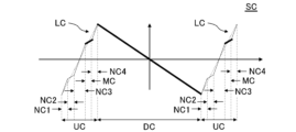
- FIG. 4 is a graph showing the vertical drive signal SC according to the third embodiment.
- the vertical drive signal SC according to the third embodiment is the same as the vertical drive signal SB according to the second embodiment except for the following points.
- the vertical drive signal SC according to the third embodiment changes periodically in the same manner as the vertical drive signal SB according to the second embodiment.
- Each period of the vertical drive signal SC according to the third embodiment includes a falling period DC and a rising period UC.
- the rising period UC according to the third embodiment includes a first non-irradiation period NC1, a second non-irradiation period NC2, a third non-irradiation period NC3, an irradiation period MC, and a fourth non-irradiation period NC4.
- the first non-irradiation period NC1, the second non-irradiation period NC2, the third non-irradiation period NC3, the irradiation period MC, and the fourth non-irradiation period NC4 are continuous in this order.
- a virtual line LC is attached to the rising period UC according to the third embodiment for the sake of explanation.
- the driving section 210 stops emitting the beam B from the movable reflecting section 120. Therefore, no spot S is generated in the first non-irradiation period NC1, the second non-irradiation period NC2, the third non-irradiation period NC3, and the fourth non-irradiation period NC4.
- the drive section 210 causes the light emitting element 110 to emit the beam B at a predetermined repetition period. Therefore, a plurality of spots S are generated along the scanning line L in the irradiation period MC.
- the irradiation period MC according to the third embodiment is a period during which the voltage value of the vertical drive signal SC is positive. Therefore, in the third embodiment, the density of the spots S above the positive direction in the second direction Y with respect to the center of the field of view F in the second direction Y can be increased compared to the first embodiment.
- the vertical drive signal SC in the third non-irradiation period NC3 has a predetermined first slope.
- the voltage value of the vertical drive signal SC switches from negative to positive in the third non-irradiation period NC3.
- the vertical drive signal SC in the irradiation period MC has a second slope different from the first slope. Specifically, the absolute value of the second slope is smaller than the absolute value of the first slope.
- the voltage value of the vertical drive signal SC in the irradiation period MC is positive.
- the vertical drive signal SC in the second non-irradiation period NC2 has a third slope different from the first slope. Specifically, the absolute value of the third slope is smaller than the absolute value of the first slope.
- the voltage value of the vertical drive signal SC in the second non-irradiation period NC2 is negative. Therefore, compared to the case where the vertical drive signal SC fluctuates along the line connecting the start of the first non-irradiation period NC1 and the start of the irradiation period MC, the positive DC component of the vertical drive signal SC can be reduced. can be done.
- the irradiation of the beam B to the movable reflector 120 during the rising period UC is not limited to the mode according to the third embodiment.
- the driving unit 210 emits the beam B at a predetermined repetition cycle. It may be emitted from the light emitting element 110 .
- FIG. 5 is a graph showing the vertical drive signal SD according to the fourth embodiment.
- the vertical drive signal SD according to the fourth embodiment is the same as the vertical drive signal SA according to the first embodiment except for the following points.
- the vertical drive signal SD according to the fourth embodiment changes periodically in the same manner as the vertical drive signal SA according to the first embodiment.
- Each period of the vertical drive signal SD according to the fourth embodiment includes a falling period DD and a rising period UD.
- the rising period UD according to the fourth embodiment includes a first non-irradiation period ND1, an irradiation period MD, and a first non-irradiation period ND2.
- a virtual line LD is attached to the rising period UD according to the fourth embodiment for the sake of explanation.
- the falling period DD includes a first falling period D1, a second falling period D2 and a third falling period D3.
- the first falling period D1, the second falling period D2 and the third falling period D3 are continuous in this order.
- the voltage value of the vertical drive signal SD is positive.
- the voltage value of the vertical drive signal SD switches from positive to negative.
- the third falling period D3 the voltage value of the vertical drive signal SD is negative.
- the slope of the vertical drive signal SD during part of the falling period DD is different from the slope of the vertical drive signal SD during the other part of the rising period UD.
- the absolute value of the slope of the vertical drive signal SD in the second falling period D2 is smaller than the absolute value of the slope of the vertical driving signal SD in the first falling period D1 and the third falling period D3. Therefore, compared to the case where the slope of the vertical drive signal SD in the falling period DD is constant throughout the falling period DD, the density of the spots S in the center of the field of view F in the second direction Y and its periphery is increased. be able to.
- the beam B emitted from the light emitting element 110 is a pulse beam emitted at a predetermined repetition period.
- the beam B emitted from the light emitting element 110 may be continuous light. Even when the beam B is continuous light, the density of the spots S at a desired position can be controlled to a desired density by driving the movable reflector 120 in the same manner as in the embodiment.
- Optical Device 110 Light Emitting Element 120 Movable Reflecting Part 130 Light Receiving Element 140 Beam Splitter 210 Driving Part 220 Signal Generating Part AX First Rotational Axis AY Second Rotating Axis B Beam D1 First Falling Period D2 Second Falling Period D3 Third Falling Period DA Falling period DB Falling period DC Falling period DD Falling period F Visual field IS Virtual plane L Scanning line LA Virtual line LB Virtual line LC Virtual line LD Virtual line MA Irradiation period MB Irradiation period MC Irradiation period MD Irradiation period NA1 First non-irradiation period NA2 Second non-irradiation period NB1 First non-irradiation period NB2 Second non-irradiation period NC1 First non-irradiation period NC2 Second non-irradiation period NC3 Third non-irradiation period NC4 Fourth non-irradiation period ND1 First non-irradiation period ND2 Second 1 non-irradiation period
Landscapes
- Physics & Mathematics (AREA)
- General Physics & Mathematics (AREA)
- Optics & Photonics (AREA)
- Engineering & Computer Science (AREA)
- Computer Networks & Wireless Communication (AREA)
- Radar, Positioning & Navigation (AREA)
- Remote Sensing (AREA)
- Electromagnetism (AREA)
- Optical Radar Systems And Details Thereof (AREA)
- Mechanical Optical Scanning Systems (AREA)
Priority Applications (6)
| Application Number | Priority Date | Filing Date | Title |
|---|---|---|---|
| EP22911083.8A EP4455760A4 (en) | 2021-12-21 | 2022-12-15 | OPTICAL DEVICE |
| JP2023569377A JPWO2023120375A1 (https=) | 2021-12-21 | 2022-12-15 | |
| US18/721,160 US20250060579A1 (en) | 2021-12-21 | 2022-12-15 | Optical device |
| CN202280084374.9A CN118414567A (zh) | 2021-12-21 | 2022-12-15 | 光学装置 |
| JP2025037556A JP2025083459A (ja) | 2021-12-21 | 2025-03-10 | 光学装置 |
| JP2025048980A JP2025085837A (ja) | 2021-12-21 | 2025-03-24 | 光学装置 |
Applications Claiming Priority (2)
| Application Number | Priority Date | Filing Date | Title |
|---|---|---|---|
| JP2021-206822 | 2021-12-21 | ||
| JP2021206822 | 2021-12-21 |
Publications (1)
| Publication Number | Publication Date |
|---|---|
| WO2023120375A1 true WO2023120375A1 (ja) | 2023-06-29 |
Family
ID=86902502
Family Applications (1)
| Application Number | Title | Priority Date | Filing Date |
|---|---|---|---|
| PCT/JP2022/046230 Ceased WO2023120375A1 (ja) | 2021-12-21 | 2022-12-15 | 光学装置 |
Country Status (5)
| Country | Link |
|---|---|
| US (1) | US20250060579A1 (https=) |
| EP (1) | EP4455760A4 (https=) |
| JP (3) | JPWO2023120375A1 (https=) |
| CN (1) | CN118414567A (https=) |
| WO (1) | WO2023120375A1 (https=) |
Citations (4)
| Publication number | Priority date | Publication date | Assignee | Title |
|---|---|---|---|---|
| JP2019095353A (ja) * | 2017-11-24 | 2019-06-20 | パイオニア株式会社 | 測距装置 |
| JP2019113457A (ja) * | 2017-12-25 | 2019-07-11 | パイオニア株式会社 | 走査装置及び測距装置 |
| WO2020004514A1 (ja) | 2018-06-26 | 2020-01-02 | ミツミ電機株式会社 | 回転往復駆動アクチュエータ |
| WO2021205647A1 (ja) * | 2020-04-10 | 2021-10-14 | 富士通株式会社 | 距離測定装置、画角制御方法、及びプログラム |
Family Cites Families (5)
| Publication number | Priority date | Publication date | Assignee | Title |
|---|---|---|---|---|
| US9986215B1 (en) * | 2017-03-23 | 2018-05-29 | Microsoft Technology Licensing, Llc | Laser scan beam foveated display |
| US11353559B2 (en) * | 2017-10-09 | 2022-06-07 | Luminar, Llc | Adjustable scan patterns for lidar system |
| US11415675B2 (en) * | 2017-10-09 | 2022-08-16 | Luminar, Llc | Lidar system with adjustable pulse period |
| US11391842B2 (en) * | 2020-01-06 | 2022-07-19 | Luminar, Llc | Adaptive scan pattern with virtual horizon estimation |
| JPWO2021245818A1 (https=) * | 2020-06-03 | 2021-12-09 |
-
2022
- 2022-12-15 WO PCT/JP2022/046230 patent/WO2023120375A1/ja not_active Ceased
- 2022-12-15 JP JP2023569377A patent/JPWO2023120375A1/ja active Pending
- 2022-12-15 EP EP22911083.8A patent/EP4455760A4/en active Pending
- 2022-12-15 CN CN202280084374.9A patent/CN118414567A/zh active Pending
- 2022-12-15 US US18/721,160 patent/US20250060579A1/en active Pending
-
2025
- 2025-03-10 JP JP2025037556A patent/JP2025083459A/ja active Pending
- 2025-03-24 JP JP2025048980A patent/JP2025085837A/ja active Pending
Patent Citations (4)
| Publication number | Priority date | Publication date | Assignee | Title |
|---|---|---|---|---|
| JP2019095353A (ja) * | 2017-11-24 | 2019-06-20 | パイオニア株式会社 | 測距装置 |
| JP2019113457A (ja) * | 2017-12-25 | 2019-07-11 | パイオニア株式会社 | 走査装置及び測距装置 |
| WO2020004514A1 (ja) | 2018-06-26 | 2020-01-02 | ミツミ電機株式会社 | 回転往復駆動アクチュエータ |
| WO2021205647A1 (ja) * | 2020-04-10 | 2021-10-14 | 富士通株式会社 | 距離測定装置、画角制御方法、及びプログラム |
Non-Patent Citations (1)
| Title |
|---|
| See also references of EP4455760A4 |
Also Published As
| Publication number | Publication date |
|---|---|
| JPWO2023120375A1 (https=) | 2023-06-29 |
| JP2025083459A (ja) | 2025-05-30 |
| EP4455760A1 (en) | 2024-10-30 |
| EP4455760A4 (en) | 2025-12-10 |
| CN118414567A (zh) | 2024-07-30 |
| JP2025085837A (ja) | 2025-06-05 |
| US20250060579A1 (en) | 2025-02-20 |
Similar Documents
| Publication | Publication Date | Title |
|---|---|---|
| JP6547942B2 (ja) | 半導体レーザ駆動装置、光走査装置、物体検出装置及び移動体装置 | |
| JP5654234B2 (ja) | X−y高速穴あけシステム | |
| JP5701636B2 (ja) | 干渉を抑えたレーザダイオード装置 | |
| JP2018511785A (ja) | 赤外線レーザ照明装置 | |
| JP6655377B2 (ja) | 光走査装置及び光走査方法 | |
| US10802270B2 (en) | Optical scanner comprising a calibrating unit to calibrate intensity of the drive signal applied to a mirror driving unit | |
| WO2021168849A1 (zh) | 激光雷达及激光雷达的扫描方法 | |
| KR20240033051A (ko) | 개별적으로 어드레스 가능하고 스캔 가능하며 통합 가능한 레이저 방출기를 갖는 라이다 | |
| JP6672055B2 (ja) | 超音波モータの制御方法及びそのための測量機 | |
| JP2005034859A (ja) | レーザ加工装置 | |
| WO2023120375A1 (ja) | 光学装置 | |
| JP2025113474A (ja) | 投光装置、測距装置、及びレーザ光の投光制御方法 | |
| TWI802917B (zh) | 雷射光路系統及雷射雷達 | |
| US11236988B2 (en) | Laser distance measuring apparatus | |
| JP2022121521A (ja) | 測距装置及び光走査装置 | |
| CN106526834A (zh) | 一种扫描反射镜及其扫描方法 | |
| US20210293954A1 (en) | Object detection apparatus and movable apparatus | |
| JP2019220270A (ja) | 光学ユニットおよび車両用前照灯 | |
| JP2023085576A (ja) | 測距装置 | |
| CN112368596A (zh) | 光测距装置 | |
| KR20240088268A (ko) | Fmcw 라이다의 광각 및 멀티채널 구현을 위한 광학 시스템 | |
| JP2019109143A (ja) | 光走査装置及び測距装置 | |
| JP2023076890A (ja) | 光出射装置および測定装置 | |
| WO2021192610A1 (ja) | センサ装置 | |
| JP2021012071A (ja) | 光走査装置、物体検出装置及びセンシング装置 |
Legal Events
| Date | Code | Title | Description |
|---|---|---|---|
| 121 | Ep: the epo has been informed by wipo that ep was designated in this application |
Ref document number: 22911083 Country of ref document: EP Kind code of ref document: A1 |
|
| WWE | Wipo information: entry into national phase |
Ref document number: 2023569377 Country of ref document: JP |
|
| WWE | Wipo information: entry into national phase |
Ref document number: 18721160 Country of ref document: US |
|
| WWE | Wipo information: entry into national phase |
Ref document number: 202280084374.9 Country of ref document: CN |
|
| NENP | Non-entry into the national phase |
Ref country code: DE |
|
| ENP | Entry into the national phase |
Ref document number: 2022911083 Country of ref document: EP Effective date: 20240722 |