WO2023120375A1 - Optical device - Google Patents
Optical device Download PDFInfo
- Publication number
- WO2023120375A1 WO2023120375A1 PCT/JP2022/046230 JP2022046230W WO2023120375A1 WO 2023120375 A1 WO2023120375 A1 WO 2023120375A1 JP 2022046230 W JP2022046230 W JP 2022046230W WO 2023120375 A1 WO2023120375 A1 WO 2023120375A1
- Authority
- WO
- WIPO (PCT)
- Prior art keywords
- period
- drive signal
- slope
- optical device
- vertical drive
- Prior art date
Links
- 230000003287 optical effect Effects 0.000 title claims description 31
- 230000007704 transition Effects 0.000 claims description 6
- 230000000630 rising effect Effects 0.000 description 32
- 238000010586 diagram Methods 0.000 description 3
- 240000001973 Ficus microcarpa Species 0.000 description 1
- 230000001174 ascending effect Effects 0.000 description 1
- 239000000470 constituent Substances 0.000 description 1
- 230000006378 damage Effects 0.000 description 1
- 238000001514 detection method Methods 0.000 description 1
- 230000020169 heat generation Effects 0.000 description 1
- 230000001678 irradiating effect Effects 0.000 description 1
- 238000005259 measurement Methods 0.000 description 1
- 230000000007 visual effect Effects 0.000 description 1
Images


Classifications
-
- G—PHYSICS
- G01—MEASURING; TESTING
- G01S—RADIO DIRECTION-FINDING; RADIO NAVIGATION; DETERMINING DISTANCE OR VELOCITY BY USE OF RADIO WAVES; LOCATING OR PRESENCE-DETECTING BY USE OF THE REFLECTION OR RERADIATION OF RADIO WAVES; ANALOGOUS ARRANGEMENTS USING OTHER WAVES
- G01S7/00—Details of systems according to groups G01S13/00, G01S15/00, G01S17/00
- G01S7/48—Details of systems according to groups G01S13/00, G01S15/00, G01S17/00 of systems according to group G01S17/00
- G01S7/481—Constructional features, e.g. arrangements of optical elements
-
- G—PHYSICS
- G02—OPTICS
- G02B—OPTICAL ELEMENTS, SYSTEMS OR APPARATUS
- G02B26/00—Optical devices or arrangements for the control of light using movable or deformable optical elements
- G02B26/08—Optical devices or arrangements for the control of light using movable or deformable optical elements for controlling the direction of light
- G02B26/10—Scanning systems
Definitions
- the present invention relates to optical devices.
- an optical device includes a movable reflector that reflects a beam emitted from a light emitting element such as a laser diode (LD).
- a spot is generated by irradiating the beam reflected by the movable reflector onto an object to be measured by the optical device.
- the irradiation position of the beam can be displaced in the horizontal direction by swinging the movable reflector around the predetermined first rotation axis. Further, by swinging the movable reflector around the second rotation axis perpendicular to the first rotation axis, the irradiation position of the beam can be displaced in the vertical direction.
- optical devices such as LiDAR
- One example of the problem to be solved by the present invention is controlling the density of spots at a desired position to a desired density.
- a signal generating unit for generating a drive signal for driving in a predetermined direction a movable reflecting unit that reflects the beam emitted from the light emitting element;
- the drive signal has a predetermined first slope without the beam being irradiated onto the movable reflecting portion. and a period in which the beam is applied to the movable reflector and the drive signal has a second slope different from the first slope.
- FIG. 1 is a diagram showing an optical device according to Embodiment 1;
- FIG. 5 is a graph showing vertical drive signals according to the first embodiment; 9 is a graph showing vertical drive signals according to the second embodiment; 10 is a graph showing vertical drive signals according to the third embodiment; 10 is a graph showing vertical drive signals according to Embodiment 4.
- FIG. 5 is a graph showing vertical drive signals according to the first embodiment; 9 is a graph showing vertical drive signals according to the second embodiment; 10 is a graph showing vertical drive signals according to the third embodiment; 10 is a graph showing vertical drive signals according to Embodiment 4.
- FIG. 5 is a graph showing vertical drive signals according to the first embodiment
- 9 is a graph showing vertical drive signals according to the second embodiment
- 10 is a graph showing vertical drive signals according to the third embodiment
- 10 is a graph showing vertical drive signals according to Embodiment 4.
- FIG. 5 is a graph showing vertical drive signals according to the first embodiment
- 9 is a graph showing vertical drive signals according to the second embodiment
- 10
- FIG. 1 is a diagram showing an optical device 10 according to Embodiment 1.
- FIG. 1 is a diagram showing an optical device 10 according to Embodiment 1.
- the arrows indicating the first direction X, the second direction Y, or the third direction Z indicate that the direction from the base end of the arrow to the tip is the positive direction of the direction indicated by the arrow, and the tip of the arrow to the proximal end is the negative direction of the direction indicated by the arrow.
- the first direction X is a direction parallel to the horizontal direction.
- the second direction Y is orthogonal to the first direction X.
- a second direction Y is a direction parallel to the vertical direction.
- the positive direction of the second direction Y is the direction from bottom to top in the vertical direction
- the negative direction of the second direction Y is the direction from top to bottom in the vertical direction.
- the third direction Z is orthogonal to both the first direction X and the second direction Y.
- a third direction Z is a direction parallel to the horizontal direction.
- the positive direction of the third direction Z is the direction from the side on which the movable reflecting portion 120 described later is located toward the side on which the virtual plane IS described later is located
- the negative direction of the third direction Z is the direction on which the virtual surface IS is located. It is the direction from the side where surface IS is located toward the side where movable reflecting section 120 is located.
- first direction X the first direction X
- second direction Y the third direction Z
- horizontal direction the vertical direction
- vertical direction the relationships between the first direction X, the second direction Y, the third direction Z, the horizontal direction, and the vertical direction are not limited to the examples described above.
- the relationships described above will change.
- the first direction X or the third direction Z may be parallel to the vertical direction.
- the optical device 10 includes a light emitting element 110 , a movable reflecting section 120 , a light receiving element 130 , a beam splitter 140 , a driving section 210 and a signal generating section 220 .
- the driving section 210 and the signal generating section 220 shown in FIG. 1 are functional block diagrams. Therefore, the driving unit 210 and the signal generating unit 220 shown in FIG. 1 do not suggest the actual size or the actual position of the driving unit 210 and the signal generating unit 220 .
- the light emitting element 110 is, for example, a laser diode (LD).
- the light emitting element 110 is driven by the driving section 210 .
- the drive unit 210 is, for example, a laser driver. Further, the drive unit 210 is controlled by a control unit such as a microcomputer (not shown).
- the light emitting element 110 emits the beam B at a predetermined repetition period. As indicated by the dashed line extending from the light emitting element 110 to the movable reflecting section 120 via the beam splitter 140 , the beam B is emitted from the light emitting element 110 , reflected by the beam splitter 140 , and then reflected by the movable reflecting section 120 . is irradiated.
- the movable reflector 120 is a MEMS (Micro Electro Mechanical Systems) mirror.
- the movable reflector 120 reflects the beam B toward the positive direction side of the third direction Z of the movable reflector 120 .
- the virtual surface IS exists on the positive side of the third direction Z of the movable reflecting section 120 .
- the virtual surface IS is provided virtually to explain the optical device 10 according to the first embodiment. Therefore, the virtual surface IS need not exist in the actual optical device 10 .
- the virtual plane IS is perpendicular to the third direction Z.
- the signal generator 220 inputs the horizontal drive signal and the vertical drive signal SA described later with reference to FIG. 2 to the movable reflector 120 .
- the signal generator 220 is, for example, an arbitrary signal generator.
- the horizontal drive signal drives the movable reflector 120 in the horizontal direction.
- the movable reflector 120 oscillates at the resonance frequency of the movable reflector 120 around the predetermined first rotation axis AX.
- the vertical driving signal SA drives the movable reflecting section 120 in the vertical direction.
- the movable reflector 120 oscillates around the second rotation axis AY orthogonal to the first rotation axis AX at a frequency having a fundamental frequency lower than the resonance frequency of the movable reflector 120 .
- the driving of the movable reflector 120 is not limited to this example.
- a field of view F shown in FIG. 1 indicates a field of view projected onto the virtual plane IS.
- the scanning line L exists within the field of view F projected onto the virtual plane IS.
- the beam B After being reflected by the movable reflector 120 , the beam B irradiates an object (not shown) located on the positive side of the third direction Z of the movable reflector 120 .
- the reflected light or scattered light of the beam B is applied to the movable reflector 120 as received light.
- the received light As indicated by the dashed line extending from the movable reflecting section 120 to the light receiving element 130 via the beam splitter 140, the received light is reflected by the movable reflecting section 120, passes through the beam splitter 140, and reaches the light receiving element 130. is irradiated. Thereby, the light receiving element 130 receives the received light.
- the light receiving element 130 is, for example, an avalanche photodiode (APD).
- the light receiving element 130 is electrically connected to a light receiving circuit (not shown).
- the light-receiving circuit generates a reception signal by receiving light received by the light-receiving element 130 .
- the optical device 10 includes a computer such as a microcomputer (not shown) electrically connected to the light receiving circuit.
- the computer measures the distance from the object irradiated with the beam B by measuring the time from when the beam B is emitted from the light emitting element 110 to when the received light is received by the light receiving element 130 .
- FIG. 2 is a graph showing the vertical drive signal SA according to the first embodiment.
- the horizontal axis of the graph shown in Fig. 2 indicates time.
- the arrow indicating the horizontal axis indicates that time elapses from the left proximal end of the arrow toward the right distal end of the arrow.
- the vertical axis of the graph shown in FIG. 2 indicates the voltage value of the vertical drive signal SA.
- the arrow indicating the vertical axis indicates that the voltage value increases from the base end on the lower side of the arrow to the tip on the upper side of the arrow.
- the voltage value of the vertical drive signal SA is 0 on the horizontal axis representing time.
- the position where the spot S is generated when the beam B is irradiated onto the movable reflector 120 shifts upward in the positive direction of the second direction Y of the field of view F.
- the voltage value of the vertical drive signal SA becomes smaller, the position where the spot S is generated when the beam B is irradiated onto the movable reflector 120 shifts downward in the negative direction of the second direction Y of the field of view F.
- the vertical drive signal SA changes periodically. Each period of the vertical drive signal SA includes a falling period DA and a rising period UA. The falling period DA and the rising period UA are alternately repeated. In the falling period DA, the vertical drive signal SA transitions from its maximum value to its minimum value. In the rising period UA, the vertical drive signal SA transitions from its minimum value to its maximum value.
- the falling period DA will be explained.
- the driving unit 210 causes the light emitting element 110 to emit the beam B at a predetermined repetition period throughout the falling period DA. Therefore, a plurality of spots S are generated along the scanning lines L over the entire second direction Y of the field of view F.
- FIG. Therefore, the falling period DA is a main range-finding period in which range-finding is performed in a wider range in the second direction Y of the field of view F than the range-finding in the rising period UA, which will be described later.
- the slope of the falling period DA is substantially constant throughout the falling period DA. Therefore, the density of the spots S in the second direction Y is substantially constant over the entire field of view F in the second direction Y during the falling period DA.
- a virtual line LA is attached to the rising period UA for the sake of explanation.
- a virtual line LA is a line segment connecting the minimum value of the vertical drive signal SA at the beginning of the rise period UA and the maximum value of the vertical drive signal SA at the end of the rise period UA.
- the slope of the virtual line LA is substantially constant throughout the rising period UA.
- the rising period UA includes a first non-irradiation period NA1, an irradiation period MA and a second non-irradiation period NA2.
- the first non-irradiation period NA1, the irradiation period MA, and the second non-irradiation period NA2 are continuous in this order.
- the driving section 210 stops emitting the beam B from the movable reflecting section 120.
- FIG. Therefore, no spot S is generated in the first non-irradiation period NA1 and the second non-irradiation period NA2.
- the driving section 210 causes the light emitting element 110 to emit the beam B at a predetermined repetition period. Therefore, a plurality of spots S are generated along the scanning line L during the irradiation period MA. Therefore, the ascending period UA is an auxiliary ranging period in which ranging is performed in a narrower range in the second direction Y of the field of view F than the ranging during the descending period DA.
- the irradiation period MA is a period during which the voltage value of the vertical drive signal SA switches from negative to positive and a period around it. Therefore, in the irradiation period MA, the spot S is generated at the center of the field of view F in the second direction Y and its periphery in the second direction Y. As shown in FIG. Therefore, the density of the spots S at the center of the field of view F in the second direction Y and its periphery in the second direction Y can be increased compared to the case where the spots S are not generated in the irradiation period MA.
- the slope of the vertical drive signal SA in the irradiation period MA is different from the slope of the vertical drive signal SA in the first non-irradiation period NA1 and the second non-irradiation period NA2.
- the absolute value of the slope of the vertical drive signal SA in the irradiation period MA is smaller than the absolute value of the slope of the vertical drive signal SA in the first non-irradiation period NA1 and the second non-irradiation period NA2.
- the positive and negative signs of the slope of the vertical drive signal SA are positive when the voltage value of the vertical drive signal SA increases as time elapses, and the voltage of the vertical drive signal SA increases as time elapses. It is negative when the value is small.
- the absolute value of the slope of the vertical drive signal SA during the irradiation period MA is smaller than the absolute value of the slope of the virtual line LA. Therefore, compared to the case where the absolute value of the slope of the vertical drive signal SA in the irradiation period MA is equal to or greater than the absolute value of the slope of the virtual line LA, the density of the spots S generated in the irradiation period MA in the second direction Y is reduced to can be higher.
- the absolute value of the slope of the vertical drive signal SA in the first non-irradiation period NA1 and the second non-irradiation period NA2 is preferably as large as possible under the constraints of the driving characteristics of the movable reflector 120.
- the absolute value of the slope of the vertical drive signal SA in the first non-irradiation period NA1 and the second non-irradiation period NA2 may be the maximum absolute value allowed under the constraints of the driving characteristics of the movable reflecting section 120.
- FIG. In this case, compared to the case where the vertical drive signal SA transitions with the slope of the maximum absolute value over the entire range from the minimum value to the maximum value, the density of the spots S at the desired position can be increased with a slight decrease in the frame rate. can be higher.
- the waveform of the vertical drive signal SA is not limited to the waveform according to the first embodiment.
- the absolute value of the slope of the vertical drive signal SA in the irradiation period MA may be larger than the absolute value of the slope of the vertical drive signal SA in the first non-irradiation period NA1 and the second non-irradiation period NA2.
- the rising period UA may include a period during which the slope of the vertical drive signal SA is 0 or negative.
- the slope of the vertical drive signal SA may be 0 or negative during at least part of at least one of the first non-irradiation period NA1, the irradiation period MA, and the second non-irradiation period NA2.
- the positive and negative signs of the slope of the vertical drive signal SA in at least one of the first non-irradiation period NA1, the irradiation period MA, and the second non-irradiation period NA2 and the vertical drive signal SA in the irradiation period MA
- the positive and negative signs of the slope may be reversed.
- the rising period UA is a predetermined first period.
- the beam B does not irradiate the movable reflecting section 120 and the vertical driving signal SA is not applied to the predetermined period.
- the irradiation period MA during the other partial period of the predetermined first period, the beam B is irradiated onto the movable reflecting section 120 and the vertical driving signal SA is tilted at a slope different from the first slope. It has a slope of 2.
- the falling period DA may be the predetermined first period.
- the beam B does not irradiate the movable reflecting section 120 and the vertical drive signal SA has a predetermined first slope.
- the beam B is applied to the movable reflecting section 120 and the vertical drive signal SA has a second slope different from the first slope.
- the movable reflecting section 120 may be irradiated with the beam B emitted from the light emitting element 110 at a predetermined repetition period throughout the entire rising period UA.
- the waveform control according to the first embodiment applies not only to the waveform of the drive signal that drives the movable reflector 120 in the vertical direction, but also to the waveform of the drive signal that drives the movable reflector 120 in a predetermined direction different from the vertical direction. Applicable.
- the waveform control according to the first embodiment is one of the waveform of the driving signal that drives the movable reflecting section 120 in the vertical direction and the waveform of the driving signal that drives the movable reflecting section 120 in a direction different from the vertical direction. Applicable to only or both.
- the irradiation of the beam B to the movable reflector 120 during the rising period UA is not limited to the mode according to the first embodiment.
- the driving unit 210 may cause the light emitting element 110 to emit the beam B at a predetermined repetition period.
- the irradiation of the beam B to the movable reflecting section 120 in the rising period UA may be performed not only during a single period of the irradiation period MA, but also during a plurality of divided periods.
- FIG. 3 is a graph showing the vertical drive signal SB according to the second embodiment.
- the vertical drive signal SB according to the second embodiment is the same as the vertical drive signal SA according to the first embodiment except for the following points.
- the vertical drive signal SB according to the second embodiment changes periodically in the same manner as the vertical drive signal SA according to the first embodiment.
- Each period of the vertical drive signal SB according to the second embodiment includes a falling period DB and a rising period UB.
- the rising period UB according to the second embodiment includes a first non-irradiation period NB1, an irradiation period MB, and a second non-irradiation period NB2.
- a virtual line LB is attached to the rising period UB according to the second embodiment for the sake of explanation.
- the irradiation period MB according to the second embodiment is a period during which the voltage value of the vertical drive signal SB is positive. Therefore, in the second embodiment, the density of the spots S above the center of the field of view F in the second direction Y in the positive direction can be increased compared to the first embodiment.
- the irradiation period MB may be a period during which the voltage value of the vertical drive signal SB is negative. In this case, compared to the first embodiment, the density of the spots S below the center of the field of view F in the second direction Y in the negative direction can be increased.
- the density of spots S at desired positions in the second direction Y in the field of view F can be controlled to a desired density according to the setting of the irradiation period.
- the generation position of the spot S during the rise period can be controlled according to the value of the vertical drive signal during the irradiation period. For example, if the irradiation period includes a period in which the voltage value of the vertical drive signal switches from negative to positive, the spot S in the rising period is generated in the center of the field of view F in the second direction Y and its periphery.
- the spot S in the rising period is positioned upward in the positive direction in the second direction Y with respect to the center of the field of view F in the second direction Y. generated. Furthermore, when the voltage value of the vertical drive signal is negative throughout the irradiation period, the spot S in the rising period is positioned downward in the negative direction in the second direction Y with respect to the center of the field of view F in the second direction Y. generated.
- the vertical drive signal SB in each period in Embodiment 2 contains a positive DC component.
- the DC component included in each cycle of the vertical drive signal SB is positive when the integrated value of each cycle of the vertical drive signal SB is positive, and is negative when the integrated value of each cycle of the vertical drive signal SB is negative. becomes.
- Steady flow of positive or negative direct current in the circuit forming the signal generating section 220 may cause heat generation or destruction of the circuit forming the signal generating section 220 . Therefore, it is desirable to avoid the constant flow of the DC component contained in the vertical drive signal SB.
- the vertical drive signal SB in a period different from the predetermined period shown in FIG. 3 may contain a negative DC component.
- the waveform of the vertical drive signal SB in a period different from the predetermined period may be modified from the waveform of the vertical drive signal SB in the predetermined period.
- the vertical drive signal SB in a period different from the predetermined period can contain a negative DC component.
- at least part of the positive DC component in the predetermined period can be canceled by the negative DC component in a period different from the predetermined period.
- the absolute value of the positive DC component in the predetermined period and the absolute value of the negative DC component in a period different from the predetermined period may be equal or different.
- the positive DC component in the predetermined period may be canceled by the negative DC component in one period different from the predetermined period, or the negative DC component in a plurality of periods different from the predetermined period. may be canceled by
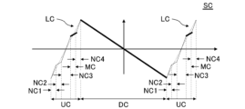
- FIG. 4 is a graph showing the vertical drive signal SC according to the third embodiment.
- the vertical drive signal SC according to the third embodiment is the same as the vertical drive signal SB according to the second embodiment except for the following points.
- the vertical drive signal SC according to the third embodiment changes periodically in the same manner as the vertical drive signal SB according to the second embodiment.
- Each period of the vertical drive signal SC according to the third embodiment includes a falling period DC and a rising period UC.
- the rising period UC according to the third embodiment includes a first non-irradiation period NC1, a second non-irradiation period NC2, a third non-irradiation period NC3, an irradiation period MC, and a fourth non-irradiation period NC4.
- the first non-irradiation period NC1, the second non-irradiation period NC2, the third non-irradiation period NC3, the irradiation period MC, and the fourth non-irradiation period NC4 are continuous in this order.
- a virtual line LC is attached to the rising period UC according to the third embodiment for the sake of explanation.
- the driving section 210 stops emitting the beam B from the movable reflecting section 120. Therefore, no spot S is generated in the first non-irradiation period NC1, the second non-irradiation period NC2, the third non-irradiation period NC3, and the fourth non-irradiation period NC4.
- the drive section 210 causes the light emitting element 110 to emit the beam B at a predetermined repetition period. Therefore, a plurality of spots S are generated along the scanning line L in the irradiation period MC.
- the irradiation period MC according to the third embodiment is a period during which the voltage value of the vertical drive signal SC is positive. Therefore, in the third embodiment, the density of the spots S above the positive direction in the second direction Y with respect to the center of the field of view F in the second direction Y can be increased compared to the first embodiment.
- the vertical drive signal SC in the third non-irradiation period NC3 has a predetermined first slope.
- the voltage value of the vertical drive signal SC switches from negative to positive in the third non-irradiation period NC3.
- the vertical drive signal SC in the irradiation period MC has a second slope different from the first slope. Specifically, the absolute value of the second slope is smaller than the absolute value of the first slope.
- the voltage value of the vertical drive signal SC in the irradiation period MC is positive.
- the vertical drive signal SC in the second non-irradiation period NC2 has a third slope different from the first slope. Specifically, the absolute value of the third slope is smaller than the absolute value of the first slope.
- the voltage value of the vertical drive signal SC in the second non-irradiation period NC2 is negative. Therefore, compared to the case where the vertical drive signal SC fluctuates along the line connecting the start of the first non-irradiation period NC1 and the start of the irradiation period MC, the positive DC component of the vertical drive signal SC can be reduced. can be done.
- the irradiation of the beam B to the movable reflector 120 during the rising period UC is not limited to the mode according to the third embodiment.
- the driving unit 210 emits the beam B at a predetermined repetition cycle. It may be emitted from the light emitting element 110 .
- FIG. 5 is a graph showing the vertical drive signal SD according to the fourth embodiment.
- the vertical drive signal SD according to the fourth embodiment is the same as the vertical drive signal SA according to the first embodiment except for the following points.
- the vertical drive signal SD according to the fourth embodiment changes periodically in the same manner as the vertical drive signal SA according to the first embodiment.
- Each period of the vertical drive signal SD according to the fourth embodiment includes a falling period DD and a rising period UD.
- the rising period UD according to the fourth embodiment includes a first non-irradiation period ND1, an irradiation period MD, and a first non-irradiation period ND2.
- a virtual line LD is attached to the rising period UD according to the fourth embodiment for the sake of explanation.
- the falling period DD includes a first falling period D1, a second falling period D2 and a third falling period D3.
- the first falling period D1, the second falling period D2 and the third falling period D3 are continuous in this order.
- the voltage value of the vertical drive signal SD is positive.
- the voltage value of the vertical drive signal SD switches from positive to negative.
- the third falling period D3 the voltage value of the vertical drive signal SD is negative.
- the slope of the vertical drive signal SD during part of the falling period DD is different from the slope of the vertical drive signal SD during the other part of the rising period UD.
- the absolute value of the slope of the vertical drive signal SD in the second falling period D2 is smaller than the absolute value of the slope of the vertical driving signal SD in the first falling period D1 and the third falling period D3. Therefore, compared to the case where the slope of the vertical drive signal SD in the falling period DD is constant throughout the falling period DD, the density of the spots S in the center of the field of view F in the second direction Y and its periphery is increased. be able to.
- the beam B emitted from the light emitting element 110 is a pulse beam emitted at a predetermined repetition period.
- the beam B emitted from the light emitting element 110 may be continuous light. Even when the beam B is continuous light, the density of the spots S at a desired position can be controlled to a desired density by driving the movable reflector 120 in the same manner as in the embodiment.
- Optical Device 110 Light Emitting Element 120 Movable Reflecting Part 130 Light Receiving Element 140 Beam Splitter 210 Driving Part 220 Signal Generating Part AX First Rotational Axis AY Second Rotating Axis B Beam D1 First Falling Period D2 Second Falling Period D3 Third Falling Period DA Falling period DB Falling period DC Falling period DD Falling period F Visual field IS Virtual plane L Scanning line LA Virtual line LB Virtual line LC Virtual line LD Virtual line MA Irradiation period MB Irradiation period MC Irradiation period MD Irradiation period NA1 First non-irradiation period NA2 Second non-irradiation period NB1 First non-irradiation period NB2 Second non-irradiation period NC1 First non-irradiation period NC2 Second non-irradiation period NC3 Third non-irradiation period NC4 Fourth non-irradiation period ND1 First non-irradiation period ND2 Second 1 non-irradiation period
Landscapes
- Physics & Mathematics (AREA)
- General Physics & Mathematics (AREA)
- Optics & Photonics (AREA)
- Engineering & Computer Science (AREA)
- Computer Networks & Wireless Communication (AREA)
- Radar, Positioning & Navigation (AREA)
- Remote Sensing (AREA)
- Optical Radar Systems And Details Thereof (AREA)
Abstract
An increase period UA is defined as a predetermined first period. As illustrated by a first non-irradiation period NA1 or a second non-irradiation period NA2, in a partial period of the predetermined first period, a movable reflection portion (120) is not irradiated with a beam B, and a vertical drive signal SA has a predetermined first inclination. Further, as illustrated by an irradiation period MA, in another partial period of the predetermined first period, the movable reflection portion (120) is irradiated with the beam B, and the vertical drive signal SA has a second inclination different from the first inclination.
Description
本発明は、光学装置に関する。
The present invention relates to optical devices.
近年、LiDAR(Light Detection And Ranging)等の様々な光学装置が開発されている。例えば特許文献1に記載されているように、光学装置は、レーザダイオード(LD)等の発光素子から照射されたビームを反射する可動反射部を備えている。可動反射部によって反射されたビームが光学装置の測距対象の物体に照射されることでスポットが生成される。所定の第1回転軸の周りに可動反射部を揺動させることで、ビームの照射位置を水平方向に変位させることができる。また、第1回転軸に直交する第2回転軸の周りに可動反射部を揺動させることで、ビームの照射位置を垂直方向に変位させることができる。
In recent years, various optical devices such as LiDAR (Light Detection And Ranging) have been developed. For example, as described in Patent Document 1, an optical device includes a movable reflector that reflects a beam emitted from a light emitting element such as a laser diode (LD). A spot is generated by irradiating the beam reflected by the movable reflector onto an object to be measured by the optical device. The irradiation position of the beam can be displaced in the horizontal direction by swinging the movable reflector around the predetermined first rotation axis. Further, by swinging the movable reflector around the second rotation axis perpendicular to the first rotation axis, the irradiation position of the beam can be displaced in the vertical direction.
LiDAR等の光学装置では、所望の位置におけるスポットの密度を所望の密度に制御することが要請されることがある。例えば、光学装置の視野の一部分のスポットの密度を当該一部分の周囲のスポットの密度よりも高くすることが要請されることがある。
In optical devices such as LiDAR, it is sometimes required to control the density of spots at desired positions to a desired density. For example, it may be desired to have a higher density of spots in a portion of the field of view of an optical device than the density of spots surrounding that portion.
本発明が解決しようとする課題としては、所望の位置におけるスポットの密度を所望の密度に制御することが一例として挙げられる。
One example of the problem to be solved by the present invention is controlling the density of spots at a desired position to a desired density.
請求項1に記載の発明は、
発光素子から照射されたビームを反射する可動反射部を所定方向に駆動する駆動信号を発生させる信号発生部を備え、
前記駆動信号が前記駆動信号の最大値及び最小値の一方から他方へ遷移する所定の第1期間が、前記ビームが前記可動反射部に照射されずに前記駆動信号が所定の第1の傾きを有する期間と、前記ビームが前記可動反射部に照射されて前記駆動信号が前記第1の傾きと異なる第2の傾きを有する期間と、を含む、光学装置である。 The invention according to claim 1,
a signal generating unit for generating a drive signal for driving in a predetermined direction a movable reflecting unit that reflects the beam emitted from the light emitting element;
During a predetermined first period in which the drive signal transitions from one of the maximum value and the minimum value of the drive signal to the other, the drive signal has a predetermined first slope without the beam being irradiated onto the movable reflecting portion. and a period in which the beam is applied to the movable reflector and the drive signal has a second slope different from the first slope.
以下、本発明の実施形態について、図面を用いて説明する。すべての図面において、同様な構成要素には同様の符号を付し、適宜説明を省略する。
Hereinafter, embodiments of the present invention will be described with reference to the drawings. In all the drawings, the same constituent elements are denoted by the same reference numerals, and the description thereof will be omitted as appropriate.
(実施形態1)
図1は、実施形態1に係る光学装置10を示す図である。 (Embodiment 1)
FIG. 1 is a diagram showing anoptical device 10 according to Embodiment 1. FIG.
図1は、実施形態1に係る光学装置10を示す図である。 (Embodiment 1)
FIG. 1 is a diagram showing an
図1において、第1方向X、第2方向Y又は第3方向Zを示す矢印は、当該矢印の基端から先端に向かう方向が当該矢印によって示される方向の正方向であり、当該矢印の先端から基端に向かう方向が当該矢印によって示される方向の負方向であることを示している。
In FIG. 1, the arrows indicating the first direction X, the second direction Y, or the third direction Z indicate that the direction from the base end of the arrow to the tip is the positive direction of the direction indicated by the arrow, and the tip of the arrow to the proximal end is the negative direction of the direction indicated by the arrow.
第1方向Xは、水平方向に平行な方向である。第2方向Yは、第1方向Xに直交している。第2方向Yは、垂直方向に平行な方向である。具体的には、第2方向Yの正方向は、垂直方向の下方から上方に向かう方向であり、第2方向Yの負方向は、垂直方向の上方から下方に向かう方向である。第3方向Zは、第1方向X及び第2方向Yの双方に直交している。第3方向Zは、水平方向に平行な方向である。具体的には、第3方向Zの正方向は、後述する可動反射部120が位置する側から後述する仮想面ISが位置する側に向かう方向であり、第3方向Zの負方向は、仮想面ISが位置する側から可動反射部120が位置する側に向かう方向である。
The first direction X is a direction parallel to the horizontal direction. The second direction Y is orthogonal to the first direction X. As shown in FIG. A second direction Y is a direction parallel to the vertical direction. Specifically, the positive direction of the second direction Y is the direction from bottom to top in the vertical direction, and the negative direction of the second direction Y is the direction from top to bottom in the vertical direction. The third direction Z is orthogonal to both the first direction X and the second direction Y. As shown in FIG. A third direction Z is a direction parallel to the horizontal direction. Specifically, the positive direction of the third direction Z is the direction from the side on which the movable reflecting portion 120 described later is located toward the side on which the virtual plane IS described later is located, and the negative direction of the third direction Z is the direction on which the virtual surface IS is located. It is the direction from the side where surface IS is located toward the side where movable reflecting section 120 is located.
なお、第1方向X、第2方向Y、第3方向Z、水平方向及び垂直方向の関係は、上述した例に限定されない。水平方向及び垂直方向に対する光学装置10の配置に応じて、上述した関係は変化する。例えば、第1方向X又は第3方向Zが垂直方向に平行になっていてもよい。
Note that the relationships between the first direction X, the second direction Y, the third direction Z, the horizontal direction, and the vertical direction are not limited to the examples described above. Depending on the orientation of the optical device 10 with respect to the horizontal and vertical directions, the relationships described above will change. For example, the first direction X or the third direction Z may be parallel to the vertical direction.
光学装置10は、発光素子110、可動反射部120、受光素子130、ビームスプリッタ140、駆動部210及び信号発生部220を備えている。図1に示す駆動部210及び信号発生部220は、機能ブロック図である。したがって、図1に示す駆動部210及び信号発生部220は、駆動部210及び信号発生部220の実際の大きさや実際の位置を示唆するものではない。
The optical device 10 includes a light emitting element 110 , a movable reflecting section 120 , a light receiving element 130 , a beam splitter 140 , a driving section 210 and a signal generating section 220 . The driving section 210 and the signal generating section 220 shown in FIG. 1 are functional block diagrams. Therefore, the driving unit 210 and the signal generating unit 220 shown in FIG. 1 do not suggest the actual size or the actual position of the driving unit 210 and the signal generating unit 220 .
発光素子110は、例えばレーザダイオード(LD)である。発光素子110は、駆動部210によって駆動されている。駆動部210は、例えばレーザドライバである。また、駆動部210は、不図示のマイクロコンピュータ等の制御部によって制御されている。発光素子110は、所定の繰り返し周期でビームBを出射している。発光素子110からビームスプリッタ140を経由して可動反射部120に向けて延びる破線で示されるように、ビームBは、発光素子110から出射されて、ビームスプリッタ140によって反射されて、可動反射部120に照射されている。
The light emitting element 110 is, for example, a laser diode (LD). The light emitting element 110 is driven by the driving section 210 . The drive unit 210 is, for example, a laser driver. Further, the drive unit 210 is controlled by a control unit such as a microcomputer (not shown). The light emitting element 110 emits the beam B at a predetermined repetition period. As indicated by the dashed line extending from the light emitting element 110 to the movable reflecting section 120 via the beam splitter 140 , the beam B is emitted from the light emitting element 110 , reflected by the beam splitter 140 , and then reflected by the movable reflecting section 120 . is irradiated.
実施形態1において、可動反射部120は、MEMS(Micro Electro Mechanical Systems)ミラーである。可動反射部120は、ビームBを可動反射部120の第3方向Zの正方向側に向けて反射している。図1に示す例では、可動反射部120の第3方向Zの正方向側に仮想面ISが存在している。仮想面ISは、実施形態1に係る光学装置10を説明するために仮想的に設けられたものである。このため、実際の光学装置10において仮想面ISが存在する必要はない。仮想面ISは、第3方向Zに垂直になっている。図1において可動反射部120から仮想面ISにかけて延びる破線で示されるようにビームBが仮想面ISに照射された場合、仮想面ISにスポットSが生成される。
In Embodiment 1, the movable reflector 120 is a MEMS (Micro Electro Mechanical Systems) mirror. The movable reflector 120 reflects the beam B toward the positive direction side of the third direction Z of the movable reflector 120 . In the example shown in FIG. 1, the virtual surface IS exists on the positive side of the third direction Z of the movable reflecting section 120 . The virtual surface IS is provided virtually to explain the optical device 10 according to the first embodiment. Therefore, the virtual surface IS need not exist in the actual optical device 10 . The virtual plane IS is perpendicular to the third direction Z. When the beam B is irradiated onto the virtual surface IS as indicated by the dashed line extending from the movable reflector 120 to the virtual surface IS in FIG. 1, a spot S is generated on the virtual surface IS.
信号発生部220は、水平駆動信号と、図2を用いて後述する垂直駆動信号SAと、を可動反射部120に入力している。信号発生部220は、例えば任意信号発生器である。一例において、水平駆動信号によって、可動反射部120は、水平方向に駆動されている。具体的には、可動反射部120は、所定の第1回転軸AXの周りに可動反射部120の共振周波数で揺動している。また、垂直駆動信号SAによって、可動反射部120は、垂直方向に駆動されている。具体的には、可動反射部120は、第1回転軸AXに直交する第2回転軸AYの周りに可動反射部120の共振周波数より低い基本周波数を有する周波数で揺動している。ただし、可動反射部120の駆動は、この例に限定されない。
The signal generator 220 inputs the horizontal drive signal and the vertical drive signal SA described later with reference to FIG. 2 to the movable reflector 120 . The signal generator 220 is, for example, an arbitrary signal generator. In one example, the horizontal drive signal drives the movable reflector 120 in the horizontal direction. Specifically, the movable reflector 120 oscillates at the resonance frequency of the movable reflector 120 around the predetermined first rotation axis AX. The vertical driving signal SA drives the movable reflecting section 120 in the vertical direction. Specifically, the movable reflector 120 oscillates around the second rotation axis AY orthogonal to the first rotation axis AX at a frequency having a fundamental frequency lower than the resonance frequency of the movable reflector 120 . However, the driving of the movable reflector 120 is not limited to this example.
発光素子110から所定の繰り返し周期でビームBが出射されている場合、可動反射部120の第1回転軸AXの周りの揺動及び可動反射部120の第2回転軸AYの周りの揺動によって、複数のスポットSが走査線Lに沿って生成される。これによって、視野Fにおける物体の測距を行うことができる。図1に示す視野Fは、仮想面ISに投影された視野を示している。走査線Lは、仮想面ISに投影された視野F内に存在している。
When the beam B is emitted from the light emitting element 110 at a predetermined repetition period, the swinging of the movable reflecting section 120 about the first rotation axis AX and the swinging of the movable reflecting section 120 about the second rotation axis AY cause , a plurality of spots S are generated along the scan line L. FIG. Thereby, distance measurement of an object in the field of view F can be performed. A field of view F shown in FIG. 1 indicates a field of view projected onto the virtual plane IS. The scanning line L exists within the field of view F projected onto the virtual plane IS.
ビームBは、可動反射部120によって反射された後、可動反射部120の第3方向Zの正方向側に位置する不図示の物体に照射されている。ビームBが当該物体によって反射又は散乱された場合、ビームBの反射光又は散乱光は、受信光として可動反射部120に照射される。可動反射部120からビームスプリッタ140を経由して受光素子130に向けて延びる破線で示されるように、受信光は、可動反射部120によって反射されて、ビームスプリッタ140を透過して、受光素子130に照射されている。これによって、受光素子130は、受信光を受信している。受光素子130は、例えば、アバランシェフォトダイオード(APD)である。例えば、受光素子130は、不図示の受光回路に電気的に接続されている。受光回路は、受光素子130による受信光の受信によって受信信号を生成する。光学装置10は、受光回路に電気的に接続された不図示のマイクロコンピュータ等のコンピュータを備えている。コンピュータは、発光素子110からビームBが出射されてから受光素子130によって受信光が受信されるまでの時間を測定することで、ビームBが照射された物体の測距を行っている。
After being reflected by the movable reflector 120 , the beam B irradiates an object (not shown) located on the positive side of the third direction Z of the movable reflector 120 . When the beam B is reflected or scattered by the object, the reflected light or scattered light of the beam B is applied to the movable reflector 120 as received light. As indicated by the dashed line extending from the movable reflecting section 120 to the light receiving element 130 via the beam splitter 140, the received light is reflected by the movable reflecting section 120, passes through the beam splitter 140, and reaches the light receiving element 130. is irradiated. Thereby, the light receiving element 130 receives the received light. The light receiving element 130 is, for example, an avalanche photodiode (APD). For example, the light receiving element 130 is electrically connected to a light receiving circuit (not shown). The light-receiving circuit generates a reception signal by receiving light received by the light-receiving element 130 . The optical device 10 includes a computer such as a microcomputer (not shown) electrically connected to the light receiving circuit. The computer measures the distance from the object irradiated with the beam B by measuring the time from when the beam B is emitted from the light emitting element 110 to when the received light is received by the light receiving element 130 .
図2は、実施形態1に係る垂直駆動信号SAを示すグラフである。
FIG. 2 is a graph showing the vertical drive signal SA according to the first embodiment.
図2に示すグラフの横軸は、時間を示している。横軸を示す矢印は、当該矢印の左側の基端から当該矢印の右側の先端に向かうにつれて時間が経過していることを示している。
The horizontal axis of the graph shown in Fig. 2 indicates time. The arrow indicating the horizontal axis indicates that time elapses from the left proximal end of the arrow toward the right distal end of the arrow.
図2に示すグラフの縦軸は、垂直駆動信号SAの電圧値を示している。縦軸を示す矢印は、当該矢印の下側の基端から当該矢印の上側の先端に向かうにつれて電圧値が高くなっていることを示している。垂直駆動信号SAの電圧値は、時間を示す上記横軸において0となっている。垂直駆動信号SAの電圧値が0である場合において可動反射部120にビームBが照射されたとき、スポットSは、視野Fの第2方向Yのほぼ中心に生成される。垂直駆動信号SAの電圧値が大きくなるほど、可動反射部120にビームBが照射されたときのスポットSの生成位置が視野Fの第2方向Yの正方向の上方に向けて変位する。垂直駆動信号SAの電圧値が小さくなるほど、可動反射部120にビームBが照射されたときのスポットSの生成位置が視野Fの第2方向Yの負方向の下方に向けて変位する。
The vertical axis of the graph shown in FIG. 2 indicates the voltage value of the vertical drive signal SA. The arrow indicating the vertical axis indicates that the voltage value increases from the base end on the lower side of the arrow to the tip on the upper side of the arrow. The voltage value of the vertical drive signal SA is 0 on the horizontal axis representing time. When the beam B irradiates the movable reflector 120 when the voltage value of the vertical drive signal SA is 0, the spot S is generated substantially at the center of the field of view F in the second direction Y. FIG. As the voltage value of the vertical drive signal SA increases, the position where the spot S is generated when the beam B is irradiated onto the movable reflector 120 shifts upward in the positive direction of the second direction Y of the field of view F. As the voltage value of the vertical drive signal SA becomes smaller, the position where the spot S is generated when the beam B is irradiated onto the movable reflector 120 shifts downward in the negative direction of the second direction Y of the field of view F.
垂直駆動信号SAは、周期的に変化している。垂直駆動信号SAの各周期は、下降期間DA及び上昇期間UA及を含んでいる。下降期間DA及び上昇期間UAは、交互に繰り返されている。下降期間DAにおいて、垂直駆動信号SAは、垂直駆動信号SAの最大値から最小値へ遷移している。上昇期間UAにおいて、垂直駆動信号SAは、垂直駆動信号SAの最小値から最大値へ遷移している。
The vertical drive signal SA changes periodically. Each period of the vertical drive signal SA includes a falling period DA and a rising period UA. The falling period DA and the rising period UA are alternately repeated. In the falling period DA, the vertical drive signal SA transitions from its maximum value to its minimum value. In the rising period UA, the vertical drive signal SA transitions from its minimum value to its maximum value.
下降期間DAについて説明する。
The falling period DA will be explained.
下降期間DAの全体に亘って、駆動部210は、所定の繰り返し周期でビームBを発光素子110から出射させている。このため、複数のスポットSが走査線Lに沿って視野Fの第2方向Yの全体に亘って生成されている。したがって、下降期間DAは、後述する上昇期間UAにおける測距よりも視野Fの第2方向Yの広い範囲で測距が行われる主測距期間となっている。
The driving unit 210 causes the light emitting element 110 to emit the beam B at a predetermined repetition period throughout the falling period DA. Therefore, a plurality of spots S are generated along the scanning lines L over the entire second direction Y of the field of view F. FIG. Therefore, the falling period DA is a main range-finding period in which range-finding is performed in a wider range in the second direction Y of the field of view F than the range-finding in the rising period UA, which will be described later.
下降期間DAの傾きは、下降期間DAの全体に亘って実質的に一定となっている。したがって、下降期間DAにおいては、スポットSの第2方向Yの密度が視野Fの第2方向Yの全体に亘って実質的に一定となっている。
The slope of the falling period DA is substantially constant throughout the falling period DA. Therefore, the density of the spots S in the second direction Y is substantially constant over the entire field of view F in the second direction Y during the falling period DA.
上昇期間UAについて説明する。
I will explain the rising period UA.
図2に示す例では、説明のため、上昇期間UAに仮想線LAが付されている。仮想線LAは、上昇期間UAの始期における垂直駆動信号SAの最小値と、上昇期間UAの終期における垂直駆動信号SAの最大値と、を結ぶ線分である。仮想線LAの傾きは、上昇期間UAの全体に亘って実質的に一定となっている。
In the example shown in FIG. 2, a virtual line LA is attached to the rising period UA for the sake of explanation. A virtual line LA is a line segment connecting the minimum value of the vertical drive signal SA at the beginning of the rise period UA and the maximum value of the vertical drive signal SA at the end of the rise period UA. The slope of the virtual line LA is substantially constant throughout the rising period UA.
上昇期間UAは、第1非照射期間NA1、照射期間MA及び第2非照射期間NA2を含んでいる。第1非照射期間NA1、照射期間MA及び第2非照射期間NA2は、順に連続している。
The rising period UA includes a first non-irradiation period NA1, an irradiation period MA and a second non-irradiation period NA2. The first non-irradiation period NA1, the irradiation period MA, and the second non-irradiation period NA2 are continuous in this order.
第1非照射期間NA1及び第2非照射期間NA2において、駆動部210は、可動反射部120からのビームBの出射を停止している。このため、第1非照射期間NA1及び第2非照射期間NA2では、スポットSが生成されていない。これに対して、照射期間MAにおいて、駆動部210は、所定の繰り返し周期でビームBを発光素子110から出射させている。このため、照射期間MAでは、複数のスポットSが走査線Lに沿って生成されている。したがって、上昇期間UAは、下降期間DAにおける測距よりも視野Fの第2方向Yの狭い範囲で測距が行われる副測距期間となっている。
In the first non-irradiation period NA1 and the second non-irradiation period NA2, the driving section 210 stops emitting the beam B from the movable reflecting section 120. FIG. Therefore, no spot S is generated in the first non-irradiation period NA1 and the second non-irradiation period NA2. On the other hand, in the irradiation period MA, the driving section 210 causes the light emitting element 110 to emit the beam B at a predetermined repetition period. Therefore, a plurality of spots S are generated along the scanning line L during the irradiation period MA. Therefore, the ascending period UA is an auxiliary ranging period in which ranging is performed in a narrower range in the second direction Y of the field of view F than the ranging during the descending period DA.
実施形態1に係る照射期間MAは、垂直駆動信号SAの電圧値が負から正に切り替わる期間及びその周辺の期間となっている。したがって、照射期間MAにおいては、視野Fの第2方向Yの中心及びその第2方向Yの周辺においてスポットSが生成されている。このため、照射期間MAにおいてスポットSが生成されない場合と比較して、視野Fの第2方向Yの中心及びその第2方向Yの周辺におけるスポットSの密度を高くすることができる。
The irradiation period MA according to the first embodiment is a period during which the voltage value of the vertical drive signal SA switches from negative to positive and a period around it. Therefore, in the irradiation period MA, the spot S is generated at the center of the field of view F in the second direction Y and its periphery in the second direction Y. As shown in FIG. Therefore, the density of the spots S at the center of the field of view F in the second direction Y and its periphery in the second direction Y can be increased compared to the case where the spots S are not generated in the irradiation period MA.
実施形態1において、照射期間MAにおける垂直駆動信号SAの傾きは、第1非照射期間NA1及び第2非照射期間NA2における垂直駆動信号SAの傾きと異なっている。具体的には、照射期間MAにおける垂直駆動信号SAの傾きの絶対値は、第1非照射期間NA1及び第2非照射期間NA2における垂直駆動信号SAの傾きの絶対値より小さくなっている。なお、垂直駆動信号SAの傾きの正及び負の符号は、時間が経過するにつれて垂直駆動信号SAの電圧値が大きくなる場合に正となっており、時間が経過するにつれて垂直駆動信号SAの電圧値が小さくなる場合に負となっている。
In Embodiment 1, the slope of the vertical drive signal SA in the irradiation period MA is different from the slope of the vertical drive signal SA in the first non-irradiation period NA1 and the second non-irradiation period NA2. Specifically, the absolute value of the slope of the vertical drive signal SA in the irradiation period MA is smaller than the absolute value of the slope of the vertical drive signal SA in the first non-irradiation period NA1 and the second non-irradiation period NA2. The positive and negative signs of the slope of the vertical drive signal SA are positive when the voltage value of the vertical drive signal SA increases as time elapses, and the voltage of the vertical drive signal SA increases as time elapses. It is negative when the value is small.
実施形態1において、照射期間MAにおける垂直駆動信号SAの傾きの絶対値は、仮想線LAの傾きの絶対値より小さくなっている。したがって、照射期間MAにおける垂直駆動信号SAの傾きの絶対値が仮想線LAの傾きの絶対値以上である場合と比較して、照射期間MAに生成されるスポットSの第2方向Yの密度をより高くすることができる。
In Embodiment 1, the absolute value of the slope of the vertical drive signal SA during the irradiation period MA is smaller than the absolute value of the slope of the virtual line LA. Therefore, compared to the case where the absolute value of the slope of the vertical drive signal SA in the irradiation period MA is equal to or greater than the absolute value of the slope of the virtual line LA, the density of the spots S generated in the irradiation period MA in the second direction Y is reduced to can be higher.
実施形態1において、第1非照射期間NA1及び第2非照射期間NA2における垂直駆動信号SAの傾きの絶対値は、可動反射部120の駆動特性の制約下において、可能な限り大きいことが好ましい。例えば、第1非照射期間NA1及び第2非照射期間NA2における垂直駆動信号SAの傾きの絶対値は、可動反射部120の駆動特性の制約下において許容される最大の絶対値にしてもよい。この場合、垂直駆動信号SAが最小値から最大値にかけての全範囲で当該最大の絶対値の傾きで遷移する場合と比較して、僅かなフレームレートの低下で所望の位置におけるスポットSの密度を高くすることができる。
In Embodiment 1, the absolute value of the slope of the vertical drive signal SA in the first non-irradiation period NA1 and the second non-irradiation period NA2 is preferably as large as possible under the constraints of the driving characteristics of the movable reflector 120. For example, the absolute value of the slope of the vertical drive signal SA in the first non-irradiation period NA1 and the second non-irradiation period NA2 may be the maximum absolute value allowed under the constraints of the driving characteristics of the movable reflecting section 120. FIG. In this case, compared to the case where the vertical drive signal SA transitions with the slope of the maximum absolute value over the entire range from the minimum value to the maximum value, the density of the spots S at the desired position can be increased with a slight decrease in the frame rate. can be higher.
垂直駆動信号SAの波形は、実施形態1に係る波形に限定されない。
The waveform of the vertical drive signal SA is not limited to the waveform according to the first embodiment.
例えば、照射期間MAにおける垂直駆動信号SAの傾きの絶対値は、第1非照射期間NA1及び第2非照射期間NA2における垂直駆動信号SAの傾きの絶対値より大きくてもよい。
For example, the absolute value of the slope of the vertical drive signal SA in the irradiation period MA may be larger than the absolute value of the slope of the vertical drive signal SA in the first non-irradiation period NA1 and the second non-irradiation period NA2.
また、上昇期間UAは、垂直駆動信号SAの傾きが0又は負となる期間を含んでいてもよい。例えば、第1非照射期間NA1、照射期間MA及び第2非照射期間NA2の少なくとも1つの少なくとも一部の期間において、垂直駆動信号SAの傾きが0又は負となっていてもよい。これによって、例えば、第1非照射期間NA1、照射期間MA及び第2非照射期間NA2の少なくとも1つにおける垂直駆動信号SAの傾きの正及び負の符号と、照射期間MAにおける垂直駆動信号SAの傾きの正及び負の符号と、が反転していてもよい。
Also, the rising period UA may include a period during which the slope of the vertical drive signal SA is 0 or negative. For example, the slope of the vertical drive signal SA may be 0 or negative during at least part of at least one of the first non-irradiation period NA1, the irradiation period MA, and the second non-irradiation period NA2. As a result, for example, the positive and negative signs of the slope of the vertical drive signal SA in at least one of the first non-irradiation period NA1, the irradiation period MA, and the second non-irradiation period NA2, and the vertical drive signal SA in the irradiation period MA The positive and negative signs of the slope may be reversed.
また、実施形態1において、上昇期間UAは、所定の第1期間となっている。第1非照射期間NA1又は第2非照射期間NA2によって例示されるように、所定の第1期間の一部の期間では、ビームBが可動反射部120に照射されずに垂直駆動信号SAが所定の第1の傾きを有している。また、照射期間MAによって例示されるように、所定の第1期間の他の一部の期間では、ビームBが可動反射部120に照射されて垂直駆動信号SAが当該第1の傾きと異なる第2の傾きを有している。しかしながら、下降期間DAが所定の第1期間となっていてもよい。この例においては、下降期間DAの一部の期間において、ビームBが可動反射部120に照射されずに垂直駆動信号SAが所定の第1の傾きを有している。また、下降期間DAの他の一部の期間において、ビームBが可動反射部120に照射されて垂直駆動信号SAが当該第1の傾きと異なる第2の傾きを有している。この例では、上昇期間UAの全体に亘って、発光素子110から所定の繰り返し周期で出射されたビームBが可動反射部120に照射されていてもよい。
Also, in the first embodiment, the rising period UA is a predetermined first period. As exemplified by the first non-irradiation period NA1 or the second non-irradiation period NA2, during a part of the predetermined first period, the beam B does not irradiate the movable reflecting section 120 and the vertical driving signal SA is not applied to the predetermined period. has a first slope of Further, as exemplified by the irradiation period MA, during the other partial period of the predetermined first period, the beam B is irradiated onto the movable reflecting section 120 and the vertical driving signal SA is tilted at a slope different from the first slope. It has a slope of 2. However, the falling period DA may be the predetermined first period. In this example, during a part of the falling period DA, the beam B does not irradiate the movable reflecting section 120 and the vertical drive signal SA has a predetermined first slope. Also, during another partial period of the falling period DA, the beam B is applied to the movable reflecting section 120 and the vertical drive signal SA has a second slope different from the first slope. In this example, the movable reflecting section 120 may be irradiated with the beam B emitted from the light emitting element 110 at a predetermined repetition period throughout the entire rising period UA.
実施形態1では、垂直駆動信号SAによって例示されるように、可動反射部120を垂直方向に駆動させる駆動信号の波形の制御について説明した。しかしながら、実施形態1に係る波形の制御は、可動反射部120を垂直方向に駆動させる駆動信号の波形だけでなく、可動反射部120を垂直方向と異なる所定方向に駆動させる駆動信号の波形にも適用可能である。この場合、実施形態1に係る波形の制御は、可動反射部120を垂直方向に駆動させる駆動信号の波形と、可動反射部120を垂直方向と異なる方向に駆動させる駆動信号の波形と、の一方のみ又は双方に適用可能である。
In the first embodiment, as exemplified by the vertical drive signal SA, control of the waveform of the drive signal that drives the movable reflector 120 in the vertical direction has been described. However, the waveform control according to the first embodiment applies not only to the waveform of the drive signal that drives the movable reflector 120 in the vertical direction, but also to the waveform of the drive signal that drives the movable reflector 120 in a predetermined direction different from the vertical direction. Applicable. In this case, the waveform control according to the first embodiment is one of the waveform of the driving signal that drives the movable reflecting section 120 in the vertical direction and the waveform of the driving signal that drives the movable reflecting section 120 in a direction different from the vertical direction. Applicable to only or both.
また、上昇期間UAにおける可動反射部120へのビームBの照射は、実施形態1に係る態様に限定されない。例えば、照射期間MAだけでなく、第1非照射期間NA1及び第2非照射期間NA2の少なくとも一方においても、駆動部210は、所定の繰り返し周期でビームBを発光素子110から出射させてもよい。また、上昇期間UAにおける可動反射部120へのビームBの照射は、照射期間MAの単一の期間だけでなく、分割された複数の期間に行われていてもよい。
Also, the irradiation of the beam B to the movable reflector 120 during the rising period UA is not limited to the mode according to the first embodiment. For example, in at least one of the first non-irradiation period NA1 and the second non-irradiation period NA2 as well as the irradiation period MA, the driving unit 210 may cause the light emitting element 110 to emit the beam B at a predetermined repetition period. . Further, the irradiation of the beam B to the movable reflecting section 120 in the rising period UA may be performed not only during a single period of the irradiation period MA, but also during a plurality of divided periods.
(実施形態2)
図3は、実施形態2に係る垂直駆動信号SBを示すグラフである。実施形態2に係る垂直駆動信号SBは、以下の点を除いて、実施形態1に係る垂直駆動信号SAと同様である。 (Embodiment 2)
FIG. 3 is a graph showing the vertical drive signal SB according to the second embodiment. The vertical drive signal SB according to the second embodiment is the same as the vertical drive signal SA according to the first embodiment except for the following points.
実施形態2に係る垂直駆動信号SBは、実施形態1に係る垂直駆動信号SAと同様にして、周期的に変化している。実施形態2に係る垂直駆動信号SBの各周期は、下降期間DB及び上昇期間UBを含んでいる。実施形態2に係る上昇期間UBは、第1非照射期間NB1、照射期間MB及び第2非照射期間NB2を含んでいる。また、実施形態2に係る上昇期間UBには、説明のため、仮想線LBが付されている。
The vertical drive signal SB according to the second embodiment changes periodically in the same manner as the vertical drive signal SA according to the first embodiment. Each period of the vertical drive signal SB according to the second embodiment includes a falling period DB and a rising period UB. The rising period UB according to the second embodiment includes a first non-irradiation period NB1, an irradiation period MB, and a second non-irradiation period NB2. A virtual line LB is attached to the rising period UB according to the second embodiment for the sake of explanation.
実施形態2に係る照射期間MBは、垂直駆動信号SBの電圧値が正の期間となっている。したがって、実施形態2においては、実施形態1と比較して、視野Fの第2方向Yの中心に対して第2方向Yの正方向の上方におけるスポットSの密度を高くすることができる。照射期間MBは、垂直駆動信号SBの電圧値が負の期間となっていてもよい。この場合、実施形態1と比較して、視野Fの第2方向Yの中心に対して第2方向Yの負方向の下方におけるスポットSの密度を高くすることができる。
The irradiation period MB according to the second embodiment is a period during which the voltage value of the vertical drive signal SB is positive. Therefore, in the second embodiment, the density of the spots S above the center of the field of view F in the second direction Y in the positive direction can be increased compared to the first embodiment. The irradiation period MB may be a period during which the voltage value of the vertical drive signal SB is negative. In this case, compared to the first embodiment, the density of the spots S below the center of the field of view F in the second direction Y in the negative direction can be increased.
実施形態1及び実施形態2の説明より、照射期間の設定に応じて、視野Fの第2方向Yの所望の位置におけるスポットSの密度を所望の密度に制御することができる。具体的には、照射期間における垂直駆動信号の値に応じて、上昇期間におけるスポットSの生成位置を制御することができる。例えば、垂直駆動信号の電圧値が負から正に切り替る期間を照射期間が含む場合、上昇期間におけるスポットSは、視野Fの第2方向Yの中心及びその周辺に生成される。また、照射期間の全体に亘って垂直駆動信号の電圧値が正である場合、上昇期間におけるスポットSは、視野Fの第2方向Yの中心に対して第2方向Yの正方向の上方に生成される。さらに、照射期間の全体に亘って垂直駆動信号の電圧値が負である場合、上昇期間におけるスポットSは、視野Fの第2方向Yの中心に対して第2方向Yの負方向の下方に生成される。
According to the descriptions of Embodiments 1 and 2, the density of spots S at desired positions in the second direction Y in the field of view F can be controlled to a desired density according to the setting of the irradiation period. Specifically, the generation position of the spot S during the rise period can be controlled according to the value of the vertical drive signal during the irradiation period. For example, if the irradiation period includes a period in which the voltage value of the vertical drive signal switches from negative to positive, the spot S in the rising period is generated in the center of the field of view F in the second direction Y and its periphery. Further, when the voltage value of the vertical drive signal is positive throughout the irradiation period, the spot S in the rising period is positioned upward in the positive direction in the second direction Y with respect to the center of the field of view F in the second direction Y. generated. Furthermore, when the voltage value of the vertical drive signal is negative throughout the irradiation period, the spot S in the rising period is positioned downward in the negative direction in the second direction Y with respect to the center of the field of view F in the second direction Y. generated.
次に、垂直駆動信号SBに含まれる直流成分について説明する。
Next, the DC component included in the vertical drive signal SB will be described.
実施形態2における各周期における垂直駆動信号SBは、正の直流成分を含んでいる。垂直駆動信号SBの各周期に含まれる直流成分は、垂直駆動信号SBの各周期の積分値が正となる場合に正となり、垂直駆動信号SBの各周期の積分値が負となる場合に負となる。信号発生部220を構成する回路に正又は負の直流電流が定常的に流れることで、信号発生部220を構成する回路の発熱又は破壊を引き起こすおそれがある。このため、垂直駆動信号SBに含まれる直流成分が定常的に流れることは避けることが望ましい。
The vertical drive signal SB in each period in Embodiment 2 contains a positive DC component. The DC component included in each cycle of the vertical drive signal SB is positive when the integrated value of each cycle of the vertical drive signal SB is positive, and is negative when the integrated value of each cycle of the vertical drive signal SB is negative. becomes. Steady flow of positive or negative direct current in the circuit forming the signal generating section 220 may cause heat generation or destruction of the circuit forming the signal generating section 220 . Therefore, it is desirable to avoid the constant flow of the DC component contained in the vertical drive signal SB.
実施形態2においては、図3に示す所定の周期と異なる周期における垂直駆動信号SBが負の直流成分を含んでいてもよい。例えば、当該所定の周期と異なる周期における垂直駆動信号SBの波形を当該所定の周期における垂直駆動信号SBの波形から変形させてもよい。これによって、当該所定の周期と異なる周期における垂直駆動信号SBが負の直流成分を含むようにすることができる。また、この場合、当該所定の周期における正の直流成分の少なくとも一部分を、当該所定の周期と異なる周期における負の直流成分によって打ち消すことができる。この場合、当該所定の周期における正の直流成分の絶対値と、当該所定の周期と異なる周期における負の直流成分の絶対値と、は等しくてもよいし、又は異なっていてもよい。また、当該所定の周期における正の直流成分は、当該所定の周期と異なる1つの周期における負の直流成分によって打ち消されてもよいし、又は当該所定の周期と異なる複数の周期における負の直流成分によって打ち消されてもよい。
In Embodiment 2, the vertical drive signal SB in a period different from the predetermined period shown in FIG. 3 may contain a negative DC component. For example, the waveform of the vertical drive signal SB in a period different from the predetermined period may be modified from the waveform of the vertical drive signal SB in the predetermined period. As a result, the vertical drive signal SB in a period different from the predetermined period can contain a negative DC component. Also, in this case, at least part of the positive DC component in the predetermined period can be canceled by the negative DC component in a period different from the predetermined period. In this case, the absolute value of the positive DC component in the predetermined period and the absolute value of the negative DC component in a period different from the predetermined period may be equal or different. In addition, the positive DC component in the predetermined period may be canceled by the negative DC component in one period different from the predetermined period, or the negative DC component in a plurality of periods different from the predetermined period. may be canceled by
(実施形態3)
図4は、実施形態3に係る垂直駆動信号SCを示すグラフである。実施形態3に係る垂直駆動信号SCは、以下の点を除いて、実施形態2に係る垂直駆動信号SBと同様である。 (Embodiment 3)
FIG. 4 is a graph showing the vertical drive signal SC according to the third embodiment. The vertical drive signal SC according to the third embodiment is the same as the vertical drive signal SB according to the second embodiment except for the following points.
実施形態3に係る垂直駆動信号SCは、実施形態2に係る垂直駆動信号SBと同様にして、周期的に変化している。実施形態3に係る垂直駆動信号SCの各周期は、下降期間DC及び上昇期間UCを含んでいる。実施形態3に係る上昇期間UCは、第1非照射期間NC1、第2非照射期間NC2、第3非照射期間NC3、照射期間MC及び第4非照射期間NC4を含んでいる。第1非照射期間NC1、第2非照射期間NC2、第3非照射期間NC3、照射期間MC及び第4非照射期間NC4は、順に連続している。また、実施形態3に係る上昇期間UCには、説明のため、仮想線LCが付されている。
The vertical drive signal SC according to the third embodiment changes periodically in the same manner as the vertical drive signal SB according to the second embodiment. Each period of the vertical drive signal SC according to the third embodiment includes a falling period DC and a rising period UC. The rising period UC according to the third embodiment includes a first non-irradiation period NC1, a second non-irradiation period NC2, a third non-irradiation period NC3, an irradiation period MC, and a fourth non-irradiation period NC4. The first non-irradiation period NC1, the second non-irradiation period NC2, the third non-irradiation period NC3, the irradiation period MC, and the fourth non-irradiation period NC4 are continuous in this order. A virtual line LC is attached to the rising period UC according to the third embodiment for the sake of explanation.
第1非照射期間NC1、第2非照射期間NC2、第3非照射期間NC3及び第4非照射期間NC4において、駆動部210は、可動反射部120からのビームBの出射を停止している。このため、第1非照射期間NC1、第2非照射期間NC2、第3非照射期間NC3及び第4非照射期間NC4では、スポットSが生成されていない。これに対して、照射期間MCにおいて、駆動部210は、所定の繰り返し周期でビームBを発光素子110から出射させている。このため、照射期間MCでは、複数のスポットSが走査線Lに沿って生成されている。
In the first non-irradiation period NC1, the second non-irradiation period NC2, the third non-irradiation period NC3, and the fourth non-irradiation period NC4, the driving section 210 stops emitting the beam B from the movable reflecting section 120. Therefore, no spot S is generated in the first non-irradiation period NC1, the second non-irradiation period NC2, the third non-irradiation period NC3, and the fourth non-irradiation period NC4. On the other hand, in the irradiation period MC, the drive section 210 causes the light emitting element 110 to emit the beam B at a predetermined repetition period. Therefore, a plurality of spots S are generated along the scanning line L in the irradiation period MC.
実施形態3に係る照射期間MCは、垂直駆動信号SCの電圧値が正の期間となっている。したがって、実施形態3においては、実施形態1と比較して、視野Fの第2方向Yの中心に対して第2方向Yの正方向の上方におけるスポットSの密度を高くすることができる。
The irradiation period MC according to the third embodiment is a period during which the voltage value of the vertical drive signal SC is positive. Therefore, in the third embodiment, the density of the spots S above the positive direction in the second direction Y with respect to the center of the field of view F in the second direction Y can be increased compared to the first embodiment.
実施形態3において、第3非照射期間NC3における垂直駆動信号SCは、所定の第1の傾きを有している。第3非照射期間NC3において垂直駆動信号SCの電圧値は、負から正に切り替わっている。照射期間MCにおける垂直駆動信号SCは、第1の傾きと異なる第2の傾きを有している。具体的には、第2の傾きの絶対値は、第1の傾きの絶対値より小さくなっている。照射期間MCにおける垂直駆動信号SCの電圧値は正となっている。第2非照射期間NC2における垂直駆動信号SCは、第1の傾きと異なる第3の傾きを有している。具体的には、第3の傾きの絶対値は、第1の傾きの絶対値より小さくなっている。第2非照射期間NC2における垂直駆動信号SCの電圧値は負となっている。したがって、第1非照射期間NC1の始期と照射期間MCの始期とを結ぶ線分に沿って垂直駆動信号SCが変動する場合と比較して、垂直駆動信号SCの正の直流成分を減少させることができる。
In Embodiment 3, the vertical drive signal SC in the third non-irradiation period NC3 has a predetermined first slope. The voltage value of the vertical drive signal SC switches from negative to positive in the third non-irradiation period NC3. The vertical drive signal SC in the irradiation period MC has a second slope different from the first slope. Specifically, the absolute value of the second slope is smaller than the absolute value of the first slope. The voltage value of the vertical drive signal SC in the irradiation period MC is positive. The vertical drive signal SC in the second non-irradiation period NC2 has a third slope different from the first slope. Specifically, the absolute value of the third slope is smaller than the absolute value of the first slope. The voltage value of the vertical drive signal SC in the second non-irradiation period NC2 is negative. Therefore, compared to the case where the vertical drive signal SC fluctuates along the line connecting the start of the first non-irradiation period NC1 and the start of the irradiation period MC, the positive DC component of the vertical drive signal SC can be reduced. can be done.
上昇期間UCにおける可動反射部120へのビームBの照射は、実施形態3に係る態様に限定されない。例えば、照射期間MCだけでなく、第2非照射期間NC2、第3非照射期間NC3等、上昇期間UCの照射期間MC以外の期間においても、駆動部210は、所定の繰り返し周期でビームBを発光素子110から出射させてもよい。
The irradiation of the beam B to the movable reflector 120 during the rising period UC is not limited to the mode according to the third embodiment. For example, not only in the irradiation period MC, but also in periods other than the irradiation period MC of the rising period UC, such as the second non-irradiation period NC2 and the third non-irradiation period NC3, the driving unit 210 emits the beam B at a predetermined repetition cycle. It may be emitted from the light emitting element 110 .
(実施形態4)
図5は、実施形態4に係る垂直駆動信号SDを示すグラフである。実施形態4に係る垂直駆動信号SDは、以下の点を除いて、実施形態1に係る垂直駆動信号SAと同様である。 (Embodiment 4)
FIG. 5 is a graph showing the vertical drive signal SD according to the fourth embodiment. The vertical drive signal SD according to the fourth embodiment is the same as the vertical drive signal SA according to the first embodiment except for the following points.
実施形態4に係る垂直駆動信号SDは、実施形態1に係る垂直駆動信号SAと同様にして、周期的に変化している。実施形態4に係る垂直駆動信号SDの各周期は、下降期間DD及び上昇期間UDを含んでいる。実施形態4に係る上昇期間UDは、第1非照射期間ND1、照射期間MD及び第1非照射期間ND2を含んでいる。また、実施形態4に係る上昇期間UDには、説明のため、仮想線LDが付されている。
The vertical drive signal SD according to the fourth embodiment changes periodically in the same manner as the vertical drive signal SA according to the first embodiment. Each period of the vertical drive signal SD according to the fourth embodiment includes a falling period DD and a rising period UD. The rising period UD according to the fourth embodiment includes a first non-irradiation period ND1, an irradiation period MD, and a first non-irradiation period ND2. A virtual line LD is attached to the rising period UD according to the fourth embodiment for the sake of explanation.
実施形態4に係る下降期間DDは、第1下降期間D1、第2下降期間D2及び第3下降期間D3を含んでいる。第1下降期間D1、第2下降期間D2及び第3下降期間D3は、順に連続している。第1下降期間D1において、垂直駆動信号SDの電圧値は正となっている。第2下降期間D2において、垂直駆動信号SDの電圧値が正から負に切り替わっている。第3下降期間D3において、垂直駆動信号SDの電圧値は負となっている。
The falling period DD according to the fourth embodiment includes a first falling period D1, a second falling period D2 and a third falling period D3. The first falling period D1, the second falling period D2 and the third falling period D3 are continuous in this order. In the first falling period D1, the voltage value of the vertical drive signal SD is positive. In the second falling period D2, the voltage value of the vertical drive signal SD switches from positive to negative. In the third falling period D3, the voltage value of the vertical drive signal SD is negative.
実施形態4において、下降期間DDの一部の期間における垂直駆動信号SDの傾きは、上昇期間UDの他の一部の期間における垂直駆動信号SDの傾きと異なっている。具体的には、第2下降期間D2における垂直駆動信号SDの傾きの絶対値が、第1下降期間D1及び第3下降期間D3における垂直駆動信号SDの傾きの絶対値より小さくなっている。したがって、下降期間DDにおける垂直駆動信号SDの傾きが下降期間DDの全体に亘って一定である場合と比較して、視野Fの第2方向Yの中心及びその周辺におけるスポットSの密度を高くすることができる。
In the fourth embodiment, the slope of the vertical drive signal SD during part of the falling period DD is different from the slope of the vertical drive signal SD during the other part of the rising period UD. Specifically, the absolute value of the slope of the vertical drive signal SD in the second falling period D2 is smaller than the absolute value of the slope of the vertical driving signal SD in the first falling period D1 and the third falling period D3. Therefore, compared to the case where the slope of the vertical drive signal SD in the falling period DD is constant throughout the falling period DD, the density of the spots S in the center of the field of view F in the second direction Y and its periphery is increased. be able to.
以上、図面を参照して本発明の実施形態について述べたが、これらは本発明の例示であり、上記以外の様々な構成を採用することもできる。
Although the embodiments of the present invention have been described above with reference to the drawings, these are examples of the present invention, and various configurations other than those described above can be adopted.
例えば、実施形態において、発光素子110から出射されるビームBは、所定の繰り返し周期で出射されるパルスビームとなっている。しかしながら、発光素子110から出射されるビームBは、連続光であってもよい。ビームBが連続光である場合においても、実施形態と同様にして可動反射部120を駆動させることで、所望の位置におけるスポットSの密度を所望の密度に制御することができる。
For example, in the embodiment, the beam B emitted from the light emitting element 110 is a pulse beam emitted at a predetermined repetition period. However, the beam B emitted from the light emitting element 110 may be continuous light. Even when the beam B is continuous light, the density of the spots S at a desired position can be controlled to a desired density by driving the movable reflector 120 in the same manner as in the embodiment.
この出願は、2021年12月21日に出願された日本出願特願2021-206822号を基礎とする優先権を主張し、その開示の全てをここに取り込む。
This application claims priority based on Japanese Patent Application No. 2021-206822 filed on December 21, 2021, and the entire disclosure thereof is incorporated herein.
10 光学装置
110 発光素子
120 可動反射部
130 受光素子
140 ビームスプリッタ
210 駆動部
220 信号発生部
AX 第1回転軸
AY 第2回転軸
B ビーム
D1 第1下降期間
D2 第2下降期間
D3 第3下降期間
DA 下降期間
DB 下降期間
DC 下降期間
DD 下降期間
F 視野
IS 仮想面
L 走査線
LA 仮想線
LB 仮想線
LC 仮想線
LD 仮想線
MA 照射期間
MB 照射期間
MC 照射期間
MD 照射期間
NA1 第1非照射期間
NA2 第2非照射期間
NB1 第1非照射期間
NB2 第2非照射期間
NC1 第1非照射期間
NC2 第2非照射期間
NC3 第3非照射期間
NC4 第4非照射期間
ND1 第1非照射期間
ND2 第1非照射期間
S スポット
SA 垂直駆動信号
SB 垂直駆動信号
SC 垂直駆動信号
SD 垂直駆動信号
UA 上昇期間
UB 上昇期間
UC 上昇期間
UD 上昇期間
X 第1方向
Y 第2方向
Z 第3方向 10Optical Device 110 Light Emitting Element 120 Movable Reflecting Part 130 Light Receiving Element 140 Beam Splitter 210 Driving Part 220 Signal Generating Part AX First Rotational Axis AY Second Rotating Axis B Beam D1 First Falling Period D2 Second Falling Period D3 Third Falling Period DA Falling period DB Falling period DC Falling period DD Falling period F Visual field IS Virtual plane L Scanning line LA Virtual line LB Virtual line LC Virtual line LD Virtual line MA Irradiation period MB Irradiation period MC Irradiation period MD Irradiation period NA1 First non-irradiation period NA2 Second non-irradiation period NB1 First non-irradiation period NB2 Second non-irradiation period NC1 First non-irradiation period NC2 Second non-irradiation period NC3 Third non-irradiation period NC4 Fourth non-irradiation period ND1 First non-irradiation period ND2 Second 1 non-irradiation period S spot SA vertical drive signal SB vertical drive signal SC vertical drive signal SD vertical drive signal UA rising period UB rising period UC rising period UD rising period X first direction Y second direction Z third direction
110 発光素子
120 可動反射部
130 受光素子
140 ビームスプリッタ
210 駆動部
220 信号発生部
AX 第1回転軸
AY 第2回転軸
B ビーム
D1 第1下降期間
D2 第2下降期間
D3 第3下降期間
DA 下降期間
DB 下降期間
DC 下降期間
DD 下降期間
F 視野
IS 仮想面
L 走査線
LA 仮想線
LB 仮想線
LC 仮想線
LD 仮想線
MA 照射期間
MB 照射期間
MC 照射期間
MD 照射期間
NA1 第1非照射期間
NA2 第2非照射期間
NB1 第1非照射期間
NB2 第2非照射期間
NC1 第1非照射期間
NC2 第2非照射期間
NC3 第3非照射期間
NC4 第4非照射期間
ND1 第1非照射期間
ND2 第1非照射期間
S スポット
SA 垂直駆動信号
SB 垂直駆動信号
SC 垂直駆動信号
SD 垂直駆動信号
UA 上昇期間
UB 上昇期間
UC 上昇期間
UD 上昇期間
X 第1方向
Y 第2方向
Z 第3方向 10
Claims (9)
- 発光素子から照射されたビームを反射する可動反射部を所定方向に駆動する駆動信号を発生させる信号発生部を備え、
前記駆動信号が前記駆動信号の最大値及び最小値の一方から他方へ遷移する所定の第1期間が、前記ビームが前記可動反射部に照射されずに前記駆動信号が所定の第1の傾きを有する期間と、前記ビームが前記可動反射部に照射されて前記駆動信号が前記第1の傾きと異なる第2の傾きを有する期間と、を含む、光学装置。 a signal generating unit for generating a drive signal for driving in a predetermined direction a movable reflecting unit that reflects the beam emitted from the light emitting element;
During a predetermined first period in which the drive signal transitions from one of the maximum value and the minimum value of the drive signal to the other, the drive signal has a predetermined first slope without the beam being irradiated onto the movable reflecting portion. and a period in which the beam is applied to the movable reflector and the drive signal has a second slope different from the first slope. - 請求項1に記載の光学装置において、
前記第2の傾きの絶対値が前記第1の傾きの絶対値より小さい、光学装置。 An optical device according to claim 1, wherein
The optical device, wherein the absolute value of the second slope is smaller than the absolute value of the first slope. - 請求項1又は2に記載の光学装置において、
前記第2の傾きの正及び負の符号と、前記第1の傾きの正及び負の符号と、が反転している、光学装置。 3. The optical device according to claim 1, wherein
An optical device wherein the positive and negative signs of the second slope and the positive and negative signs of the first slope are reversed. - 請求項1~3のいずれか一項に記載の光学装置において、
前記第1期間が、前記駆動信号が前記第1の傾きと異なる第3の傾きを有する期間をさらに含み、
前記駆動信号が前記第2の傾きを有する前記期間における前記駆動信号が正及び負の一方であり、前記駆動信号が前記第3の傾きを有する前記期間における前記駆動信号が正及び負の他方である、光学装置。 In the optical device according to any one of claims 1 to 3,
wherein the first period further includes a period in which the drive signal has a third slope different from the first slope;
the drive signal is one of positive and negative in the period in which the drive signal has the second slope, and the other of the drive signal is positive and negative in the period in which the drive signal has the third slope. There is an optical device. - 請求項1~4のいずれか一項に記載の光学装置において、
前記第1期間と、前記駆動信号が前記駆動信号の前記最大値及び前記最小値の前記他方から前記一方へ遷移する第2期間と、が交互に繰り返されている、光学装置。 In the optical device according to any one of claims 1 to 4,
The optical device, wherein the first period and the second period during which the drive signal transitions from the other of the maximum value and the minimum value of the drive signal to the one are alternately repeated. - 請求項5に記載の光学装置において、
前記第2期間における前記駆動信号の傾きが前記第2期間の全体に亘って実質的に一定である、光学装置。 An optical device according to claim 5, wherein
The optical device, wherein the slope of the drive signal in the second period is substantially constant throughout the second period. - 請求項5に記載の光学装置において、
前記第2期間の一部の期間における前記駆動信号の傾きが、前記第2期間の他の一部の期間における前記駆動信号の傾きと異なっている、光学装置。 An optical device according to claim 5, wherein
The optical device, wherein a slope of the drive signal in a part of the second period is different from a slope of the drive signal in another part of the second period. - 請求項1~7のいずれか一項に記載の光学装置において、
所定の周期における前記駆動信号が正の直流成分を含み、前記所定の周期と異なる周期における前記駆動信号が負の直流成分を含む、光学装置。 In the optical device according to any one of claims 1 to 7,
The optical device according to claim 1, wherein the drive signal in a predetermined period includes a positive DC component, and the drive signal in a period different from the predetermined period includes a negative DC component. - 請求項1~8のいずれか一項に記載の光学装置において、
前記可動反射部によって反射された前記ビームの反射光又は散乱光を受信する受光素子をさらに備える光学装置。 In the optical device according to any one of claims 1 to 8,
An optical device further comprising a light receiving element that receives reflected light or scattered light of the beam reflected by the movable reflector.
Priority Applications (1)
| Application Number | Priority Date | Filing Date | Title |
|---|---|---|---|
| JP2023569377A JPWO2023120375A1 (en) | 2021-12-21 | 2022-12-15 |
Applications Claiming Priority (2)
| Application Number | Priority Date | Filing Date | Title |
|---|---|---|---|
| JP2021206822 | 2021-12-21 | ||
| JP2021-206822 | 2021-12-21 |
Publications (1)
| Publication Number | Publication Date |
|---|---|
| WO2023120375A1 true WO2023120375A1 (en) | 2023-06-29 |
Family
ID=86902502
Family Applications (1)
| Application Number | Title | Priority Date | Filing Date |
|---|---|---|---|
| PCT/JP2022/046230 WO2023120375A1 (en) | 2021-12-21 | 2022-12-15 | Optical device |
Country Status (2)
| Country | Link |
|---|---|
| JP (1) | JPWO2023120375A1 (en) |
| WO (1) | WO2023120375A1 (en) |
Citations (3)
| Publication number | Priority date | Publication date | Assignee | Title |
|---|---|---|---|---|
| JP2019095353A (en) * | 2017-11-24 | 2019-06-20 | パイオニア株式会社 | Ranging device |
| JP2019113457A (en) * | 2017-12-25 | 2019-07-11 | パイオニア株式会社 | Scanner and distance measuring device |
| WO2021205647A1 (en) * | 2020-04-10 | 2021-10-14 | 富士通株式会社 | Distance measurement device, angle-of-view control method, and program |
-
2022
- 2022-12-15 WO PCT/JP2022/046230 patent/WO2023120375A1/en active Application Filing
- 2022-12-15 JP JP2023569377A patent/JPWO2023120375A1/ja active Pending
Patent Citations (3)
| Publication number | Priority date | Publication date | Assignee | Title |
|---|---|---|---|---|
| JP2019095353A (en) * | 2017-11-24 | 2019-06-20 | パイオニア株式会社 | Ranging device |
| JP2019113457A (en) * | 2017-12-25 | 2019-07-11 | パイオニア株式会社 | Scanner and distance measuring device |
| WO2021205647A1 (en) * | 2020-04-10 | 2021-10-14 | 富士通株式会社 | Distance measurement device, angle-of-view control method, and program |
Also Published As
| Publication number | Publication date |
|---|---|
| JPWO2023120375A1 (en) | 2023-06-29 |
Similar Documents
| Publication | Publication Date | Title |
|---|---|---|
| JP5653715B2 (en) | Laser surveyor | |
| JP6291632B1 (en) | Infrared laser illuminator | |
| JP5654234B2 (en) | XY high speed drilling system | |
| JP2021073473A (en) | Eye-safe scanning lidar system | |
| US10261174B2 (en) | Laser radar device | |
| US7190499B2 (en) | Laser scanning unit | |
| JP6655377B2 (en) | Optical scanning device and optical scanning method | |
| JP2019501066A (en) | Method for controlling an automotive floodlight | |
| CN112394336B (en) | Swing mirror assembly, transmitting system and laser radar | |
| US20220413105A1 (en) | Lidar and lidar scanning method | |
| US9979324B2 (en) | Method for controlling ultrasonic motor and surveying instrument for the same | |
| WO2023120375A1 (en) | Optical device | |
| CN115280178A (en) | Distance measuring device | |
| US20190187459A1 (en) | Optical scanner | |
| US20240128707A1 (en) | Apparatus for projecting linear laser beams | |
| WO2019240177A1 (en) | Optical unit and vehicular headlamp | |
| JP2012118125A (en) | Optical scanning apparatus and driving method thereof | |
| JP5426939B2 (en) | Display device | |
| JP2023085576A (en) | Distance measuring device | |
| JP7077822B2 (en) | Optical range measuring device | |
| JP6961502B2 (en) | Optical scanning device | |
| JP7001455B2 (en) | Optical scanning device | |
| JP2019174126A (en) | Ranging device | |
| JP2021012071A (en) | Optical scanner, object detection device, and sensing device | |
| US11236988B2 (en) | Laser distance measuring apparatus |
Legal Events
| Date | Code | Title | Description |
|---|---|---|---|
| 121 | Ep: the epo has been informed by wipo that ep was designated in this application |
Ref document number: 22911083 Country of ref document: EP Kind code of ref document: A1 |
|
| WWE | Wipo information: entry into national phase |
Ref document number: 2023569377 Country of ref document: JP |