WO2023120342A1 - 超硬合金および切削工具 - Google Patents
超硬合金および切削工具 Download PDFInfo
- Publication number
- WO2023120342A1 WO2023120342A1 PCT/JP2022/046114 JP2022046114W WO2023120342A1 WO 2023120342 A1 WO2023120342 A1 WO 2023120342A1 JP 2022046114 W JP2022046114 W JP 2022046114W WO 2023120342 A1 WO2023120342 A1 WO 2023120342A1
- Authority
- WO
- WIPO (PCT)
- Prior art keywords
- cemented carbide
- binder phase
- fractal dimension
- temperature
- pwb
- Prior art date
- Legal status (The legal status is an assumption and is not a legal conclusion. Google has not performed a legal analysis and makes no representation as to the accuracy of the status listed.)
- Ceased
Links
Images

Classifications
-
- B—PERFORMING OPERATIONS; TRANSPORTING
- B22—CASTING; POWDER METALLURGY
- B22F—WORKING METALLIC POWDER; MANUFACTURE OF ARTICLES FROM METALLIC POWDER; MAKING METALLIC POWDER; APPARATUS OR DEVICES SPECIALLY ADAPTED FOR METALLIC POWDER
- B22F7/00—Manufacture of composite layers, workpieces, or articles, comprising metallic powder, by sintering the powder, with or without compacting wherein at least one part is obtained by sintering or compression
-
- B—PERFORMING OPERATIONS; TRANSPORTING
- B23—MACHINE TOOLS; METAL-WORKING NOT OTHERWISE PROVIDED FOR
- B23B—TURNING; BORING
- B23B27/00—Tools for turning or boring machines; Tools of a similar kind in general; Accessories therefor
- B23B27/14—Cutting tools of which the bits or tips or cutting inserts are of special material
-
- B—PERFORMING OPERATIONS; TRANSPORTING
- B23—MACHINE TOOLS; METAL-WORKING NOT OTHERWISE PROVIDED FOR
- B23B—TURNING; BORING
- B23B51/00—Tools for drilling machines
-
- B—PERFORMING OPERATIONS; TRANSPORTING
- B26—HAND CUTTING TOOLS; CUTTING; SEVERING
- B26F—PERFORATING; PUNCHING; CUTTING-OUT; STAMPING-OUT; SEVERING BY MEANS OTHER THAN CUTTING
- B26F1/00—Perforating; Punching; Cutting-out; Stamping-out; Apparatus therefor
- B26F1/16—Perforating by tool or tools of the drill type
-
- C—CHEMISTRY; METALLURGY
- C22—METALLURGY; FERROUS OR NON-FERROUS ALLOYS; TREATMENT OF ALLOYS OR NON-FERROUS METALS
- C22C—ALLOYS
- C22C1/00—Making non-ferrous alloys
- C22C1/04—Making non-ferrous alloys by powder metallurgy
- C22C1/05—Mixtures of metal powder with non-metallic powder
- C22C1/051—Making hard metals based on borides, carbides, nitrides, oxides or silicides; Preparation of the powder mixture used as the starting material therefor
-
- C—CHEMISTRY; METALLURGY
- C22—METALLURGY; FERROUS OR NON-FERROUS ALLOYS; TREATMENT OF ALLOYS OR NON-FERROUS METALS
- C22C—ALLOYS
- C22C29/00—Alloys based on carbides, oxides, nitrides, borides, or silicides, e.g. cermets, or other metal compounds, e.g. oxynitrides, sulfides
- C22C29/02—Alloys based on carbides, oxides, nitrides, borides, or silicides, e.g. cermets, or other metal compounds, e.g. oxynitrides, sulfides based on carbides or carbonitrides
- C22C29/06—Alloys based on carbides, oxides, nitrides, borides, or silicides, e.g. cermets, or other metal compounds, e.g. oxynitrides, sulfides based on carbides or carbonitrides based on carbides, but not containing other metal compounds
- C22C29/08—Alloys based on carbides, oxides, nitrides, borides, or silicides, e.g. cermets, or other metal compounds, e.g. oxynitrides, sulfides based on carbides or carbonitrides based on carbides, but not containing other metal compounds based on tungsten carbide
Definitions
- the disclosed embodiments relate to cemented carbide and cutting tools.
- the cemented carbide of the present disclosure has a hard phase containing W and C and a binder phase containing iron group metals. Further, the fractal dimension of the dispersed state of the binder phase is 0.7 or more.
- FIG. 1 is a diagram schematically showing the configuration of a PWB drill according to an embodiment.
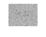
- FIG. 2 is a diagram showing a binarized image of a SEM observation photograph of a cemented carbide fired at a heating rate of 2 (° C./min).
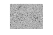
- FIG. 3 is a diagram showing a binarized image of a SEM observation photograph of a cemented carbide sintered at a heating rate of 6 (° C./min).
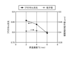
- FIG. 4 is a diagram showing the relationship between the rate of temperature increase during firing treatment, the fractal dimension of the dispersed state of the binder phase, and the particle size of the hard phase.
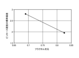
- FIG. 5 is a diagram showing the relationship between the fractal dimension of the dispersed state of the binder phase and the standard deviation of Vickers hardness at multiple points.
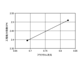
- FIG. 6 is a diagram showing the relationship between the fractal dimension of the dispersed state of the binder phase and the process capability index CPK of the deviation of the hole position.
- FIG. 1 is a diagram schematically showing the configuration of a PWB drill 1 according to an embodiment.
- the PWB drill 1 has a blade portion 2, a shank portion 3, and a connecting portion 4.
- the blade portion 2 has an elongated columnar shape, and the tip portion of the columnar shape is sharpened.
- one or a plurality of spiral chip discharge grooves 2a extending from the distal end side to the proximal end side are formed on the side surface of the blade portion 2 .
- the blade portion 2 includes a hard phase containing W (tungsten) and C (carbon) and an iron group metal (at least one of Co (cobalt), Ni (nickel) and Fe (iron)). cemented carbide with a binder phase containing
- the shank part 3 has, for example, a cylindrical shape with an outer diameter larger than that of the blade part 2 .
- the shank portion 3 is made of, for example, stainless steel. Thereby, the manufacturing cost of the PWB drill 1 can be reduced as compared with the case where the entire PWB drill 1 is made of cemented carbide.
- the connecting portion 4 connects the blade portion 2 and the shank portion 3 having different outer diameters.
- the connecting portion 4 has a first tapered portion 4a, a second tapered portion 4b, and a cylindrical portion 4c.
- the first tapered portion 4a is integrally formed with the shank portion 3, and the outer diameter gradually decreases toward the tip portion. That is, the first tapered portion 4a is made of the same material as the shank portion 3 (stainless steel, etc.).
- the second tapered portion 4b is formed integrally with the blade portion 2, and its outer diameter gradually increases with increasing distance from the tip portion. That is, the second taper portion 4b is made of the same material as the blade portion 2 (cemented carbide).
- a portion of the columnar portion 4c is integrally formed with the first tapered portion 4a, and the remainder is integrally formed with the second tapered portion 4b.
- Cemented carbide and stainless steel are joined at a joint surface 4d located in the cylindrical portion 4c, and the blade portion 2 and the shank portion 3 are connected.
- the PWB drill 1 according to the embodiment is not limited to the example of FIG. 1, and may have any configuration as long as at least the cutting portion 2 is made of cemented carbide.
- the fractal dimension of the state of dispersion of the binder phase in the hard phase is 0.7 or more.
- the value of the fractal dimension of the state of dispersion of the binder phase indicates the state of dispersion of the binder phase in the sintered body.
- the uniformity of the binder phase dispersion correlates with the variation in the Vickers hardness of the sintered body. Specifically, the higher the uniformity of the dispersion of the binder phase, the smaller the variation in the Vickers hardness of the sintered body from a microscopic point of view, and the smaller the standard deviation. Therefore, having a high value of fractal dimension makes it possible to homogenize the dispersion state of the binder phase and reduce the formation of uneven portions in the hard phase in the cemented carbide.
- uneven wear during cutting can be reduced because variations in hardness in the cemented carbide can be reduced.
- the fractal dimension of the dispersed state of the binder phase in the hard phase may be 0.8 or more. This can further reduce the formation of uneven portions in the hard phase in the cemented carbide.
- the standard deviation of the Vickers hardness at a plurality of points measured in the 400 ( ⁇ m 2 ) region in the cemented carbide forming the blade portion 2 may be 2.5 or less. In this way, uneven wear during cutting can be further reduced by reducing variation in hardness in minute regions such as the cutting edge.
- the process capability index CPK of 2.45 or more may be the deviation of the hole position when a hole is made in a member such as a printed circuit board by the tip of the blade portion 2 . In this way, by improving the accuracy of the hole position, uneven wear during cutting can be further reduced, so that the life of the PWB drill 1 can be extended.
- cemented carbide using cobalt as a binder phase is shown, but the present disclosure is not limited to the following examples.
- tungsten carbide (WC) powder 75 to 98.9 (wt%) having an average particle size of 0.1 to 1 ( ⁇ m), cobalt powder 1 to 20 (wt%), and periodic table 4A group, 5A 0.1 to 5 (wt%) of carbide powder of at least one element selected from group and 6A group, and various powders so that it becomes 100 (wt%) in a state containing other unavoidable impurities Formulated.
- metallic tungsten (W) powder or carbon black (C) may be blended as desired.
- water or an organic solvent solvent and, if desired, an organic binder are added to the prepared mixed powder and mixed, pulverized and mixed by a known method such as a ball mill or a vibration mill, and then subjected to a spray dryer. dried and granulated.
- this granular mixed powder was formed into a predetermined cutting tool shape as shown in FIG. .
- this molded body is fired in a firing furnace in a vacuum or in a non-oxidizing atmosphere such as Ar or N2 at a firing temperature of 1350 to 1450 (° C.) for 0.5 to 5 hours, and then fired.
- HIP sintering was performed at a temperature 5 to 50 (° C.) lower than the temperature, a pressure of 5 to 20 (MPa), and a pressure of 0.5 to 3 (hours) to prepare cemented carbides for cutting tools of Examples and Comparative Examples. .
- the crystalline state in the cemented carbide is controlled by adjusting the maximum firing temperature itself to the same temperature, while varying the heating rate just before the firing temperature reaches the maximum temperature.
- the firing temperature was allowed to reach the maximum temperature without changing the heating rate.
- the temperature of the firing furnace was first raised at a heating rate of V1, and immediately before reaching the maximum temperature, the heating rate was changed to V2.
- the temperature increase rate V2 was set to be smaller than the temperature increase rate V1.
- the sintering temperature reached the maximum temperature at a constant heating rate V0. More specifically, the temperature increase rate V0 and the temperature increase rate V1 were set to 8 (°C/min).
- three cemented carbides having a heating rate V2 of 2 (° C./min), 4 (° C./min), and 6 (° C./min) were prepared.
- changing the heating rate immediately before means changing the heating temperature at the timing when the firing temperature reaches about 80 to 99% of the maximum temperature value.
- the maximum temperature is 1400 (° C.)
- the heating rate is changed at the timing when the firing temperature reaches 1358 (° C.)
- 97% is changed.
- the rate of temperature increase immediately before is changed.
- the crystalline state in the cemented carbide is controlled by changing the heating rate immediately before the sintering temperature reaches the maximum temperature, but the control of the crystalline state is limited to such a method. not. If the fractal dimension of the state of dispersion of the binder phase in the hard phase can be increased, for example, the particle size distribution in the mixed powder is changed, or a solvent such as water or an organic solvent is added to the mixed powder and mixed. In some cases, the crystalline state in the cemented carbide may be controlled by further adding an organic substance different from the organic substance contained in the solvent.
- the manufactured cemented carbide may be used as a substrate, and a coating film may be formed on the surface of the substrate.
- a coating film include titanium carbide (TiC), titanium nitride (TiN), titanium carbonitride (TiCN), titanium-aluminum composite nitride (TiAlN), and aluminum oxide (Al 2 O 3 ).
- a method for forming such a coating film well-known film forming methods such as chemical vapor deposition (thermal CVD, plasma CVD, organic CVD, catalytic CVD, etc.) and physical vapor deposition (ion plating, sputtering, etc.) can be used. can be used.
- chemical vapor deposition thermal CVD, plasma CVD, organic CVD, catalytic CVD, etc.
- physical vapor deposition ion plating, sputtering, etc.
- the obtained cemented carbide for cutting tools is polished at predetermined locations, and the polished surface is observed with a field emission scanning electron microscope (FE-SEM) manufactured by JEOL at a magnification of 2000 and an accelerating voltage. : 10 (kV), Brightness: 581, Contrast: 4630, 5 fields of view per sample were photographed.
- FE-SEM field emission scanning electron microscope
- the photographs taken were analyzed using the computer software "ImageJ” (developed by Wayne Rasband National Institutes of Health). Specifically, first, the photograph was loaded into ImageJ, and using "Trainable Weka Segmentation” in ImageJ, the hard phase and the bonding phase were binarized.
- one photograph was selected from the photographs taken, and at least four ranges were extracted from Co (black part) and the hard phase (other than that), and the binarization conditions were determined. This condition was applied to the remaining four photographs, and binarization processing was performed on each of the five photographs.
- this binarized image was subjected to fractal analysis using the box counting method using "Fractal Box Count" in ImageJ.
- the Box sizes to be divided were 5, 6, 7, 8, 9, and 10.
- the fractal dimension of the cemented carbide to be evaluated was specified by calculating the fractal value for each of the five photographs described above and averaging the obtained five fractal values.
- the average value of the circle-equivalent diameter (hereinafter also referred to as the particle diameter) of the crystal grain diameter of the hard phase in the photographed photograph was calculated.
- the hardness distribution in a minute region was measured for the obtained cemented carbide for cutting tools. Specifically, using a micro Vickers hardness tester, the hardness is measured at a total of 100 locations at intervals of about 2 ( ⁇ m) in length and width in a measurement area of 400 ( ⁇ m 2 ) (for example, 20 ( ⁇ m) square). , 5 fields of view per sample were measured in the same test.
- the hardness distribution of the obtained multiple Vickers hardnesses was histogrammed and approximated by a normal distribution to obtain the standard deviation of the Vickers hardness.
- the deviation of the hole position when the member was bored was evaluated by the process capability index CPK.
- six PWB drills 1 with a drill diameter of 150 ( ⁇ m ⁇ ) and a substrate for a printed wiring board are prepared.
- 10000 holes are drilled per drill in the prepared substrate for printed wiring board.
- CPK (standard value - average value) / (3 x standard deviation) (1)
- the process capability index CPK is calculated with a standard value of 75 ( ⁇ m).
- the process capability index CPK for six drills was measured and then averaged to obtain the overall process capability index CPK.
- FIG. 2 is a diagram showing a binarized image of an SEM observation photograph of a cemented carbide fired at a heating rate of 2 (° C./min)
- FIG. 3 is a binarized image at a heating rate of 6 (° C./min). It is a figure which shows the image which digitized the SEM observation photograph of the cemented carbide which carried out the baking process.
- FIG. 4 is a diagram showing the relationship between the heating rate during the firing treatment, the fractal dimension of the dispersed state of the binder phase, and the particle size of the hard phase.
- the fractal dimension indicating the dispersion state of the binder phase is improved (that is, the binder phase is good).
- the smaller the heating rate V2 the higher the fractal dimension.
- the temperature increase rate V2 is lower than the temperature increase rate V1
- the temperature increase rate V1 while avoiding an excessive increase in the time required for the entire firing treatment, the temperature immediately before reaching the maximum temperature that greatly affects the dispersed state of the binder phase. Long baking time can be ensured. Therefore, it is considered that the homogenization of the dispersed state of the binder phase is promoted, and the fractal dimension is likely to be efficiently increased.
- the lower the rate of temperature rise V2 the longer the firing time just before reaching the maximum temperature. Therefore, it is considered that the uniformity of the dispersed state of the binder phase is further promoted, and the fractal dimension is likely to be increased.
- the temperature increase rate V2 may be constant or may be changed.
- the temperature increase rate V2 may be configured by a first stage indicated by a constant temperature increase rate V21 and a second stage indicated by a constant temperature increase rate V22 (but a value different from V21). good.
- the temperature increase rate V22 may be smaller than the temperature increase rate V21.
- the temperature increase rate V2 is composed of a plurality of stages as described above, and when the temperature increase rate in each stage is constant, compared with the case where the temperature increase rate V2 changes continuously As a result, it becomes easy to control the temperature of the firing furnace. Therefore, for example, variations in the fractal dimension due to the position of the cemented carbide in the firing furnace and variations in the firing process depending on the operator are easily avoided. That is, the fractal dimension of the cemented carbide is stabilized and the reproducibility is improved.
- the particle size of the hard phase hardly changes even when the heating rate immediately before reaching the maximum temperature is changed.
- the dispersed state of the binder phase can be controlled without changing the hardness characteristics of the cemented carbide.
- FIG. 5 is a diagram showing the relationship between the fractal dimension of the dispersed state of the binder phase and the standard deviation of Vickers hardness at multiple points. As shown in FIG. 5, by setting the fractal dimension to 0.7 or more, the standard deviation of the Vickers hardness can be reduced to a favorable value.
- the hardness distribution in the minute region can be made uniform, so uneven wear during cutting can be reduced.
- the fractal dimension 0.8 or more
- the standard deviation of the Vickers hardness can be reduced to an even better value.
- the hardness distribution in the minute regions can be made more uniform, so uneven wear during cutting can be further reduced.
- the upper limit of the fractal dimension may be 2 or less, preferably 1 or less, from the viewpoint of manufacturing efficiency.
- the hardness distribution in the minute regions can be made uniform, so uneven wear during cutting can be reduced.
- FIG. 6 is a diagram showing the relationship between the fractal dimension of the dispersed state of the binder phase and the process capability index CPK of the deviation of the hole position. As shown in FIG. 6, by setting the fractal dimension to 0.7 or more, the process capability index CPK can be improved to a favorable value.
- the accuracy of the hole position can be improved. Therefore, according to the embodiment, since uneven wear during cutting can be reduced, the life of the PWB drill 1 can be extended.
- the process capability index CPK can be improved to a better value. Therefore, according to the embodiment, the life of the PWB drill 1 can be further extended.
Landscapes
- Engineering & Computer Science (AREA)
- Mechanical Engineering (AREA)
- Chemical & Material Sciences (AREA)
- Materials Engineering (AREA)
- Metallurgy (AREA)
- Organic Chemistry (AREA)
- Life Sciences & Earth Sciences (AREA)
- Forests & Forestry (AREA)
- Composite Materials (AREA)
- Manufacturing & Machinery (AREA)
- Drilling Tools (AREA)
- Cutting Tools, Boring Holders, And Turrets (AREA)
Abstract
超硬合金は、WおよびCを含有する硬質相と、鉄族金属を含有する結合相と、を有する。また、結合相の分散状態のフラクタル次元が0.7以上である。
Description
開示の実施形態は、超硬合金および切削工具に関する。
近年、プリント基板穴あけ用の極小径ドリル(以下、PWBドリルとも呼称する。)に代表される電子機器類への微細加工用工具の必要性が高まっている(例えば、特許文献1参照)。
また、被加工部材であるプリント基板では、近年軽薄短小化が進み、さらに要求される電気的信頼性の高度化にともなって、高耐熱化、高放熱化および高剛性化が求められている。そこで、これらの要求を満足するために、プリント基板の構成材料であるガラス繊維強化樹脂への無機フィラーの高充填化や、ガラス繊維の高密度化が図られている。
本開示の超硬合金は、WおよびCを含有する硬質相と、鉄族金属を含有する結合相と、を有する。また、前記結合相の分散状態のフラクタル次元が0.7以上である。
以下、添付図面を参照して、本願の開示する超硬合金および切削工具の実施形態について説明する。なお、以下に示す実施形態によりこの発明が限定されるものではない。
近年、プリント基板穴あけ用の極小径ドリル(以下、PWBドリルとも呼称する。)に代表される電子機器類への微細加工用工具の必要性が高まっている。
また、被加工部材であるプリント基板では、近年軽薄短小化が進み、さらに要求される電気的信頼性の高度化にともなって、高耐熱化、高放熱化および高剛性化が求められている。そこで、これらの要求を満足するために、プリント基板の構成材料であるガラス繊維強化樹脂への無機フィラーの高充填化や、ガラス繊維の高密度化が図られている。
一方で、上記の従来技術では、プリント基板内の無機フィラー量やガラス繊維量が多くなるにしたがい、プリント基板の切削時にPWBドリルの刃先が偏摩耗しやすくなる場合があった。これにより、穴位置精度の悪化、内壁面の粗度の悪化およびPWBドリルの折損などの不具合が生じる恐れがあった。
そこで、上述の問題点を克服し、PWBドリルにおいて切削時の偏摩耗を低減できる技術の実現が期待されている。
<PWBドリル>
最初に、実施形態に係るPWBドリル1の構成について、図1を参照しながら説明する。図1は、実施形態に係るPWBドリル1の構成を概略的に示した図である。
最初に、実施形態に係るPWBドリル1の構成について、図1を参照しながら説明する。図1は、実施形態に係るPWBドリル1の構成を概略的に示した図である。
図1に示すように、実施形態に係るPWBドリル1は、刃部2と、シャンク部3と、連結部4とを有する。刃部2は、長尺の円柱形状を有し、かかる円柱形状の先端部に刃付け加工が施される。また、刃部2の側面には、先端側から基端側に向かうらせん状の切り屑排出溝2aが1または複数形成される。
実施形態に係る刃部2は、W(タングステン)およびC(炭素)を含有する硬質相と、鉄族金属(Co(コバルト)、Ni(ニッケル)およびFe(鉄)のうち少なくとも1種)を含有する結合相とを有する超硬合金で構成される。
シャンク部3は、たとえば、刃部2よりも外径が大きい円柱形状を有する。シャンク部3は、たとえば、ステンレス鋼などで構成される。これにより、PWBドリル1の全体を超硬合金で構成する場合と比較して、PWBドリル1の製造コストを低減することができる。
連結部4は、外径の異なる刃部2とシャンク部3との間を連結する。連結部4は、第1テーパ部4aと、第2テーパ部4bと、円柱部4cとを有する。
第1テーパ部4aは、シャンク部3と一体で構成され、先端部に進むにしたがい外径が徐々に小さくなっている。すなわち、第1テーパ部4aは、シャンク部3と同じ材料(ステンレス鋼など)で構成される。
第2テーパ部4bは、刃部2と一体で構成され、先端部から離れるにしたがい外径が徐々に大きくなっている。すなわち、第2テーパ部4bは、刃部2と同じ材料(超硬合金)で構成される。
円柱部4cは、一部が第1テーパ部4aと一体で構成され、残りが第2テーパ部4bと一体で構成される。そして、円柱部4cに位置する接合面4dにおいて超硬合金とステンレス鋼とが接合され、刃部2とシャンク部3との間が連結される。
なお、実施形態に係るPWBドリル1は、図1の例に限られず、少なくとも刃部2が超硬合金で構成されてさえいれば、どのような構成であってもよい。
ここで、実施形態では、刃部2を構成する超硬合金において、硬質相中における結合相の分散状態のフラクタル次元が0.7以上である。結合相の分散状態のフラクタル次元の値は、焼結体中における結合相の分散状態を示しているので、結合相の分散のフラクタル次元の値が高いほど、結合相の分散が均一になることを意味する。
結合相の分散の均一性は、焼結体のビッカース硬度のばらつきに対して相関性がある。具体的には、結合相の分散の均一性が高くなるほど、焼結体のミクロな観点でのビッカース硬度のバラツキが小さく、標準偏差が小さくなる。従って、高いフラクタル次元の値を有することで、結合相の分散状態が均一化し、超硬合金中の硬質相に不均一な部分が形成されることを低減できる。
したがって、実施形態によれば、超硬合金中での硬度のばらつきを低減できることから、切削時の偏摩耗を低減できる。
また、実施形態では、刃部2を構成する超硬合金において、硬質相中における結合相の分散状態のフラクタル次元が0.8以上であってもよい。これにより、超硬合金中の硬質相に不均一な部分が形成されることをさらに低減できる。
したがって、実施形態によれば、超硬合金中での硬度のばらつきをさらに低減できることから、切削時の偏摩耗をさらに低減できる。
また、実施形態では、刃部2を構成する超硬合金において、400(μm2)領域において測定された複数点のビッカース硬度の標準偏差が、2.5以下であってもよい。このように、刃先などの微小領域における硬度のばらつきが低減されることで、切削時の偏摩耗をさらに低減できる。
また、実施形態では、刃部2の先端部によってプリント基板などの部材に穴を空けた際の穴位置のずれ具合が、工程能力指数CPKで2.45以上であってもよい。このように、穴位置の精度が向上することで、切削時の偏摩耗をさらに低減できることから、PWBドリル1の長寿命化を実現することができる。
以下、本開示の実施例を具体的に説明する。なお、以下に説明する実施例では、結合相としてコバルトを用いた超硬合金について示すが、本開示は以下の実施例に限定されるものではない。
まず、平均粒径0.1~1(μm)の炭化タングステン(WC)粉末75~98.9(wt%)と、コバルト粉末1~20(wt%)と、周期律表の4A族、5A族、6A族から選択される少なくとも1種の元素の炭化物粉末0.1~5(wt%)と、その他の不可避不純物とを含んだ状態で100(wt%)になるように各種の粉末を調合した。なお、本開示では、さらに所望により、金属タングステン(W)粉末、あるいはカーボンブラック(C)を調合してもよい。
次に、調合された混合粉末に水または有機溶剤の溶媒と、所望により有機バインダとを添加して混合し、ボールミル、振動ミルなどの既知の方法にて粉砕、混合し、その後、スプレードライヤーにて乾燥させて顆粒状とした。
次に、この顆粒状の混合粉末を、プレス成形、鋳込成形、押出成形、冷間静水圧プレス成形などの公知の成形方法によって、図1に示したような所定の切削工具形状に成形した。
次に、この成形体を焼成炉中にて、真空、またはAr、N2などの非酸化雰囲気にて焼成温度1350~1450(℃)、0.5~5(時間)焼成した後、かかる焼成温度より5~50(℃)低い温度、圧力5~20(MPa)、0.5~3(時間)でHIP焼結を行い、実施例及び比較例の切削工具用の超硬合金を作成した。
本開示では、焼成温度の最高温度自体は同じ温度にすべて揃える一方で、焼成温度が最高温度に達する直前の昇温速度をさまざまに変化させることで、超硬合金内の結晶状態を制御した。また、比較例においては、昇温速度を変化させずに焼成温度を最高温度に到達させた。
具体的には、実施例の超硬合金においては、まず昇温速度V1で焼成炉の温度を上昇させ、最高温度に達する直前に昇温速度をV2に変化させた。このとき、昇温速度V2が昇温速度V1よりも小さくなるように設定した。また、実施例の超硬合金においては、一定の昇温速度V0で焼成温度を最高温度に到達させた。より具体的には、昇温速度V0及び昇温速度V1を8(℃/min)に設定した。また、実施例として、昇温速度V2を2(℃/min)、4(℃/min)、6(℃/min)とする3つの超硬合金を準備した。
ここで、直前の昇温速度を変化させるとは、焼成温度が最高温度の値に対して80~99%程度となったタイミングで昇温温度を変化させることを意味する。例えば、最高温度が1400(℃)である場合に、焼成温度が1358(℃)になったタイミングで昇温速度を変化させた際には、最高温度の値に対して97%(=1358℃/1400℃)となったタイミングで昇温温度を変化させることになる。この場合には、直前の昇温速度を変化させると言える。
なお、本開示では、焼成温度が最高温度に達する直前の昇温速度を変化させることによって超硬合金内の結晶状態を制御しているが、結晶状態の制御は、このような手法には限定されない。硬質相中における結合相の分散状態のフラクタル次元を高めることができるのであれば、例えば、混合粉末における粒径分布を変更する、あるいは、混合粉末に水または有機溶剤の溶媒を添加して混合する際に、溶媒に含まれる有機物とは異なる有機物をさらに添加することによって、超硬合金内の結晶状態を制御してもよい。
本開示では、所望により、作成された超硬合金を基体として、基体表面に被覆膜を形成してもよい。かかる被覆膜としては、炭化チタン(TiC)、窒化チタン(TiN)および炭窒化チタン(TiCN)、チタン・アルミ複合窒化物(TiAlN)、酸化アルミニウム(Al2O3)などが挙げられる。
また、かかる被覆膜の成膜方法としては、化学蒸着法(熱CVD、プラズマCVD、有機CVD、触媒CVD等)、物理蒸着法(イオンプレーティング、スパッタリング等)などの周知の成膜方法を使用することができる。
次に、得られた切削工具用の超硬合金について、所定の箇所を研磨し、かかる研磨面をJEOL製の電解放出型走査電子顕微鏡(FE-SEM)にて、倍率:2000倍、加速電圧:10(kV)、Brightness:581、Contrast:4630、の条件で1サンプルあたり5視野撮影した。
次に、撮影した写真を、コンピュータソフトウェア「ImageJ」(開発:Wayne Rasband National Institutes of Health)を使用して解析した。具体的には、まず、ImageJに写真を取り込み、ImageJ中の「Trainable Weka Segmentation」を用いて、硬質相と結合相の二値化処理を行った。
かかる二値化処理では、撮影した写真から1枚選択し、Co(黒色部)と硬質相(それ以外)から少なくとも四範囲ずつ抽出し、二値化の条件を決定した。この条件を、残りの4枚の写真へ適用し、5枚の写真のそれぞれにおいて二値化処理を行った。
次に、この二値化した画像を、ImageJ中の「Fractal Box Count…」を用いて、ボックスカウンティング法でフラクタル解析を行った。この際、分割するBoxサイズは5、6、7、8、9、10とした。上記した5枚の写真のそれぞれにおいてフラクタル値を算出し、得られた5つのフラクタル値を平均することによって、評価対象の超硬合金のフラクタル次元を特定した。
また、ImageJを用いて、撮影した写真における硬質相の結晶粒径の円相当径(以下、粒子径とも呼称する。)の平均値を算出した。
また、得られた切削工具用の超硬合金について、微小領域における硬度分布を測定した。具体的には、マイクロビッカース硬度計を用いて、400(μm2)(たとえば、20(μm)四方)の測定領域において縦横約2(μm)の間隔で計100箇所の硬度を測定し、さらに、同様の試験を1サンプルあたり5視野測定した。
そして、得られた複数のビッカース硬度の硬度分布をヒストグラム化して正規分布で近似し、ビッカース硬度の標準偏差を求めた。
また、得られた切削工具用の超硬合金について、部材に穴を空けた際の穴位置のずれ具合を、工程能力指数CPKによって評価した。具体的には、ドリル径150(μmΦ)のPWBドリル1を6本とプリント配線板用の基板とを準備する。次に、準備したプリント配線板用基板へ、準備したPWBドリル1を使用して、ドリル一本当たり10000穴を開ける。
次に、開けた穴と中心の目標位置の間の距離を測定し、穴位置精度データとする。そして、測定した穴位置精度のデータの平均値と標準偏差を求める。最後に、求めた平均値と標準偏差の値を用いて、下記の式(1)より、工程能力指数CPKを求める。
CPK=(規格値-平均値)/(3×標準偏差) ・・・(1)
CPK=(規格値-平均値)/(3×標準偏差) ・・・(1)
なお、本開示では、規格値を75(μm)として工程能力指数CPKを算出している。また、本開示では、ドリル6本分の工程能力指数CPKを測定後、平均して全体の工程能力指数CPKとした。
図2は、昇温速度2(℃/min)で焼成処理した超硬合金のSEM観察写真を二値化した画像を示す図であり、図3は、昇温速度6(℃/min)で焼成処理した超硬合金のSEM観察写真を二値化した画像を示す図である。
図2および図3に示すように、最高温度に達するまでの昇温速度を低くすることで、結合相(黒色部)の分散状態が良好になっていることが分かる。
図4は、焼成処理時の昇温速度と、結合相の分散状態のフラクタル次元および硬質相の粒子径との関係を示す図である。
図4に示すように、最高温度に達するまでの昇温速度V2を初期の昇温速度V1よりも低くすることで、結合相の分散状態を示すフラクタル次元が向上している(すなわち、結合相の分散状態が良好になっている)ことが分かる。特に、昇温速度V2が小さいほどにフラクタル次元が高くなることが分かる。
昇温速度V2が昇温速度V1よりも小さい場合には、焼成処理の全体に要する時間が過度に増加することを避けつつ、結合相の分散状態への影響の大きい最高温度に達する直前での焼成時間を長く確保できる。そのため、結合相の分散状態の均一化が促され、フラクタル次元が効率よく高められ易いと考えられる。特に、昇温速度V2が小さくなるほどに最高温度に達する直前での焼成時間をより長く確保できる。そのため、結合相の分散状態の均一化がより促され、フラクタル次元がより高められ易いと考えられる。
昇温速度V2は、一定であってもよく、また、変化させてもよい。例えば、昇温速度V2が、一定の昇温速度V21で示される第1段階と、一定の昇温速度V22(ただし、V21とは異なる値)で示される第2段階と、によって構成されてもよい。このとき、昇温速度V22が昇温速度V21より小さくてもよい。このように昇温速度V2が徐々に小さくなる場合には、結合相の分散状態への影響の大きい最高温度に達する直前での焼成時間をより長く確保できる。そのため、結合相の分散状態の均一化がより促され、フラクタル次元がより高められ易いと考えられる。
また、昇温速度V2が上記したような複数の段階で構成される場合であって、各段階の昇温速度が一定である場合には、昇温速度V2が連続的に変化する場合と比較して、焼成炉の温度制御が容易となる。そのため例えば、焼成炉内での超硬合金の位置に起因するフラクタル次元のばらつき、及び、作業者による焼成処理のばらつきなどが避けられやすい。すなわち、超硬合金のフラクタル次元が安定し、再現性が良好となる。
さらに、本開示では、最高温度自体は揃えていることから、最高温度に達する直前の昇温速度を変更した場合でも、硬質相の粒子径はほとんど変化していないことが分かる。これにより、超硬合金の硬度特性などを変化させることなく、結合相の分散状態を制御することができる。
図5は、結合相の分散状態のフラクタル次元と複数点のビッカース硬度の標準偏差との関係を示す図である。図5に示すように、フラクタル次元を0.7以上とすることで、ビッカース硬度の標準偏差を良好な値に低減させることができる。
すなわち、実施形態では、フラクタル次元を0.7以上とすることで、微小領域における硬度分布を均一化できることから、切削時の偏摩耗を低減できる。
また、実施形態では、フラクタル次元を0.8以上とすることで、ビッカース硬度の標準偏差をさらに良好な値に低減させることができる。これにより、微小領域における硬度分布をさらに均一化できることから、切削時の偏摩耗をさらに低減できる。
なお、本開示において、フラクタル次元の上限値は、製造効率などの観点から、2以下であればよく、1以下であることが好ましい。
また、実施形態では、複数点のビッカース硬度の標準偏差を2.5以下とすることで、微小領域における硬度分布を均一化できることから、切削時の偏摩耗を低減できる。
図6は、結合相の分散状態のフラクタル次元と穴位置のずれ具合の工程能力指数CPKとの関係を示す図である。図6に示すように、フラクタル次元を0.7以上とすることで、工程能力指数CPKを良好な値に向上させることができる。
すなわち、実施形態では、結合相の分散状態のフラクタル次元を0.7以上とすることで、穴位置の精度を向上させることができる。したがって、実施形態によれば、切削時の偏摩耗を低減できることから、PWBドリル1の長寿命化を実現することができる。
また、実施形態では、結合相の分散状態のフラクタル次元を0.8以上とすることで、工程能力指数CPKをさらに良好な値に向上させることができる。したがって、実施形態によれば、PWBドリル1のさらなる長寿命化を実現することができる。
また、実施形態では、工程能力指数CPKを2.45以上とすることで、切削時の偏摩耗を低減できることから、PWBドリル1の長寿命化を実現することができる。
以上、本発明の実施形態について説明したが、本発明は上記実施形態に限定されるものではなく、その趣旨を逸脱しない限りにおいて種々の変更が可能である。たとえば、上記の実施形態では、上述の超硬合金をPWBドリルに用いる例について示したが、本開示はかかる例に限られず、上述の超硬合金はチップなどの各種の切削工具に用いられてもよい。
さらなる効果や他の態様は、当業者によって容易に導き出すことができる。このため、本発明のより広範な態様は、以上のように表しかつ記述した特定の詳細および代表的な実施形態に限定されるものではない。したがって、添付の請求の範囲およびその均等物によって定義される総括的な発明の概念の精神または範囲から逸脱することなく、様々な変更が可能である。
1 PWBドリル
2 刃部
3 シャンク部
4 連結部
2 刃部
3 シャンク部
4 連結部
Claims (5)
- WおよびCを含有する硬質相と、
鉄族金属を含有する結合相と、
を有し、
前記結合相の分散状態のフラクタル次元が0.7以上である
超硬合金。 - 前記結合相の分散状態のフラクタル次元が0.8以上である
請求項1に記載の超硬合金。 - 400(μm2)領域において測定された複数点のビッカース硬度の標準偏差が2.5以下である
請求項1または2に記載の超硬合金。 - 円柱長尺形状の請求項1~3のいずれか一つに記載の超硬合金の一方の端部がシャンク部に接合されているとともに、他方の端部に刃付け加工が施されている
切削工具。 - 前記他方の端部によって部材に穴を空けた際の穴位置のずれ具合が、工程能力指数CPKで2.45以上である
請求項4に記載の切削工具。
Priority Applications (1)
| Application Number | Priority Date | Filing Date | Title |
|---|---|---|---|
| JP2023569354A JP7824323B2 (ja) | 2021-12-22 | 2022-12-14 | 超硬合金および切削工具 |
Applications Claiming Priority (2)
| Application Number | Priority Date | Filing Date | Title |
|---|---|---|---|
| JP2021208711 | 2021-12-22 | ||
| JP2021-208711 | 2021-12-22 |
Publications (1)
| Publication Number | Publication Date |
|---|---|
| WO2023120342A1 true WO2023120342A1 (ja) | 2023-06-29 |
Family
ID=86902547
Family Applications (1)
| Application Number | Title | Priority Date | Filing Date |
|---|---|---|---|
| PCT/JP2022/046114 Ceased WO2023120342A1 (ja) | 2021-12-22 | 2022-12-14 | 超硬合金および切削工具 |
Country Status (3)
| Country | Link |
|---|---|
| JP (1) | JP7824323B2 (ja) |
| TW (1) | TWI842287B (ja) |
| WO (1) | WO2023120342A1 (ja) |
Citations (5)
| Publication number | Priority date | Publication date | Assignee | Title |
|---|---|---|---|---|
| JP2012148384A (ja) * | 2011-01-21 | 2012-08-09 | Carbide Internatl Co Ltd | ドリルビット構造 |
| JP2016030314A (ja) * | 2014-07-29 | 2016-03-07 | 京セラ株式会社 | ドリル用ブランク、ドリル用ブランクの製造方法、およびドリル |
| JP2016132805A (ja) * | 2015-01-20 | 2016-07-25 | 京セラ株式会社 | 切削工具用ブランク、切削工具用ブランクの製造方法、および切削工具並びに切削工具の製造方法 |
| CN113042730A (zh) * | 2021-03-16 | 2021-06-29 | 厦门钨业股份有限公司 | 一种wc基硬质合金粉体及其定量表征方法和硬质合金 |
| CN113322389A (zh) * | 2021-06-01 | 2021-08-31 | 株洲硬质合金集团有限公司 | 一种耐磨损耐腐蚀超细硬质合金的烧结方法 |
-
2022
- 2022-12-14 JP JP2023569354A patent/JP7824323B2/ja active Active
- 2022-12-14 WO PCT/JP2022/046114 patent/WO2023120342A1/ja not_active Ceased
- 2022-12-20 TW TW111149024A patent/TWI842287B/zh active
Patent Citations (5)
| Publication number | Priority date | Publication date | Assignee | Title |
|---|---|---|---|---|
| JP2012148384A (ja) * | 2011-01-21 | 2012-08-09 | Carbide Internatl Co Ltd | ドリルビット構造 |
| JP2016030314A (ja) * | 2014-07-29 | 2016-03-07 | 京セラ株式会社 | ドリル用ブランク、ドリル用ブランクの製造方法、およびドリル |
| JP2016132805A (ja) * | 2015-01-20 | 2016-07-25 | 京セラ株式会社 | 切削工具用ブランク、切削工具用ブランクの製造方法、および切削工具並びに切削工具の製造方法 |
| CN113042730A (zh) * | 2021-03-16 | 2021-06-29 | 厦门钨业股份有限公司 | 一种wc基硬质合金粉体及其定量表征方法和硬质合金 |
| CN113322389A (zh) * | 2021-06-01 | 2021-08-31 | 株洲硬质合金集团有限公司 | 一种耐磨损耐腐蚀超细硬质合金的烧结方法 |
Also Published As
| Publication number | Publication date |
|---|---|
| JP7824323B2 (ja) | 2026-03-04 |
| TW202334450A (zh) | 2023-09-01 |
| JPWO2023120342A1 (ja) | 2023-06-29 |
| TWI842287B (zh) | 2024-05-11 |
Similar Documents
| Publication | Publication Date | Title |
|---|---|---|
| JP3762777B1 (ja) | 超硬合金 | |
| JP2009035810A (ja) | 超硬合金 | |
| KR20000057148A (ko) | 다이아몬드 코팅된 부재를 제조하는 방법 | |
| JP2004076049A (ja) | 超微粒超硬合金 | |
| US6027808A (en) | Cemented carbide for a drill, and for a drill forming holes in printed circuit boards which is made of the cemented carbide | |
| JP4846519B2 (ja) | 窒化物含有ターゲット材 | |
| WO2023120342A1 (ja) | 超硬合金および切削工具 | |
| JP2003080412A (ja) | 高速穴あけ加工で先端切刃面がすぐれた耐チッピング性を発揮する表面被覆超硬合金製ミニチュアドリル | |
| US10569339B2 (en) | Surface-coated cutting tool | |
| JP2005200671A (ja) | 微粒超硬合金 | |
| JP5057751B2 (ja) | 超硬合金およびその製造方法 | |
| JP2026043559A (ja) | 超硬合金、切削工具用ブランク、切削工具、および切削加工物の製造方法 | |
| JP2008179853A (ja) | ホウ化物含有ターゲット材 | |
| JP2004174616A (ja) | 高送り条件での切削加工ですぐれた耐チッピング性を発揮する表面被覆超硬合金製エンドミルの製造方法 | |
| TW202613331A (zh) | 超硬合金、切削工具用胚料、切削工具及切削加工物的製造方法 | |
| JP4761556B2 (ja) | 窒化物含有ターゲット材 | |
| JP4846557B2 (ja) | 窒化物含有ターゲット材 | |
| US11773030B2 (en) | Cubic boron nitride sintered material, tool comprising cubic boron nitride sintered material and method for manufacturing cubic boron nitride sintered material | |
| JP5892331B2 (ja) | 潤滑特性と耐摩耗性にすぐれた表面被覆ドリル | |
| JP4609631B2 (ja) | 硬質被覆層がすぐれた耐摩耗性を発揮する表面被覆超硬合金製切削工具 | |
| JP4184783B2 (ja) | 超硬合金およびその製造方法並びにプリント基板加工用ドリル | |
| JP4483467B2 (ja) | 硬質被覆層が断続重切削加工ですぐれた耐チッピング性を発揮する表面被覆サーメット製切削工具 | |
| JP3928459B2 (ja) | 難削材の高速切削で硬質被覆層がすぐれた耐摩耗性を発揮する表面被覆超硬合金製切削工具 | |
| JP4846556B2 (ja) | 窒化物含有ターゲット材 | |
| JP2003127020A (ja) | 高速切削加工で外周刃がすぐれた耐チッピング性を発揮する表面被覆超硬合金製スクエアエンドミル |
Legal Events
| Date | Code | Title | Description |
|---|---|---|---|
| 121 | Ep: the epo has been informed by wipo that ep was designated in this application |
Ref document number: 22911050 Country of ref document: EP Kind code of ref document: A1 |
|
| WWE | Wipo information: entry into national phase |
Ref document number: 2023569354 Country of ref document: JP |
|
| NENP | Non-entry into the national phase |
Ref country code: DE |
|
| 122 | Ep: pct application non-entry in european phase |
Ref document number: 22911050 Country of ref document: EP Kind code of ref document: A1 |