WO2023112748A1 - ガイドワイヤ - Google Patents
ガイドワイヤ Download PDFInfo
- Publication number
- WO2023112748A1 WO2023112748A1 PCT/JP2022/044750 JP2022044750W WO2023112748A1 WO 2023112748 A1 WO2023112748 A1 WO 2023112748A1 JP 2022044750 W JP2022044750 W JP 2022044750W WO 2023112748 A1 WO2023112748 A1 WO 2023112748A1
- Authority
- WO
- WIPO (PCT)
- Prior art keywords
- magnetized region
- magnetized
- region
- tip
- guidewire
- Prior art date
- Legal status (The legal status is an assumption and is not a legal conclusion. Google has not performed a legal analysis and makes no representation as to the accuracy of the status listed.)
- Ceased
Links
Images


Classifications
-
- A—HUMAN NECESSITIES
- A61—MEDICAL OR VETERINARY SCIENCE; HYGIENE
- A61M—DEVICES FOR INTRODUCING MEDIA INTO, OR ONTO, THE BODY; DEVICES FOR TRANSDUCING BODY MEDIA OR FOR TAKING MEDIA FROM THE BODY; DEVICES FOR PRODUCING OR ENDING SLEEP OR STUPOR
- A61M25/00—Catheters; Hollow probes
- A61M25/01—Introducing, guiding, advancing, emplacing or holding catheters
- A61M25/09—Guide wires
-
- A—HUMAN NECESSITIES
- A61—MEDICAL OR VETERINARY SCIENCE; HYGIENE
- A61M—DEVICES FOR INTRODUCING MEDIA INTO, OR ONTO, THE BODY; DEVICES FOR TRANSDUCING BODY MEDIA OR FOR TAKING MEDIA FROM THE BODY; DEVICES FOR PRODUCING OR ENDING SLEEP OR STUPOR
- A61M25/00—Catheters; Hollow probes
- A61M25/01—Introducing, guiding, advancing, emplacing or holding catheters
- A61M25/0105—Steering means as part of the catheter or advancing means; Markers for positioning
- A61M25/0127—Magnetic means; Magnetic markers
-
- A—HUMAN NECESSITIES
- A61—MEDICAL OR VETERINARY SCIENCE; HYGIENE
- A61B—DIAGNOSIS; SURGERY; IDENTIFICATION
- A61B5/00—Measuring for diagnostic purposes; Identification of persons
- A61B5/06—Devices, other than using radiation, for detecting or locating foreign bodies ; Determining position of diagnostic devices within or on the body of the patient
- A61B5/061—Determining position of a probe within the body employing means separate from the probe, e.g. sensing internal probe position employing impedance electrodes on the surface of the body
- A61B5/062—Determining position of a probe within the body employing means separate from the probe, e.g. sensing internal probe position employing impedance electrodes on the surface of the body using magnetic field
-
- A—HUMAN NECESSITIES
- A61—MEDICAL OR VETERINARY SCIENCE; HYGIENE
- A61M—DEVICES FOR INTRODUCING MEDIA INTO, OR ONTO, THE BODY; DEVICES FOR TRANSDUCING BODY MEDIA OR FOR TAKING MEDIA FROM THE BODY; DEVICES FOR PRODUCING OR ENDING SLEEP OR STUPOR
- A61M25/00—Catheters; Hollow probes
- A61M25/01—Introducing, guiding, advancing, emplacing or holding catheters
- A61M25/09—Guide wires
- A61M2025/09058—Basic structures of guide wires
- A61M2025/09083—Basic structures of guide wires having a coil around a core
-
- A—HUMAN NECESSITIES
- A61—MEDICAL OR VETERINARY SCIENCE; HYGIENE
- A61M—DEVICES FOR INTRODUCING MEDIA INTO, OR ONTO, THE BODY; DEVICES FOR TRANSDUCING BODY MEDIA OR FOR TAKING MEDIA FROM THE BODY; DEVICES FOR PRODUCING OR ENDING SLEEP OR STUPOR
- A61M25/00—Catheters; Hollow probes
- A61M25/01—Introducing, guiding, advancing, emplacing or holding catheters
- A61M25/09—Guide wires
- A61M2025/09133—Guide wires having specific material compositions or coatings; Materials with specific mechanical behaviours, e.g. stiffness, strength to transmit torque
-
- A—HUMAN NECESSITIES
- A61—MEDICAL OR VETERINARY SCIENCE; HYGIENE
- A61M—DEVICES FOR INTRODUCING MEDIA INTO, OR ONTO, THE BODY; DEVICES FOR TRANSDUCING BODY MEDIA OR FOR TAKING MEDIA FROM THE BODY; DEVICES FOR PRODUCING OR ENDING SLEEP OR STUPOR
- A61M25/00—Catheters; Hollow probes
- A61M25/01—Introducing, guiding, advancing, emplacing or holding catheters
- A61M25/09—Guide wires
- A61M2025/09175—Guide wires having specific characteristics at the distal tip
Definitions
- the present invention relates to guidewires.
- Patent Literature 1 discloses a technique of detecting the magnetic field intensity of a plurality of magnetic domains provided in a medical device to identify the position and orientation of the medical device.
- Patent Document 2 discloses a technique for tracking the position of a guide wire around which a magnetic position sensor is wound based on magnetism.
- Patent Document 3 discloses a technique of guiding the tip portion by applying a magnetic repulsive force to a guide wire having a magnet head at the tip portion. .
- the present invention has been made to solve at least part of the above-mentioned problems, and aims to provide a guide wire capable of having a desired strength of magnetism at its distal end.
- the present invention has been made to solve at least part of the above problems, and can be implemented as the following forms.
- a guidewire is provided.
- This guide wire is a guide wire including a core wire, the core wire has a first magnetized region magnetized on the distal end side of the core wire, and the maximum value of the outer diameter of the first magnetized region is the first It is larger than the outer shape of the distal end in the region closer to the proximal end than the one magnetized region.
- the maximum value of the outer diameter of the first magnetized region on the distal end side of the core wire is larger than the outer diameter of the distal end portion of the region closer to the proximal end than the first magnetized region. For this reason, the volume of the first magnetized region per unit length can be increased compared to a core wire having a constant outer diameter on the tip side or a tapered core wire having an outer diameter that decreases toward the tip side.
- a large magnetism can be imparted to one magnetized region. That is, it is possible to impart a desired strength of magnetism to the distal end of the guide wire.
- the magnetic sensor placed outside the living body can easily detect the tip of the guidewire inserted into the lumen of the body, thus improving the detection accuracy of the tip of the guidewire by the magnetic sensor. be able to.
- the improved detection accuracy makes it easier for the operator to grasp the movement of the distal end portion of the guide wire, so that the procedure can be performed with high accuracy and efficiency.
- the core wire further has a second magnetized region magnetized at a position spaced apart from the first magnetized region on the proximal side of the first magnetized region.
- the maximum value of the outer diameter of the first magnetized region may be larger than the outer diameter of the tip portion in the region between the first magnetized region and the second magnetized region.
- the core wire has the second region magnetized on the proximal side of the first magnetized region, and the first magnetized region and the second magnetized region are separated. Therefore, the position of the first magnetized region and the position of the second magnetized region can be detected separately. Also, the degree of curvature of the guidewire in the range from the second magnetized region to the first magnetized region can be grasped from the position of the first magnetized region and the position of the second magnetized region that are detected separately.
- the second magnetized region includes a magnetized coil that covers the outer peripheral surface of the core wire, and the maximum value of the outer diameter of the coil as the second magnetized region is larger than the outer diameter of the base end in the region between the first magnetized region and the second magnetized region, and larger than the outer diameter of the tip end in the region closer to the base end than the second magnetized region good too.
- the maximum outer diameter of the core wire in the second magnetized region is the base end portion in the region between the first magnetized region and the second magnetized region. and larger than the outer diameter of the distal end portion of the region closer to the proximal end than the second magnetized region.
- the core wire may have a curved portion in which the core wire is curved in a region between the first magnetization region and the second magnetization region. According to this configuration, it is possible to improve the accuracy of distinguishing and detecting the first magnetized region provided on the distal side of the curved portion and the second magnetized region provided on the proximal side of the curved portion. Then, by using the position of the first magnetized region and the position of the second magnetized region that are separately detected, the three-dimensional movement of the tip of the guidewire can be accurately grasped. Specifically, when deformation such as bending occurs in the guide wire, the tip side mainly deforms rather than the bending portion.
- the three-dimensional movement of the distal end portion of the guidewire can be accurately grasped. be.
- the operator can proceed with the procedure with high accuracy and efficiency.
- the proximal end portion of the first magnetized region may be formed with an enlarged diameter portion whose outer diameter gradually increases from the proximal side to the distal side. According to this configuration, it is possible to suppress the bending of the base end portion of the first magnetized region by making it difficult to create a rigidity gap in which the bending rigidity greatly changes at the base end portion of the first magnetized region. The volume of the first magnetized region can be increased.
- a tip reduced diameter portion may be formed at the tip of the first magnetized region, the outer diameter of which gradually decreases from the proximal side to the distal side.
- a guidewire is provided.
- the guidewire is a guidewire comprising a core wire and a coil covering the core wire, the coil having a magnetized region that is magnetized, and strands forming the magnetized region of the coil is thicker than the wire forming the tip portion in the region closer to the base end than the magnetized region.
- the wire forming the magnetized region is thicker than the wire forming the tip portion in the region closer to the base end than the magnetized region. Therefore, the volume of the magnetized region per unit length can be increased, so that the magnetized region can have a large magnetism.
- the present invention can be implemented in various aspects, for example, a core wire used as a guide wire, a medical device including a guide wire, a method for manufacturing a core wire or a guide wire, a guide wire inserted into the body can be implemented in the form of a system for detecting the position of
- FIG. 1 is an explanatory diagram showing a schematic configuration of a guidewire according to a first embodiment
- FIG. 1 is a cross-sectional view of the guidewire of the first embodiment
- FIG. 4 is a flow chart of a method for manufacturing the guidewire of the first embodiment
- FIG. 4 is an explanatory view showing a manufacturing process of the guidewire of the first embodiment
- FIG. 5 is an explanatory diagram showing a schematic configuration of a guidewire according to a second embodiment
- FIG. 4 is a cross-sectional view of a guidewire of a second embodiment
- FIG. 10 is an explanatory view showing the manufacturing process of the guidewire of the second embodiment
- FIG. 11 is an explanatory diagram showing a schematic configuration of a guidewire according to a third embodiment
- FIG. 11 is an explanatory diagram showing a schematic configuration of a guidewire according to a fourth embodiment;
- FIG. 11 is a cross-sectional view of a guidewire according to a fourth embodiment;
- FIG. 11 is an explanatory diagram showing a schematic configuration of a guidewire according to a fifth embodiment;
- FIG. 11 is an explanatory diagram showing a schematic configuration of a guidewire according to a sixth embodiment;
- FIG. 11 is an explanatory diagram showing a schematic configuration of a guidewire according to a seventh embodiment;
- FIG. 11 is an explanatory diagram showing a schematic configuration of a guidewire according to eighth to tenth embodiments;
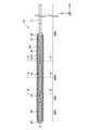
- FIG. 1 is an explanatory diagram showing a schematic configuration of the guidewire 1 of the first embodiment.
- the guide wire 1 is a medical device that is inserted into a biological lumen in each organ of the human body, such as a blood vessel system, a lymphatic system, a biliary system, a urinary system, an airway system, a digestive system, a secretory gland, and a reproductive system. be.
- the guidewire 1 may be inserted directly into the above-described biological lumen, or may be inserted into the biological lumen via an endoscope.
- the guidewire 1 comprises a core wire 10 , a distal junction 24 , an outer coil 30 and a proximal junction 52 .
- FIG. 1 shows a longitudinal section of the guide wire 1 along the axis O direction.
- the axis O coincides with the axis passing through the centers of the guidewire 1 and each component.
- the axis O may be different from each central axis of the guidewire 1 and each component.
- FIG. 1 illustrates XYZ axes that are orthogonal to each other.
- the X-axis corresponds to the longitudinal direction of the guidewire 1 (the direction of the axis O), the Y-axis corresponds to the height direction of the guidewire 1, and the Z-axis corresponds to the width direction of the guidewire 1.
- FIG. The left side ( ⁇ X axis direction) of FIG. 1 is called the “distal side” of the guide wire 1 and each component, and the right side (+X axis direction) of FIG. 1 is called the “proximal side” of the guide wire 1 and each component. call.
- the end located on the distal side is called the "tip", and the tip and the vicinity thereof are called the "tip".
- the end located on the proximal side is called the "base end”, and the base end and the vicinity thereof are called the “base end”.
- the distal side is inserted into the living body, and the proximal side is operated by an operator such as a doctor.
- the core wire 10 is an elongated member.
- the core wire 10 has a large-diameter portion 11, a reduced-diameter portion 12, a small-diameter portion 13, and a distal large-diameter portion 20 in order from the proximal side to the distal side.
- the large-diameter portion 11 is formed on the proximal end side of the core wire 10 .
- the large-diameter portion 11 has a substantially cylindrical shape with a substantially constant outer diameter, and is a portion having a larger outer diameter than the reduced-diameter portion 12 and the small-diameter portion 13 .
- substantially constant is synonymous with “substantially constant”, and means to be substantially constant while allowing fluctuations caused by manufacturing errors or the like.
- the large-diameter portion 11 is not covered with the outer coil 30 and is used when the operator grasps the guidewire 1 .
- the reduced diameter portion 12 is formed between the large diameter portion 11 and the small diameter portion 13 of the core wire 10 .
- the reduced-diameter portion 12 has a tapered shape in which the outer diameter gradually decreases from the base end side to the tip end side.
- the small-diameter portion 13 is formed between the tip large-diameter portion 20 and the small-diameter portion 12 of the core wire 10 .
- the small-diameter portion 13 has a substantially cylindrical shape with a substantially constant outer diameter, and is the portion with the smallest outer diameter of the core wire 10 .
- the outer diameter and length of each portion (large-diameter portion 11, reduced-diameter portion 12, small-diameter portion 13) of the core wire 10 can be arbitrarily determined.
- the tip large-diameter portion 20 is formed on the tip side of the core wire 10 .
- the tip large-diameter portion 20 has a substantially cylindrical shape with a substantially constant outer diameter.
- the tip large-diameter portion 20 is the first magnetized region MR1 magnetized on the tip side of the core wire 10 .
- a magnetized region is a region magnetized by application of an external magnetic field.
- the tip large-diameter portion 20 and the portion of the outer coil 30 disposed therearound are hatched in a dot pattern, and the hatching indicates magnetized portions. Also in FIG. 1 and subsequent figures, it is common that the dot-patterned hatching indicates the magnetized portion.
- the regions of the core wire 10 that are not magnetized on the proximal end side of the first magnetized region MR1 correspond to the non-magnetized region NR.
- the non-magnetized region is a region that is not magnetized by application of an external magnetic field, and may be slightly magnetized due to the influence of shape processing or the like.
- the material forming the tip large-diameter portion 20 can be arbitrarily determined as long as it is a magnetic material that is magnetized by applying an external magnetic field.
- examples of such materials include stainless steel undergoing martensitic transformation (e.g., SUS304, SUS316, SUS302, SUS444, SUS434, SUS630), martensitic stainless steel (e.g., SUS410), and ferritic stainless steel (e.g., , SUS430).
- the material forming the portion of the core wire 10 that corresponds to the non-magnetized region NR may be the same material as that of the tip large-diameter portion 20, or may be a non-magnetic material.
- the tip joint portion 24 joins the outer coil 30 and the tip of the core wire 10 (the tip of the tip large-diameter portion 20).
- the proximal joint portion 52 joins the outer coil 30 and the reduced diameter portion 12 of the core wire 10 .
- Any bonding agent such as metal solder such as silver brazing, gold brazing, zinc, Sn--Ag alloy, Au--Sn alloy, or epoxy-based adhesive may be used for joining at the distal joint portion 24 and the proximal joint portion 52. Adhesive can be used.
- the outer coil 30 has a substantially cylindrical shape with a substantially constant outer diameter from the proximal end to the distal end.
- the outer coil 30 is arranged so as to cover part of the tip large-diameter portion 20 , the small-diameter portion 13 and the reduced-diameter portion 12 of the core wire 10 .
- the outer coil 30 is a single-strand coil formed by winding one wire 31 into a single strand.
- the outer coil 30 may be a multi-strand coil formed by winding a plurality of strands in multiple strands, and may be formed by winding a single strand of a twisted wire obtained by twisting a plurality of strands.
- a single twisted wire coil may be used, or a multi-strand twisted wire coil may be formed by using a plurality of twisted wires obtained by twisting a plurality of strands and winding each twisted wire into multiple threads.
- the outer diameter and inner diameter of the outer coil 30 can be determined arbitrarily. Further, in the present embodiment, the outer coil 30 is made of a magnetic material that is magnetized by applying an external magnetic field, like the tip large diameter portion 20, but in other embodiments, it is made of a non-magnetic material. may
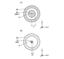
- FIG. 2 is a cross-sectional view of the guidewire 1.
- FIG. FIG. 2(A) shows a cross section taken along line AA of FIG.
- FIG. 2A shows a cross section of the core wire 10 at the position of the distal end large diameter portion 20 .
- the outer diameter r1 is the outer diameter of the tip large-diameter portion 20, which is the first magnetized region MR1.
- FIG. 2(B) shows a cross section taken along line BB of FIG.
- FIG. 2B shows a cross section of the core wire 10 at the position of the small diameter portion 13 .
- the outer diameter r2 is the outer diameter of the small diameter portion 13 that is the non-magnetized region NR. As shown in FIGS.
- the maximum value of the outer diameter r1 of the first magnetized region MR1 is the tip portion ( It is larger than the outer diameter r2 of the small diameter portion 13).
- both the tip large-diameter portion 20 and the small-diameter portion 13 are substantially columnar and have a circular cross section.
- the cross sections of the portion 20 and the small diameter portion 13 are elliptical, the length of the longest portion in any cross section is taken as the outer diameter.
- the distal end large-diameter portion 20 has a shape different from the substantially cylindrical shape (a shape in which the cross-sectional area of the cross section is not substantially constant)
- the longest outer diameter r1 among the outer diameters r1 in each cross section is the maximum.
- the diameter r2 be compared with the maximum value of the outer diameter r1.
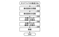
- FIG. 3 is a flow chart of the method for manufacturing the guidewire 1.
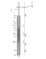
- FIG. 4A, 4B, and 4C are explanatory diagrams showing the manufacturing process of the guidewire 1.
- FIG. The XYZ axes illustrated at the lower right position in FIG. 4 are shared by each of FIGS. 4(A), (B) and (C).
- a rod-shaped member 10p1 is prepared (step S10).
- the rod-shaped member 10p1 is a base member of the core wire 10 (FIG. 1).
- the rod-shaped member 10p2 is formed by cutting the rod-shaped member 10p1 (step S20). Cutting is performed using a grinder or the like.
- the rod-shaped member 10p2 has a large-diameter portion 11, a reduced-diameter portion 12, a small-diameter portion 13, and a columnar portion 20p in order from the base end to the tip end.
- the cylindrical portion 20p is a base member of the tip large-diameter portion 20, and is the tip large-diameter portion 20 before being magnetized. That is, the rod-shaped member 10p2 is a core wire 10 having the shape of the core wire 10 but having a non-magnetized tip.
- the distal end of the cylindrical portion 20p is joined to the distal end of the outer coil 30 via the distal joint portion 24 (step S30), and the proximal joint portion 52 is inserted into the contracted portion.
- a portion of diameter portion 12 is joined to the proximal end of outer coil 30 (step S40).
- the columnar portion 20p is magnetized by applying an external magnetic field from a magnetizing device (not shown) to become the tip large-diameter portion 20 (step S50).
- the portion of the outer coil 30 arranged around the cylindrical portion 20p is also magnetized (FIG. 1).
- the magnetizing device may include, for example, a permanent magnet or an air-core coil that generates a magnetic field by applying an electric current. After the external magnetic field has been applied, the method of manufacturing the guidewire 1 is finished.
- the shape of the core wire 10 is integrally formed in the manufacturing process described with reference to FIG. 4, it may be formed separately. In such a case, a rod-shaped member having a large-diameter portion 11, a reduced-diameter portion 12, and a small-diameter portion 13 is produced by cutting, and then a cylindrical portion 20p (the base of the tip large-diameter portion 20) is attached to the tip of the rod-shaped member.
- the shape of the core wire 10 is formed by joining the members). Joining is performed by laser welding or soldering.
- the core wire 10 Since the volume per unit length of the tip large-diameter portion 20 (first magnetized region MR1) formed at the tip of the tip can be increased, the tip large-diameter portion 20 (first magnetized region MR1) can have a large magnetism.
- the unit length here means the unit length in the longitudinal direction of the core wire 10.
- the magnetic sensor placed outside the living body can easily detect the tip of the guide wire 1 inserted into the lumen of the body. can be improved.
- the improved detection accuracy makes it easier for the operator to grasp the movement of the distal end portion of the guide wire 1, so that the procedure can be performed with high accuracy and efficiency.
- the tip large-diameter portion 20 occupies a volume in the space inside the generally cylindrical outer coil 30 by forming the tip large-diameter portion 20 into a substantially cylindrical shape. Since it is made as large as possible, the magnetism imparted to the tip large-diameter portion 20 (first magnetized region MR1) can also be made large accordingly. On the other hand, since the outer diameter of the tip portion of the non-magnetized region NR is smaller than the maximum value of the outer diameter r1 of the tip large-diameter portion 20, the bending rigidity of the core wire 10 on the proximal side of the tip large-diameter portion 20 can be reduced. Therefore, the bendability of the guidewire 1 is maintained.
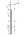
- FIG. 5 is an explanatory diagram showing a schematic configuration of the guidewire 1A of the second embodiment.
- the guidewire 1A of the second embodiment differs from the guidewire 1 of the first embodiment (FIG. 1) in that it includes an inner coil 40, a proximal joint 42, and a distal joint 44. .
- the inner coil 40 has a substantially cylindrical shape with a substantially constant outer diameter from the proximal end to the distal end.
- the inner coil 40 is a magnetized coil that covers the outer peripheral surface of the core wire 10 (small diameter portion 13).
- the inner coil 40 is joined to the core wire 10 (reduced diameter portion 13 ) and the outer coil 30 via proximal joints 42 and distal joints 44 . Note that the inner coil 40 does not have to be joined to the outer coil 30 .
- the inner coil 40 is a single coil formed by winding one wire 41 into a single strand, similar to the outer coil 30, but it may be a multiple coil or a single stranded wire. It may be a coil or a multi-stranded wire coil.
- the inner coil 40 is made of a magnetic material that is magnetized by applying an external magnetic field, similarly to the tip large-diameter portion 20 and the outer coil 30 .
- the tip large-diameter portion 20 and the portion of the outer coil 30 disposed therearound are magnetized.
- the coated portion of the core wire 10 covering the outer peripheral surface and the portion of the outer coil 30 corresponding to the position where the inner coil 40 exists in the X-axis direction are also magnetized. That is, in the second embodiment, the core wire 10 has the second magnetized region MR2 (FIG. 5) magnetized at a position spaced apart from the first magnetized region MR1 on the proximal side of the first magnetized region MR1. there is The second magnetized region MR2 includes a covered portion of the core wire 10 covered with the inner coil 40 and the inner coil 40 .
- a first non-magnetized region NR1 is provided between the first magnetized region MR1 and the second magnetized region MR2.
- NR2 is provided.
- a portion of the core wire 10 on the distal side of the covered portion covered with the inner coil 40 corresponds to the first non-magnetized region NR1, and a portion of the core wire 10 on the proximal side of the covered portion corresponds to the second non-magnetized region NR2. .
- FIG. 6 is a cross-sectional view of the guidewire 1A.
- FIG. 6A shows a cross section taken along line AA of FIG.
- FIG. 6B shows a cross section taken along line BB on the base end of the first non-magnetized region NR1 in FIG.
- FIG. 6(C) shows a cross section along line CC on the tip of the second non-magnetized region NR2 in FIG.
- the outer diameter r3 is the outer diameter of the second magnetized region MR2 and the outer diameter of the inner coil 40 as well.
- the outer diameter r4 is the outer diameter of the first non-magnetized region NR1 and also the outer diameter of the small diameter portion 13 .
- FIG. 6A shows a cross section taken along line AA of FIG.
- FIG. 6B shows a cross section taken along line BB on the base end of the first non-magnetized region NR1 in FIG.
- FIG. 6(C) shows a cross section along line CC on the tip of the second
- the outer diameter r5 is the outer diameter of the second non-magnetized region NR2 and also the outer diameter of the small-diameter portion 13 .
- the maximum value of the outer diameter r3 of the inner coil 40 as the second magnetized region MR2 is the outer diameter r4 of the base end portion of the first non-magnetized region NR1. and larger than the outer diameter r5 of the tip of the second non-magnetized region NR2.
- the tip of the non-magnetized region in the guidewire 1 of the first embodiment (the position of the BB line in FIG. 1 and its vicinity) is the same as that of the first non-magnetized region NR1 in the guidewire 1A of the second embodiment. It corresponds to the tip. Therefore, it can be said that the maximum value of the outer diameter r1 (FIG. 2) of the tip large-diameter portion 20 is larger than the outer diameter r4 (FIG. 6) of the tip portion of the first non-magnetized region NR1.
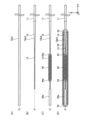
- FIGS. 7(A) to (D) are explanatory diagrams showing the manufacturing process of the guidewire 1A.
- the XYZ axes illustrated at the lower right position in FIG. 7 are shared by each of FIGS. 7(A) to (D).
- the method of manufacturing the guidewire 1A is similar to the flow chart shown in FIG. 3 and is described below.
- FIG. 7(A) after preparing the rod-shaped member 10p1 (corresponding to step S10 in FIG. 3), as shown in FIG. 7(B), the rod-shaped member 10p1 is cut. Thus, it becomes the rod-shaped member 10p3 (corresponding to step S20 in FIG. 3).
- the rod-shaped member 10p3 has a large-diameter portion 11, a reduced-diameter portion 12, and a small-diameter portion 13 in order from the base end to the tip end.
- the inner coil 40 is arranged at the position of the small diameter portion 13 from the tip side of the rod-shaped member 10p3 and joined via the joint portion 42p and the joint portion 44p.
- a rod-like member 10p4 is formed by joining the cylindrical portion 20p to the tip of the member 10p3. The joining at this time is also performed by laser welding or soldering.
- FIG. 7D the tip of the cylindrical portion 20p is joined to the tip of the outer coil 30 via the tip joint 24 (corresponding to step S30 in FIG. 3).
- portions of the outer coil 30 arranged around the cylindrical portion 20p and around the inner coil 40 are also magnetized. It should be noted that if the step of bonding the small diameter portion 13 and the inner coil 40 to the intermediate portion of the outer coil 30 is omitted from the above-described series of steps, the inner coil 40 is not bonded to the outer coil 30. can also be manufactured.
- the guide wire 1A of the second embodiment it is possible to provide the distal end portion of the guide wire 1A with a desired strength of magnetism, as in the first embodiment.
- the first magnetized region MR1 and the second magnetized region MR2 are separated by the first non-magnetized region NR1, so the position of the first magnetized region MR1 and It can be detected separately from the position of the second magnetized region MR2.
- the degree of curvature of the guide wire 1A in the range from the second magnetized region MR2 to the first magnetized region MR1 is grasped by the position of the first magnetized region MR1 and the position of the second magnetized region MR2 that are detected separately. can do.
- the maximum value of the outer diameter r3 of the inner coil 40 as the second magnetized region MR2 is larger than the outer diameter r4 at the proximal end of the first non-magnetized region NR1, Moreover, it is larger than the outer diameter r5 at the tip of the second non-magnetized region NR2. Therefore, it is possible to increase the volume of the second magnetized region MR2 per unit length while maintaining the flexibility of the core wire 10 . As a result, since the second magnetized region MR2 can have a large magnetism, the detection accuracy of the second magnetized region MR2 is improved. The bending degree of the guide wire 1A can be grasped with higher accuracy.
- the behavior of the guidewire 1A in the range from the second magnetized region MR2 to the first magnetized region MR1 is detected in real time by the magnetic sensor.
- grasping by grasping with the conventional method using contrast medium and radiography at regular timing, rather than grasping behavior only by using conventional methods for grasping behavior, radiation exposure by radiography You can reduce the amount.
- the guide wire 1A of the second embodiment when the first magnetized region MR1 has a stronger magnetism than the second magnetized region MR2, it is possible to accurately and efficiently perform a procedure in which it is important to grasp the behavior of the tip of the guide wire 1A. It is possible to advance the procedure well. Further, when the first magnetized region MR1 and the second magnetized region MR2 are given the same magnetism, the strength of the magnetism detected by the magnetic sensor from each region is proportional to the distance from each region. Therefore, it is possible to provide the guide wire 1A which makes it possible to grasp the position of each region most easily.
- the position of the second magnetized region MR2 can be easily grasped. For example, if the distal end portion of the guide wire 1A is inserted into one of the blood vessels on the far side from the branch position so that the second magnetized region MR2 is arranged at the branch position where the blood vessel branches, then another guide wire is inserted. is inserted into the other blood vessel on the far side from the branch position, the second magnetized region MR2 can be used as a marker for the branch position. It should be noted that even when another guide wire is being operated, the magnetic sensor can be used to determine in real time whether the previously inserted guide wire 1A is misaligned.
- FIG. 8 is an explanatory diagram showing a schematic configuration of the guidewire 1B of the third embodiment.
- the guidewire 1B of the third embodiment differs from the guidewire 1A of the second embodiment (FIG. 5) in that it includes a core wire 10b having a curved portion CV.
- the core wire 10b has a curved portion CV where the core wire 10b is curved in the first non-magnetized region NR1, which is the region between the first magnetized region MR1 and the second magnetized region MR2.
- the curved portion CV is also a portion where the axis of the guide wire 1B extending in a certain direction from the proximal side is curved. Since the core wire 10b has the curved portion CV, the operability of the distal end portion of the guidewire 1B is improved. For example, when the guidewire 1B is inserted into a blood vessel, blood vessel selectivity is improved.
- the guide wire 1B of the third embodiment As described above, it is possible to provide the distal end portion of the guide wire 1B with a desired strength of magnetism, as in the first embodiment. Further, according to the guide wire 1B of the third embodiment, the first magnetized region MR1 provided on the distal side of the bending portion CV and the second magnetized region MR2 provided on the proximal side of the bending portion CV are separated. The accuracy of distinguishing and detecting can be improved. By using the positions of the first magnetized region MR1 and the positions of the second magnetized regions MR2 that are separately detected, the three-dimensional movement of the tip of the guide wire 1B can be accurately grasped.
- the distal end side mainly deforms from the bending portion CV. Therefore, by tracking the position of the first magnetized region MR1 with reference to the position of the second magnetized region MR2 on the proximal side of the curved portion CV, the three-dimensional movement of the distal end portion of the guide wire 1B can be accurately grasped. It is possible. As a result, the operator can proceed with the procedure with high accuracy and efficiency.
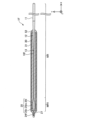
- FIG. 9 is an explanatory diagram showing a schematic configuration of a guidewire 1C of the fourth embodiment.
- the guidewire 1C of the fourth embodiment is mainly different from the guidewire 1A of the second embodiment (FIG. 5) in that it does not include the inner coil 40 and It differs in that it has a core wire 10c with 15.
- the intermediate large-diameter portion 14 is formed at the tip of the small-diameter portion 13 .
- the intermediate large-diameter portion 14 has a substantially cylindrical shape with a substantially constant outer diameter, and has a larger outer diameter than the small-diameter portion 13 and the tip-side small-diameter portion 15 formed at the tip of the intermediate large-diameter portion 14 . part.
- the intermediate large-diameter portion 14 and the portion of the outer coil 30 covering the intermediate large-diameter portion 14 in the X-axis direction are hatched in a dot pattern and are magnetized. It is shown that.
- the intermediate large-diameter portion 14 is the second magnetized region MR2 that is magnetized closer to the proximal side than the first magnetized region MR1.
- a distal large diameter portion 20 is formed on the distal end side of the distal small diameter portion 15 .
- FIG. 10 is a cross-sectional view of the guidewire 1C.
- FIG. 10A shows a cross section taken along line AA of FIG.
- FIG. 10B shows a cross section taken along line BB on the base end of the first non-magnetized region NR1 in FIG.
- FIG. 10(C) shows a cross section along line CC on the tip of the second non-magnetized region NR2 in FIG.
- the outer diameter r6 is the outer diameter of the second magnetized region MR2 and also the outer diameter of the intermediate large-diameter portion 14.
- the outer diameter r7 is the outer diameter of the first non-magnetized region NR1 and also the outer diameter of the tip-side small diameter portion 15. As shown in FIG.
- the outer diameter r8 is the outer diameter of the second non-magnetized region NR2 and also the outer diameter of the small diameter portion 13.
- the maximum value of the outer diameter r6 of the core wire 10c (intermediate large diameter portion 14) in the second magnetized region MR2 is the first non-magnetized region It is formed to be larger than the outer diameter r7 at the proximal end of NR1 and larger than the outer diameter r8 at the distal end of the second non-magnetized region NR2.
- FIG. 10C the maximum value of the outer diameter r6 of the core wire 10c (intermediate large diameter portion 14) in the second magnetized region MR2 is the first non-magnetized region It is formed to be larger than the outer diameter r7 at the proximal end of NR1 and larger than the outer diameter r8 at the distal end of the second non-magnetized region NR2.
- the tip of the guide wire 1C can have a desired strength of magnetism. Also, the volume of the second magnetized region MR2 per unit length can be increased without assembling a separate member to the core wire 10c. Therefore, as in the second embodiment and the like, since the second magnetized region MR2 can have a large magnetism, the detection accuracy of the second magnetized region MR2 is improved. The bending degree of the guide wire 1C in the range up to the region MR1 can be grasped with high accuracy.
- FIG. 11 is an explanatory diagram showing a schematic configuration of a guide wire 1D according to the fifth embodiment.
- the guidewire 1D of the fifth embodiment differs from the guidewire 1C (FIG. 9) of the fourth embodiment mainly in that it includes a core wire 10d having a constricted portion 21.
- FIG. 11 is an explanatory diagram showing a schematic configuration of a
- the constricted portion 21 is formed between the intermediate large-diameter portion 14d and the tip large-diameter portion 20d.
- the constricted portion 21 has a reduced-diameter portion 21l, an intermediate small-diameter portion 21m, and an enlarged-diameter portion 21n in order from the base end side toward the tip end side.
- the diameter-reduced portion 21 l is formed at the base end portion of the constricted portion 21 .
- the reduced diameter portion 21l is formed at the tip of the second magnetized region MR2.
- the diameter-reduced portion 21l is a portion whose outer diameter gradually decreases from the proximal side to the distal side.
- the intermediate small-diameter portion 21m is formed in the constricted portion 21 between the reduced-diameter portion 21l and the enlarged-diameter portion 21n.
- the intermediate small diameter portion 21m is a portion whose outer diameter decreases toward the center position in the X-axis direction.
- the enlarged diameter portion 21n is formed at the tip of the constricted portion 21 .
- the enlarged diameter portion 21n is formed at the base end portion of the first magnetized region MR1.
- the expanded diameter portion 21n is a portion whose outer diameter gradually expands from the base end side toward the tip end side.
- the tip of the guide wire 1D can have a desired strength of magnetism.
- the base end portion of the first magnetized region MR1 is formed with an enlarged diameter portion 21n whose outer diameter gradually increases from the base end side to the tip end side. Therefore, it is possible to suppress the bending of the base end portion of the first magnetized region MR1 by making it difficult to create a rigidity gap where the bending rigidity greatly changes at the base end portion of the first magnetized region MR1.
- the volume of the magnetized region MR1 can be increased.
- since the reduced-diameter portion 21l is formed at the tip of the second magnetized region MR2, bending of the tip of the second magnetized region MR2 can be suppressed.
- FIG. 12 is an explanatory diagram showing a schematic configuration of the guidewire 1E of the sixth embodiment.
- the guidewire 1E of the sixth embodiment differs from the guidewire 1D of the fifth embodiment (FIG. 11) mainly in that it includes a core wire 10e that does not have an intermediate large-diameter portion 14d.
- a large-diameter tip portion 20e is formed at the tip of the enlarged-diameter portion 23 formed at the tip of the small-diameter portion 13 in the core wire 10e.
- the enlarged diameter portion 23 is formed at the proximal end portion of the first magnetized region MR1, and the outer diameter gradually increases from the proximal end side to the distal end side.
- the portions of the core wire 10e that are not magnetized on the proximal side of the first magnetized region MR1 are , corresponds to the non-magnetized region NR.
- the guide wire 1E of the sixth embodiment as described above, it is possible to impart a desired strength of magnetism to the tip of the guide wire 1E, as in the first embodiment. Further, similarly to the sixth embodiment, it is possible to suppress the bending of the base end portion of the first magnetized region MR1 by making it difficult to create a rigidity gap where the bending rigidity greatly changes at the base end portion of the first magnetized region MR1. , the volume of the first magnetized region MR1 per unit length can be increased.
- FIG. 13 is an explanatory diagram showing a schematic configuration of the guide wire 1F of the seventh embodiment.
- the guide wire 1F of the seventh embodiment mainly differs from the guide wire 1E of the seventh embodiment (FIG. 12) in that it includes a core wire 10f having a different shape on the distal end side from the core wire 10e.
- the core wire 10f has an expanded portion 25 and a distal reduced diameter portion 27 in order from the base end side to the distal end side at the distal end portion.
- the expansion portion 25 is formed at the distal end portion of the small diameter portion 13 .
- the inflatable portion 25 has an enlarged diameter portion 25l, an intermediate large diameter portion 25m, and a reduced diameter portion 25n in order from the base end side to the tip end side.
- the enlarged diameter portion 25l is formed at the base end portion of the expansion portion 25. As shown in FIG.
- the expanded diameter portion 25l is a portion whose outer diameter gradually expands from the base end side toward the tip end side.
- the intermediate large-diameter portion 25m is formed between the enlarged-diameter portion 25l and the reduced-diameter portion 25n of the expansion portion 25. As shown in FIG.
- the intermediate large-diameter portion 25m is a portion whose outer diameter increases toward the center position in the X-axis direction.
- the reduced diameter portion 25n is formed at the distal end portion of the expansion portion 25. As shown in FIG.
- the diameter-reduced portion 25n is a portion whose outer diameter gradually decreases from the proximal side to the distal side.
- the tip reduced diameter portion 27 is formed at the tip of the expansion portion 25 .
- the tip reduced diameter portion 27 is formed at the tip of the first magnetized region MR1.
- the tip reduced diameter portion 27 is a portion whose outer diameter gradually decreases from the base end side to the tip end side.
- the expansion portion 25 and the reduced diameter portion 27 are hatched in a dot pattern to indicate that they are magnetized.
- the tip joint portion 24f has a substantially sharp shape formed so as to cover the tip reduced diameter portion 27, and joins the outer coil 30 and the tip of the core wire 10f (the tip of the tip reduced diameter portion 27). .
- the guide wire 1F of the seventh embodiment as described above, it is possible to impart a desired strength of magnetism to the tip of the guide wire 1F, as in the first embodiment.
- the increased diameter portion 25l and the decreased diameter portion 25n make it difficult for a rigidity gap in which the bending rigidity greatly changes to occur at the distal end portion and the proximal end portion of the first magnetized region MR1. Bending of the portion can be suppressed, and the volume of the first magnetized region MR1 per unit length can be increased by the intermediate large-diameter portion 25m.
- the distal end portion of the first magnetized region MR1 is formed with a distal reduced diameter portion 27 having an outer diameter that gradually decreases from the base end side to the distal end side. Therefore, when there is a lesion or the like clogging the lumen of the body into which the guidewire 1F is inserted, the guidewire 1F can be easily inserted into the lesion or the like.
- the leading end joining portion 24f which is formed in a substantially sharp shape using the tip reduced diameter portion 27 as a support, penetrates into the lesion or the like, thereby facilitating the insertion of the guide wire 1F into the lesion or the like.
- FIGS. 14A, 14B, and 14C are explanatory diagrams showing schematic configurations of guide wires 1Ga, 1Gb, and 1Gc of eighth to tenth embodiments.
- the guidewires 1Ga, 1Gb, and 1Gc of the eighth to tenth embodiments are different from the guidewire 1 of the first embodiment (FIG. 1) in that they include a core wire 10g having a different shape on the distal side from the core wire 10, and the outer coil 30 is provided with outer coils 30ga, 30gb, and 30gc, respectively.
- the configurations of the guide wires 1Ga, 1Gb and 1Gc are common in that they each include a core wire 10g, but differ in that they each include outer coils 30ga, 30gb and 30gc.
- the core wire 10g has a large-diameter portion 11, a reduced-diameter portion 12, and a small-diameter portion 13 in order from the proximal end to the distal end, but does not have the distal large-diameter portion 20 on the distal end.
- the outer coil 30ga like the outer coil 30 of the first embodiment, is a single coil made of a magnetic material that is magnetized by applying an external magnetic field.
- the outer coil 30ga is formed from strands 32 and 35 in order from the base end side to the tip side, and the diameter of the strand 35 is larger than that of the strand 32 .
- the outer coil 30ga is a coil formed by winding a single strand to which the strands 32 and 35 are connected.
- the outer coil 30ga has a substantially cylindrical shape (a shape having a substantially constant outer diameter in cross section).
- the outer coil 30ga has a magnetized region MR magnetized on the tip side. In guide wire 1Ga, the portion of core wire 10g located inside magnetized region MR is also magnetized. Further, the outer coil 30ga has a non-magnetized region NR that is not magnetized on the proximal side of the magnetized region MR.
- the magnetized region MR corresponds to the position where the wire 35 is wound in the outer coil 30ga. Also, the non-magnetized region NR corresponds to the position where the wire 32 is wound in the outer coil 30ga.
- the wire 35 forming the magnetized region MR in the outer coil 30ga is thicker than the wire 32 forming the distal end portion of the non-magnetized region NR, which is the region closer to the base end than the magnetized region MR.
- the volume of the magnetized region MR per unit length can be increased, so that the magnetized region MR can have a large magnetism.
- the magnetized region MR corresponds to the tip of the guide wire 1Ga, it is possible to provide the tip of the guide wire 1Ga with a desired strength of magnetism.
- the outer coil 30gb is formed of strands 32, 33, and 34 in order from the base end side to the tip side, and the diameter of the strand 33 is thicker than the strands 32 and 34. As shown in FIG.
- the outer coil 30gb is a coil formed by winding a single strand to which the strands 32, 33, and 34 are connected.
- the outer coil 30gb has a magnetized region MR magnetized at an intermediate position. Also in the guide wire 1Gb, the portion of the core wire 10g located inside the magnetized region MR is also magnetized.
- the outer coil 30gb has a first non-magnetized region NR1 that is not magnetized on the tip side of the magnetized region MR, and a second non-magnetized region NR2 that is not magnetized on the proximal side of the magnetized region MR. .
- the magnetized region MR corresponds to the position where the wire 33 is wound in the outer coil 30gb.
- the first non-magnetized region NR1 is located at the position where the wire 34 is wound in the outer coil 30gb
- the second non-magnetized region NR2 is located at the position where the wire 32 is wound in the outer coil 30gb.
- the wire 33 forming the magnetized region MR is thicker than the wire 32 forming the tip of the second non-magnetized region NR2, and forms the base of the first non-magnetized region NR1. Thicker than the wire 34 .
- the volume of the magnetized region MR per unit length can be increased, so that the magnetized region MR can have a large magnetism.
- the outer coil 30gc is formed from wire strands 32, 33, 34, and 35 in order from the base end side to the tip end side, and the diameter of the wire strands 33 and 35 is thicker than the wire strands 32 and 34. As shown in FIG.
- the outer coil 30gc is a coil formed by winding a single strand to which the strands 32, 33, 34, and 35 are connected.
- the outer coil 30gc has a first magnetized region MR1 magnetized on the tip side.
- the outer coil 30gc has a second magnetized region MR2 magnetized at a position spaced apart from the first magnetized region MR1 on the base end side of the first magnetized region MR1. Also in the guide wire 1Gc, portions of the core wire 10g arranged inside the first magnetized region MR1 and the second magnetized region MR2 are also magnetized. Furthermore, in the outer coil 30gc, between the first magnetized region MR1 and the second magnetized region MR2, a first non-magnetized region NR1 is provided, and on the base end side of the second magnetized region MR2, A second non-magnetized region NR2 is provided.
- the first magnetized region MR1 and the second magnetized region MR2 correspond to positions where the wires 35 and 33 of the outer coil 30gc are wound.
- the first non-magnetized region NR1 and the second non-magnetized region NR2 correspond to positions around which the wires 34 and 32 of the outer coil 30gc are wound.
- the wire 35 forming the first magnetized region MR1 is thicker than the wire 34 forming the tip of the first non-magnetized region NR1.
- the wire 33 forming the second magnetized region MR2 is thicker than the wire 34 forming the base end portion of the first non-magnetized region NR1, and forms the tip end portion of the second non-magnetized region NR2.
- the volume of the first magnetized region MR1 and the second magnetized region MR2 per unit length can be increased. It can have great magnetism.
- the outer coils 30ga, 30gb, and 30gc are single coils, but the outer coils 30ga, 30gb, and 30gc are multi-wound coils different from single-wound coils, single-wound twisted wire coils, or multi-wound coils. It may be a twisted wire coil.
- the diameter of the wire or twisted wire forming the portion corresponding to the position to be the magnetized region MR or the position to be the first (second) magnetized region MR1 (MR2) is used to form another portion.
- the configurations of the guide wires 1, 1A to 1F, 1Ga to Gc are illustrated.
- various changes in the configuration of the guidewire are possible.
- the portion closer to the proximal side than the distal large-diameter portion may have a constant outer diameter instead of the small-diameter portion, large-diameter portion, and reduced-diameter portion.
- the tip large-diameter portion which is the first magnetization region, may be formed on the tip side of the core wire 10 not including the tip.
- the guidewire may have more than two magnetized regions.
- the shape of the member forming the first magnetized region and the second magnetized region may be not substantially cylindrical but may be a shape that spreads out so as to fill the inner space of the coil. Specifically, it may have a shape having a projecting portion that fills a groove portion formed between wires wound as a coil.
- the outer coil and the inner coil may be made of a magnetic material at the positions where the external magnetic field is applied, and may be made of a non-magnetic material at the positions where the external magnetic field is not applied.
- Modification 2 The configurations of the guidewires 1, 1A to 1F, 1Ga to Gc of the first to tenth embodiments and each configuration of Modification 1 may be combined as appropriate.
- the portion where the outer diameter of the core wire changes (for example, the portion from the tip of the small diameter portion 13 to the tip large diameter portion 20) has a reduced diameter portion. or an enlarged diameter portion may be provided.
- the guide wires 1, 1C to 1F, 1Ga to Gc of the first, fourth to tenth embodiments may have the curved portions described in the third embodiment.
- the inner coil described in the second embodiment and the like may cover the outer peripheral surfaces of the intermediate large diameter portions 14 and 14d.
- the guide wires 1E and F of the sixth and seventh embodiments even if at least one of the inner coil described in the second embodiment and the like and the intermediate large-diameter portion described in the fourth embodiment and the like is provided, good.
- the guide wires 1Ga to Gc of the eighth to tenth embodiments may be provided with the core wires 10, 10c to f of the first and fourth to seventh embodiments instead of the core wire 10g, or the guide wires 1Ga to Gc of the second embodiment.
- the inner coil 40 may be provided with the core wire 10 whose outer peripheral surface is covered.
Landscapes
- Health & Medical Sciences (AREA)
- Life Sciences & Earth Sciences (AREA)
- Biophysics (AREA)
- Pulmonology (AREA)
- Engineering & Computer Science (AREA)
- Anesthesiology (AREA)
- Biomedical Technology (AREA)
- Heart & Thoracic Surgery (AREA)
- Hematology (AREA)
- Animal Behavior & Ethology (AREA)
- General Health & Medical Sciences (AREA)
- Public Health (AREA)
- Veterinary Medicine (AREA)
- Media Introduction/Drainage Providing Device (AREA)
Priority Applications (3)
| Application Number | Priority Date | Filing Date | Title |
|---|---|---|---|
| EP22907276.4A EP4450111A4 (en) | 2021-12-17 | 2022-12-05 | Guide wire |
| CN202280081357.XA CN118369130A (zh) | 2021-12-17 | 2022-12-05 | 导丝 |
| US18/735,242 US20240342439A1 (en) | 2021-12-17 | 2024-06-06 | Guide wire |
Applications Claiming Priority (2)
| Application Number | Priority Date | Filing Date | Title |
|---|---|---|---|
| JP2021-205355 | 2021-12-17 | ||
| JP2021205355A JP7699042B2 (ja) | 2021-12-17 | 2021-12-17 | ガイドワイヤ |
Related Child Applications (1)
| Application Number | Title | Priority Date | Filing Date |
|---|---|---|---|
| US18/735,242 Continuation US20240342439A1 (en) | 2021-12-17 | 2024-06-06 | Guide wire |
Publications (1)
| Publication Number | Publication Date |
|---|---|
| WO2023112748A1 true WO2023112748A1 (ja) | 2023-06-22 |
Family
ID=86774561
Family Applications (1)
| Application Number | Title | Priority Date | Filing Date |
|---|---|---|---|
| PCT/JP2022/044750 Ceased WO2023112748A1 (ja) | 2021-12-17 | 2022-12-05 | ガイドワイヤ |
Country Status (5)
| Country | Link |
|---|---|
| US (1) | US20240342439A1 (https=) |
| EP (1) | EP4450111A4 (https=) |
| JP (1) | JP7699042B2 (https=) |
| CN (1) | CN118369130A (https=) |
| WO (1) | WO2023112748A1 (https=) |
Citations (9)
| Publication number | Priority date | Publication date | Assignee | Title |
|---|---|---|---|---|
| US20070016131A1 (en) * | 2005-07-12 | 2007-01-18 | Munger Gareth T | Flexible magnets for navigable medical devices |
| US20070032746A1 (en) * | 2005-01-10 | 2007-02-08 | Stereotaxis, Inc. | Guide wire with magnetically adjustable bent tip and method for using the same |
| JP2013103075A (ja) | 2011-11-16 | 2013-05-30 | Olympus Corp | 誘導型医療システム |
| JP2017136158A (ja) * | 2016-02-02 | 2017-08-10 | テルモ株式会社 | カテーテル組立体 |
| JP2019520128A (ja) * | 2016-06-01 | 2019-07-18 | ベクトン・ディキンソン・アンド・カンパニーBecton, Dickinson And Company | 磁気領域を含む侵襲性の医用デバイスならびにシステムおよび方法 |
| JP2019520129A (ja) | 2016-06-01 | 2019-07-18 | ベクトン・ディキンソン・アンド・カンパニーBecton, Dickinson And Company | 磁気領域を含む侵襲性の医用デバイスならびにシステムおよび方法 |
| JP2019521742A (ja) * | 2016-06-01 | 2019-08-08 | ベクトン・ディキンソン・アンド・カンパニーBecton, Dickinson And Company | 永久磁石および磁化可能フィーチャーを利用する医療用デバイス、システム、および方法 |
| JP2020108757A (ja) | 2018-12-28 | 2020-07-16 | バイオセンス・ウエブスター・(イスラエル)・リミテッドBiosense Webster (Israel), Ltd. | バルーンを有する耳鼻咽喉科(ent)用中空ガイドワイヤ |
| US20200330730A1 (en) * | 2019-04-18 | 2020-10-22 | UNandUP, LLC. | Magnetically controlled medical devices for interventional medical procedures and methods of making and controlling the same |
Family Cites Families (4)
| Publication number | Priority date | Publication date | Assignee | Title |
|---|---|---|---|---|
| US5501228A (en) * | 1992-10-30 | 1996-03-26 | Scimed Life Systems, Inc. | Vibration sensing guide wire |
| US20040133130A1 (en) * | 2003-01-06 | 2004-07-08 | Ferry Steven J. | Magnetically navigable medical guidewire |
| US8784336B2 (en) * | 2005-08-24 | 2014-07-22 | C. R. Bard, Inc. | Stylet apparatuses and methods of manufacture |
| ES2556781T3 (es) * | 2010-09-29 | 2016-01-20 | St. Jude Medical Coordination Center Bvba | Alambre de guía de sensor |
-
2021
- 2021-12-17 JP JP2021205355A patent/JP7699042B2/ja active Active
-
2022
- 2022-12-05 EP EP22907276.4A patent/EP4450111A4/en active Pending
- 2022-12-05 CN CN202280081357.XA patent/CN118369130A/zh active Pending
- 2022-12-05 WO PCT/JP2022/044750 patent/WO2023112748A1/ja not_active Ceased
-
2024
- 2024-06-06 US US18/735,242 patent/US20240342439A1/en active Pending
Patent Citations (9)
| Publication number | Priority date | Publication date | Assignee | Title |
|---|---|---|---|---|
| US20070032746A1 (en) * | 2005-01-10 | 2007-02-08 | Stereotaxis, Inc. | Guide wire with magnetically adjustable bent tip and method for using the same |
| US20070016131A1 (en) * | 2005-07-12 | 2007-01-18 | Munger Gareth T | Flexible magnets for navigable medical devices |
| JP2013103075A (ja) | 2011-11-16 | 2013-05-30 | Olympus Corp | 誘導型医療システム |
| JP2017136158A (ja) * | 2016-02-02 | 2017-08-10 | テルモ株式会社 | カテーテル組立体 |
| JP2019520128A (ja) * | 2016-06-01 | 2019-07-18 | ベクトン・ディキンソン・アンド・カンパニーBecton, Dickinson And Company | 磁気領域を含む侵襲性の医用デバイスならびにシステムおよび方法 |
| JP2019520129A (ja) | 2016-06-01 | 2019-07-18 | ベクトン・ディキンソン・アンド・カンパニーBecton, Dickinson And Company | 磁気領域を含む侵襲性の医用デバイスならびにシステムおよび方法 |
| JP2019521742A (ja) * | 2016-06-01 | 2019-08-08 | ベクトン・ディキンソン・アンド・カンパニーBecton, Dickinson And Company | 永久磁石および磁化可能フィーチャーを利用する医療用デバイス、システム、および方法 |
| JP2020108757A (ja) | 2018-12-28 | 2020-07-16 | バイオセンス・ウエブスター・(イスラエル)・リミテッドBiosense Webster (Israel), Ltd. | バルーンを有する耳鼻咽喉科(ent)用中空ガイドワイヤ |
| US20200330730A1 (en) * | 2019-04-18 | 2020-10-22 | UNandUP, LLC. | Magnetically controlled medical devices for interventional medical procedures and methods of making and controlling the same |
Non-Patent Citations (1)
| Title |
|---|
| See also references of EP4450111A4 |
Also Published As
| Publication number | Publication date |
|---|---|
| US20240342439A1 (en) | 2024-10-17 |
| JP2023090411A (ja) | 2023-06-29 |
| CN118369130A (zh) | 2024-07-19 |
| JP7699042B2 (ja) | 2025-06-26 |
| EP4450111A4 (en) | 2025-10-01 |
| EP4450111A1 (en) | 2024-10-23 |
Similar Documents
| Publication | Publication Date | Title |
|---|---|---|
| JP5273820B2 (ja) | ガイドワイヤ | |
| JP4681551B2 (ja) | カテーテルに使用するガイドワイヤ | |
| US8994366B2 (en) | Magnetically tracked sensor | |
| WO2006078509A3 (en) | Guide wire with magnetically adjustable bent tip and method for using the same | |
| US20110301501A1 (en) | Guidewire | |
| US20230321409A1 (en) | Guide wire | |
| WO2023112748A1 (ja) | ガイドワイヤ | |
| JP7270047B2 (ja) | ガイドワイヤ、及び、ガイドワイヤの製造方法 | |
| JP7509908B2 (ja) | 医療用デバイス | |
| US20220331564A1 (en) | Guide wires | |
| US12083297B2 (en) | Guide wire | |
| JP7261879B2 (ja) | ガイドワイヤ | |
| CN211835745U (zh) | 导丝 | |
| CN102475936A (zh) | 医疗用导引线结构及其制作方法 | |
| JPH10309319A (ja) | カテーテル用ガイドワイヤ | |
| US11931535B2 (en) | Guide wire | |
| CN211705592U (zh) | 导丝 | |
| JP7021350B2 (ja) | ガイドワイヤ | |
| JP2026001753A (ja) | ガイドワイヤ | |
| JP2025101069A (ja) | ガイドワイヤ | |
| JP2025101070A (ja) | ガイドワイヤ | |
| JP2013135812A (ja) | ガイドワイヤ |
Legal Events
| Date | Code | Title | Description |
|---|---|---|---|
| 121 | Ep: the epo has been informed by wipo that ep was designated in this application |
Ref document number: 22907276 Country of ref document: EP Kind code of ref document: A1 |
|
| WWE | Wipo information: entry into national phase |
Ref document number: 202280081357.X Country of ref document: CN |
|
| WWE | Wipo information: entry into national phase |
Ref document number: 2022907276 Country of ref document: EP |
|
| NENP | Non-entry into the national phase |
Ref country code: DE |
|
| ENP | Entry into the national phase |
Ref document number: 2022907276 Country of ref document: EP Effective date: 20240717 |