WO2023112696A1 - 注出口構造、及び流動物収容容器 - Google Patents
注出口構造、及び流動物収容容器 Download PDFInfo
- Publication number
- WO2023112696A1 WO2023112696A1 PCT/JP2022/044374 JP2022044374W WO2023112696A1 WO 2023112696 A1 WO2023112696 A1 WO 2023112696A1 JP 2022044374 W JP2022044374 W JP 2022044374W WO 2023112696 A1 WO2023112696 A1 WO 2023112696A1
- Authority
- WO
- WIPO (PCT)
- Prior art keywords
- tubular portion
- spout structure
- hollow shaft
- tubular
- peripheral surface
- Prior art date
- Legal status (The legal status is an assumption and is not a legal conclusion. Google has not performed a legal analysis and makes no representation as to the accuracy of the status listed.)
- Ceased
Links
Images

Classifications
-
- B—PERFORMING OPERATIONS; TRANSPORTING
- B65—CONVEYING; PACKING; STORING; HANDLING THIN OR FILAMENTARY MATERIAL
- B65D—CONTAINERS FOR STORAGE OR TRANSPORT OF ARTICLES OR MATERIALS, e.g. BAGS, BARRELS, BOTTLES, BOXES, CANS, CARTONS, CRATES, DRUMS, JARS, TANKS, HOPPERS, FORWARDING CONTAINERS; ACCESSORIES, CLOSURES, OR FITTINGS THEREFOR; PACKAGING ELEMENTS; PACKAGES
- B65D47/00—Closures with filling and discharging, or with discharging, devices
- B65D47/36—Closures with frangible parts adapted to be pierced, torn or removed, to provide discharge openings
-
- B—PERFORMING OPERATIONS; TRANSPORTING
- B65—CONVEYING; PACKING; STORING; HANDLING THIN OR FILAMENTARY MATERIAL
- B65D—CONTAINERS FOR STORAGE OR TRANSPORT OF ARTICLES OR MATERIALS, e.g. BAGS, BARRELS, BOTTLES, BOXES, CANS, CARTONS, CRATES, DRUMS, JARS, TANKS, HOPPERS, FORWARDING CONTAINERS; ACCESSORIES, CLOSURES, OR FITTINGS THEREFOR; PACKAGING ELEMENTS; PACKAGES
- B65D51/00—Closures not otherwise provided for
- B65D51/18—Arrangements of closures with protective outer cap-like covers or of two or more co-operating closures
- B65D51/20—Caps, lids, or covers co-operating with an inner closure arranged to be opened by piercing, cutting, or tearing
- B65D51/22—Caps, lids, or covers co-operating with an inner closure arranged to be opened by piercing, cutting, or tearing having means for piercing, cutting, or tearing the inner closure
-
- B—PERFORMING OPERATIONS; TRANSPORTING
- B65—CONVEYING; PACKING; STORING; HANDLING THIN OR FILAMENTARY MATERIAL
- B65D—CONTAINERS FOR STORAGE OR TRANSPORT OF ARTICLES OR MATERIALS, e.g. BAGS, BARRELS, BOTTLES, BOXES, CANS, CARTONS, CRATES, DRUMS, JARS, TANKS, HOPPERS, FORWARDING CONTAINERS; ACCESSORIES, CLOSURES, OR FITTINGS THEREFOR; PACKAGING ELEMENTS; PACKAGES
- B65D75/00—Packages comprising articles or materials partially or wholly enclosed in strips, sheets, blanks, tubes or webs of flexible sheet material, e.g. in folded wrappers
- B65D75/52—Details
- B65D75/58—Opening or contents-removing devices added or incorporated during package manufacture
- B65D75/5861—Spouts
Definitions
- the present invention relates to a spout structure and a fluid storage container.
- a configuration is known in which, by deeply attaching a cap equipped with a piercing tool to a container in which a fluid is contained and whose opening is sealed, the seal can be broken by the piercing tool.
- Cited Document 1 there is a cap that is screwed onto a mouth plug portion 31 of a tube-shaped container 30 to which a blind lid 32 is attached.
- a cap 10 with a piercer is described that includes a piercer (shaft portion) 16 capable of forming a hole for a discharge passage in the lid 32 .
- an object of one aspect of the present invention is to provide a spout structure that can prevent contents from leaking when the seal is broken at the start of use.
- one aspect of the present invention is a spout structure for discharging a fluid contained in a container body sealed with a closing member, the spout structure being positionally fixed with respect to the closing member. and a second tubular portion that overlaps the first tubular portion in the axial direction and moves relative to the first tubular portion in the axial direction, wherein the second tubular portion is the A hollow shaft portion disposed inside the first cylindrical portion, the hollow shaft portion having a piercing tool that can pierce the closing member by the relative movement, and the second cylindrical portion with respect to the first cylindrical portion.
- a spout structure that can prevent the contents from leaking when the seal is broken at the start of use.
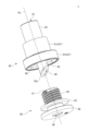
- FIG. 4 is an exploded view of a spout structure according to an embodiment of the invention
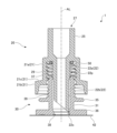
- Fig. 3 is a cross-sectional view of the spout structure before use
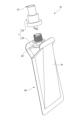
- FIG. 4 is a perspective view showing the spout structure together with the fluid container.
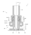
- Fig. 3 is a cross-sectional view of the spout structure just prior to breaking through the closure member
- FIG. 5 is an enlarged view of a sealing portion in FIG. 4
- Fig. 3 is a cross-sectional view of the spout structure after breaking through the closure member
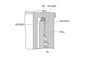
- FIG. 11 is a cross-sectional view of a spout structure according to a modified example
- FIG. 8 is an enlarged view of a sealing portion in FIG. 7
- FIG. 11 is a cross-sectional view of a spout structure according to another variant
- FIG. 10 is an enlarged view of a sealing portion in FIG. 9;
- FIG. 1 and 2 show a spout structure 1 according to an embodiment of the present invention.
- FIG. 1 is an exploded perspective view of the spout structure 1 viewed obliquely from below
- FIG. 2 is an axial cross-sectional view of the spout structure 1.
- FIG. 3 shows a perspective view showing the spout structure 1 together with the fluid containing portion 40. As shown in FIG.
- the pouring spout structure 1 is attached to a fluid containing part 40 in which a fluid is stored (FIG. 3). It is configured to be able to move from the inside of the fluid containing portion 40 to the outside through it. Further, the spout structure 1 may be connected to any desired known dispenser mechanism (such as a pump mechanism), an internal plug such as a pointed internal plug, a nozzle, or the like. As a result, the ejection device can be constructed, and the user can use the ejection device by ejecting the fluid to the outside according to a desired ejection method.
- a dispenser mechanism such as a pump mechanism
- an internal plug such as a pointed internal plug, a nozzle, or the like.
- the spout structure 1 includes a first tubular portion 30 and a second tubular portion that covers the first tubular portion 30 and is relatively movable with respect to the first tubular portion 30 in the axial direction. a part 20;
- the fluid contained in the fluid containing portion 40 can flow out through the spout structure 1 , more specifically through the opening 27 at the end of the second tubular portion 20 .
- the fluid containing portion 40 may be a pouch container, for example, a container in which the peripheral edges of two films or sheets are bonded together and the contents are contained in the portion surrounded by the peripheral edges.
- the fluid containing portion 40 may be of other forms, such as a tubular container formed by injection molding or casting.
- the material of the film that constitutes the fluid containing portion 40 may be a resin film, a laminate film composed of a plurality of resin films, or a laminate film containing a metal film and a resin film.
- the closing member 42 is provided at the mouth of the fluid container 40, that is, at a place where the fluid flows out during use.
- the closing member 42 is not particularly limited as long as it seals the fluid storage container 10 and can be broken by a piercing tool (described later) at the start of use, but at least the portion to be broken is a film or a sheet preferably in the form of
- the closing member 42 may be made of the same material as the material of the fluid containing portion 40, or may be made of a different material.
- the spout structure 1 according to this embodiment and the fluid accommodating part 40 to which the spout structure 1 is attached may constitute the fluid accommodating container 10 .
- the fluid storage container 10 can be used alone, it can be suitably used as a refill container housed in a separate outer package.
- a fluid may be a liquid, such as a liquid or a liquid mixture.
- the fluid may be, for example, a solution, a dispersion such as emulsion or suspension, or may be in a state called gel, slurry, paste, cream or the like.
- the fluid may contain powder, may consist primarily of powder, or may consist essentially of or consist of powder.
- the fluid may be a mixture of the fluid and a gas such as nitrogen, a rare gas, air, etc., and stored in a container in the form of foam. It may be one that is mixed and discharged in the form of foam.
- the fluid may be in a state of having a viscosity similar to or lower than that of water, or may be in the form of a paste or cream having a viscosity higher than that of water.
- Fluids include skin care products such as lotion, milky lotion, face cream, serum, facial cleanser, and cleansing agent, or makeup cosmetics such as basic cosmetics, foundation, makeup base, concealer, liquid eye shadow, liquid cheek, and liquid lip products.
- personal care products such as sunscreens, hand soaps, body soaps, hair shampoos, hair dyes, styling agents, hand creams, body creams and body lotions, fragrance products and the like.
- the fluid is not particularly limited as long as it has fluidity, and in addition to the above cosmetics, it may be foods (for example, seasonings), paints, adhesives, and the like.
- the spout structure 1 includes a first tubular portion 30 attached to the closing member 42 and a second tubular portion 20 provided to cover the first tubular portion 30 . ing.
- the extending direction of the axis AL of the spout structure 1 is also the axial direction of the first tubular portion 30 and the axial direction of the second tubular portion 20 .
- the axial side of the spout structure 1 that is closer to the closing member 42 is referred to as the "lower side”
- the opposite side, ie, the side that is closer to the opening 27 of the second tubular portion 20 is referred to as the "upper side”.
- the first tubular portion 30 has a first tubular portion main body 31 , and a flange-shaped bottom portion (base portion) 36 is formed at the lower end of the first tubular portion main body 31 .
- the lower surface of the bottom portion 36 is in contact with and adhered to the surface of the closing member 42 .
- the opening 38 on the lower side of the first tubular portion 30 is covered with the closing member 42 before use is started.
- the second cylindrical portion 20 is attached to the first cylindrical portion 30 by screwing. More specifically, a male threaded portion 39 is formed on the outer surface of the first cylindrical portion 30 , and the female threaded portion 29 formed inside the second cylindrical portion 20 is engaged with the male threaded portion 39 . match.
- the second tubular portion 20 can move relative to the first tubular portion 30 along the axial direction when it is screwed into the first tubular portion 30 .
- the second cylinder portion 20 includes a cover cylinder 21 and a hollow shaft portion 22 arranged inside the cover cylinder 21 and connected to the cover cylinder 21 on the upper side. Further, the cover cylinder 21 has a main portion 21a having a female threaded portion 29 formed on the inner surface thereof, and a large diameter portion 21b having an inner diameter and an outer diameter larger than those of the main portion 21a. A space (gap) is formed between the cover tube 21 and the hollow shaft portion 22, and a part of the first tube portion 30 is inserted into this space. Further, the hollow shaft portion 22 is adapted to be inserted inside the first tubular portion 30 .
- a passage along the axial direction is formed inside the hollow shaft portion 22 of the second tubular portion 20, and the fluid can be poured out or flowed out of the fluid storage container 10 through this passage.
- the hollow shaft portion 22 has an upper portion 22a with a larger outer diameter and a lower portion 22b with a smaller outer diameter than the upper portion 22a.
- the lower surface of the hollow shaft portion 22 is inclined with respect to a surface orthogonal to the axial direction. That is, it is cut at an angle to a plane orthogonal to the axial direction.
- a lower tip 22s which is a tip on the lower side of the hollow shaft portion 22, is formed, and when an arbitrary plane is brought closer, the lower tip 22s can contact the plane at a point or in a small area. It's becoming The hollow shaft portion 22 having such a lower tip 22s functions as a piercing tool that can pierce the closing member 42. As shown in FIG.
- an extended tubular portion 25 is formed above the cover tubular 21 and the hollow shaft portion 22 . Since the axial passage in the extension tube portion 25 communicates with the passage in the hollow shaft portion 22, when the user tries to take out the fluid after the piercing action, the fluid will pass through the hollow shaft. 22 and then through the extension tube 25 and out of the spout structure 1 .
- the dispenser mechanism is connected to the second cylindrical portion 20, the fluid contained in the fluid container 40 is discharged through the spout structure 1 according to the present embodiment and subsequently through the dispenser mechanism. It is discharged out of the device.
- the inner diameter of the extension cylinder portion 25 is larger than the inner diameter of the hollow shaft portion 22 (the inner diameter at the upper end of the hollow shaft portion 22), so that the discharge from the opening 27 is performed smoothly.
- the inner diameter of the extension cylinder portion 25 may be the same as the inner diameter of the hollow shaft portion 22 .
- the material forming the first cylindrical portion 30 and the second cylindrical portion 20 is not particularly limited, it is preferably resin.
- resins include polyethylene (PE), polypropylene (PP), polyethylene terephthalate (PET), polybutylene terephthalate (PBT), polystyrene (PS), and polylactic acid (PLA), and combinations thereof.
- the resins used for the first tubular portion 30 and the second tubular portion 20 may be the same, or may be different resins.
- FIG. 2 already referred to, shows the spout structure 1 in a state prior to the start of use of the fluid.
- the second tubular portion 20 partially covers the first tubular portion 30, but is not yet screwed together.
- the hollow shaft portion 22 of the second tubular portion 20 is arranged inside the first tubular portion 30 , but the lower tip 22 s does not reach the closing member 42 .
- the lower end of the upper portion 22a of the hollow shaft portion 22 reaches the upper edge 37 of the first cylindrical portion 30 or slightly overlaps the upper edge 37 in the axial direction.
- FIG. 4 shows a state in which the lower end 22s of the hollow shaft portion 22 of the second tubular portion 20 is in contact with the closing member 42. As shown in FIG.
- the hollow shaft portion (breaking tool) 22 of the second cylindrical portion 20 breaks through the closing member 42, and the closing member A notch is made at 42 (Fig. 6).
- the lower end portion of the hollow shaft portion 22 does not have a surface orthogonal to the axial direction, but has a surface cut obliquely to the surface orthogonal to the axial direction, and the lower tip 22s is formed. It is easy to concentrate pressure. Therefore, the closing member 42 containing a film can be easily broken through by the hollow shaft portion 22 .
- the hollow shaft portion 22 includes the upper portion 22a and the lower portion 22b having different outer diameters.
- the breakthrough operation of the closing member 42 by the portion 22 can be made more stable.
- the outer diameter of the lower portion 22b, which contacts the closing member 42 and actually performs the initial movement of breaking through the closing member 42, is smaller, the pressure at the time of breaking through can be increased more reliably, which is preferable.
- the inner diameters of the upper portion 22a and the lower portion 22b are the same, and more specifically, the diameter of the passage for the fluid formed in the hollow shaft portion 22 is constant.
- the inner diameters of the upper portion 22a and the lower portion 22b may change along the way depending on the characteristics of the fluid, the type of pouring, etc., as long as the function of the spout structure 1 for pouring out the fluid is not hindered. .
- the state shown in FIG. 6 is a state in which the second tubular portion 20 is rotated and moved downward, and the breakthrough of the closing member 42 by the hollow shaft portion 22 is completed.
- the notch in the closing member 42 is enlarged and a hole is formed in the closing member 42 .
- the user unintentionally moves the fluid storage container 10 itself, or impacts or impacts the fluid storage container 10.
- pressure is applied.
- the fluid may enter the spout structure from the fluid containing portion 40 through the closing member 42 .
- the fluid may flow out or be discharged to the outside through the spout structure in the spout structure of the conventional configuration. For example, it may flow out or be discharged to the outside through the space between the hollow shaft portion of the second tubular portion and the first tubular portion, and further through the threaded portion between the cover tubular portion and the first tubular portion. .
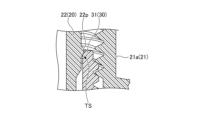
- a tight engagement TS is formed between the second tubular portion 20 and the first tubular portion 30 .
- Such close engagement between the second tubular portion 20 and the first tubular portion 30 prevents the fluid from passing between the second tubular portion 20 and the first tubular portion 30 to the outside.
- the hollow shaft portion 22 (upper portion 22a) of the second cylindrical portion 20 is formed with a convex portion 22p that protrudes from the outer peripheral surface of the hollow shaft portion 22, and the convex portion 22p serves as the first cylindrical portion. 30 and the tight engagement TS is formed (FIG. 4).
- FIG. 5 shows an enlarged view of the portion where the close engagement TS is formed in FIG.
- the protrusion 22p may have a size that slightly protrudes radially outward from the position of the inner peripheral surface of the first tubular portion 30 when viewed from above or in cross section.
- the second tubular portion 20 is press-fitted into the opening of the first tubular portion 30 when the second tubular portion 20 moves downward.
- the height of the convex portion 22p depends on the material, dimensions, etc. of the second cylindrical portion 20 and/or the first cylindrical portion 30, but the hollow shaft portion 22, preferably 0.01 to 0.5 mm, more preferably 0.03 to 0.3 mm.
- the convex portion 22p may be formed continuously over the outer peripheral surface of the hollow shaft portion 22. That is, the convex portion 22p may be an annular convex portion formed along the circumferential direction of the hollow shaft portion 22 . Thereby, leakage of the fluid can be prevented over the circumferential direction. Moreover, it is preferable that the annular convex portion is formed along a plane orthogonal to the axial direction.
- the timing at which the convex portion 22p and the first cylindrical portion 30 contact preferably closely
- the timing of forming the engagement TS may be at least the timing when the hollow shaft portion 22 begins to break through the closing member 42, or may be the timing when the hollow shaft portion 22 (lower tip 22s) contacts the closing member 42 (FIG. 4). ).
- the timing at which the closing member 42 starts breaking through is determined by the material of the closing member 42 , the shape of the lower tip 22 s, and the diameter of the opening 38 on the lower side of the first tubular portion 30 .
- the length in the axial direction from the top of the convex portion 22p to the lower end (lower tip 22s) of the hollow shaft portion 22 is the length of the first tubular portion 30, that is, from the upper edge 37 to the lower surface of the bottom portion 36. It may be less than or equal to the length (to the upper surface of the closure member 42), or may be approximately equal or equal to the length of the first tubular portion 30.
- the convex portion 22p at a position such that the close engagement TS is formed at the timing when the closing member 42 starts breaking through or just before that, the pressure in the spout structure 1 increases. This is preferable from the viewpoint of smooth operation.
- the convex portion 22p is formed integrally with the hollow shaft portion 22 (the second cylindrical portion 20), but forms a close engagement TS with the first cylindrical portion 30. If possible, the convex portion 22p may be formed separately from the hollow shaft portion 22 . Moreover, as shown in FIGS. 2, 4 and 5, the convex portion 22p may be provided at one position when viewed in the axial direction, or may be provided at a plurality of positions in the axial direction.
- the downward movement limit of the second cylindrical portion 20 is the connection portion between the cover cylinder 21 and the hollow shaft portion 22 of the second cylindrical portion 20. may be up to contacting the upper edge 37 of the first tubular portion 30 .
- the upper edge 37 of the first tubular portion 30 acts as a stopper to prevent the second tubular portion 20 from proceeding further downward.
- a packing (O-ring) or an elastic ring member 50 is provided on the lower side of the connecting portion between the cover cylinder 21 and the hollow shaft portion 22 of the second cylinder portion 20 (FIGS. 2, 4, 4 and 5). and FIG. 6). In that case, the second tubular portion 20 can move downward until the upper edge 37 of the first tubular portion 30 abuts against the elastic ring member 50 .
- a limiting member 35 projecting radially from the outer peripheral surface of the first cylindrical portion 30 may be formed in the first cylindrical portion 30 at a position lower than the male screw portion 39 (see FIGS. 1 to 4). 4, Fig. 6).
- the restricting member 35 comes into contact with the lower surface of the stepped portion 22c formed between the main portion 21a and the large diameter portion 21b of the cover cylinder 21.
- the restricting member 35 can also act as a stopper that stops the advancement of the second tubular portion 20 .
- the upper edge 37 of the first cylindrical portion 30 contacts the elastic ring member 50 before the limit member 35 contacts the lower surface of the stepped portion 22c. can prevent excessive load.
- the closing member 42 may be a film-like or sheet-like member formed as part of the fluid containing portion 40 .
- the closing member 42 may be, for example, a metal thin film sheet, an aluminum laminate sheet, or the like. Also, the film-like or sheet-like closure member 42 may be flat or may be curved and cup-shaped.
- FIG. 7 shows a modification of the close engagement TS between the second tubular portion and the first tubular portion.
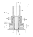
- the spout structure 201 shown in FIG. 7 has the same basic configuration as the spout structure 1 according to the example described with reference to FIGS. 2 and 4-6.
- the spout structure 201 includes a first tubular portion 230 that is positionally fixed with respect to the closing member 42 , and a first tubular portion 230 that is screwed into the first tubular portion 230 and is axially movable relative to the first tubular portion 230 .
- 2 cylinder part 220 is provided.
- the points that the second cylindrical portion 220 has a cover cylinder 221 and a hollow shaft portion 222, that the hollow shaft portion 222 can break through the closing member 42, etc.
- the tight engagement TS is not formed by the convex portion protruding from the hollow shaft portion and the first cylindrical portion, but by the convex portion protruding from the inner peripheral surface of the first cylindrical portion 230. 231p and the hollow shaft portion 222 of the second tubular portion 220, which is different from the spout structure 1.
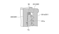
- FIG. 8 shows an enlarged view of the tight engagement TS portion of FIG.
- the convex portion 231p shown in FIGS. 7 and 8 is formed on the inner peripheral surface of the first cylindrical portion 230 in the circumferential direction in the same manner as the above-described convex portion 22p (FIGS. 2 and 4 to 6) in the spout structure 1. It may be an annular protrusion that is rounded. The protrusion 231p may have a size that slightly protrudes radially inward from the position of the outer peripheral surface of the second cylindrical portion 220 when viewed from above or in cross section. As a result, when the second tubular portion 220 moves downward, the second tubular portion 220 and the first tubular portion 230 are press-fitted into engagement.
- the axial position of the convex portion 231p (or the top portion of the convex portion 231p) forms close engagement with the outer peripheral surface of the hollow shaft portion 222 at or before the timing when the closing member 42 starts breaking through. It may be located at any position on the first tubular portion 30 as long as it is possible.
- FIG. 9 shows another modified example of the tight engagement TS between the second tubular portion and the first tubular portion.
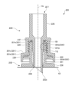
- the spout structure 301 shown in FIG. 9 has the same basic configuration as the spout structure 1 (FIGS. 2 and 4 to 6) described above.
- the spout structure 301 includes a first tubular portion 330 that is positionally fixed with respect to the closing member 42 , and a first tubular portion 330 that is screwed into the first tubular portion 330 and is axially movable relative to the first tubular portion 330 . 2 cylinder part 320 is provided.
- FIG. 10 shows an enlarged view of the tight engagement TS portion of FIG.
- the convex portion 321p formed on the inner peripheral surface of the main portion 321a of the cover tube 321 of the second tubular portion 320 is engaged with the outer peripheral surface of the first tubular portion 30. Due to such close engagement TS, the flow of the fluid is suppressed at the position where the convex portion 321p is formed. Even if the fluid enters the spout structure 301 , it is possible to prevent the fluid from leaking out of the spout structure 301 .
- the convex portion 321p is formed in an area where the male threaded portion 339 is not formed on the outer peripheral surface of the first cylindrical portion 30, for example, a male thread. It is preferable to form it above the region where the portion 339 is formed.
- the close engagement TS is formed by the cover tube 321 and the first tube portion 330, so that the force is likely to be applied to the cover tube 321 among the second tube portions 320. Force is less likely to be applied to the shaft portion 322 . Therefore, in this example, when the closing member 42 is broken through, the position of the hollow shaft portion 322 can be prevented from being displaced, pressure can be stably applied to the closing member 42, and the break-through operation becomes smooth. In that respect, it is preferable.
- the form of the close engagement between the first tubular portion and the second tubular portion is such that a close engagement capable of preventing outflow of the fluid can be formed between the first tubular portion and the second tubular portion.
- a convex portion may be formed on the outer peripheral surface of the first cylindrical portion 330 instead of forming the convex portion on the cover cylinder 321 side of the second cylindrical portion 320 .
- the inner peripheral surface of the large diameter portion (21b, 221b, 321b) of the cover cylinder (32, 221, 321) is not the main portion (21a, 221a, 321a). and a restrictive member (35, 235, 351).
- the large diameter portions (21b, 221b, 221b, 221b, 221b, 221b, 221b, 221b, 221b, 221b, 221b, 221b, 221b, 221b, 221b, 221b, 221b, 221b, 221b, 221b, 221b, 221b, 221b, 221b, 221b, 221b, 221b, 221b, 221b, 221b, 221b, 221b, 221b, 221b, 221b, 221b, 221b, 221b, 221b, 221b, 221b, 221b, 221b, 221b, 221b, 221b, 221b, 221b, 221b, 221b, 221b, 221b, 221b, 221b, 221b, 221b, 221b, 221b, 221b, 221b, 221b, 221b, 221
Landscapes
- Engineering & Computer Science (AREA)
- Mechanical Engineering (AREA)
- Closures For Containers (AREA)
Abstract
Description
20、220、320 第2筒部
21、221、321 第2筒部のカバー筒
21a、221a、321a カバー筒の主部
21b、221b、321b カバー筒の大径部
21c、221c、321c カバー筒の段部
22、222、322 第2筒部の中空軸部
22a、222a 中空軸部の上部
22b、222b 中空軸部の下部
22p、231p、321p 凸部
25、225、325 第2筒部の延長筒部
27、227、327 第2筒部の開口
29、229、329 第2筒部の雌ネジ部
30、230、330 第1筒部
31、231、331 第1筒部の本体
35、235、335 第1筒部の制限部材
36、236、336 第1筒部の底部
37、237、337 第1筒部の上縁
38、238、338 第1筒部の下側の開口
39、239、339 第1筒部の雄ネジ部
40 流動物収容部
41 収容部本体
42 閉鎖部材
50 弾性リング部材(Oリング)
TS 密係合
Claims (11)
- 閉鎖部材で封止された収容部に収容された流動物を吐出させるための注出口構造であって、
前記閉鎖部材に対して位置固定されている第1筒部と、
前記第1筒部に軸線方向で重なり、且つ当該第1筒部に対して軸線方向に相対移動な第2筒部とを備え、
前記第2筒部が、前記第1筒部の内側に配置された中空軸部を有し、当該中空軸部が、前記相対移動によって前記閉鎖部材を突き破り可能な突き破り具を有し、
前記第1筒部に対する前記第2筒部の前記相対移動の際に、前記第1筒部と前記第2筒部との間に密な係合が形成される、注出口構造。 - 前記密な係合が、前記第1筒部と、前記第2筒部の前記中空軸部との間に形成される、請求項1に記載の注出口構造。
- 前記中空軸部の外周面に周方向にわたって形成された環状凸部と、前記第1筒部の内周面とが密に係合する、請求項2に記載の注出口構造。
- 前記第1筒部の内周面に周方向にわたって形成された環状凸部と、前記中空軸部の外周面とが密に係合する、請求項2に記載の注出口構造。
- 前記第2筒部が、前記第1筒部の外側に配置されるカバー筒を備え、
前記密な係合が、前記第1筒部と、前記第2筒部の前記カバー筒との間に形成される、請求項1に記載の注出口構造。 - 前記第1筒部が、当該第1筒部の外周面から径方向に突出する、前記第2筒部の前記閉鎖部材に近付く動きを制限する制限部材を備え、
前記密な係合が、前記制限部材と、前記カバー筒の内周面との間に形成される、請求項5に記載の注出口構造。 - 前記第1筒部の前記第2筒部に対する前記相対移動の際に、少なくとも前記突き破り具が前記閉鎖部材に接した時点で前記密な係合が形成される、請求項1に記載の注出口構造。
- 前記第2筒部が、前記第1筒部の外側に配置されるカバー筒を備え、
前記第1筒部の外周面と、前記第2筒部の前記カバー筒の内周面とが螺合する、請求項1に記載の注出口構造。 - 前記中空軸部と前記カバー筒とが、前記閉鎖部材から離れた側の端部で接続されて接続部分が形成され、前記接続部分に弾性リング部材が配置され、当該弾性リング部材に前記第1筒部が密に当接可能である、請求項8に記載の注出口構造。
- 前記閉鎖部材が、フィルム状部分を含む、請求項1に記載の注出口構造。
- 請求項1から10のいずれか一項に記載の注出口構造と、
前記注出口構造が取り付けられた収容部とを備えた、流動物収容容器。
Priority Applications (2)
| Application Number | Priority Date | Filing Date | Title |
|---|---|---|---|
| CN202280075965.XA CN118234670A (zh) | 2021-12-15 | 2022-12-01 | 注出口结构、以及流动物收容容器 |
| JP2023567679A JPWO2023112696A1 (ja) | 2021-12-15 | 2022-12-01 |
Applications Claiming Priority (2)
| Application Number | Priority Date | Filing Date | Title |
|---|---|---|---|
| JP2021203152 | 2021-12-15 | ||
| JP2021-203152 | 2021-12-15 |
Publications (1)
| Publication Number | Publication Date |
|---|---|
| WO2023112696A1 true WO2023112696A1 (ja) | 2023-06-22 |
Family
ID=86774243
Family Applications (1)
| Application Number | Title | Priority Date | Filing Date |
|---|---|---|---|
| PCT/JP2022/044374 Ceased WO2023112696A1 (ja) | 2021-12-15 | 2022-12-01 | 注出口構造、及び流動物収容容器 |
Country Status (3)
| Country | Link |
|---|---|
| JP (1) | JPWO2023112696A1 (ja) |
| CN (1) | CN118234670A (ja) |
| WO (1) | WO2023112696A1 (ja) |
Citations (6)
| Publication number | Priority date | Publication date | Assignee | Title |
|---|---|---|---|---|
| JPS60129350U (ja) * | 1984-02-10 | 1985-08-30 | 武内プレス工業株式会社 | 閉鎖型チユ−ブ容器 |
| JPH04115147U (ja) * | 1991-03-29 | 1992-10-12 | 大日本印刷株式会社 | 密閉キヤツプ |
| JPH05504319A (ja) * | 1990-02-08 | 1993-07-08 | シー ピー パッケージング、インク. | 1服投与組立体 |
| JPH10230960A (ja) * | 1997-02-19 | 1998-09-02 | Taisei Kako Kk | 穿孔具付きキャップ |
| JP2007008571A (ja) * | 2005-07-04 | 2007-01-18 | Dainippon Printing Co Ltd | 注出具、注出具付きパウチ |
| JP2007055620A (ja) * | 2005-08-22 | 2007-03-08 | Nippon Matai Co Ltd | スパウト |
Family Cites Families (3)
| Publication number | Priority date | Publication date | Assignee | Title |
|---|---|---|---|---|
| JP5448386B2 (ja) * | 2008-07-31 | 2014-03-19 | 株式会社吉野工業所 | 注出栓 |
| JP5667010B2 (ja) * | 2011-06-09 | 2015-02-12 | 株式会社吉野工業所 | 吐出容器 |
| JP7139209B2 (ja) * | 2018-09-28 | 2022-09-20 | 株式会社吉野工業所 | 液体吐出容器 |
-
2022
- 2022-12-01 JP JP2023567679A patent/JPWO2023112696A1/ja active Pending
- 2022-12-01 WO PCT/JP2022/044374 patent/WO2023112696A1/ja not_active Ceased
- 2022-12-01 CN CN202280075965.XA patent/CN118234670A/zh active Pending
Patent Citations (6)
| Publication number | Priority date | Publication date | Assignee | Title |
|---|---|---|---|---|
| JPS60129350U (ja) * | 1984-02-10 | 1985-08-30 | 武内プレス工業株式会社 | 閉鎖型チユ−ブ容器 |
| JPH05504319A (ja) * | 1990-02-08 | 1993-07-08 | シー ピー パッケージング、インク. | 1服投与組立体 |
| JPH04115147U (ja) * | 1991-03-29 | 1992-10-12 | 大日本印刷株式会社 | 密閉キヤツプ |
| JPH10230960A (ja) * | 1997-02-19 | 1998-09-02 | Taisei Kako Kk | 穿孔具付きキャップ |
| JP2007008571A (ja) * | 2005-07-04 | 2007-01-18 | Dainippon Printing Co Ltd | 注出具、注出具付きパウチ |
| JP2007055620A (ja) * | 2005-08-22 | 2007-03-08 | Nippon Matai Co Ltd | スパウト |
Also Published As
| Publication number | Publication date |
|---|---|
| CN118234670A (zh) | 2024-06-21 |
| JPWO2023112696A1 (ja) | 2023-06-22 |
Similar Documents
| Publication | Publication Date | Title |
|---|---|---|
| CA2825910C (en) | Dispensing cap for a container | |
| US5060791A (en) | Two-chamber container | |
| JPS58500247A (ja) | 注ぐことのできる媒体に対する二成分包装容器 | |
| US11641923B2 (en) | Cosmetic container with a capped seal | |
| US10065775B2 (en) | Dispensing cap for a container | |
| JP2004149215A (ja) | 容器の逆流防止口栓および容器ならびに注出装置 | |
| UA53752C2 (uk) | Контейнер, що містить насос | |
| TWI609822B (zh) | 再充塡容器用注出構造 | |
| US7699193B2 (en) | Self-closing valve | |
| US9975683B2 (en) | Cap with additive chamber and associated packaging unit | |
| US6769577B1 (en) | Self-closing valve | |
| CN109415145A (zh) | 具有将添加剂引入到容器中的液体中的机构的容器封闭件 | |
| JP2022535154A (ja) | 流体分配デバイス | |
| JP2007532427A (ja) | 流体容器のネック用ストッパ | |
| CN214432500U (zh) | 一种双腔滴管瓶及应用该双腔滴管瓶的化妆品 | |
| JP6250485B2 (ja) | リフィル容器用注出構造と該構造を備えたリフィル容器、および該リフィル容器に液状化粧料を充填した化粧料製品 | |
| CN100347051C (zh) | 用于包装和涂抹流体制品的组件及其应用 | |
| US9694374B2 (en) | Suck-back liquid dispensing valve and valve assembly | |
| US3467282A (en) | Mixing tube | |
| KR102668263B1 (ko) | 적어도 제1 유체 및 제2 유체를 패키징하기 위한 장치 | |
| CN101547839B (zh) | 一种关闭器及采用所述关闭器关闭的多成分容器 | |
| CN118234670A (zh) | 注出口结构、以及流动物收容容器 | |
| JP2021109697A (ja) | キャッピング部品及び注出用スパウト | |
| US6929152B2 (en) | Assembly for the packaging and application of a fluid product | |
| JP6971186B2 (ja) | 吐出容器 |
Legal Events
| Date | Code | Title | Description |
|---|---|---|---|
| 121 | Ep: the epo has been informed by wipo that ep was designated in this application |
Ref document number: 22907224 Country of ref document: EP Kind code of ref document: A1 |
|
| ENP | Entry into the national phase |
Ref document number: 2023567679 Country of ref document: JP Kind code of ref document: A |
|
| WWE | Wipo information: entry into national phase |
Ref document number: 202280075965.X Country of ref document: CN |
|
| NENP | Non-entry into the national phase |
Ref country code: DE |
|
| 122 | Ep: pct application non-entry in european phase |
Ref document number: 22907224 Country of ref document: EP Kind code of ref document: A1 |