WO2023106331A1 - 車両用制動装置 - Google Patents
車両用制動装置 Download PDFInfo
- Publication number
- WO2023106331A1 WO2023106331A1 PCT/JP2022/045090 JP2022045090W WO2023106331A1 WO 2023106331 A1 WO2023106331 A1 WO 2023106331A1 JP 2022045090 W JP2022045090 W JP 2022045090W WO 2023106331 A1 WO2023106331 A1 WO 2023106331A1
- Authority
- WO
- WIPO (PCT)
- Prior art keywords
- braking force
- vehicle
- braking
- value
- control unit
- Prior art date
- Legal status (The legal status is an assumption and is not a legal conclusion. Google has not performed a legal analysis and makes no representation as to the accuracy of the status listed.)
- Ceased
Links
Images







Classifications
-
- B—PERFORMING OPERATIONS; TRANSPORTING
- B60—VEHICLES IN GENERAL
- B60T—VEHICLE BRAKE CONTROL SYSTEMS OR PARTS THEREOF; BRAKE CONTROL SYSTEMS OR PARTS THEREOF, IN GENERAL; ARRANGEMENT OF BRAKING ELEMENTS ON VEHICLES IN GENERAL; PORTABLE DEVICES FOR PREVENTING UNWANTED MOVEMENT OF VEHICLES; VEHICLE MODIFICATIONS TO FACILITATE COOLING OF BRAKES
- B60T8/00—Arrangements for adjusting wheel-braking force to meet varying vehicular or ground-surface conditions, e.g. limiting or varying distribution of braking force
- B60T8/17—Using electrical or electronic regulation means to control braking
- B60T8/176—Brake regulation specially adapted to prevent excessive wheel slip during vehicle deceleration, e.g. ABS
- B60T8/1766—Proportioning of brake forces according to vehicle axle loads, e.g. front to rear of vehicle
-
- B—PERFORMING OPERATIONS; TRANSPORTING
- B60—VEHICLES IN GENERAL
- B60T—VEHICLE BRAKE CONTROL SYSTEMS OR PARTS THEREOF; BRAKE CONTROL SYSTEMS OR PARTS THEREOF, IN GENERAL; ARRANGEMENT OF BRAKING ELEMENTS ON VEHICLES IN GENERAL; PORTABLE DEVICES FOR PREVENTING UNWANTED MOVEMENT OF VEHICLES; VEHICLE MODIFICATIONS TO FACILITATE COOLING OF BRAKES
- B60T13/00—Transmitting braking action from initiating means to ultimate brake actuator with power assistance or drive; Brake systems incorporating such transmitting means, e.g. air-pressure brake systems
- B60T13/74—Transmitting braking action from initiating means to ultimate brake actuator with power assistance or drive; Brake systems incorporating such transmitting means, e.g. air-pressure brake systems with electrical assistance or drive
-
- B—PERFORMING OPERATIONS; TRANSPORTING
- B60—VEHICLES IN GENERAL
- B60T—VEHICLE BRAKE CONTROL SYSTEMS OR PARTS THEREOF; BRAKE CONTROL SYSTEMS OR PARTS THEREOF, IN GENERAL; ARRANGEMENT OF BRAKING ELEMENTS ON VEHICLES IN GENERAL; PORTABLE DEVICES FOR PREVENTING UNWANTED MOVEMENT OF VEHICLES; VEHICLE MODIFICATIONS TO FACILITATE COOLING OF BRAKES
- B60T13/00—Transmitting braking action from initiating means to ultimate brake actuator with power assistance or drive; Brake systems incorporating such transmitting means, e.g. air-pressure brake systems
- B60T13/74—Transmitting braking action from initiating means to ultimate brake actuator with power assistance or drive; Brake systems incorporating such transmitting means, e.g. air-pressure brake systems with electrical assistance or drive
- B60T13/741—Transmitting braking action from initiating means to ultimate brake actuator with power assistance or drive; Brake systems incorporating such transmitting means, e.g. air-pressure brake systems with electrical assistance or drive acting on an ultimate actuator
-
- B—PERFORMING OPERATIONS; TRANSPORTING
- B60—VEHICLES IN GENERAL
- B60T—VEHICLE BRAKE CONTROL SYSTEMS OR PARTS THEREOF; BRAKE CONTROL SYSTEMS OR PARTS THEREOF, IN GENERAL; ARRANGEMENT OF BRAKING ELEMENTS ON VEHICLES IN GENERAL; PORTABLE DEVICES FOR PREVENTING UNWANTED MOVEMENT OF VEHICLES; VEHICLE MODIFICATIONS TO FACILITATE COOLING OF BRAKES
- B60T7/00—Brake-action initiating means
- B60T7/02—Brake-action initiating means for personal initiation
- B60T7/08—Brake-action initiating means for personal initiation hand actuated
- B60T7/10—Disposition of hand control
- B60T7/102—Disposition of hand control by means of a tilting lever
-
- B—PERFORMING OPERATIONS; TRANSPORTING
- B60—VEHICLES IN GENERAL
- B60T—VEHICLE BRAKE CONTROL SYSTEMS OR PARTS THEREOF; BRAKE CONTROL SYSTEMS OR PARTS THEREOF, IN GENERAL; ARRANGEMENT OF BRAKING ELEMENTS ON VEHICLES IN GENERAL; PORTABLE DEVICES FOR PREVENTING UNWANTED MOVEMENT OF VEHICLES; VEHICLE MODIFICATIONS TO FACILITATE COOLING OF BRAKES
- B60T8/00—Arrangements for adjusting wheel-braking force to meet varying vehicular or ground-surface conditions, e.g. limiting or varying distribution of braking force
- B60T8/17—Using electrical or electronic regulation means to control braking
-
- B—PERFORMING OPERATIONS; TRANSPORTING
- B60—VEHICLES IN GENERAL
- B60T—VEHICLE BRAKE CONTROL SYSTEMS OR PARTS THEREOF; BRAKE CONTROL SYSTEMS OR PARTS THEREOF, IN GENERAL; ARRANGEMENT OF BRAKING ELEMENTS ON VEHICLES IN GENERAL; PORTABLE DEVICES FOR PREVENTING UNWANTED MOVEMENT OF VEHICLES; VEHICLE MODIFICATIONS TO FACILITATE COOLING OF BRAKES
- B60T8/00—Arrangements for adjusting wheel-braking force to meet varying vehicular or ground-surface conditions, e.g. limiting or varying distribution of braking force
- B60T8/17—Using electrical or electronic regulation means to control braking
- B60T8/172—Determining control parameters used in the regulation, e.g. by calculations involving measured or detected parameters
-
- B—PERFORMING OPERATIONS; TRANSPORTING
- B60—VEHICLES IN GENERAL
- B60T—VEHICLE BRAKE CONTROL SYSTEMS OR PARTS THEREOF; BRAKE CONTROL SYSTEMS OR PARTS THEREOF, IN GENERAL; ARRANGEMENT OF BRAKING ELEMENTS ON VEHICLES IN GENERAL; PORTABLE DEVICES FOR PREVENTING UNWANTED MOVEMENT OF VEHICLES; VEHICLE MODIFICATIONS TO FACILITATE COOLING OF BRAKES
- B60T8/00—Arrangements for adjusting wheel-braking force to meet varying vehicular or ground-surface conditions, e.g. limiting or varying distribution of braking force
- B60T8/17—Using electrical or electronic regulation means to control braking
- B60T8/176—Brake regulation specially adapted to prevent excessive wheel slip during vehicle deceleration, e.g. ABS
- B60T8/1761—Brake regulation specially adapted to prevent excessive wheel slip during vehicle deceleration, e.g. ABS responsive to wheel or brake dynamics, e.g. wheel slip, wheel acceleration or rate of change of brake fluid pressure
- B60T8/17616—Microprocessor-based systems
-
- B—PERFORMING OPERATIONS; TRANSPORTING
- B60—VEHICLES IN GENERAL
- B60T—VEHICLE BRAKE CONTROL SYSTEMS OR PARTS THEREOF; BRAKE CONTROL SYSTEMS OR PARTS THEREOF, IN GENERAL; ARRANGEMENT OF BRAKING ELEMENTS ON VEHICLES IN GENERAL; PORTABLE DEVICES FOR PREVENTING UNWANTED MOVEMENT OF VEHICLES; VEHICLE MODIFICATIONS TO FACILITATE COOLING OF BRAKES
- B60T8/00—Arrangements for adjusting wheel-braking force to meet varying vehicular or ground-surface conditions, e.g. limiting or varying distribution of braking force
- B60T8/32—Arrangements for adjusting wheel-braking force to meet varying vehicular or ground-surface conditions, e.g. limiting or varying distribution of braking force responsive to a speed condition, e.g. acceleration or deceleration
-
- H—ELECTRICITY
- H02—GENERATION; CONVERSION OR DISTRIBUTION OF ELECTRIC POWER
- H02P—CONTROL OR REGULATION OF ELECTRIC MOTORS, ELECTRIC GENERATORS OR DYNAMO-ELECTRIC CONVERTERS; CONTROLLING TRANSFORMERS, REACTORS OR CHOKE COILS
- H02P29/00—Arrangements for regulating or controlling electric motors, appropriate for both AC and DC motors
- H02P29/60—Controlling or determining the temperature of the motor or of the drive
- H02P29/62—Controlling or determining the temperature of the motor or of the drive for raising the temperature of the motor
Definitions
- the present disclosure relates to a vehicle braking device.
- a vehicle braking device that generates a braking force by energizing a motor.
- an electric brake device disclosed in Patent Literature 1 converts motor torque generated by energization of a motor into braking force due to pressing force of a friction pad.
- the relationship between motor torque and braking force differs between the positive efficiency line when the braking force increases and the inverse efficiency line when the braking force decreases because of the frictional force at each part. It has a hysteresis characteristic that the braking force is maintained even if the motor torque changes while the curve changes to the line.
- Patent Document 1 After generating a braking force slightly higher than the target braking force using the positive efficiency line, the current is reduced while maintaining the braking force, and the braking force is lowered to the target braking force by operating on the reverse efficiency line. By controlling to , the current can be reduced.
- lock energization is required, and when the actuator of the electric brake is composed of a multiphase motor, there is a problem that the current is concentrated in a specific phase and the heat is unevenly generated.
- An object of the present disclosure is to provide a vehicle braking device that prevents uneven heat generation in a specific phase during lock energization by holding the braking force of an electric brake configured with a polyphase motor.
- the vehicle braking device of the present disclosure is mounted on a four-wheeled vehicle in which each wheel is provided with a plurality of electric brakes that generate a braking force on the corresponding wheel.
- a vehicle braking device includes a braking force control section that controls the braking force generated by each electric brake.
- At least one of a pair of electric brakes corresponding to the left and right wheels in the front row or a pair of electric brakes corresponding to the left and right wheels in the rear row is a polyphase electric motor configured with a multiphase motor having three or more phases. is the brake.
- the braking force control unit issues a braking force command to the multiphase electric brake so that the current does not concentrate in a specific phase of the multiphase motor when the braking force is maintained. Execute "up-down processing" to increase or decrease the value with respect to the reference value.
- the braking force control unit in the up/down process, the braking force control unit superimposes a sine wave on the reference value of the braking force command value for the multiphase electric brake.
- the braking force control unit continuously or intermittently superimposes a rectangular wave or a trapezoidal wave alternating between a positive state exceeding the reference value and a negative state falling below the reference value on the reference value of the braking force command value.
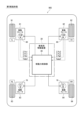
- FIG. 1 is a configuration diagram of a vehicle equipped with a vehicle braking device according to first to fourth embodiments
- FIG. 2 is a schematic configuration diagram of an electric brake for each wheel
- FIG. 3A is a schematic diagram of an electric brake pad
- FIG. 3B is a characteristic diagram of pad load and pad position
- FIG. 4 is a time chart of braking force command values, front wheel brakes and rear wheel brake three-phase currents according to a comparative example
- FIG. 5 is a time chart of the braking force command value, the three-phase current of the front wheel brake and the rear wheel brake by the up-down process of the first embodiment
- FIG. 1 is a configuration diagram of a vehicle equipped with a vehicle braking device according to first to fourth embodiments
- FIG. 2 is a schematic configuration diagram of an electric brake for each wheel
- FIG. 3A is a schematic diagram of an electric brake pad
- FIG. 3B is a characteristic diagram of pad load and pad position
- FIG. 4 is a time chart of braking force command values
- FIG. 6 is a time chart of the braking force command value, the three-phase current of the front wheel brake and the rear wheel brake by the up-down process of the second embodiment
- FIG. 7 is an overall flowchart of up-down processing
- FIG. 8 is a flow chart for judging the success or failure of the exclusion condition
- FIG. 9 is a diagram showing an example of start timing of up-down processing
- FIG. 10 is a flowchart of mode switching in the up-down process of the second embodiment
- FIG. 11 is a time chart of the braking force command value, the three-phase current of the front wheel brake and the rear wheel brake by the up-down process of Modification 1 of the second embodiment
- FIG. 12 is a time chart of the braking force command value and the three-phase current of the front wheel brake and the rear wheel brake in the up-down process of Modification 2 of the second embodiment
- FIG. 13 is a time chart of the braking force command value, the three-phase current of the front wheel brake and the rear wheel brake by the up-down process of the third embodiment
- FIG. 14 is a time chart of the braking force command value, the front wheel brake and the rear wheel brake three-phase current in the up-down process of the fourth embodiment
- FIG. 15 is a configuration diagram of a vehicle in which the vehicle braking device of the fifth embodiment is mounted
- FIG. 16 is a time chart of the braking force command value, the three-phase current of the front wheel brake, and the DC current of the rear wheel brake in the up-down process of the fifth embodiment.
- a vehicle braking device according to an embodiment of the present disclosure will be described based on the drawings.
- the vehicle braking device of this embodiment is mounted on a four-wheeled vehicle in which a plurality of electric brakes for generating braking force on the corresponding wheels are provided for each wheel.
- a vehicle braking device includes a braking force control section that controls the braking force generated by each electric brake.
- This embodiment The following first to fifth embodiments will be collectively referred to as "this embodiment".
- the configuration of the electric brake of the vehicle to which the first to fourth embodiments are applied is the same. Only the fifth embodiment differs in the configuration of the electric brake applied to the vehicle.
- a vehicle 901 is a four-wheeled vehicle having two pairs of left and right wheels 91, 92, 93, and 94 in the front-rear direction.
- the left and right wheels 91 and 92 in the front row are denoted as "FL, FR”
- the left and right wheels 93 and 94 in the rear row are denoted as "RL, RR”.
- a plurality of (four in this example) electric brakes 81, 82, 83, 84 are provided corresponding to the respective wheels 91, 92, 93, 94.
- the four consecutive reference numerals will be abbreviated as appropriate, such as “wheels 91-94” and “electric brakes 81-84”.
- the pair of electric brakes 81, 82 corresponding to the left and right wheels 91, 92 in the front row and the pair of electric brakes 83, 84 corresponding to the left and right wheels 93, 94 in the rear row A three-phase motor (“three-phase M” in the drawing) 60 as a “phase motor”.
- the electric brake is composed of a three-phase motor” strictly means that "the actuator of the electric brake is composed of a three-phase motor”.
- the three-phase motor 60 is a permanent magnet brushless motor.
- An electric brake configured with a polyphase motor is called a "polyphase electric brake”.
- the four electric brakes 81-84 are all three-phase electric brakes.
- the three-phase motors 60 corresponding to the electric brakes 81-84 have the same configuration and action, and are denoted by a single reference numeral "60". In the following specification, the three-phase motor 60 will be abbreviated simply as "motor 60".
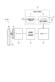
- the vehicle braking device 30 includes a braking force control section 40 .
- the braking force control unit 40 controls the braking forces generated by the electric brakes 81-84 on the corresponding wheels 91-94.
- the braking force control unit 40 controls the braking force generated by the electric brakes 81 to 84 by controlling the current applied to each motor 60 according to the braking force distribution of each wheel.
- the braking force control unit 40 calculates the integrated power value ( ⁇ Pu1, ⁇ Pv1, ⁇ Pw1)-( ⁇ Pu4, ⁇ Pv4, ⁇ Pw4) for each phase of the three-phase motor 60 corresponding to each of the electric brakes 81-84, or the motor temperature Temp1-Temp4.
- the integrated power values ⁇ Pu1, ⁇ Pv1, and ⁇ Pw1 for each phase are collectively described as “ ⁇ Puvw1”.
- "1-4" will be omitted and will be described as "integrated electric power value ⁇ Puvw" and "motor temperature Temp”.
- the motor temperature Temp is detected, for example, by a temperature sensor.
- the motor temperature Temp may be calculated by estimating a temperature rise from Joule heat due to energization of the three-phase motor 60 and adding it to the outside air temperature.
- the integrated power value ⁇ Puvw of the motor 60 and the motor temperature Temp have a positive correlation.
- the integrated power value ⁇ Puvw and the motor temperature Temp will be described later in the description of processing start, mode switching, and application exclusion. When not used as those conditions, the braking force control unit 40 does not need to acquire the integrated power value ⁇ Puvw or the motor temperature Temp.
- FIG. 2 shows a schematic configuration of the electric brakes 81-84 for each wheel.
- the braking force control unit 40 mainly includes an inverter 55 and a current command value calculation unit 51 as a configuration for controlling the drive of the three-phase motor 60 .
- Inverter 55 converts the DC power input from battery 15 and supplies AC power to each phase of three-phase motor 60 .
- a current command value calculation unit 51 calculates a current command value for the current supplied to the three-phase motor 60 according to the command torque trq * .
- the output torque of the motor 60 operates the pad 87 of the caliper 86 via the reduction gear/linear motion mechanism 85 .
- braking force is generated by friction. Also, the braking force is released when the pad 87 is separated from the disk 88 .
- the pads 87 of the electric brakes 81-81 shown in section IIIa of FIG. 2 will be supplemented with reference to FIGS. 3A and 3B.
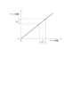
- the pad 87 has a spring-like characteristic, and the pushing force Fd by the direct acting mechanism 85 and the reaction force Fr corresponding to the amount of strain act in opposite directions.
- the amount of strain (that is, pad position) X and pad load F are approximately proportional. Therefore, if the pad position changes by ⁇ X due to the phase change of the motor 60, the pad load changes by ⁇ F.
- Patent Document 1 Japanese Patent No. 6505896
- the hysteresis characteristic between the motor torque and the braking force is used to maintain the braking force while reducing the current from the positive efficiency line to the inverse efficiency line. can be done.
- the lock energization is required while the rotation of the three-phase motor 60 is stopped.
- the current is prevented from concentrating on a specific phase of the three-phase motor 60 when the braking force is held. Focusing on FIG. 3B, if the target value of the pad load F is changed by changing the braking force command value, the pad position X will change, so that the energization phase of the motor 60, that is, the current of each phase can be changed. can. Conversely, it is also possible to calculate the fluctuation width of the braking force command value from the phase angle range desired to be changed.
- the braking force control unit 40 of the present embodiment sets the braking force command value is increased or decreased with respect to the reference value.
- a specific configuration of the up-down process will be described below for each embodiment.
- FIG. 4 shows braking force command values, front wheel brake and rear wheel brake three-phase currents in a comparative example in which up-down processing is not performed.
- the pair of electric brakes 81, 82 corresponding to the left and right wheels 91, 92 in the front row will be referred to as “front wheel brakes 81, 82”
- the pair of electric brakes 83, 84 corresponding to the left and right wheels 93, 94 in the rear row will be referred to as "rear brakes”.
- 83, 84 the front wheel braking force command value is indicated by "F”
- the rear wheel braking force command value is indicated by "R”.
- front wheels in the “front wheel braking force command value” refer to the left and right wheels 91 and 92 in the front row
- the “rear wheels” in the “rear wheel braking force command value” refer to the left and right wheels 93 and 94 in the rear row. That is, it means a pair of wheels rather than a single wheel.
- braking force on the vertical axis means a braking force command value.
- the total braking force command value increases from 0 to the total target value from time t0 to time t1, and is kept constant after time t1.
- both the front wheel braking force command value and the rear wheel braking force command value are half the total braking force command value. .
- This value is used as a reference value for each of the front wheel braking force command value and the rear wheel braking force command value.
- the dashed-dotted line indicating the front wheel braking force command value and the broken line indicating the rear wheel braking force command value cannot be identified if they overlap, so they are shown slightly shifted.
- the time charts of the following embodiments conform to the format of FIG. 4 and exemplify a case where the front wheel brakes 81, 82 and the rear wheel brakes 83, 84 have the same braking force distribution. However, a difference may be provided in the braking force distribution between the front wheel brakes 81 and 82 and the rear wheel brakes 83 and 84 . In that case, the reference value of the front wheel braking force command value and the reference value of the rear wheel braking force command value are illustrated by separate lines.
- the three-phase currents of the front wheel brakes 81, 82 and the rear wheel brakes 83, 84 become sinusoidal waves with gradually increasing amplitudes.
- the three-phase motor 60 is in a lock energized state, and the three-phase currents of the front wheel brakes 81 and 82 and the rear wheel brakes 83 and 84 have a constant value. If this state continues, the current will be concentrated in a specific phase and the heat generation will be uneven.
- the braking force control unit 40 successively superimposes sine waves having the same period on each of the reference values of the front wheel braking force command value and the rear wheel braking force command value with a half cycle shift.
- the sine wave value is positive
- the braking force command value increases with respect to the reference value
- the sine wave value is negative
- the braking force command value decreases with respect to the reference value. Therefore, the braking force command values for the front wheels and the rear wheels periodically increase or decrease with respect to each reference value.
- n1 to n5 correspond to the starting points (that is, nodes) of one cycle of the sine wave.
- the superposition of the sine wave is started with the time t1 at which the braking force command value reaches a certain value as the starting point n1.
- the timing to start superimposing the sine wave is not limited to this, and may be before or after time t1.
- the amplitude of the sine wave superimposed on the reference value of the front wheel braking force command value is equal to the amplitude of the sine wave superimposed on the reference value of the rear wheel braking force command value.
- the amplitude of the sine wave is set, for example, to approximately 10% of a reference value common to the front and rear wheels.
- the braking force command values for the front and rear wheels fluctuate within a range of approximately 90% to 110% of the reference value. If the reference values of the braking force command values for the front wheels and the rear wheels are different, for example, a predetermined ratio of the smaller reference value may be used as the sine wave amplitude common to the front and rear wheels.
- the three-phase currents of the front wheel brakes 81, 82 and the rear wheel brakes 83, 84 are expressed in the form of a sine wave composite function.
- the lock energization of the three-phase motor 60 is avoided by continuously changing the three-phase current. This prevents the current from concentrating on a specific phase and heat generation from being unbalanced.
- the braking force control unit 40 controls each reference value of the front wheel braking force command value and the rear wheel braking force command value by changing a rectangular shape in which a positive state exceeding the reference value and a negative state lower than the reference value alternate. Waves or trapezoidal waves are continuously superimposed. The amount of increase on the positive side and the amount of decrease on the negative side of the braking force command value are set symmetrically with respect to the reference value, for example, about 10% of the reference value.
- the front wheel braking force command value and the rear wheel braking force command value are periodically switched in terms of "predetermined fixed period".
- a positive or negative state of the front wheel braking force command value and the rear wheel braking force command value with respect to the reference value in a certain term is called a "mode”.
- the mode is "the front wheel braking force command value is positive and the rear wheel braking force command value is negative”. This is the mode in which the braking force command value is negative and the rear wheel braking force command value is positive.
- the front wheel braking force command value and the rear wheel braking force command value periodically increase or decrease with respect to each reference value.
- the "predetermined fixed period” is not limited to a period common to all modes, and a different fixed period may be predetermined for each mode. Further, different fixed periods may be determined in advance according to the time from the start of the up-down process or the number of mode switching times. Alternatively, instead of using the "predetermined fixed period", the mode switching may be executed using the current value of the parameter as a trigger, as will be described later with reference to FIG.
- a waveform that changes sharply in the change of the braking force command value at the time of mode switching is called a rectangular wave, and a waveform that changes gradually is called a trapezoidal wave.
- a rectangular wave can be interpreted as being included in a trapezoidal wave in a broad sense, but in this specification, it is described together with "a rectangular wave or a trapezoidal wave.” There is no essential difference in the action of up-down processing between square waves and trapezoid waves.
- the trapezoidal wave may include such a triangular wave, a sawtooth wave in which only one of the rising edge and the falling edge gradually changes, and the like.
- a waveform close to a rectangular wave is illustrated as a representative of the rectangular wave or the trapezoidal wave.
- FIG. 7 to 9 are common to the first and second embodiments.
- the flowchart of mode switching shown in FIG. 10 is intended for the second embodiment.
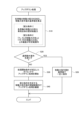
- the flowchart in FIG. 7 shows the entire up-down process.
- the symbol "S" means a step.
- the braking force control unit 40 determines braking force distribution for each wheel 91-94 based on the required braking force so as to satisfy the following distribution conditions.
- the braking force control unit 40 then calculates reference values for the front wheel braking force command value and the rear wheel braking force command value.
- Distribution condition 1 The sum of the braking forces generated by the wheels 91-94 is greater than or equal to the braking force required for the entire vehicle. This is an essential condition for braking the vehicle as desired.
- S20 it is determined whether the vehicle 901 satisfies the exemption requirements.
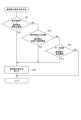
- An example of the success/failure determination of the exemption requirements will be described with reference to the flowchart of FIG. 8 .
- the success or failure of the three requirements is determined in order in S21 to S23. If YES is determined in at least one of S21 to S23, it is determined in S24 that the vehicle 901 satisfies the exemption requirements.
- S21 it is determined whether the required braking force is less than the non-application braking force threshold. In a region where the required braking force is small, heat generation does not pose a problem because the current that flows when the lock is energized is small.
- S22 it is determined whether or not the amount of variation in the required braking force is greater than the non-application braking force variation threshold. In the case of YES in S22, the motor 60 rotates to change the pad position, so the lock energization state does not occur in the first place.
- processing start timings include [1] to [4] shown in FIG.
- the braking force control unit 40 starts up-down processing at the same time as starting energization control of the electric brakes 81-84.
- the braking force control unit 40 starts the up-down process when the waiting time Twt elapses while the braking force command value exceeds the process start braking force threshold value (Br>Br_th_st).
- the process start braking force threshold is set to a value equal to or greater than the application exclusion braking force threshold. It is preferable to provide a standby time Twt in order to prevent erroneous determination due to the braking force temporarily exceeding the threshold value.
- the braking force control unit 40 determines that the braking force is maintained when the waiting time Twt elapses in which the amount of variation in the braking force command value is less than the process start braking force variation threshold value ( ⁇ Br ⁇ Br_th). , to start the up-down process.
- the process start braking force fluctuation threshold is set to a value equal to or less than the application exclusion braking force fluctuation threshold. It is preferable to provide a waiting time Twt in order to prevent erroneous determination due to temporary fluctuations in the braking force.
- the braking force control unit 40 operates when the integrated power value supplied to the three-phase motor 60 exceeds the integrated power threshold ( ⁇ P> ⁇ Pth), or when the temperature of the three-phase motor 60 exceeds the processing start temperature threshold.
- ⁇ P> ⁇ Pth the integrated power threshold
- the integrated power value ⁇ P is obtained by integrating power from the start of energization control.
- the integrated power values ⁇ Puvw for each phase may be calculated by adding the three phases, or the maximum value of the three-phase integrated power values ⁇ Puvw may be selected.
- the integrated power value ⁇ P is a value reflecting the motor temperature Temp.
- the processing start temperature threshold is set to a value equal to or higher than the application exclusion temperature threshold.
- the braking force control unit 40 determines the range of increase and decrease of the braking force command value that satisfies the above-described distribution conditions 1 and 2 regarding the distribution of the front wheel braking force command value and the rear wheel braking force command value. Continue up-down processing within.
- the braking force control unit 40 operates when the maximum value of the difference in the integrated power value supplied to each phase of the three-phase motor 60 exceeds the inter-phase integrated power difference threshold, or when the temperature difference between the phases of the three-phase motor 60 When the maximum value exceeds the interphase temperature difference threshold, the mode is switched.
- the braking force control unit 40 calculates the difference between the integrated power values of each phase using equations (1.1) to (1.3).
- the difference between the integrated power values of the phases is a value reflecting the temperature difference between the phases of the three-phase motor 60 .
- the braking force control unit 40 calculates the maximum value of the difference between the integrated power values of the phases using Equation (2).
- the maximum difference between the integrated power values of the phases is a value that reflects the maximum temperature difference between the phases of the three-phase motor 60 .
- S43 it is determined whether or not the maximum value MAX ⁇ P of the difference in integrated power value of each phase exceeds the inter-phase integrated power difference threshold ⁇ Pth (MAX ⁇ P> ⁇ Pth). In the case of YES in S43, the braking force control unit 40 executes mode switching in S44. If NO in S43, the routine returns to S41 and the routine is repeated.
- FIG. 6 In the up-down process of the second embodiment shown in FIG. 6, the amount of increase on the positive side and the amount of decrease on the negative side with respect to the reference value of the braking force command value are symmetrical. On the other hand, in the modified example, the amount of increase on the positive side and the amount of decrease on the negative side with respect to the reference value of the braking force command value are asymmetrical.
- the amount of increase/decrease in the front wheel braking force command value is set larger than the amount of increase/decrease in the rear wheel braking force command value on both the positive side and the negative side.
- the total braking force also increases or decreases as the front wheel braking force command value increases or decreases.
- the amount of decrease on the negative side of the braking force command value is set larger than the amount of increase on the positive side for both the front wheels and the rear wheels. The total braking force shifts to the negative side of the total target value.
- the braking force command values for the front and rear wheels may be changed asymmetrically with respect to the reference value. As a result, it is possible to determine whether to perform up-down processing for each of the front wheels and the rear wheels, thereby simplifying the control.
- FIGS. 13 and 14 are applications of the up-down processing of the second embodiment.
- An interval period is provided during which the command value is returned to the reference value and held.
- the rectangular wave or trapezoidal wave is continuously superimposed, whereas in the third and fourth embodiments, the rectangular wave or trapezoidal wave is intermittently superimposed with the interval period interposed.
- FIGS. 13 and 14 show examples in which the amount of increase on the positive side and the amount of decrease on the negative side of the braking force command value are set symmetrically with respect to the reference value. It may be set asymmetrically.
- one interval period is provided in three terms of mode switching. If the braking force change in the interval period is represented as "0", the front wheel braking force command value is "positive ⁇ negative ⁇ 0 ⁇ positive ⁇ negative” and the rear wheel braking force command value is "negative ⁇ positive” at times t1 to t6. ⁇ 0 ⁇ Negative ⁇ Positive”.
- the braking force command values for both the front wheels and the rear wheels in the interval period from time t3 to t4 are equal to the reference values.
- the total braking force command value is held constant through times t1 to t6.
- one interval period is provided in two terms of mode switching.
- the front wheel braking force command value changes "0 ⁇ negative ⁇ 0 ⁇ positive ⁇ 0”
- the rear wheel braking force command value changes "0 ⁇ positive ⁇ 0 ⁇ negative ⁇ 0”.
- the braking force command values for the front wheels and the rear wheels are equal to the reference values in each interval period of times t1 to t2, t3 to t4, and t5 to t6.
- the total braking force command value is held constant through times t1 to t6.
- FIG. 15 As shown in FIG. 15 , in a vehicle 905 on which the vehicle braking device 30 is mounted, a pair of electric brakes 81 and 82 corresponding to the left and right wheels 91 and 92 of the front row are composed of a three-phase motor 60 . On the other hand, a pair of electric brakes 83 , 84 corresponding to the left and right wheels 93 , 94 in the rear row are composed of DC motors (“DCM” in the figure) 70 .
- DCM DC motors
- the front wheel brakes 81 and 82 are three-phase electric brakes, but the rear wheel brakes 83 and 84 are not three-phase electric brakes.
- the idea of the fifth embodiment also includes a configuration in which the front wheel brakes 81 and 82 are configured by the DC motor 70 and the rear wheel brakes 83 and 84 are configured by the three-phase motor 60.
- FIG. 15 the idea of the fifth embodiment also includes a configuration in which the front wheel brakes 81 and 82 are configured by the DC motor 70 and the rear wheel brakes 83 and 84 are configured by the three-phase motor 60.
- FIG. 16 shows an example of up-down processing in the fifth embodiment according to the method according to the second embodiment.
- Changes in the braking force command value with respect to the reference value and changes in the three-phase currents of the front wheel brakes 81 and 82 are the same as in FIG.
- the DC current of the rear wheel brakes 83, 84 changes in proportion to the rear wheel braking force command value.
- the braking force control unit 40 controls the DC current of the DC motor 70 of the rear wheel brakes 83, 84 as a complementary process for keeping the total braking force of the vehicle 905 constant with the up-down process of the front wheel brakes 81, 82. to adjust. Since there is no point in avoiding current concentration in a specific phase in the DC motor 70, the rear wheel brakes 83 and 84 are not directly subject to the up/down process.
- the waveform superimposed on the braking force command value in the up-down process is not limited to a sine wave, rectangular wave, or trapezoidal wave, and may be other waveforms.
- the number of phases of the multiphase motor that constitutes the electric brake is not limited to three, and may be four or more.
- the braking force control unit and techniques described in this disclosure can be implemented by a dedicated computer provided by configuring a processor and memory programmed to perform one or more functions embodied by a computer program. , may be implemented. Alternatively, the braking force control and techniques described in this disclosure may be implemented by a dedicated computer provided by configuring the processor with one or more dedicated hardware logic circuits. Alternatively, the braking force control unit and techniques described in this disclosure may be implemented by a processor and memory programmed to perform one or more functions and a processor configured by one or more hardware logic circuits. It may also be implemented by one or more dedicated computers configured in combination. The computer program may also be stored as computer-executable instructions on a computer-readable non-transitional tangible recording medium.
Landscapes
- Engineering & Computer Science (AREA)
- Transportation (AREA)
- Mechanical Engineering (AREA)
- Microelectronics & Electronic Packaging (AREA)
- Physics & Mathematics (AREA)
- Fluid Mechanics (AREA)
- Power Engineering (AREA)
- Regulating Braking Force (AREA)
- Braking Systems And Boosters (AREA)
- Control Of Electric Motors In General (AREA)
Abstract
車両用制動装置(30)は、対応する車輪に制動力を発生させる複数の電動ブレーキ(81-84)が各車輪(91-94)に設けられた四輪車両(901、905)に搭載される。車両用制動装置(30)は、各電動ブレーキ(81-84)が発生させる制動力を制御する制動力制御部(40)を備える。複数の電動ブレーキのうち、前列左右輪(91、92)に対応する一対の電動ブレーキ(81、82)、又は、後列左右輪(93、94)に対応する一対の電動ブレーキ(83、84)のうち少なくとも一方は、三相以上の多相モータ(60)で構成された多相電動ブレーキである。制動力制御部(40)は、制動力が保持されている時に多相モータ(60)の特定相に電流が集中しないように、多相電動ブレーキへの制動力指令値を基準値に対して増減させる「アップダウン処理」を実行する。
Description
本出願は、2021年12月8日に出願された日本出願番号2021-199179号に基づくものであり、ここにその記載内容を援用する。
本開示は、車両用制動装置に関する。
従来、モータ通電により制動力を発生させる車両用制動装置が知られている。例えば特許文献1に開示された電動ブレーキ装置は、モータ通電により発生するモータトルクを摩擦パッドの押圧力による制動力に変換する。モータトルクと制動力との関係は、各部での摩擦力のため、制動力が増加するときの正効率線と、制動力が減少するときの逆効率線とで異なり、正効率線から逆効率線に推移する間はモータトルクが変化しても制動力が保持されるというヒステリシス特性を有している。
特許文献1の従来技術によると、正効率線により目標制動力よりも少し高い制動力を発生させてから制動力を保持しつつ電流を下げ、逆効率線で動作させて目標制動力まで下げるように制御することで、電流を低減することができる。しかし、制動力を保持する過程でロック通電が必要であり、電動ブレーキのアクチュエータが多相モータで構成されている場合、特定の相に電流が集中して発熱が偏るという問題がある。
本開示の目的は、多相モータで構成された電動ブレーキの制動力保持によるロック通電時に特定の相に発熱が偏ることを防止する車両用制動装置を提供することにある。
本開示の車両用制動装置は、対応する車輪に制動力を発生させる複数の電動ブレーキが各車輪に設けられた四輪車両に搭載される。車両用制動装置は、各電動ブレーキが発生させる制動力を制御する制動力制御部を備える。
複数の電動ブレーキのうち、前列左右輪に対応する一対の電動ブレーキ、又は、後列左右輪に対応する一対の電動ブレーキのうち少なくとも一方は、三相以上の多相モータで構成された多相電動ブレーキである。
車両が所定の適用除外要件を満たす場合を除き、制動力制御部は、制動力が保持されている時に多相モータの特定相に電流が集中しないように、多相電動ブレーキへの制動力指令値を基準値に対して増減させる「アップダウン処理」を実行する。
例えば制動力制御部は、アップダウン処理において、多相電動ブレーキについての制動力指令値の基準値に正弦波を重畳させる。或いは、制動力制御部は、制動力指令値の基準値に対し、基準値を上回る正状態と基準値を下回る負状態と交替する矩形波又は台形波を連続的又は断続的に重畳させる。
これにより本開示では、多相モータで構成された電動ブレーキの制動力保持によるロック通電時に特定の相に発熱が偏ることを防止することができる。
本開示についての上記目的及びその他の目的、特徴や利点は、添付の図面を参照しながら下記の詳細な記述により、より明確になる。その図面は、
図1は、第1~第4実施形態の車両用制動装置が搭載される車両の構成図であり、
図2は、各車輪の電動ブレーキの模式的な構成図であり、
図3Aは、電動ブレーキのパッドの模式図であり、
図3Bは、パッド荷重とパッド位置との特性図であり、
図4は、比較例による制動力指令値、前輪ブレーキ及び後輪ブレーキ三相電流のタイムチャートであり、
図5は、第1実施形態のアップダウン処理による制動力指令値、前輪ブレーキ及び後輪ブレーキの三相電流のタイムチャートであり、
図6は、第2実施形態のアップダウン処理による制動力指令値、前輪ブレーキ及び後輪ブレーキの三相電流のタイムチャートであり、
図7は、アップダウン処理の全体フローチャートであり、
図8は、適用除外条件成否判定のフローチャートであり、
図9は、アップダウン処理の開始タイミングの例を示す図であり、
図10は、第2実施形態のアップダウン処理でのモード切替のフローチャートであり、
図11は、第2実施形態変形例1のアップダウン処理による制動力指令値、前輪ブレーキ及び後輪ブレーキの三相電流のタイムチャートであり、
図12は、第2実施形態変形例2のアップダウン処理による制動力指令値、前輪ブレーキ及び後輪ブレーキの三相電流のタイムチャートであり、
図13は、第3実施形態のアップダウン処理による制動力指令値、前輪ブレーキ及び後輪ブレーキの三相電流のタイムチャートであり、
図14は、第4実施形態のアップダウン処理による制動力指令値、前輪ブレーキ及び後輪ブレーキの三相電流のタイムチャートであり、
図15は、第5実施形態の車両用制動装置が搭載される車両の構成図であり、
図16は、第5実施形態のアップダウン処理による制動力指令値、前輪ブレーキの三相電流及び後輪ブレーキの直流電流のタイムチャートである。
本開示の実施形態による車両用制動装置を図面に基づいて説明する。本実施形態の車両用制動装置は、対応する車輪に制動力を発生させる複数の電動ブレーキが各車輪に設けられた四輪車両に搭載される。車両用制動装置は、各電動ブレーキが発生させる制動力を制御する制動力制御部を備える。以下の第1~第5実施形態を包括して「本実施形態」という。本実施形態のうち、第1~第4実施形態が適用される車両の電動ブレーキの構成は同じである。第5実施形態のみ、適用される車両の電動ブレーキの構成が異なる。
[第1~第4実施形態が適用される車両の電動ブレーキの構成]
最初に図1~図3を参照し、第1~第4実施形態の車両用制動装置30が搭載される車両901及び電動ブレーキ81-84の構成を説明する。図1に示すように、車両901は、前後方向において二列の左右対の車輪91、92、93、94を有する四輪車両である。前列左右輪91、92に「FL、FR」、後列左右輪93、94に「RL、RR」と記す。
最初に図1~図3を参照し、第1~第4実施形態の車両用制動装置30が搭載される車両901及び電動ブレーキ81-84の構成を説明する。図1に示すように、車両901は、前後方向において二列の左右対の車輪91、92、93、94を有する四輪車両である。前列左右輪91、92に「FL、FR」、後列左右輪93、94に「RL、RR」と記す。
各車輪91、92、93、94に対応して複数(この例では四つ)の電動ブレーキ81、82、83、84が設けられている。以下、連続する四つの符号を適宜、「車輪91-94」、「電動ブレーキ81-84」のように省略して記す。後述の記号「積算電力値ΣP1-ΣP4」、「温度Temp1-Temp4」についても同様とする。
第1~第4実施形態では、前列左右輪91、92に対応する一対の電動ブレーキ81、82、及び、後列左右輪93、94に対応する一対の電動ブレーキ83、84は、いずれも「多相モータ」としての三相モータ(図中「三相M」)60で構成されている。なお、「電動ブレーキが三相モータで構成されている」とは、厳密には「電動ブレーキのアクチュエータが三相モータで構成されている」ことを意味する。具体的に三相モータ60は、永久磁石式のブラシレスモータである。
多相モータで構成された電動ブレーキを「多相電動ブレーキ」という。第1~第4実施形態では、四つの電動ブレーキ81-84は、いずれも三相電動ブレーキである。また、各電動ブレーキ81-84に対応する三相モータ60の構成、作用は同様であるものとし、単一の符号「60」を用いる。以下の明細書中、適宜、三相モータ60を単に「モータ60」と省略する。
車両用制動装置30は、制動力制御部40を備える。制動力制御部40は、各電動ブレーキ81-84が対応する車輪91-94に発生させる制動力を制御する。制動力制御部40は、各車輪の制動力配分に応じて各モータ60に通電する電流を制御することで、電動ブレーキ81-84が発生する制動力を制御する。
制動力制御部40は、各電動ブレーキ81-84に対応する三相モータ60の相毎の積算電力値(ΣPu1、ΣPv1、ΣPw1)-(ΣPu4、ΣPv4、ΣPw4)、又は、モータ温度Temp1-Temp4の少なくとも一方を取得してもよい。以下、相毎の積算電力値ΣPu1、ΣPv1、ΣPw1を「ΣPuvw1」のようにまとめて記載する。また、各電動ブレーキ81-84について包括する説明では「1-4」を省略し、「積算電力値ΣPuvw」、「モータ温度Temp」のように記す。
モータ温度Tempは、例えば温度センサにより検出される。或いは、三相モータ60への通電によるジュール熱から温度上昇を推定し、外気温に加算することでモータ温度Tempを算出してもよい。モータ60の積算電力値ΣPuvwとモータ温度Tempとは正の相関を有する。積算電力値ΣPuvw及びモータ温度Tempは、処理開始、モード切替、及び、適用除外の説明で後述される。それらの条件として使用しない場合、制動力制御部40は、積算電力値ΣPuvw又はモータ温度Tempを取得しなくてもよい。
図2に、各車輪の電動ブレーキ81-84の概略構成を示す。制動力制御部40は三相モータ60の駆動制御の構成として、主にインバータ55及び電流指令値演算部51を含む。インバータ55は、バッテリ15から入力された直流電力を変換し、三相モータ60の各相に交流電力を供給する。電流指令値演算部51は、三相モータ60に通電される電流について、指令トルクtrq*に応じて電流指令値を演算する。
モータ60の出力トルクは、減速機・直動機構85を介してキャリパ86のパッド87を動作させる。パッド87が移動して各車輪91-94のディスク88に押し付けられることで、摩擦により制動力が発生する。また、パッド87がディスク88から離れることで、制動力が解除される。
図3A、図3Bを参照し、図2のIIIa部に示す電動ブレーキ81-81のパッド87の特性について補足する。図3Aに示すように、パッド87はバネのような特性を持ち、直動機構85による押し込み力Fdと、ひずみ量に応じた反力Frとが互いに反対方向に作用する。図3Bに示すように、ひずみ量(すなわちパッド位置)Xとパッド荷重Fとはほぼ比例する。したがって、モータ60の位相変化によりパッド位置がΔX変化すれば、パッド荷重はΔF変化する。
ところで、特許文献1(特許第6505896号公報)の従来技術によると、モータトルクと制動力とのヒステリシス特性を利用し、正効率線から逆効率線まで電流を低減しながら制動力を保持することができる。しかし、制動力を保持する過程で、三相モータ60の回転が停止した状態でのロック通電が必要であり、特定の相に電流が集中して発熱が偏るという問題がある。
そこで本実施形態では、制動力が保持されている時に三相モータ60の特定相に電流が集中しないようにすることを図る。図3Bに着目すると、制動力指令値を変化させてパッド荷重Fの狙い値を変動させれば、パッド位置Xが変動するため、モータ60の通電位相、すなわち各相の電流を変動させることができる。逆に変化させたい位相角度範囲から制動力指令値の変動幅を算出することもできる。
この着眼点に基づき、本実施形態の制動力制御部40は、制動力が保持されている時に三相モータ60の特定相に電流が集中しないように、三相電動ブレーキへの制動力指令値を基準値に対して増減させる「アップダウン処理」を実行する。以下、アップダウン処理の具体的な構成について実施形態毎に説明する。
各実施形態の説明に先立ち、図4に、アップダウン処理を実施しない比較例での、制動力指令値、前輪ブレーキ及び後輪ブレーキ三相電流を示す。以下、前列左右輪91、92に対応する一対の電動ブレーキ81、82を「前輪ブレーキ81、82」といい、後列左右輪93、94に対応する一対の電動ブレーキ83、84を「後輪ブレーキ83、84」という。図中、前輪制動力指令値を「F」、後輪制動力指令値を「R」と記す。「前輪制動力指令値」の「前輪」は前列左右輪91、92、「後輪制動力指令値」の「後輪」は後列左右輪93、94を意味する。すなわち、一つの車輪でなく一対の車輪対を意味する。また、縦軸の「制動力」は制動力指令値を意味する。
合計の制動力指令値は、時刻t0から時刻t1にかけて0から合計目標値まで増加し、時刻t1以後、一定に保持される。前輪ブレーキ81、82と後輪ブレーキ83、84との制動力配分が同等の場合、前輪制動力指令値と後輪制動力指令値とは、いずれも合計制動力指令値の半分の値となる。この値を、前輪制動力指令値、後輪制動力指令値それぞれの基準値とする。図示の都合上、前輪制動力指令値を示す一点鎖線と、後輪制動力指令値を示す破線とが重なると識別できないため、わずかにずらして記載されている。
以下の各実施形態のタイムチャートは、図4の書式に準じ、前輪ブレーキ81、82と後輪ブレーキ83、84との制動力配分が同等の場合を例示する。ただし、前輪ブレーキ81、82と後輪ブレーキ83、84との制動力配分に差を設けてもよい。その場合、前輪制動力指令値の基準値と後輪制動力指令値の基準値とは別々の線で図示される。
時刻t0~t1の制動力上昇中、前輪ブレーキ81、82及び後輪ブレーキ83、84の三相電流は、振幅が漸増する正弦波となる。時刻t1以後、三相モータ60はロック通電状態となり、前輪ブレーキ81、82及び後輪ブレーキ83、84の三相電流は一定の値となる。この状態が継続すると、特定の相に電流が集中し、発熱が偏ることになる。
(第1実施形態)
図5を参照し、第1実施形態のアップダウン処理について説明する。第1実施形態では、制動力制御部40は、前輪制動力指令値及び後輪制動力指令値の各基準値に対し、互いに同周期の正弦波を半周期ずらして連続的に重畳させる。正弦波の値が正のとき制動力指令値は基準値に対して増加し、正弦波の値が負のとき制動力指令値は基準値に対して減少する。したがって、前輪及び後輪の制動力指令値は各基準値に対して周期的に増減する。
図5を参照し、第1実施形態のアップダウン処理について説明する。第1実施形態では、制動力制御部40は、前輪制動力指令値及び後輪制動力指令値の各基準値に対し、互いに同周期の正弦波を半周期ずらして連続的に重畳させる。正弦波の値が正のとき制動力指令値は基準値に対して増加し、正弦波の値が負のとき制動力指令値は基準値に対して減少する。したがって、前輪及び後輪の制動力指令値は各基準値に対して周期的に増減する。
横軸には、正弦波の一周期の起点(すなわち節)に対応する時刻をn1~n5と記す。例えば、制動力指令値が一定値に達した時刻t1を起点n1として正弦波の重畳が開始される。なお、図9を参照して後述するように、正弦波の重畳を開始するタイミングはこれに限らず、時刻t1より前でも後でもよい。
好ましくは、前輪制動力指令値の基準値に重畳される正弦波の振幅と、後輪制動力指令値の基準値に重畳される正弦波の振幅とは等しい。これにより、前輪制動力指令値と後輪制動力指令値との合計が一定に保持され、制動力の配分が周期的に変更される。正弦波の振幅は、例えば前輪及び後輪に共通の基準値の約10%に設定される。この場合、前輪及び後輪の制動力指令値は基準値の約90%~110%の範囲で変動する。また、前輪及び後輪の制動力指令値の基準値が異なる場合、例えば小さい方の基準値の所定比率の値を前輪及び後輪に共通の正弦波振幅としてもよい。
前輪ブレーキ81、82及び後輪ブレーキ83、84の三相電流は、正弦波の合成関数の形で表される。第1実施形態では三相電流が連続的に変化することで、三相モータ60のロック通電が回避される。これにより、特定相に電流が集中し発熱が偏ることが防止される。
(第2実施形態)
図6を参照し、第2実施形態のアップダウン処理について説明する。第2実施形態では、制動力制御部40は、前輪制動力指令値及び後輪制動力指令値の各基準値に対し、基準値を上回る正状態と基準値を下回る負状態とが交替する矩形波又は台形波を連続的に重畳させる。制動力指令値の正側の増加量及び負側の減少量は、基準値に対して対称に、例えば基準値の約10%に設定される。
図6を参照し、第2実施形態のアップダウン処理について説明する。第2実施形態では、制動力制御部40は、前輪制動力指令値及び後輪制動力指令値の各基準値に対し、基準値を上回る正状態と基準値を下回る負状態とが交替する矩形波又は台形波を連続的に重畳させる。制動力指令値の正側の増加量及び負側の減少量は、基準値に対して対称に、例えば基準値の約10%に設定される。
図6に示す例では、時刻t1以後、「予め定められた固定周期」のタームで、前輪制動力指令値及び後輪制動力指令値が周期的に切り替えられる。あるタームでの、前輪制動力指令値及び後輪制動力指令値の基準値に対する正又は負の状態を「モード」という。時刻t1~t2、時刻t3~t4、時刻t5~t6では「前輪制動力指令値が正で後輪制動力指令値が負」のモードであり、時刻t2~t3、時刻t4~t5では「前輪制動力指令値が負で後輪制動力指令値が正」のモードである。
このように、前輪制動力指令値及び後輪制動力指令値は各基準値に対して周期的に増減する。ここで「予め定められた固定周期」は、全てのモードに共通の周期に限らず、モード毎に異なる固定周期が予め定められてもよい。また、アップダウン処理開始からの時間やモード切替回数に応じて異なる固定周期が予め定められてもよい。或いは「予め定められた固定周期」を用いるのでなく、図10を参照して後述するように、パラメータの現在値をトリガとしてモード切替が実行されるようにしてもよい。
モード切替時の制動力指令値の変化において急峻に変化する波形を矩形波といい、徐変する波形を台形波という。矩形波は広義の台形波に含まれると解釈することも可能であるが、本明細書では「矩形波又は台形波」と並べて記載する。矩形波と台形波とではアップダウン処理の作用における本質的な違いはない。
さらに、台形波の徐変時間がモード切替周期の半分近くになると見かけ上は三角波に近づく。このような三角波や、立上がり又は立下りの一方のみが徐変する鋸波等を台形波に含むものとしてもよい。図6以下のタイムチャートでは、矩形波又は台形波を代表して、矩形波に近い波形を図示する。
第2実施形態では、モードの切替毎に三相電流がステップ的に変化することで三相モータ60のロック通電が回避される。これにより、第1実施形態と同様に、特定相に電流が集中し発熱が偏ることが防止される。また、特に矩形波の場合、同一ターム中は一定の制動力指令値が出力されるため、制動力制御部40の演算負荷が低減される。第2実施形態の変形例、及び、第2実施形態を応用した第3、第4実施形態については、アップダウン処理のアルゴリズムの後で説明する。
(アップダウン処理のアルゴリズム)
次に図7~図10を参照し、アップダウン処理のアルゴリズムについて説明する。図7~図9は第1、第2実施形態に共通する。図10に示すモード切替のフローチャートは、第2実施形態を対象とする。
次に図7~図10を参照し、アップダウン処理のアルゴリズムについて説明する。図7~図9は第1、第2実施形態に共通する。図10に示すモード切替のフローチャートは、第2実施形態を対象とする。
図7のフローチャートにアップダウン処理の全体を示す。以下のフローチャートの説明で記号「S」はステップを意味する。S10で制動力制御部40は、要求制動力に基づき、下記の配分条件を満たすように各車輪91-94の制動力配分を決定する。そして制動力制御部40は、前輪制動力指令値及び後輪制動力指令値の基準値を算出する。
[配分条件1]:各車輪91-94で発生する制動力の和が車両全体の要求制動力以上となる。これは、要求通りに車両を制動させるために必須の条件である。
[配分条件2]:前後列の左輪91、93(FL、RL)の制動力の和と前後列の右輪92、94(FR、RR)の制動力の和との偏差が所定の範囲内となる。左右輪の制動力の偏差を上限値以下とすることで、例えば直進制動時にヨーモーメントが発生することによる車両偏向を抑制することができる。ただし、制動力の偏差が0であることが常に最適とは限らない。意図的に左右輪の制動力に差を設けたい場合、制動力の偏差が下限値以上上限値以下となるように条件を設定してもよい。
S20では、車両901が適用除外要件を満たすか判断される。図8のフローチャートを参照し、適用除外要件の成否判定の例について説明する。この例では3項目の要件についてS21~S23で順に成否を判断する。S21~S23のうち少なくとも一つでYESと判断されると、S24で車両901が適用除外要件を満たすと判定される。
S21では、要求制動力が適用除外制動力閾値未満であるか判断される。要求制動力が小さい領域ではロック通電時に流れる電流が小さいため、発熱は問題とならない。S22では、要求制動力の変動量が適用除外制動力変動閾値より大きいか判断される。S22でYESの場合、モータ60が回転してパッド位置を変化させるため、そもそもロック通電状態にならない。
S23では、三相モータ60のモータ温度Tempが適用除外温度閾値未満であるか判断される。たとえロック通電が行われても、許容上限温度に対して十分に余裕がある状況では、アップダウン処理を行う必要はない。
このように、そもそもロック通電にならない場合や、ロック通電しても特定の相の発熱が問題とならない場合、S24で車両901が適用除外要件を満たすと判定される。その結果、図7のS20でYESと判断される。するとS26で制動力制御部40は、アップダウン処理を実行せず、制動力指令値を基準値で一定に保持する。
S20でNOと判断された場合、すなわち、車両が適用除外要件を満たす場合を除き、S30で制動力制御部40は、処理開始条件が成立したタイミングでアップダウン処理を開始する。処理開始タイミングの例として、図9に示す[1]~[4]が挙げられる。
[1]制動力制御部40は、電動ブレーキ81-84の通電制御を開始すると同時にアップダウン処理を開始する。
[2]制動力制御部40は、制動力指令値が処理開始制動力閾値を超えた状態(Br>Br_th_st)が待機時間Twt経過したとき、アップダウン処理を開始する。処理開始制動力閾値は適用除外制動力閾値以上の値に設定される。一時的に制動力が閾値を超えることによる誤判定を防止するため待機時間Twtを設けることが好ましい。
[3]制動力制御部40は、制動力指令値の変動量が処理開始制動力変動閾値未満である状態(ΔBr<ΔBr_th)が待機時間Twt経過したとき、制動力保持状態であると判断し、アップダウン処理を開始する。処理開始制動力変動閾値は適用除外制動力変動閾値以下の値に設定される。一時的に制動力が変動することによる誤判定を防止するため待機時間Twtを設けることが好ましい。
[4]制動力制御部40は、三相モータ60に供給される積算電力値が積算電力閾値を上回った(ΣP>ΣPth)とき、又は、三相モータ60の温度が処理開始温度閾値を上回った(Temp>Temp_th_st)とき、アップダウン処理を開始する。積算電力値ΣPは、通電制御開始からの電力が積算される。例えば相毎の積算電力値ΣPuvwを三相加算して算出してもよく、三相の積算電力値ΣPuvwのうちの最大値が選択されてもよい。積算電力値ΣPはモータ温度Tempが反映された値となる。処理開始温度閾値は適用除外温度閾値以上の値に設定される。
アップダウン処理の開始後、S40で制動力制御部40は、前輪制動力指令値と後輪制動力指令値との配分に関し、上述の配分条件1、2を充足する制動力指令値の増減範囲内でアップダウン処理を継続する。
図10を参照し、第2実施形態においてパラメータの現在値をトリガとしてモード切替を行う処理の例について説明する。制動力制御部40は、三相モータ60の各相に供給される積算電力値の差の最大値が相間積算電力差閾値を上回ったとき、又は、三相モータ60の各相の温度差の最大値が相間温度差閾値を上回ったとき、モードを切り替える。
S41で制動力制御部40は、各相の積算電力値の差を式(1.1)~(1.3)により演算する。各相の積算電力値の差は、三相モータ60の各相の温度差が反映された値となる。
ΔΣPu-v=|ΔΣPu-ΔΣPv| ・・・(1.1)
ΔΣPv-w=|ΔΣPv-ΔΣPw| ・・・(1.2)
ΔΣPw-u=|ΔΣPw-ΔΣPu| ・・・(1.3)
ΔΣPv-w=|ΔΣPv-ΔΣPw| ・・・(1.2)
ΔΣPw-u=|ΔΣPw-ΔΣPu| ・・・(1.3)
S42で制動力制御部40は、各相の積算電力値の差の最大値を式(2)により演算する。各相の積算電力値の差の最大値は、三相モータ60の各相の温度差の最大値が反映された値となる。
MAXΔΣP=MAX(ΔΣPu-v、ΔΣPv-w、ΔΣPw-u)
・・・(2)
・・・(2)
S43では、各相の積算電力値の差の最大値MAXΔΣPが相間積算電力差閾値ΔΣPthを上回っている(MAXΔΣP>ΔΣPth)か判断される。S43でYESの場合、S44で制動力制御部40はモード切替を実行する。S43でNOの場合、S41に戻ってルーチンが繰り返される。
(第2実施形態の変形例)
次に図11、図12を参照し、第2実施形態の変形例について説明する。図6に示す第2実施形態のアップダウン処理では、制動力指令値の基準値に対する正側の増加量と負側の減少量とが対称である。これに対して変形例では、制動力指令値の基準値に対する正側の増加量と負側の減少量とが非対称である。
次に図11、図12を参照し、第2実施形態の変形例について説明する。図6に示す第2実施形態のアップダウン処理では、制動力指令値の基準値に対する正側の増加量と負側の減少量とが対称である。これに対して変形例では、制動力指令値の基準値に対する正側の増加量と負側の減少量とが非対称である。
図11に示す変形例1では、前輪制動力指令値の増減量が正側、負側とも後輪制動力指令値の増減量よりも大きく設定されている。前輪制動力指令値の増減に伴って合計制動力も増減する。図12に示す変形例2では、前輪、後輪とも制動力指令値の負側の減少量が正側の増加量よりも大きく設定されている。合計制動力は合計目標値よりも負側にシフトする。
合計制動力の変化による車両挙動への影響が許容範囲内であれば、このように前輪及び後輪の制動力指令値を基準値に対して非対称に変化させてもよい。これにより、前輪、後輪毎にアップダウン処理の実施判断が可能となり、制御が簡単になる。
(第3、第4実施形態)
図13、図14に示す第3、第4実施形態は、第2実施形態のアップダウン処理を応用したものであり、制動力指令値を基準値に対して増減させる期間の途中に、制動力指令値を基準値に戻して保持するインターバル期間が設けられている。インターバル期間の無い第2実施形態では矩形波又は台形波が連続的に重畳されるのに対し、第3、第4実施形態ではインターバル期間を挟んで矩形波又は台形波が断続的に重畳される。図13、図14には、制動力指令値の正側の増加量及び負側の減少量が基準値に対して対称に設定された例を示すが、第2実施形態の変形例のように非対称に設定されてもよい。
図13、図14に示す第3、第4実施形態は、第2実施形態のアップダウン処理を応用したものであり、制動力指令値を基準値に対して増減させる期間の途中に、制動力指令値を基準値に戻して保持するインターバル期間が設けられている。インターバル期間の無い第2実施形態では矩形波又は台形波が連続的に重畳されるのに対し、第3、第4実施形態ではインターバル期間を挟んで矩形波又は台形波が断続的に重畳される。図13、図14には、制動力指令値の正側の増加量及び負側の減少量が基準値に対して対称に設定された例を示すが、第2実施形態の変形例のように非対称に設定されてもよい。
図13に示す第3実施形態では、モード切替の3タームに1回のインターバル期間が設けられている。インターバル期間での制動力変化を「0」と表すと、時刻t1~t6において、前輪制動力指令値は「正→負→0→正→負」、後輪制動力指令値は「負→正→0→負→正」と変化する。時刻t3~t4のインターバル期間での制動力指令値は前輪、後輪とも基準値に等しい。時刻t1~t6を通じて合計の制動力指令値は一定に保持される。
図14に示す第4実施形態では、モード切替の2タームに1回のインターバル期間が設けられている。時刻t1~t6において、前輪制動力指令値は「0→負→0→正→0」、後輪制動力指令値は「0→正→0→負→0」と変化する。なお、時刻t2~t3のタームの増減量と、時刻t4~t5のタームの増減量とは異なっている。時刻t1~t2、t3~t4、t5~t6の各インターバル期間での制動力指令値は前輪、後輪とも基準値に等しい。時刻t1~t6を通じて合計の制動力指令値は一定に保持される。
(第5実施形態)
次に図15、図16を参照し、第5実施形態について説明する。図15に示すように、車両用制動装置30が搭載される車両905において、前列左右輪91、92に対応する一対の電動ブレーキ81、82は三相モータ60で構成されている。一方、後列左右輪93、94に対応する一対の電動ブレーキ83、84は直流モータ(図中「DCM」)70で構成されている。
次に図15、図16を参照し、第5実施形態について説明する。図15に示すように、車両用制動装置30が搭載される車両905において、前列左右輪91、92に対応する一対の電動ブレーキ81、82は三相モータ60で構成されている。一方、後列左右輪93、94に対応する一対の電動ブレーキ83、84は直流モータ(図中「DCM」)70で構成されている。
この例では前輪ブレーキ81、82は三相電動ブレーキであるが、後輪ブレーキ83、84は三相電動ブレーキではない。図15とは逆に、前輪ブレーキ81、82が直流モータ70で構成され、後輪ブレーキ83、84が三相モータ60で構成された構成も第5実施形態の思想に含まれる。
図16に、第5実施形態での、第2実施形態に準じた方式でのアップダウン処理の例を示す。制動力指令値の基準値に対する変化、及び、前輪ブレーキ81、82の三相電流の変化は図6と同じである。後輪ブレーキ83、84の直流電流は後輪制動力指令値に比例して変化する。
制動力制御部40は、前輪ブレーキ81、82のアップダウン処理に伴って車両905の合計制動力を一定に保持するための補完的処理として、後輪ブレーキ83、84の直流モータ70の直流電流を調整する。直流モータ70では特定相への電流集中を回避する意味合いはないため、後輪ブレーキ83、84はアップダウン処理の直接の対象には含まれない。
(その他の実施形態)
(a)上述の実施形態では、アップダウン処理により前輪ブレーキ81、82と後輪ブレーキ83、84との間での制動力指令値の配分が変動する。それに加え、前列左輪ブレーキ81と前列右輪ブレーキ82との間、又は、後列左輪ブレーキ83と後列右輪ブレーキ84との間での制動力指令値の配分が変動するようにしてもよい。
(a)上述の実施形態では、アップダウン処理により前輪ブレーキ81、82と後輪ブレーキ83、84との間での制動力指令値の配分が変動する。それに加え、前列左輪ブレーキ81と前列右輪ブレーキ82との間、又は、後列左輪ブレーキ83と後列右輪ブレーキ84との間での制動力指令値の配分が変動するようにしてもよい。
(b)アップダウン処理において制動力指令値に重畳される波形は、正弦波、矩形波又は台形波に限らず、その他の波形でもよい。
(c)電動ブレーキを構成する多相モータの相の数は三相に限らず、四相以上であってもよい。
以上、本開示はこのような実施形態に限定されるものではなく、その趣旨を逸脱しない範囲において、種々の形態で実施することができる。
本開示に記載の制動力制御部及びその手法は、コンピュータプログラムにより具体化された一つ乃至は複数の機能を実行するようにプログラムされたプロセッサ及びメモリを構成することによって提供された専用コンピュータにより、実現されてもよい。あるいは、本開示に記載の制動力制御部及びその手法は、一つ以上の専用ハードウェア論理回路によってプロセッサを構成することによって提供された専用コンピュータにより、実現されてもよい。もしくは、本開示に記載の制動力制御部及びその手法は、一つ乃至は複数の機能を実行するようにプログラムされたプロセッサ及びメモリと一つ以上のハードウェア論理回路によって構成されたプロセッサとの組み合わせにより構成された一つ以上の専用コンピュータにより、実現されてもよい。また、コンピュータプログラムは、コンピュータにより実行されるインストラクションとして、コンピュータ読み取り可能な非遷移有形記録媒体に記憶されていてもよい。
本開示は実施形態に準拠して記述された。しかしながら、本開示は当該実施形態および構造に限定されるものではない。本開示は、様々な変形例および均等の範囲内の変形をも包含する。また、様々な組み合わせおよび形態、さらには、それらに一要素のみ、それ以上、あるいはそれ以下、を含む他の組み合わせおよび形態も本開示の範疇および思想範囲に入るものである。
Claims (12)
- 対応する車輪に制動力を発生させる複数の電動ブレーキ(81-84)が各車輪に設けられた四輪車両(901、905)に搭載される車両用制動装置であって、
各前記電動ブレーキが発生させる制動力を制御する制動力制御部(40)を備え、
複数の前記電動ブレーキのうち、前列左右輪(91、92)に対応する一対の前記電動ブレーキ(81、82)、又は、後列左右輪(93、94)に対応する一対の前記電動ブレーキ(83、84)のうち少なくとも一方は、三相以上の多相モータ(60)で構成された多相電動ブレーキであり、
車両が所定の適用除外要件を満たす場合を除き、前記制動力制御部は、制動力が保持されている時に前記多相モータの特定相に電流が集中しないように、前記多相電動ブレーキへの制動力指令値を基準値に対して増減させるアップダウン処理を実行する車両用制動装置。 - 前列左右輪及び後列左右輪に対応する四つの前記電動ブレーキは、いずれも前記多相電動ブレーキである請求項1に記載の車両用制動装置。
- 前記制動力制御部は、前記アップダウン処理において、
前記多相電動ブレーキについての制動力指令値の基準値に対し正弦波を重畳させる請求項1または2に記載の車両用制動装置。 - 前記制動力制御部は、前記アップダウン処理において、
前記多相電動ブレーキについての制動力指令値の基準値に対し、前記基準値を上回る正状態と前記基準値を下回る負状態とが交替する矩形波又は台形波を連続的又は断続的に重畳させる請求項1または2に記載の車両用制動装置。 - 前記制動力制御部は、前記アップダウン処理において、
予め定められた固定周期で、制動力指令値の基準値に対する正又は負の状態であるモードを切り替える請求項4に記載の車両用制動装置。 - 前記制動力制御部は、前記アップダウン処理において、
前記多相モータの各相に供給される積算電力値の差の最大値が相間積算電力差閾値を上回ったとき、又は、前記多相モータの各相の温度差の最大値が相間温度差閾値を上回ったとき、制動力指令値の基準値に対する正又は負の状態であるモードを切り替える請求項4に記載の車両用制動装置。 - 車両が前記適用除外要件を満たす場合を除き、前記制動力制御部は、前記多相電動ブレーキの通電制御を開始すると同時に前記アップダウン処理を開始する請求項1~6のいずれか一項に記載の車両用制動装置。
- 車両が前記適用除外要件を満たす場合を除き、前記制動力制御部は、制動力指令値が処理開始制動力閾値を超えた状態、又は、制動力指令値の変動量が処理開始制動力変動閾値未満である状態が待機時間経過したとき、前記アップダウン処理を開始する請求項1~6のいずれか一項に記載の車両用制動装置。
- 車両が前記適用除外要件を満たす場合を除き、前記制動力制御部は、前記多相モータに供給される積算電力値が積算電力閾値を上回ったとき、又は、前記多相モータの温度が処理開始温度閾値を上回ったとき、前記アップダウン処理を開始する請求項1~6のいずれか一項に記載の車両用制動装置。
- 前記制動力制御部は、各車輪で発生する制動力の和が車両全体の要求制動力以上となるように各車輪に制動力を配分する請求項1~9のいずれか一項に記載の車両用制動装置。
- 前記制動力制御部は、さらに、四輪車両における前後列の左輪の制動力の和と前後列の右輪の制動力の和との偏差が所定の範囲内となるように各車輪に制動力を配分する請求項10に記載の車両用制動装置。
- 前記適用除外要件として、
車両の要求制動力が適用除外制動力閾値未満である、
車両の要求制動力の変動量が適用除外制動力変動閾値より大きい、
前記多相モータの温度が適用除外温度閾値未満である、
のうち少なくともいずれか一つの要件が満たされたとき、
前記制動力制御部は、前記アップダウン処理を実行せず、制動力指令値を基準値で一定に保持する請求項1~11のいずれか一項に記載の車両用制動装置。
Priority Applications (1)
| Application Number | Priority Date | Filing Date | Title |
|---|---|---|---|
| US18/734,553 US12539837B2 (en) | 2021-12-08 | 2024-06-05 | Vehicle braking apparatus |
Applications Claiming Priority (2)
| Application Number | Priority Date | Filing Date | Title |
|---|---|---|---|
| JP2021-199179 | 2021-12-08 | ||
| JP2021199179A JP7552565B2 (ja) | 2021-12-08 | 2021-12-08 | 車両用制動装置 |
Related Child Applications (1)
| Application Number | Title | Priority Date | Filing Date |
|---|---|---|---|
| US18/734,553 Continuation US12539837B2 (en) | 2021-12-08 | 2024-06-05 | Vehicle braking apparatus |
Publications (1)
| Publication Number | Publication Date |
|---|---|
| WO2023106331A1 true WO2023106331A1 (ja) | 2023-06-15 |
Family
ID=86730558
Family Applications (1)
| Application Number | Title | Priority Date | Filing Date |
|---|---|---|---|
| PCT/JP2022/045090 Ceased WO2023106331A1 (ja) | 2021-12-08 | 2022-12-07 | 車両用制動装置 |
Country Status (3)
| Country | Link |
|---|---|
| US (1) | US12539837B2 (ja) |
| JP (1) | JP7552565B2 (ja) |
| WO (1) | WO2023106331A1 (ja) |
Families Citing this family (2)
| Publication number | Priority date | Publication date | Assignee | Title |
|---|---|---|---|---|
| JP7435503B2 (ja) * | 2021-02-25 | 2024-02-21 | 株式会社デンソー | 車両用制動装置 |
| JP7816319B2 (ja) * | 2023-09-14 | 2026-02-18 | トヨタ自動車株式会社 | 車両の制御装置 |
Citations (3)
| Publication number | Priority date | Publication date | Assignee | Title |
|---|---|---|---|---|
| JP2007228768A (ja) * | 2006-02-27 | 2007-09-06 | Hitachi Ltd | モータ駆動装置,モータ駆動方法、及び電動ブレーキ装置 |
| JP2016215887A (ja) * | 2015-05-22 | 2016-12-22 | Ntn株式会社 | 電動ブレーキ装置 |
| WO2018070367A1 (ja) * | 2016-10-12 | 2018-04-19 | 株式会社デンソー | 車両制御装置 |
Family Cites Families (8)
| Publication number | Priority date | Publication date | Assignee | Title |
|---|---|---|---|---|
| JP2004122838A (ja) * | 2002-08-07 | 2004-04-22 | Asmo Co Ltd | 電動駐車ブレーキ装置及び電動駐車ブレーキ装置の制御方法 |
| US6851765B1 (en) * | 2003-08-28 | 2005-02-08 | Delphi Technologies, Inc. | System and method for controlling a brake motor |
| JP2008095909A (ja) * | 2006-10-16 | 2008-04-24 | Hitachi Ltd | 電動ブレーキ装置 |
| JP6306426B2 (ja) | 2014-05-14 | 2018-04-04 | Ntn株式会社 | 電動ブレーキ装置 |
| JP6776066B2 (ja) * | 2016-09-05 | 2020-10-28 | 東芝インフラシステムズ株式会社 | インバータ制御装置および電動機駆動システム |
| JP2021141749A (ja) * | 2020-03-06 | 2021-09-16 | トヨタ自動車株式会社 | 車両 |
| JP2021183441A (ja) * | 2020-05-21 | 2021-12-02 | トヨタ自動車株式会社 | 車両用操作装置 |
| WO2023100658A1 (ja) | 2021-12-02 | 2023-06-08 | 株式会社デンソー | モータ制御装置 |
-
2021
- 2021-12-08 JP JP2021199179A patent/JP7552565B2/ja active Active
-
2022
- 2022-12-07 WO PCT/JP2022/045090 patent/WO2023106331A1/ja not_active Ceased
-
2024
- 2024-06-05 US US18/734,553 patent/US12539837B2/en active Active
Patent Citations (3)
| Publication number | Priority date | Publication date | Assignee | Title |
|---|---|---|---|---|
| JP2007228768A (ja) * | 2006-02-27 | 2007-09-06 | Hitachi Ltd | モータ駆動装置,モータ駆動方法、及び電動ブレーキ装置 |
| JP2016215887A (ja) * | 2015-05-22 | 2016-12-22 | Ntn株式会社 | 電動ブレーキ装置 |
| WO2018070367A1 (ja) * | 2016-10-12 | 2018-04-19 | 株式会社デンソー | 車両制御装置 |
Also Published As
| Publication number | Publication date |
|---|---|
| US20240317201A1 (en) | 2024-09-26 |
| US12539837B2 (en) | 2026-02-03 |
| JP2023084835A (ja) | 2023-06-20 |
| JP7552565B2 (ja) | 2024-09-18 |
Similar Documents
| Publication | Publication Date | Title |
|---|---|---|
| WO2023106331A1 (ja) | 車両用制動装置 | |
| JP7016249B2 (ja) | モータ駆動システム | |
| JP5633639B2 (ja) | 電動機の制御装置およびそれを備える電動車両、ならびに電動機の制御方法 | |
| WO2009001738A1 (ja) | モータ駆動システムおよびその制御方法 | |
| WO2022181347A1 (ja) | 車両用制動装置 | |
| US20240322725A1 (en) | Motor controller | |
| JP2018133935A (ja) | インバータ装置および電動車両 | |
| CN107921949B (zh) | 电动制动装置 | |
| WO2017138587A1 (ja) | 車輪独立駆動式車両の駆動制御装置 | |
| JP2016012985A (ja) | モータ制御装置および該モータ駆動回路を用いた電動パワーステアリングシステム。 | |
| JP6635059B2 (ja) | 交流電動機の制御装置 | |
| JP6554808B2 (ja) | 回生発電機によりブレーキ振動を抑制する車輌 | |
| JP5347535B2 (ja) | 車両の制動力制御装置及び制動力制御方法 | |
| JP6169924B2 (ja) | 誘導電動機式電気車及びその制御方法 | |
| JP2012065424A (ja) | 車両の制動力制御装置 | |
| JP6477534B2 (ja) | 車両のモータ制御装置 | |
| JP7831202B2 (ja) | 車両用制動装置 | |
| JP2018052272A (ja) | 電動ブレーキ装置 | |
| JP6720389B2 (ja) | 電動ブレーキ装置 | |
| WO2024029316A1 (ja) | 車両用制動装置 | |
| JP2023082656A (ja) | モータ制御装置 | |
| JP6151240B2 (ja) | 車両用制動装置 | |
| JP6881350B2 (ja) | スイッチトリラクタンスモータの制御装置 | |
| JP4977739B2 (ja) | 電気車の電力変換装置 | |
| JP2010148330A (ja) | 交流電動機の制御システム |
Legal Events
| Date | Code | Title | Description |
|---|---|---|---|
| 121 | Ep: the epo has been informed by wipo that ep was designated in this application |
Ref document number: 22904259 Country of ref document: EP Kind code of ref document: A1 |
|
| NENP | Non-entry into the national phase |
Ref country code: DE |
|
| 122 | Ep: pct application non-entry in european phase |
Ref document number: 22904259 Country of ref document: EP Kind code of ref document: A1 |