WO2023106211A1 - 超音波センサおよび物体検知装置 - Google Patents
超音波センサおよび物体検知装置 Download PDFInfo
- Publication number
- WO2023106211A1 WO2023106211A1 PCT/JP2022/044430 JP2022044430W WO2023106211A1 WO 2023106211 A1 WO2023106211 A1 WO 2023106211A1 JP 2022044430 W JP2022044430 W JP 2022044430W WO 2023106211 A1 WO2023106211 A1 WO 2023106211A1
- Authority
- WO
- WIPO (PCT)
- Prior art keywords
- vibration
- ultrasonic sensor
- diaphragm
- conversion element
- ultrasonic
- Prior art date
- Legal status (The legal status is an assumption and is not a legal conclusion. Google has not performed a legal analysis and makes no representation as to the accuracy of the status listed.)
- Ceased
Links
Images
















Classifications
-
- H—ELECTRICITY
- H04—ELECTRIC COMMUNICATION TECHNIQUE
- H04R—LOUDSPEAKERS, MICROPHONES, GRAMOPHONE PICK-UPS OR LIKE ACOUSTIC ELECTROMECHANICAL TRANSDUCERS; ELECTRIC HEARING AIDS; PUBLIC ADDRESS SYSTEMS
- H04R17/00—Piezoelectric transducers; Electrostrictive transducers
-
- H—ELECTRICITY
- H04—ELECTRIC COMMUNICATION TECHNIQUE
- H04R—LOUDSPEAKERS, MICROPHONES, GRAMOPHONE PICK-UPS OR LIKE ACOUSTIC ELECTROMECHANICAL TRANSDUCERS; ELECTRIC HEARING AIDS; PUBLIC ADDRESS SYSTEMS
- H04R17/00—Piezoelectric transducers; Electrostrictive transducers
- H04R17/10—Resonant transducers, i.e. adapted to produce maximum output at a predetermined frequency
Definitions
- the present disclosure relates to an ultrasonic sensor mounted on a mobile object and an object detection device equipped with such an ultrasonic sensor.
- a predetermined directivity is sometimes set in this type of ultrasonic sensor.
- the directivity is such that the ultrasonic wave transmission/reception range is wide in the horizontal direction, while the ultrasonic wave transmission/reception range is narrow in the vertical direction. is preferably narrowed down.
- the ultrasonic sensor described in Patent Document 1 includes a sensor housing and a piezoelectric transducer.
- the sensor housing has a substantially circular cross-sectional shape, has a hollow portion formed therein, and is open on one side.
- the piezoelectric vibrator is fixed to the center position on the bottom surface of the sensor housing with an adhesive or the like.
- a vibrating surface is provided by a portion of the bottom surface of the sensor housing to which the piezoelectric vibrator is fixed.
- the left and right sides of the opening side of the sensor housing are cut off in an arc shape to form an oval cross-sectional shape.
- the hollow portion is formed in a shape along the outline of the oval shape on the opening side of the sensor housing, and its cross-sectional shape is similarly oval.
- the vibration surface of the ultrasonic sensor provided by a part of the bottom surface of the sensor housing is formed along the outline of the opening side of the sensor housing.
- the outline of the opening side of the sensor housing has a curvature, and the outline of the vibration surface has the same curvature.
- the outline of the vibration surface on the side that contributes to the direction perpendicular to the road surface of the mounted vehicle has the same curvature as the outline of the sensor housing on the vibration surface side.
- the outline of the thinnest part of the vibration surface on the side that contributes to the direction perpendicular to the road surface of the mounted vehicle is formed along the outline of the vibration surface side of the sensor housing, and the outline of the thinnest part of the vibration surface
- the line and the contour line on the vibrating surface side of the sensor housing have the same curvature. This makes it possible to narrow the directivity of the ultrasonic waves.
- an ultrasonic sensor comprises: a conversion element having a base end as one end and a tip end as the other end in an axial direction along the directional axis, and performing a function of converting ultrasonic vibrations and electric signals; a fixing part provided closer to the proximal end than the distal end of the conversion element and fixedly supporting the conversion element; with By applying the drive signal, which is the electric signal, to the conversion element, a transmission wave, which is an ultrasonic wave, is transmitted to an external space existing in a transmission direction from the proximal end to the distal end of the conversion element. A transmission function and/or a reception function of converting ultrasonic vibration transmitted from the external space to the conversion element into a reception signal, which is the electric signal, by the conversion element.
- each element may be given a reference sign with parentheses.
- the reference numerals merely indicate an example of the corresponding relationship between the same element and the specific configuration described in the embodiment described later. Therefore, the present disclosure is not limited in any way by the description of the reference numerals.
- FIG. 1 is a perspective view showing the appearance of a vehicle equipped with an ultrasonic sensor according to a first embodiment
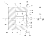
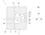
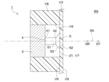
- FIG. 2 is a cross-sectional view showing a schematic configuration of the ultrasonic sensor shown in FIG. 1
- FIG. 3 is a cross-sectional view showing an outline of the operation of the ultrasonic sensor shown in FIG. 2
- FIG. 3 is a cross-sectional view showing an outline of the operation of the ultrasonic sensor shown in FIG. 2
- FIG. 10 is a perspective view showing the appearance of a vehicle equipped with an ultrasonic sensor according to a second embodiment
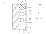
- 6 is a cross-sectional view showing an example of a schematic configuration of the ultrasonic sensor shown in FIG. 5;
- FIG. 5 is a cross-sectional view showing an example of a schematic configuration of the ultrasonic sensor shown in FIG. 5;
- FIG. 6 is a cross-sectional view showing another example of the schematic configuration of the ultrasonic sensor shown in FIG. 5;
- FIG. FIG. 6B is a cross-sectional view showing an overview of the operation of the ultrasonic sensor shown in FIG. 2, FIG. 6A, or FIG. 6B;
- FIG. 8 is a cross-sectional view showing a schematic configuration and an outline of operation according to a modified example of the ultrasonic sensor shown in FIG. 7;
- FIG. 8 is a cross-sectional view showing a schematic configuration and an outline of operation according to another modified example of the ultrasonic sensor shown in FIG. 7;
- FIG. 8 is a cross-sectional view showing a schematic configuration and outline of operation according to still another modification of the ultrasonic sensor shown in FIG. 7;
- FIG. 6B is a cross-sectional view showing a schematic configuration according to a modified example of the ultrasonic sensor shown in FIG. 2, FIG. 6A, or FIG. 6B;
- FIG. 7 is a cross-sectional view showing a schematic configuration according to another modified example of the ultrasonic sensor shown in FIG. 2, FIG. 6A, or FIG. 6B;
- FIG. 8 is a cross-sectional view showing a schematic configuration according to still another modification of the ultrasonic sensor shown in FIGS. 2, 6A, or 6B;
- FIG. 8 is a cross-sectional view showing a schematic configuration according to still another modification of the ultrasonic sensor shown in FIGS. 2, 6A, or 6B;
- FIG. 8 is a cross-sectional view showing a schematic configuration according to still another modification of the ultrasonic sensor shown in FIGS. 2, 6A, or 6B;
- FIG. 8 is a cross-sectional view showing a schematic configuration according to still another modification of the ultrasonic sensor shown in FIGS. 2, 6A, or 6B;
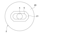
- FIG. 10 is a rear view showing a configuration example of a sensor housing and a vibration converting section in still another modified example of the ultrasonic sensor shown in FIG. 2, FIG. 6A, or FIG. 6B;
- FIG. 17 is a cross-sectional view showing an overview of the operation of the ultrasonic sensor including the sensor housing and the vibration converter shown in FIG. 16;
- FIG. 17 is a cross-sectional view showing an overview of the operation of the ultrasonic sensor including the sensor housing and the vibration converter shown in FIG. 16;
- FIG. 8 is a cross-sectional view showing a schematic configuration according to still another modification of the ultrasonic sensor shown in FIGS. 2, 6A, or 6B;
- FIG. 8 is a cross-sectional view showing a schematic configuration according to still another modification of the ultrasonic sensor shown in FIGS. 2, 6A, or 6B;
- FIG. 8 is a cross-sectional view showing a schematic configuration according to still another modification of the ultrasonic sensor shown in FIGS. 2, 6A, or 6B;
- FIG. 8 is a cross-sectional view showing a schematic configuration according to still another modification of the ultrasonic sensor shown in FIGS. 2, 6A, or 6B;
- FIG. 8 is a cross-sectional view showing a schematic configuration according to still another modification of the ultrasonic sensor shown in FIGS.
- FIG. 8 is a cross-sectional view showing a schematic configuration according to still another modification of the ultrasonic sensor shown in FIGS. 2, 6A, or 6B; It is a sectional view showing a schematic structure of an ultrasonic sensor concerning a third embodiment.
- FIG. 26 is a cross-sectional view showing a schematic configuration according to a modified example of the ultrasonic sensor shown in FIG. 25; It is a sectional view showing a schematic structure of an ultrasonic sensor concerning a fourth embodiment. It is a sectional view showing a schematic structure of an ultrasonic sensor concerning a fifth embodiment.
- FIG. 29 is a cross-sectional view showing a schematic configuration according to a modified example of the ultrasonic sensor shown in FIG. 28; FIG.
- FIG. 11 is a cross-sectional view showing a schematic configuration of an ultrasonic sensor according to a sixth embodiment
- FIG. 31 is a cross-sectional view showing a schematic configuration according to a modified example of the ultrasonic sensor shown in FIG. 30
- FIG. 31 is a cross-sectional view showing a schematic configuration according to another modified example of the ultrasonic sensor shown in FIG. 30
- 31 is a cross-sectional view showing a schematic configuration according to still another modification of the ultrasonic sensor shown in FIG. 30
- FIG. FIG. 11 is a cross-sectional view showing a schematic configuration of an ultrasonic sensor according to a seventh embodiment
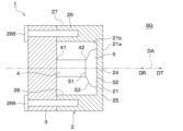
- 1 is a functional block diagram showing one configuration example of an object detection device using an ultrasonic sensor according to the present disclosure
- FIG. 11 is a cross-sectional view showing a schematic configuration of an ultrasonic sensor according to a modification;
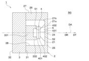
- FIG. 11 is a cross-sectional view showing a schematic configuration of an ultrasonic sensor according to a modification;
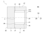
- FIG. 11 is a cross-sectional view showing a schematic configuration of an ultrasonic sensor according to a modification;
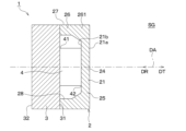
- FIG. 11 is a cross-sectional view showing a schematic configuration of an ultrasonic sensor according to a modification;
- FIG. 11 is a cross-sectional view showing a schematic configuration of an ultrasonic sensor according to a modification;
- FIG. 11 is a cross-sectional view showing a schematic configuration of an ultrasonic sensor according to a modification;
- FIG. 11 is a cross-sectional view showing a schematic configuration of an ultrasonic sensor according to a modification;
- FIG. 11 is a cross-sectional view showing a schematic configuration of an ultrasonic sensor according to a modification;
- FIG. 11 is a cross-sectional view showing a
- FIG. 11 is a cross-sectional view showing a schematic configuration of an ultrasonic sensor according to a modification;
- FIG. 11 is a cross-sectional view showing a schematic configuration of an ultrasonic sensor according to a modification;
- FIG. 11 is a cross-sectional view showing a schematic configuration of an ultrasonic sensor according to a modification;
- FIG. 11 is a cross-sectional view showing a schematic configuration of an ultrasonic sensor according to a modification;
- FIG. 11 is a cross-sectional view showing a schematic configuration of an ultrasonic sensor according to a modification;
- FIG. 11 is a cross-sectional view showing a schematic configuration of an ultrasonic sensor according to a modification;
- FIG. 11 is a cross-sectional view showing a schematic configuration of an ultrasonic sensor according to a modification;
- the ultrasonic sensor 1 is mounted on a vehicle V as a moving object, and responds to the presence of an object (for example, an obstacle) existing in the external space SG around the vehicle V. configured to generate and output a sensing signal; That is, the ultrasonic sensor 1 has a configuration as a vehicle-mounted clearance sonar to which the vehicle V is mounted.
- the vehicle V is typically a so-called four-wheel vehicle and has a box-shaped body V1.
- the vehicle body V1 includes a vehicle body panel V2 and a bumper V3, which are plate-like body parts that form an outer panel.
- the bumpers V3 are provided at the front and rear ends of the vehicle body V1.
- the ultrasonic sensor 1 is configured to be attached to the bumper V3.
- a state in which the ultrasonic sensor 1 is mounted on the vehicle V by being attached to the bumper V3 is hereinafter referred to as a “mounted state”.
- a plurality of (for example, four) ultrasonic sensors 1 are attached to the front bumper, that is, the bumper V3 on the front side of the vehicle body V1.
- a plurality of ultrasonic sensors 1 attached to the front bumper are arranged at different positions at least in the vehicle width direction.
- a plurality of (for example, four) ultrasonic sensors 1 are attached to a rear bumper, that is, a bumper V3 on the rear side of the vehicle body V1.
- the bumper V3 is provided with a mounting hole V4, which is a through hole for mounting the ultrasonic sensor 1 thereon.
- FIG. 2 shows one of the plurality of ultrasonic sensors 1 attached to the bumper V3 in its mounted state.
- the "adhesive layer” includes an adhesive layer (i.e., a synthetic resin layer formed by solidifying an adhesive) and a double-sided tape layer (i.e., by peeling the release paper from both the front and back sides of the double-sided tape). appearing adhesive layer), etc.
- the ultrasonic sensor 1 is configured to transmit and/or receive ultrasonic waves. That is, the ultrasonic sensor 1 has a transmission function of transmitting a transmission wave, which is an ultrasonic wave, to the external space SG along the directional axis DA, and/or a reception function of receiving a reflected wave of the transmission wave from an object from the external space SG. is configured to play
- the "directive axis" is a virtual straight line extending from the ultrasonic sensor 1 along the traveling direction of the transmitted wave, and serves as a reference for the directivity angle.
- the "orientation axis" may also be referred to as “orientation central axis" or “detection axis”.
- a “directivity angle” may also be referred to as a "half-value angle.”
- the ultrasonic sensor 1 receives from the external space SG received waves including reflected waves of transmitted waves from objects existing around the vehicle V, and generates and outputs a detection signal according to the reception result of the received waves. is configured as
- the axial direction includes the transmission direction DT and the reception direction DR.
- a transmission direction DT is a direction parallel to the axial direction and directed from the ultrasonic sensor 1 to the external space SG. That is, the transmission direction DT is the direction in which the transmission wave travels on the directivity axis DA.
- the receiving direction DR is the direction opposite to the transmitting direction DT, which is parallel to the axial direction and directed from the external space SG to the ultrasonic sensor 1 . That is, the receiving direction DR is the direction in which the received wave travels on the directivity axis DA.
- the “tip in the axial direction” of a component refers to the end of the component on the transmission direction DT side.
- the “proximal end in the axial direction” of a component refers to the end of the component on the receiving direction DR side.
- An arbitrary direction orthogonal to the axial direction is called an "in-plane direction”.
- the “in-plane direction” is a direction parallel to a virtual plane normal to the directivity axis DA.
- a shape of a certain component projected onto the virtual plane is called an “in-plane shape”. Note that the in-plane direction includes the "radial direction”.
- the “radial direction” is the direction in which a half-line extends when a half-line is drawn in the virtual plane starting from the point of intersection between the virtual plane and the directivity axis DA.
- the “radial direction” is the radial direction of a circle drawn in the virtual plane with the point of intersection between the virtual plane and the directivity axis DA as the center.
- the bumper V3 has a bumper outer surface V5 and a bumper inner surface V6.
- the bumper outer surface V5 is provided so as to face an external space SG, which is a space outside the vehicle V.
- the bumper inner surface V6 is the rear surface of the bumper outer surface V5.
- the mounting hole V4 is provided so as to open at the bumper outer surface V5 and the bumper inner surface V6.
- the mounting hole V4 is formed as a circular hole having the directivity axis DA as a central axis.
- An ultrasonic sensor 1 includes a sensor housing 2 , a fixing section 3 , a conversion element 4 and a vibration conversion section 5 .
- a specific configuration example of each part in the ultrasonic sensor 1 according to the present embodiment will be described below.
- the sensor housing 2 is formed in the shape of a bottomed cylinder having a shape in which the tip in the axial direction of the cylindrical side wall is closed with a bottom wall and the base end is open.
- the sensor housing 2 can be made of, for example, a metal material such as aluminum or an aluminum alloy, a synthetic resin material such as polypropylene, polyacetal (that is, POM) or acrylic resin, a composite material such as CFRP, or the like.
- POM is an abbreviation for Polyoxymethylene.
- CFRP is an abbreviation for Carbon Fiber Reinforced Plastics.
- the sensor housing 2 has a diaphragm 21 .
- the diaphragm 21 is formed in a plate shape having a plate thickness direction along the directivity axis DA. That is, the diaphragm 21 is formed by the bottom wall of the bottomed cylindrical sensor housing 2 that intersects the directivity axis DA.
- Diaphragm 21 has an arbitrary in-plane shape such as circular, elliptical, and polygonal.
- the diaphragm 21 has an outer surface 21a exposed to the external space SG in the mounted state, and an inner surface 21b that is the reverse side of the outer surface 21a.
- the diaphragm 21 has a flat plate shape with a constant thickness as a typical configuration example. Therefore, in this specific example, the outer surface 21 a and the inner surface 21 b are provided as a pair of main surfaces of the diaphragm 21 .
- a “principal surface” is a surface of a plate-like portion or member whose normal direction is the plate thickness direction. That is, the outer surface 21a and the inner surface 21b are provided so as to be orthogonal to the directivity axis DA.
- the present disclosure is not limited to such a configuration.
- a non-connecting portion 22 and a connecting portion 23 may be formed on the diaphragm 21 .
- the non-connecting portion 22 is a portion on the outer edge side in the radial direction of the diaphragm 21 and is a portion where the inner surface 21b of the diaphragm 21 and the vibration conversion portion 5 do not face each other.
- the connecting portion 23 is a portion inside the non-connecting portion 22 in the radial direction of the diaphragm 21, where the inner surface 21b and the vibration converting portion 5 face each other.
- the diaphragm 21 is provided so that it can be ultrasonically vibrated in such a manner that the center portion 24 in the in-plane direction moves along the directivity axis DA.
- the sensor housing 2 has a support portion 26 that supports the outer edge portion 25 of the diaphragm 21 in the in-plane direction. That is, the support portion 26 is formed by a side wall of the bottomed cylindrical sensor housing 2 surrounding the directivity axis DA.
- the diaphragm 21 has a plate thickness smaller than the dimension of the support portion 26 in the axial direction. Diaphragm 21 may be made of a softer material than support 26 .
- the outer edge portion 25 of the diaphragm 21 is coupled to the tip portion of the support portion 26 in the axial direction.
- the diaphragm 21 is provided so as to be capable of ultrasonic vibration in a primary vibration mode in which the outer edge portion 25 in the in-plane direction is a node and the center portion 24 is an antinode.
- the support portion 26 has an outer peripheral surface 27 and an inner peripheral surface 28 .
- the outer peripheral surface 27 is formed in a cylindrical shape. At least the tip portion of the outer peripheral surface 27 in the axial direction is accommodated inside the mounting hole V4 in the mounted state.
- the inner peripheral surface 28 is formed in the shape of a cylindrical inner surface facing the directivity axis DA.
- the fixing portion 3 is provided so as to close the opening on the base end side in the axial direction of the sensor housing 2 .
- the fixed part 3 can be made of a metal material, a synthetic resin material, a composite material, or the like.
- the fixing portion 3 has a fixing surface 31 and a back surface 32 .
- the fixing surface 31 is provided so as to face the inner surface 21 b of the diaphragm 21 .
- the fixing surface 31 is joined to the base end portion in the axial direction of the support portion 26 via a joining layer such as an adhesive.
- Such a bonding layer is formed with a thickness that is sufficiently small (for example, 100 ⁇ m or less or less than one-eighth of the wavelength) with respect to the wavelength of the transmission/reception wave.
- the back surface 32 is provided on the back side of the fixing surface 31 .
- the fixed portion 3 has a plate-like shape with a constant plate thickness as a typical configuration example. Therefore, in this specific example, the fixed surface 31 and the rear surface 32 are provided as a pair of main surfaces of the fixed portion 3 that intersect (that is, are orthogonal to) the directivity axis DA. However, it is clear from the description of modified examples and the like below that the present disclosure is not limited to such a configuration.
- a circuit board (not shown) electrically connected to the vibration converting section 5 is provided on the rear surface 32 side.
- the conversion element 4 and the vibration conversion section 5 are housed in a space surrounded by the sensor housing 2 and the fixing section 3 by joining the base end portion of the support section 26 in the axial direction and the fixing surface 31 .
- the conversion element 4 and the vibration conversion section 5 are arranged adjacent to each other on the directivity axis DA.
- the fixed part 3, the conversion element 4, and the vibration conversion part 5 are arranged in this order along the transmission direction DT.
- the sensor housing 2, the fixing portion 3, the conversion element 4, and the vibration conversion portion 5 constitute a so-called ultrasonic transducer as an ultrasonic speaker and/or an ultrasonic microphone.
- the conversion element 4 is composed of an electro-mechanical energy conversion element that performs the function of converting ultrasonic vibrations along the axial direction and electrical signals.
- a piezoelectric element, a monomorph type or bimorph type vibrator, a Langevin type vibrator, or the like can be used as the conversion element 4.
- a monomorph type or bimorph type vibrator has a structure in which a piezoelectric element is attached to a plate material.
- a Langevin vibrator has a configuration in which a plate-shaped piezoelectric element having a thickness direction along an axial direction is sandwiched between a pair of blocks.
- the conversion element 4 has a base end portion 41 that is one end portion in the axial direction and a tip portion 42 that is the other end portion.
- the base end portion 41 is fixed to the fixing surface 31 of the fixing portion 3 via a bonding layer such as an adhesive layer.
- a bonding layer is formed with a thickness that is sufficiently small (for example, 100 ⁇ m or less or less than one-eighth of the wavelength) with respect to the wavelength of the transmission/reception wave.
- the tip portion 42 protrudes from the fixed portion 3 toward the tip side in the axial direction, that is, in the transmission direction DT.
- the fixing portion 3 is arranged so as to be closer to the proximal end portion 41 than the distal end portion 42 of the conversion element 4 , and is provided so as to support the conversion element 4 in a fixed manner.
- the ultrasonic sensor 1 is present on the transmission direction DT side (that is, the direction from the proximal end portion 41 to the distal end portion 42) of the transducer element 4 by applying a drive signal, which is an electric signal, to the transducer element 4. It is configured to have a transmission function of transmitting a transmission wave to the external space SG.
- the ultrasonic sensor 1 is configured to perform a reception function of converting ultrasonic vibrations transmitted from the external space SG to the conversion element 4 by reception of the received wave into a reception signal that is an electric signal by the conversion element 4.
- the vibration converter 5 is provided between the diaphragm 21 and the conversion element 4 .
- the vibration conversion section 5 is connected to the tip portion 42 of the conversion element 4 so as to be able to transmit vibration.
- the vibration conversion unit 5 is connected to the diaphragm 21 so as to be able to transmit vibration. That is, the vibration conversion unit 5 has a function of converting one of ultrasonic vibration (e.g., stretching vibration along the axial direction) in the conversion element 4 and ultrasonic vibration (e.g., membrane vibration) in the diaphragm 21 to the other.
- ultrasonic vibration e.g., stretching vibration along the axial direction
- ultrasonic vibration e.g., membrane vibration
- the ultrasonic sensor 1 the ultrasonic vibration generated in the conversion element 4 by the application of the driving signal is transmitted from the conversion element 4 to the vibration plate 21 via the vibration conversion unit 5, and the vibration plate 21 ultrasonically vibrates.
- the ultrasonic sensor 1 converts the ultrasonic vibration transmitted from the diaphragm 21 excited by the reception of the received wave from the external space SG to the transducer element 4 via the vibration transducer 5 into a received signal at the transducer element 4. It is configured to perform a transforming receiving function.
- the vibration converting portion 5 has a first facing surface 51 close to the tip portion 42 of the conversion element 4 and a second facing surface 52 close to the diaphragm 21 on the back side of the first facing surface 51 .
- the first opposing surface 51 and the second opposing surface 52 are formed in a planar shape that intersects (that is, is perpendicular to) the directivity axis DA. That is, the first opposing surface 51 and the second opposing surface 52 are provided substantially parallel to each other.
- the first opposing surface 51 is bonded to the tip portion 42 of the conversion element 4 via a bonding layer such as an adhesive layer.
- the second facing surface 52 is bonded to the inner surface 21b of the connection portion 23 of the diaphragm 21 via a bonding layer such as an adhesive layer.
- a bonding layer such as an adhesive layer.
- These bonding layers are formed to have a thickness that is sufficiently small (for example, 100 ⁇ m or less or less than 1/8 of the wavelength) with respect to the wavelength of the transmitted and received waves.
- the vibration converting portion 5 is formed so that the first opposing surface 51 and the second opposing surface 52 have different areas, so that the function of converting the area of the vibration surface can be achieved. Specifically, as shown in FIG. 2 , in this specific example, the vibration converting portion 5 is formed so that the second facing surface 52 has a larger area than the first facing surface 51 . ing. For this reason, the end surface 53 provided between the first opposing surface 51 and the second opposing surface 52 is formed in a partial pyramidal surface shape having a straight generatrix whose in-plane shape increases toward the transmission direction DT. It is
- the ultrasonic sensor 1 has a configuration such that the vibration mode of the diaphragm 21 is limited to the primary vibration mode by the vibration converter 5 . Specifically, when the vibration conversion unit 5 is urged in the transmission direction DT by the conversion element 4 in the transmission function, the connection portion 23 of the diaphragm 21 can be efficiently pushed out in the transmission direction DT. It has a hardness greater than that of the diaphragm 21 .
- "Hard” as used herein means having a high density and/or a high Young's modulus. In general, the higher the density and the higher the Young's modulus, the higher the acoustic impedance.
- the vibration converter 5 is configured to behave rigidly when vibration is transmitted between the diaphragm 21 and the conversion element 4 .
- the vibration conversion unit 5 is arranged such that the second opposing surface 52 moves in parallel in the axial direction with the ultrasonic vibration of the conversion element 4 without bending (that is, without changing the in-plane shape). and is adapted to ultrasonically vibrate in a manner.
- the vibration converter 5 is configured to increase the efficiency of vibration transmission between the diaphragm 21 and the conversion element 4 .
- the vibration conversion unit 5 is made of a material having an acoustic impedance equal to or higher than the diaphragm 21 and equal to or lower than the conversion element 4 .
- the acoustic impedance of the conversion element 4 is assumed to be greater than the acoustic impedance of the diaphragm 21 .
- the vibration conversion unit 5 may be made of a metal material such as aluminum, an aluminum alloy, or a magnesium alloy, a synthetic resin material such as PBT or a glass epoxy resin, a composite material such as CFRP, or the like.
- PBT is an abbreviation for polybutylene terephthalate. If the vibration converting section 5 is made of a conductive material such as metal, it can be set to a predetermined potential (for example, a reference potential such as ground potential).
- the vibration converting portion 5 is formed so as to suppress spurious vibrations in the diaphragm 21 by having the second opposing surface 52 have an area corresponding to the area of the diaphragm 21 (that is, the inner surface 21b). That is, the vibration converting portion 5 has a shape such that the outer diameter of the second opposing surface 52 is equal to or smaller than the outer diameter of the inner surface 21b and the difference between the two is minimized.
- the width in the radial direction of the non-connecting portion 22, that is, the half value of the difference between the outer diameter of the inner surface 21b and the outer diameter of the second facing surface 52 is less than the half value of the wavelength of the transmitted and received waves. It is joined to the diaphragm 21 so that it becomes.
- a driving signal is applied to the conversion element 4 at the time of transmission.
- the transducer element 4 is ultrasonically vibrated in such a manner that it expands and contracts in the axial direction.
- the conversion element 4 is axially stretched more than the state shown in FIG.
- the base end portion 41 of the conversion element 4 is fixed to the fixed portion 3 fixedly supported by the bumper V3. Therefore, as shown in FIG. 3, the tip portion 42 of the conversion element 4 moves in the transmission direction DT by extending the conversion element 4 in the axial direction.
- the vibration conversion unit 5 is urged in the transmission direction DT by the distal end portion 42 of the conversion element 4 .
- the vibration converter 5 moves in the transmission direction DT while maintaining the planar state of the second facing surface 52 joined to the diaphragm 21 .
- the connection portion 23 of the diaphragm 21 is pushed out in the transmission direction DT while maintaining the joint surface shape with the second opposing surface 52 .
- the conversion element 4 when a negative voltage is applied, the conversion element 4 is axially compressed more than the state shown in FIG.
- the base end portion 41 of the conversion element 4 is fixed to the fixed portion 3 fixedly supported by the bumper V3. Therefore, as shown in FIG. 4, the tip portion 42 of the conversion element 4 is moved in the receiving direction DR by compressing the conversion element 4 in the axial direction.
- the vibration conversion unit 5 is urged in the reception direction DR by the tip portion 42 of the conversion element 4 .
- the vibration converter 5 moves in the receiving direction DR while maintaining the planar state of the second facing surface 52 joined to the diaphragm 21 .
- the connecting portion 23 of the diaphragm 21 is pulled in the reception direction DR while maintaining the joint surface shape with the second opposing surface 52 .
- the diaphragm 21 ultrasonically vibrates in the primary vibration mode with the outer edge portion 25 as a node and the center portion 24 as an antinode.
- the vibration mode of the diaphragm 21 is limited to the primary vibration mode by the vibration converter 5 .
- the vibration plate 21 and the support portion 26 are formed.
- substantially only the diaphragm 21 can be vibrated. This makes it possible to achieve good transmission/reception characteristics, that is, high output and/or high sensitivity.
- the vibration of the diaphragm 21 in the manner described above can be realized in a non-resonant manner. Therefore, it is possible to realize any transmission/reception frequency. That is, for example, it is possible to adjust the directivity by making the transmission frequency variable. Specifically, in the case of the primary vibration mode, it is known that the proportional relationship of directivity angle ⁇ wavelength/vibration length is approximately established. Therefore, narrow directivity is realized by increasing the frequency. On the other hand, by lowering the frequency, wide directivity is realized. Alternatively, it is possible to satisfactorily suppress the influence of changes in directivity due to temperature changes.
- the sensor housing 2 that is, the diaphragm 21 and the support portion 26, are made of a synthetic resin material whose physical properties are likely to change due to changes in temperature, it is possible to more stably achieve the desired directivity. It becomes possible.
- the conventional technology there is a trade-off between narrow directivity and broadband. That is, for example, when the outer diameter of the diaphragm 21 is increased, the directivity is narrowed and the resonance frequency is lowered. On the other hand, when the outer diameter of the diaphragm 21 is reduced, the directivity becomes wider and the resonance frequency becomes higher.
- the frequency band that can be transmitted and received depends on the electro-mechanical energy conversion characteristics of the joint between the sensor housing 2 including the diaphragm 21 and the piezoelectric element.
- the conversion element 4 as the vibration generating section and the diaphragm 21 as the directivity designing section are separated, the trade-off relationship between the directivity and the band is eliminated. , the degree of freedom in design is improved. Specifically, for example, it is possible to realize an ultrasonic sensor 1 with narrow directivity and wide band. In addition, it is clear that the ultrasonic sensor 1 with wide directivity and wide band can also be realized.
- the vibration converting portion 5 by forming the vibration converting portion 5 from a conductive material such as metal and setting it to a predetermined potential (for example, a reference potential such as ground potential), the conversion element 4 can be electromagnetically shielded satisfactorily.
- a predetermined potential for example, a reference potential such as ground potential
- EMC is an abbreviation for Electromagnetic Compatibility.
- suitable EMC countermeasures can be realized when the sensor housing 2 is integrally formed of a non-conductive material (for example, synthetic resin).
- the present embodiment employs a configuration in which the diaphragm 21 is ultrasonically vibrated in such a manner that the diaphragm 21 is pushed out and pulled in on its surface.
- desired directivity can be more stably achieved, and transmission/reception characteristics can be further improved. It should be noted that it is not always necessary to pull in, and "push or return" may be used.
- the bumper V3 is not provided with the mounting hole V4 shown in FIG. That is, the ultrasonic sensor 1 according to this embodiment can be attached to the bumper V3 without forming the attachment hole V4 in the bumper V3. In other words, the ultrasonic sensor 1 can be easily "retrofitted” to the bumper V3 of the non-equipped vehicle, which is the vehicle V once shipped from the factory without the ultrasonic sensor 1 installed.
- the ultrasonic sensor 1 according to this embodiment having such a configuration is covered from the outside by a bumper V3 that does not have a mounting hole V4 in the mounted state. Therefore, such a configuration may hereinafter be referred to as an "invisible sonar configuration.”
- the ultrasonic sensor 1 is configured such that a part of the bumper V3 is used as the diaphragm 21 and ultrasonic vibrations in the diaphragm 21 are used to transmit and/or receive ultrasonic waves.
- FIG. 6A shows an example of such a configuration.
- the diaphragm 21 is constituted by a vibrating portion V7 that is part of the bumper V3.
- the vibration plate 21, that is, the vibrating portion V7 includes a damping portion V8, which is a cylindrical, ring-shaped, wall-shaped, or wall-shaped component arranged so as to surround the directional axis DA, and an adhesive layer or the like.
- the damping portion V8 is provided integrally or divided into a plurality of parts in the circumferential direction surrounding the directivity axis DA so as to surround the directivity axis DA.
- the “circumferential direction” surrounding the directivity axis DA refers to a single closed curve that surrounds the directivity axis DA when drawn on a virtual plane intersecting (that is, typically orthogonal to) the directivity axis DA. The upper point is the direction of the trajectory moving on the single closed curve.
- a “single closed curve” is a closed curve that does not intersect with itself in a three-dimensional Euclidean space, and can also be called a simple closed curve or a Jordan curve.
- a “single closed curve” includes polygons such as rectangles.
- the damping section V8 is composed of at least one component arranged to surround the directivity axis DA.
- the damping portion V8 is composed of a plurality of parts arranged in the circumferential direction, slits or gaps may be provided between adjacent parts. In this manner, the damping section V8 can be provided so as to intermittently or discontinuously surround the directivity axis DA in the circumferential direction.
- the damping portion V8 when the damping portion V8 is formed in a cylindrical shape that continuously surrounds the directivity axis DA in the circumferential direction, one or more slits or openings may be provided in the circumferential direction.
- the vibrating portion V7 is a portion inside the damping portion V8 when the bumper V3 and the damping portion V8 are joined together.
- Such a bonding layer is formed with a thickness that is sufficiently small (for example, 100 ⁇ m or less or less than one-eighth of the wavelength) with respect to the wavelength of the transmission/reception wave.
- the vibration converting portion 5, the converting element 4, and the fixing portion 3 are accommodated in the holding surface V9, which is the inner peripheral surface of the damping portion V8.
- a sensor housing 2 composed of the damping portion V8 and the fixing portion 3 is fixed to the bumper inner surface V6.
- the damping portion V8 corresponds to the support portion 26 shown in FIG. 6B and described later.
- the vibration converter 5 is connected to the diaphragm 21, which is a part of the bumper V3, so as to be able to transmit vibrations.
- the second opposing surface 52 which is the outer surface of the vibration converting portion 5, and the bumper inner surface V6 of the diaphragm 21 are arranged so that a gap, that is, an air layer, is not generated. is in contact with or joined to.
- the vibration converting section 5 also serves as an acoustic matching layer 61 shown in FIG. 6B and described later.
- the acoustic matching layer 61 is provided between the second facing surface 52, which is the outer surface of the vibration converting section 5, and the bumper inner surface V6 of the diaphragm 21 so that a gap, that is, an air layer, does not occur. may have been That is, in this case, the acoustic matching layer 61 is sandwiched between the vibration converting section 5 and the diaphragm 21 . Specifically, for example, the acoustic matching layer 61 is fixed to one of the vibration converting section 5 and the diaphragm 21 .
- the acoustic matching layer 61 interposed between the vibration converting portion 5 and the bumper V3, ie, the diaphragm 21, is provided so as to increase the vibration transmission efficiency between them.
- the acoustic matching layer 61 is configured to maximize the vibration transmission efficiency between the vibration converting section 5 and the diaphragm 21 .
- the acoustic matching layer 61 is made of a material having an acoustic impedance equal to or higher than that of the diaphragm 21 (that is, the bumper V3) and equal to or lower than the vibration converting portion 5. As shown in FIG.
- the acoustic matching layer 61 can be made of, for example, a curable synthetic resin such as epoxy resin. Alternatively, the acoustic matching layer 61 can be formed with a thickness of 50 ⁇ m or less.
- the ultrasonic sensor 1 of this embodiment having such a configuration transmits transmission waves by vibrating a portion of the bumper V3 as the diaphragm 21 during transmission. Also, during reception when the reception function is exhibited, the vibration of the diaphragm 21 excited by the received wave is converted into an electric signal to generate a received signal. And also in this embodiment, the same effect as said 1st embodiment can be show
- the configuration example shown in FIG. 6A is a simplified version of the configuration example shown in FIG. 6B described below. Specifically, in the configuration example shown in FIG. 6A, the diaphragm 21 and the bumper V3 in the sensor housing 2 provided in the configuration example shown in FIG. 6B are integrated and supported. The portion 26 and the damping portion V8 are integrated.
- FIG. 6B shows another example of the configuration shown in FIG. 6A.
- the ultrasonic sensor 1 according to the present embodiment is configured such that a part of the bumper V3 is used as a vibrating section V7, and ultrasonic waves are transmitted and/or received using ultrasonic vibration in the vibrating section V7.
- the vibrating portion V7 includes a damping portion V8, which is a tubular, ring-shaped, fence-shaped, or wall-shaped part surrounding the directivity axis DA, and a bonding layer such as an adhesive layer. It is formed by bonding to the bumper inner surface V6 through the V6.
- the damping portion V8 is provided integrally or divided into a plurality of parts in the circumferential direction surrounding the directivity axis DA so as to surround the directivity axis DA.
- the damping section V8 is composed of at least one component arranged to surround the directivity axis DA.
- the vibrating portion V7 is a portion inside the damping portion V8 when the bumper V3 and the damping portion V8 are joined together.
- Such a bonding layer is formed with a thickness that is sufficiently small (for example, 100 ⁇ m or less or less than one-eighth of the wavelength) with respect to the wavelength of the transmission/reception wave.
- the diaphragm 21 is connected to the vibrating portion V7 so as to be able to transmit vibration.
- an acoustic matching layer 61 is provided between the outer surface 21a of the diaphragm 21 and the inner surface V6 of the bumper in the vibrating portion V7 so as not to form a gap, ie, an air layer. That is, the acoustic matching layer 61 is sandwiched between the diaphragm 21 and the vibrating portion V7. Acoustic matching layer 61 is fixed to one of diaphragm 21 and vibrating portion V7.
- the acoustic matching layer 61 interposed between the diaphragm 21 and the bumper V3, that is, the vibrating portion V7 is provided so as to increase the vibration transmission efficiency between them. That is, the acoustic matching layer 61 is configured to maximize the efficiency of vibration transmission between the diaphragm 21 and the vibrating portion V7.
- the acoustic matching layer 61 is made of a material having an acoustic impedance equal to or higher than the vibrating portion V7 and equal to or lower than the diaphragm 21.
- the ultrasonic sensor 1 of the present embodiment having such a configuration transmits transmission waves by vibrating a portion of the bumper V3 as the vibrating portion V7 during transmission. Further, during reception when the receiving function is exhibited, the vibration of the vibrating portion V7 excited by the received wave is converted into an electric signal to generate a received signal. And also in this embodiment, the same effect as said 1st embodiment can be show
- (Structure of vibration converter) 7 to 10 show changes in directivity when the structure of the vibration converting section 5 in the ultrasonic sensor 1 is changed.
- the vibration displacement of the outer surface 21a of the diaphragm 21 and the resulting propagation of the transmission wave are indicated by dotted lines.
- Directivity is also schematically indicated by a two-dot chain line. 7 to 10, the area of the second opposing surface 52 is larger than the area of the first opposing surface 51, that is, the outer diameter of the first opposing surface 51 is larger than the second It is assumed that the outer diameter of the facing surface 52 is larger.
- the diaphragm 21 is formed in a flat plate shape having a constant thickness, like the configurations shown in FIGS. 2 and 6A.
- the first opposing surface 51 and the second opposing surface 52 are formed in a plane shape parallel to each other.
- the end face 53 is formed in a partial pyramidal surface shape having a linear generatrix and having an in-plane shape that increases toward the transmission direction DT.
- a depression occurs in the traveling wave near the center, that is, the directivity axis DA, and side lobes are generated.
- the example of FIG. 8 is obtained by changing the shape of the end face 53 of the vibration converting portion 5 in the example of FIG. 7 into a convex shape.
- the depression of the traveling wave near the center, ie, the directivity axis DA is eliminated, and a plane wave is radiated. Also, side lobes are well suppressed.
- planar first opposing surface 51 and the planar second opposing surface 52 By making the planar first opposing surface 51 and the planar second opposing surface 52 parallel to each other, the efficiency of vibration transmission from the conversion element 4 to the diaphragm 21 can be enhanced.
- these parallelism and flatness can be appropriately changed within a range in which desired directivity and transmission/reception characteristics are obtained. That is, the parallelism and flatness can vary by a predetermined degree within the range of manufacturing errors and allowable deviations. Alternatively, these parallelism and flatness may be intentionally adjusted in order to achieve desired directivity and transmission/reception characteristics.
- the example of FIG. 9 is obtained by changing the shape of the second facing surface 52 of the vibration conversion unit 5 in the example of FIG.
- the depression of the traveling wave near the center, that is, the directivity axis DA is eliminated, and a convex spherical wave is radiated in the transmission direction DT.
- the directivity is wider than in the example of FIG.
- the sidelobes are suppressed even better than in the example of FIG.
- the shape of the second facing surface 52 of the vibration converter 5 in the example of FIG. 8 is changed to a concave shape, that is, a curved surface that is concave in the transmission direction DT, contrary to the example of FIG. changed to
- a relatively large dip occurs in the traveling wave near the center, ie, the directivity axis DA.
- the sound pressure of the transmission wave in the front direction that is, around the directivity axis DA is reduced by interference.
- Such directivity makes it possible to satisfactorily detect road surface steps and ceiling protrusions.
- FIGS. 2 and 6A show configurations in which the cost of the ultrasonic sensor 1 shown in FIGS. 2 and 6A is reduced.
- the cost can be reduced.
- the vibration converter 5 can be seamlessly and integrally formed with the diaphragm 21 using the same material.
- the cost can be reduced by using a thin-plate piezoelectric element as the conversion element 4 .
- the configurations shown in FIG. 2, FIG. 6A, etc. correspond to high receiving sensitivity and narrow directivity. That is, such a configuration is preferably applied to a narrow-directivity receiving sensor.
- a “receiving sensor” refers to the ultrasonic sensor 1 that has a receiving function but does not have a transmitting function.
- the ultrasonic sensor 1 which does not have a receiving function but has a transmitting function is called a "transmitting sensor”.
- the ultrasonic sensor 1 having both a transmission function and a reception function is called a "transmission/reception integrated sensor”.
- the outer diameter of the diaphragm 21 is made small, and the second facing surface 52 of the vibration converting portion 5 has a larger area, that is, the outer diameter, than the first facing surface 51 . is formed so that the Such a configuration is preferably applied to a wide directivity receiving sensor.
- the thickness, that is, the diameter, of the support portion 26 increases toward the distal end side in the axial direction, that is, toward the transmission direction DT. It can be formed to have a large directional dimension.
- the support portion 26 has an outer peripheral surface 27 formed in a cylindrical surface shape, and an inner peripheral surface 28 having a straight generatrix and having a smaller diameter toward the transmission direction DT. It is formed in a truncated conical surface shape.
- the configuration shown in FIG. 14 is such that the outer diameter of the diaphragm 21 is increased, and the vibration converting portion 5 is arranged so that the second facing surface 52 has a smaller area, that is, the outer diameter, than the first facing surface 51 . It is formed in Such a configuration corresponds to high transmission power and narrow directivity. That is, such a configuration is preferably applied to a narrow-directivity transmission sensor.
- a tapered portion 261 may be provided at the tip portion of the support portion 26 in the axial direction in order to suppress spurious vibration.
- the tapered portion 261 is formed so that its thickness, that is, the radial dimension, increases toward the distal end side in the axial direction, that is, toward the transmission direction DT.
- the configuration shown in FIG. 15 is such that the outer diameter of the diaphragm 21 is made small, and the vibration converting portion 5 is arranged so that the second facing surface 52 has a smaller area, that is, the outer diameter, than the first facing surface 51 . It is formed in Such a configuration supports high transmission power and wide directivity. That is, such a configuration is preferably applied to a wide directivity transmission sensor. Also in such a configuration, a tapered portion 261 may be provided at the distal end portion of the support portion 26 in the axial direction in order to suppress spurious vibration.
- the diaphragm 21 has a longitudinal direction in the first in-plane direction (that is, the horizontal direction in the drawing) and a lateral direction in the second in-plane direction (that is, the vertical direction in the drawing). It has an in-plane shape (for example, an elliptical shape, an oval shape, a rectangular shape, etc.). The first in-plane direction and the second in-plane direction are in-plane directions orthogonal to each other. Further, the vibration converting portion 5 is also formed to have an in-plane shape corresponding to the in-plane shape of the diaphragm 21 .
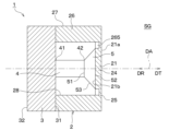
- the support portion 26 has a rigid portion 262 and an elastic portion 263 .
- the rigid portion 262 is a portion closer to the base end than the elastic portion 263 in the axial direction of the support portion 26 and is made of a rigid material such as metal.
- the elastic portion 263 is the tip portion in the axial direction of the support portion 26 and is made of an elastomer material such as silicone rubber.
- the rigid part 262 and the elastic part 263 can be joined by a joining layer such as an adhesive.
- the elastic portion 263 may have a concave portion 264 that accommodates the outer end portion of the diaphragm 21 in the radial direction.
- a slit 265 may be provided in the sensor housing 2 as shown in FIGS.
- transmission/reception characteristics that is, transmission output and reception sensitivity can be improved.
- the slit 265 is formed at the tip of the support portion 26 in the axial direction so as to open toward the direction axis DA on the inner peripheral surface 28 of the support portion 26 .
- the slit 265 is provided at the outer end in the radial direction of the diaphragm 21 so as to open in the reception direction DR on the inner surface 21b of the diaphragm 21.
- the slit 265 may be provided along the directivity axis DA so as to open in the receiving direction DR at the base end surface of the support portion 26 in the axial direction.
- an initial load is applied in a direction that urges the conversion element 4 toward the vibration conversion portion 5.
- the bonding layer may be omitted.
- the diaphragm 21 is displaced to the position where the initial load is canceled, and then further displaced in the receiving direction DR by the momentum of the elastic energy of the diaphragm 21 . Therefore, the voltage when the negative voltage is applied can be favorably lowered. Alternatively, good driving can be achieved without applying a negative voltage.
- conversion element structure As described above, various types of electro-mechanical energy conversion elements can be used as conversion elements 4 .
- the conversion element 4 is of a type that stretches and vibrates along the axial direction for simplification of explanation.
- the present disclosure is not limited to such aspects.
- FIG. 25 shows an example of using a plate-shaped piezoelectric element that flexures and vibrates as the conversion element 4 .
- the conversion element 4 is supported by a projecting portion 331 projecting in the transmission direction DT from the fixed surface 31 of the fixed portion 3 .
- a support projection 332 is provided on the projecting portion 331 formed in a block shape.
- the support protrusion 332 protrudes in the transmission direction DT from the distal end surface of the projecting portion 331 in the axial direction. Further, the support protrusion 332 is provided at the radially outer end of the projecting portion 331 .
- the conversion element 4 is configured as a monomorph-type piezoelectric element formed in a plate shape having a thickness direction in the axial direction.
- the conversion element 4 has a support plate 401 and a piezoelectric thin plate 402 .
- the support plate 401 is a plate-like member having a thickness direction in the axial direction, and is made of metal or the like.
- the support plate 401 is provided as a so-called doubly supported beam in which both ends in the in-plane direction are supported by the support projections 332 in a cross-sectional view.
- the piezoelectric thin plate 402 is a piezoelectric element plate formed to have substantially the same in-plane shape as the support plate 401 and is joined to the support plate 401 .
- the conversion element 4 is provided so as to ultrasonically vibrate in a mode of flexural vibration with a central portion 431 in the in-plane direction as a node or antinode. That is, the fixed portion 3 is configured to fixedly support the fixed end portion 432 that is the end portion of the conversion element 4 in the in-plane direction. According to such a configuration, the resonance design of the conversion element 4 makes it possible to obtain a high transmission output or a high reception sensitivity.
- FIG. 26 also shows an example of using a plate-shaped piezoelectric element that flexures and vibrates as the conversion element 4 .
- the projecting portion 331 is formed in a tubular shape.
- the conversion element 4 has a configuration as a monomorph type or bimorph type piezoelectric element formed in a plate shape having a thickness direction in the axial direction.
- the conversion element 4 is shown as a single plate for the sake of simplification of illustration. In the configuration shown in FIG. 26, the size of the conversion element 4 in the in-plane direction is made larger than in the configuration shown in FIG. 25 in order to further increase the output or sensitivity.
- the amount of displacement in the axial direction of the vibration converting portion 5 that is, the second opposing surface 52 is generated corresponding to the amount of deflection of the conversion element 4 . That is, the vibration due to the bending motion of the conversion element 4 is converted by the vibration conversion portion 5 into axial vibration due to the parallel movement of the second opposing surface 52 .
- the conversion element 4 provided in the transmission sensor for example, a laminated piezoelectric element, a monomorph oscillator, a bimorph oscillator, a Langevin oscillator, or the like can be preferably used.
- the conversion element 4 provided in the receiving sensor for example, a single-layer piezoelectric element, a monomorph oscillator, a bimorph oscillator, or the like can be preferably used.
- FIG. 27 shows a configuration in which the function of one conversion element 4 can be switched between a multilayer piezoelectric element and a single-layer piezoelectric element in order to avoid such a trade-off. That is, as shown in FIG. 27, the transducer element 4 includes a plurality of piezoelectric layers 441, at least one insulating layer 442, one reference electrode layer 443, one drive electrode layer 444, and at least one It has two internal reference electrode layers 445 and at least one internal drive electrode layer 446 .
- the piezoelectric layer 441 is made of a piezoelectric material such as lead zirconate titanate (that is, PZT).
- the multiple piezoelectric layers 441 are arranged in the axial direction.
- the insulating layer 442 is made of an insulating non-piezoelectric material (for example, alumina ceramics), and is arranged between two piezoelectric layers 441 adjacent in the axial direction.
- the piezoelectric layer 441 and the insulating layer 442 are formed in a layer shape or a film shape having a thickness direction in the axial direction.
- the reference electrode layer 443 is provided on the tip surface in the axial direction of the conversion element 4, that is, on the tip surface in the axial direction of the one of the plurality of piezoelectric layers 441 that is arranged closest to the tip side in the axial direction.
- the driving electrode layer 444 is provided on the axial base end surface of the conversion element 4 , that is, on the axial base end surface of the piezoelectric layer 441 that is arranged on the most axial base end side among the plurality of piezoelectric layers 441 .
- the internal reference electrode layer 445 is provided so as to be sandwiched between the insulating layer 442 and the tip surface in the axial direction of the plurality of piezoelectric layers 441 other than the one arranged on the tip end side in the axial direction.
- the internal drive electrode layer 446 is provided so as to be sandwiched between the insulating layer 442 and the axial proximal end surface of the piezoelectric layers 441 other than the one disposed closest to the proximal end in the axial direction.
- the reference electrode layer 443, the drive electrode layer 444, the internal reference electrode layer 445, and the internal drive electrode layer 446 are formed in a layer or film having a thickness direction in the axial direction using, for example, silver paste.
- the reference electrode layer 443 and internal reference electrode layer 445 are set to the reference potential.
- a high frequency drive voltage is applied between the reference electrode layer 443 and the internal drive electrode layer 446, between the internal reference electrode layer 445 and the internal drive electrode layer 446, and between the internal reference electrode layer 445 and the drive electrode layer 444.
- a high frequency drive voltage is applied between the conversion element 4 operates as a laminated piezoelectric element.
- the voltage between the reference electrode layer 443 and the internal drive electrode layer 446 provided on both sides of the one of the plurality of piezoelectric layers 441 that is arranged on the tip end side in the axial direction. Based on this, a received signal is generated.
- other internal drive electrode layers 446 and drive electrode layers 444 are set to the reference potential. Thereby, the conversion element 4 operates as a single-layer piezoelectric element.
- the function of one conversion element 4 can be achieved by the switching operation of the control circuit (not shown) electrically connected to the conversion element 4 between the stacked piezoelectric element and the single-layer piezoelectric element. Switching becomes possible. Therefore, it is possible to realize a transmitter-receiver integrated sensor capable of achieving both high transmission output and high reception sensitivity with a simple configuration.
- FIG. 28 shows a configuration in which a transmitting element 451 having a transmitting function and a receiving element 452 having a receiving function are separately provided as the conversion element 4 . That is, the conversion element 4 includes a transmission element 451 , a reception element 452 and a connecting portion 453 .
- the transmitting element 451 for example, a laminated piezoelectric element, a monomorph oscillator, a bimorph oscillator, a Langevin oscillator, or the like can be used.
- the receiving element 452 for example, a single-layer piezoelectric element, a monomorph oscillator, a bimorph oscillator, or the like can be used.
- the connecting portion 453 is sandwiched between the transmitting element 451 and the receiving element 452 .
- the transmitting element 451, the connecting portion 453, and the receiving element 452 are arranged in this order on the directional axis DA.
- the transmission element 451 is provided on the base end portion 41 side of the conversion element 4 .
- the receiving element 452 is provided on the tip portion 42 side of the conversion element 4 .
- the connecting portion 453 has a transmitting element facing surface 454 that is a main surface facing the transmitting element 451 and a receiving element facing surface 455 that is a main surface facing the receiving element 452 .
- the transmitting element facing surface 454 and the receiving element facing surface 455 are formed in planar shapes substantially orthogonal to the directivity axis DA and parallel to each other.
- the connecting portion 453 is bonded to the transmitting element 451 via a bonding layer such as an adhesive layer on the transmitting element facing surface 454 .
- the connecting portion 453 is joined to the receiving element 452 at the receiving element facing surface 455 via a bonding layer such as an adhesive layer.
- These bonding layers are formed to have a thickness that is sufficiently small (for example, 100 ⁇ m or less or less than 1/8 of the wavelength) with respect to the wavelength of the transmitted and received waves.
- the receiving element 452 is formed with a smaller area, ie, an outer diameter, than the transmitting element 451 in the plane perpendicular to the axial direction.
- the connecting portion 453 is formed in a substantially frustum shape such that the receiving element facing surface 455 has a smaller area, ie, an outer diameter, than the transmitting element facing surface 454 .
- the connecting part 453 is configured to behave rigidly when vibration is transmitted between the transmitting element 451 and the receiving element 452 , similarly to the vibration converting part 5 .
- the connecting portion 453 transmits ultrasonic waves in such a manner that the transmitting element facing surface 454 and the receiving element facing surface 455 move in parallel in the axial direction without bending in accordance with the ultrasonic vibration of the transmitting element 451 or the receiving element 452 . arranged to vibrate.
- the transmitting element 451 can be a large-diameter laminated piezoelectric element
- the receiving element 452 can be a small-diameter single-layer piezoelectric element. Become.
- a transmitter-receiver integrated sensor capable of achieving both high transmission output and high reception sensitivity.
- the transmitting element 451 and the receiving element 452 having different in-plane shapes with the coupling portion 453, vibration transmission loss between the transmitting element 451 and the receiving element 452 can be avoided.
- FIG. 28 shows a configuration for narrow directivity in which the outer diameter of the diaphragm 21 is increased. That is, such a configuration corresponds to high transmission/reception characteristics and narrow directivity.
- FIG. 29 shows a configuration for wide directivity in which the outer diameter of diaphragm 21 is reduced. That is, such a configuration corresponds to high transmission/reception characteristics and wide directivity.
- the support portion 26 in order to suppress spurious vibration, has a first side plate portion 267, a second side plate portion 268, and a stepped portion 269, as shown in FIG. It can be formed into a square shape.
- the first side plate portion 267 is a portion on the base end side in the axial direction of the support portion 26 and has a large inner diameter corresponding to the large diameter transmitting element 451 .
- the second side plate portion 268 is a portion on the tip side in the axial direction of the support portion 26 and has a small inner diameter corresponding to the small diameter receiving element 452 .
- the stepped portion 269 is provided to connect the large inner diameter of the first side plate portion 267 and the small inner diameter of the second side plate portion 268 .
- the first side plate portion 267, the second side plate portion 268, and the stepped portion 269 have the same outer diameter. That is, the support portion 26 is formed in a substantially cylindrical shape whose inner diameter changes in the axial direction.
- FIG. 3 shows a configuration in which the same effects as those of these embodiments can be obtained while omitting the vibration converting section 5 in each of the above-described embodiments shown in FIG. 2 and the like.
- the ultrasonic sensor 1 includes a sensor housing 2, a fixing portion 3, and a conversion element 4.
- the sensor housing 2 has a diaphragm 21 .
- the diaphragm 21 has a plate thickness direction along the directivity axis DA, and is capable of ultrasonically vibrating in a manner in which a central portion 24 in an in-plane direction intersecting the directivity axis DA moves along the directivity axis DA. 26.
- the conversion element 4 is provided so that the tip portion 42 contacts the inner surface 21b of the diaphragm 21 either directly or via the bonding layer. That is, the conversion element 4 is sandwiched between the fixed portion 3 and the diaphragm 21 .
- the conversion element 4 is provided so as to ultrasonically vibrate the diaphragm 21 in such a manner that it pushes out and pulls in the plane.
- the ultrasonic vibration generated in the conversion element 4 by the application of the drive signal is transmitted from the conversion element 4 to the diaphragm 21, and the diaphragm 21 is ultrasonically vibrated.
- the ultrasonic sensor 1 performs a reception function of converting ultrasonic vibrations transmitted from the diaphragm 21, which is excited by receiving ultrasonic waves from the external space SG, to the transducer element 4 into a received signal by the transducer element 4. is configured as
- the ultrasonic sensor 1 has at least a transmission function, and the conversion element 4 is arranged so as to expand and contract in the axial direction. Assume that it has a vibrating type configuration. Then, mainly, the operation when the transmission function is exhibited, that is, the operation when the ultrasonic sensor 1 transmits the transmission wave to the external space SG will be described.
- a driving signal is applied to the conversion element 4 at the time of transmission.
- the transducer element 4 is ultrasonically vibrated in such a manner that it expands and contracts in the axial direction.
- the conversion element 4 is axially stretched more than the state shown in FIG.
- the base end portion 41 of the conversion element 4 is fixed to the fixed portion 3 fixedly supported by the bumper V3. Therefore, the tip portion 42 of the conversion element 4 moves in the transmission direction DT by extending the conversion element 4 in the axial direction.
- the diaphragm 21 is urged in the transmission direction DT by the tip portion 42 of the conversion element 4 .
- the diaphragm 21 moves in the transmission direction DT while maintaining a planar state at the junction with the tip 42 of the conversion element 4 .
- the diaphragm 21 is pushed out in the transmission direction DT while maintaining the joint surface shape with the tip portion 42 of the conversion element 4 .
- the conversion element 4 when a negative voltage is applied, the conversion element 4 is axially compressed more than the state shown in FIG.
- the base end portion 41 of the conversion element 4 is fixed to the fixed portion 3 fixedly supported by the bumper V3. Therefore, the tip portion 42 of the conversion element 4 moves in the reception direction DR by compressing the conversion element 4 in the axial direction.
- the diaphragm 21 is urged in the reception direction DR by the tip portion 42 of the conversion element 4 .
- the diaphragm 21 moves in the reception direction DR while maintaining the planar state at the joint portion of the conversion element 4 with the tip portion 42 .
- the diaphragm 21 is pulled in the reception direction DR while maintaining the joint surface shape with the tip portion 42 of the conversion element 4 .
- the diaphragm 21 ultrasonically vibrates in the primary vibration mode with the outer edge portion 25 as a node and the center portion 24 as an antinode.
- the vibration mode of the diaphragm 21 is limited to the primary vibration mode. As a result, it is possible to satisfactorily suppress the collapse of the directivity due to the generation of vibration modes higher than the primary vibration mode.
- a tapered portion 261 may be provided at the tip portion in the axial direction of the support portion 26 in order to suppress spurious vibration.
- an acoustic matching layer 61 may be provided between the conversion element 4 and the diaphragm 21 .
- the acoustic matching layer 61 may be formed in the shape of a thin plate, or may be formed relatively thick.
- the conversion element 4 may comprise a transmission element 451, a reception element 452, and a connecting portion 453.
- the receiving element 452 is formed with an area smaller than that of the transmitting element 451, as in the example of FIG.
- the arrangement order of the transmitting element 451, the receiving element 452, and the connecting portion 453 is reversed. That is, the receiving element 452, the connecting portion 453, and the transmitting element 451 are arranged in this order in the transmitting direction DT.
- the transmitting element 451 which is a large-diameter laminated piezoelectric element, pushes out the diaphragm 21 from the plane, so that the diaphragm 21 vibrates in primary vibration with the outer edge portion 25 as a node and the central portion 24 as an antinode.
- Ultrasonic vibration mode The vibration mode of the diaphragm 21 is limited to the primary vibration mode. As a result, it is possible to satisfactorily suppress the collapse of the directivity due to the generation of vibration modes higher than the primary vibration mode. In addition, such ultrasonic vibration can be realized in a non-resonant manner. Therefore, it is possible to realize any transmission/reception frequency. Furthermore, changes in transmission/reception characteristics due to temperature changes can be suppressed satisfactorily. Therefore, it is possible to realize a transmitter-receiver integrated sensor capable of achieving both high transmission output and high reception sensitivity with a simple configuration.
- the ultrasonic sensor 1 includes a sensor housing 2, a fixing section 3, a conversion element 4, and a vibration conversion section 5.
- the sensor housing 2 is formed in a bottomless tubular shape without the diaphragm 21 shown in FIG. 2 and the like.
- the vibration converting portion 5 is fixed to the tip portion 42 of the conversion element 4 so as to be connected to the tip portion 42 so as to be able to transmit vibration.
- the vibration conversion section 5 has a first facing surface 51 that is close to the tip portion 42 of the conversion element 4 and a second facing surface 52 that is the rear surface of the first facing surface 51 .
- the first opposing surface 51 is bonded to the tip portion 42 of the conversion element 4 via a bonding layer such as an adhesive layer.
- the second facing surface 52 is provided so as to face the external space SG in the mounted state.
- the vibration converting portion 5 is formed so that the second facing surface 52 has a larger area than the first facing surface 51 .
- the second opposing surface 52 is formed such that its outer diameter is slightly smaller than the inner diameter of the inner peripheral surface 28 of the support portion 26 .
- a sealing material 621 is provided so as to fill the gap between the tip portion of the vibration converting portion 5 in the axial direction and the support portion 26 .
- the sealing material 621 may be made of an elastomer material such as silicone rubber so as not to hinder the reciprocating vibration of the vibration converting section 5 in the axial direction.
- the ultrasonic vibration generated by the conversion element 4 due to the application of the drive signal is transmitted from the conversion element 4 to the vibration conversion section 5, and the vibration conversion section 5 generates an ultrasonic wave.
- the ultrasonic sensor 1 has a receiving function of converting ultrasonic vibrations transmitted from the vibration conversion unit 5 to the conversion element 4 excited by reception of ultrasonic waves from the external space SG into a reception signal by the conversion element 4. configured to play.
- the vibration converting portion 5 ultrasonically vibrates in a manner of reciprocating in the axial direction while maintaining the planar state of the first opposing surface 51 and the second opposing surface 52 . Therefore, according to this configuration, it is possible to always perform transmission and reception in the primary vibration mode. Ultrasonic vibration of this mode can be realized in a non-resonant manner. Therefore, it is possible to realize any transmission/reception frequency. Also, changes in transmission/reception characteristics due to temperature changes can be well suppressed.
- the object detection device 700 includes multiple ultrasonic sensors 1 .
- the object detection device 700 also includes a transmission circuit 701 , a reception circuit 702 , a driving signal generation section 703 , a reception signal processing section 704 and a control section 705 .
- the transmission circuit 701 is electrically connected to the ultrasonic sensor 1 so as to input a drive signal to the ultrasonic sensor 1 .
- the transmission circuit 701 has a digital/analog conversion circuit and the like. That is, the transmission circuit 701 performs processing such as digital/analog conversion on the drive signal output from the drive signal generation unit 703, and applies the generated AC voltage to the conversion element 4 in the ultrasonic sensor 1.
- the reception circuit 702 performs signal processing such as amplification and analog/digital conversion on the reception signal generated by the conversion element 4 in response to the ultrasonic wave reception result in the ultrasonic sensor 1 , and outputs the reception signal processing unit 704 . is provided to output to Specifically, the receiving circuit 702 has an amplifier circuit, an analog/digital conversion circuit, and the like.
- a transmission circuit 701 and a reception circuit 702 can be provided corresponding to each of the plurality of ultrasonic sensors 1 .
- the drive signal generator 703 is provided to generate a drive signal for outputting a transmission wave of a predetermined frequency from the ultrasonic sensor 1 and input it to the transmission circuit 701 .
- the drive signal generator 703 is configured to change the frequency of the drive signal based on the control signal output from the controller 705 .
- the received signal processing unit 704 is provided to perform various signal processing such as filtering on the received signal output from the receiving circuit 702 .
- the received signal processing section 704 is provided so as to output a processed signal, which is the result of various signal processing, to the control section 705 .
- the driving signal generating section 703 and the received signal processing section 704 can be provided in common to the plurality of ultrasonic sensors 1 .
- the control unit 705 is provided in common for the plurality of ultrasonic sensors 1 .
- the control unit 705 has a configuration as an in-vehicle microcomputer including a CPU, ROM, RAM, non-volatile rewritable memory, etc. (not shown). That is, the control unit 705 reads and executes a control program stored in the ROM or non-volatile rewritable memory, thereby controlling the operation of the object detection device 700, including the transmission/reception operations of each of the plurality of ultrasonic sensors 1.
- control unit 705 is configured as Based on the signals received by each of the plurality of ultrasonic sensors 1, the control unit 705 generates a detection signal corresponding to the existence state of an object (for example, an obstacle) existing in the external space SG, and outputs the detection signal. It is configured to output to an external device.
- the control unit 705 has a parameter acquisition unit 751, a frequency adjustment unit 752, and an object measurement unit 753 as functional configurations realized on an in-vehicle microcomputer.
- the parameter acquisition unit 751 acquires parameters related to physical quantities that affect the transmission/reception operations of the ultrasonic sensor 1 .
- Such parameters include structural parameters and environmental parameters.
- Structural parameters are parameters related to the structure of the ultrasonic sensor 1 including the diaphragm 21, and include, for example, the thickness and outer diameter of the diaphragm 21, temperature characteristics of physical properties (such as Young's modulus), and the like.
- the environmental parameters are parameters related to the environment of the ultrasonic sensor 1 including the diaphragm 21, such as temperature.
- the frequency adjuster 752 adjusts the frequency of the drive signal to set the frequency of the transmission wave to a predetermined frequency. That is, the frequency adjuster 752 adjusts the frequency of the transmission wave so that the ultrasonic sensor 1 can obtain a predetermined directivity.
- the frequency adjuster 752 is also adapted to adjust or correct the drive signal frequency based on structural and/or environmental parameters. Furthermore, the frequency adjuster 752 adjusts the frequencies of the transmission waves so that the frequencies of the transmission waves of the two adjacent ultrasonic sensors 1 are different, thereby suppressing the occurrence of interference.
- the object measuring unit 753 measures the shape of an object existing around the vehicle V based on the reception result of the reflected wave of the transmitted wave by the object.
- the object detection device 700 having such a configuration, it is possible to adjust transmission/reception characteristics such as directivity, sound pressure, and sensitivity within specified values by correcting the frequency of the driving signal based on structural parameters and environmental parameters. becomes. Also, by changing the frequency according to the application and mounting position, it is possible to obtain the desired directivity.
- a configuration using a portion of the bumper V3 as the vibrating portion V7, as shown in FIGS. 5 and 6A, is very effective because it requires calibration depending on the mounting location. Furthermore, height information of the object can be acquired based on the object measurement results with different directivities.
- countermeasures against interference enable simultaneous measurement and high-frequency measurement. From this point of view, it is preferable to modulate the transmission wave. Specifically, by transmitting a transmission wave whose frequency changes over time and by detecting the correlation between the reference signal corresponding to the modulation mode of the transmission wave and the received signal, it is possible to effectively prevent interference. be. It is also preferable to use a transmission wave having at least one of frequency shift keying and phase shift keying. According to such a configuration, erroneous detection due to interference can be avoided even better. It is also possible to improve the S/N ratio and distance resolution.
- the vehicle V to which the method is applied is not limited to a four-wheeled vehicle.
- the vehicle V may be a three-wheeled vehicle, or a six-wheeled or eight-wheeled vehicle such as a freight truck.
- the type of vehicle V may be an automobile equipped only with an internal combustion engine, an electric vehicle or a fuel cell vehicle without an internal combustion engine, or a so-called hybrid vehicle.
- the shape and structure of the vehicle body V1 are also not limited to a box shape, ie, a substantially rectangular shape in a plan view.
- the mobile object to which the method is applied is not limited to the vehicle V, and may be, for example, a ship or an aircraft.
- the mounting target of the ultrasonic sensor 1 is not limited to the bumper V3.
- the ultrasonic sensor 1 may be attached to the vehicle body panel V2.
- materials constituting the vehicle body panel V2 and/or the bumper V3 to which the ultrasonic sensor 1 is attached may be FRP, CFRP, steel plates, and the like.
- FRP stands for Fiber Reinforced Plastics.
- CFRP is an abbreviation for Carbon Fiber Reinforced Plastics.
- the ultrasonic sensor 1 can be applied to input devices in human-machine interface devices such as car navigation devices and center information display devices.
- the ultrasonic sensor 1 may be attached to the interior of the vehicle, that is, the dashboard, the center console, the ceiling of the vehicle, and the like.
- the ultrasonic sensor 1 can also be used as an input device in mobile phones, personal computers, electrical appliances, machine tools, and the like.
- the ultrasonic sensor 1 can be used as a human detection sensor in automatic doors, security cameras, and the like.
- the ultrasonic sensor 1 is not limited to a transmission/reception integrated configuration. That is, for example, the ultrasonic sensor 1 may have a configuration capable of only transmitting ultrasonic waves. Alternatively, the ultrasonic sensor 1 may have only a function of receiving a transmitted wave, which is an ultrasonic wave, transmitted from another ultrasonic transmitter and reflected by a surrounding object.
- each part in the ultrasonic sensor 1 is also not limited to the above specific example.
- the in-plane shape of each portion is not limited to circular, but may be elliptical, quadrangular, hexagonal, octagonal, or the like.
- the sensor housing 2 may have a polygonal prismatic outer shape.
- the tubular component surrounding the directivity axis DA may be formed in an elliptical tubular shape or a polygonal tubular shape (for example, a square tubular shape) in addition to the cylindrical shape.
- tubular component surrounding the directivity axis DA may be replaced by a plurality of components having arbitrary shapes such as columnar, block-shaped, cone-shaped, wall-shaped, etc., arranged around the directivity axis DA.
- arbitrary shapes such as columnar, block-shaped, cone-shaped, wall-shaped, etc.
- FIG. 36 shows a case where the damping portion V8 is formed in a cylindrical shape or a circular ring shape.
- FIG. 37 shows a case where the vibration damping portion V8 is formed in a square tubular shape.
- the in-plane shape of the damping portion V8 is not limited to these examples, and may be, for example, an elliptical tubular shape or a polygonal tubular shape (for example, a hexagonal tubular shape).
- FIG. 38 shows a case where the damping portion V8 shown in FIG. 37 is divided into a plurality of parts in the circumferential direction.
- the manner in which the damping portion V8 is divided is not limited to the manner shown in FIG.
- the cylindrical or circular ring-shaped damping portion V8 shown in FIG. 36 can also be divided into a plurality of parts in the circumferential direction.
- the shape of one vibration damping portion V8 is not particularly limited. It can be formed in any shape such as a shape, a polygonal cylindrical shape, a truncated cone shape, a truncated polygonal pyramid shape, and the like.
- FIG. 39 shows an example in which the damping portion V8 is joined to the bumper V3 via the joining layer 801 in the configuration shown in FIG. 6A.
- the bonding layer 801 is formed of an adhesive layer, a double-sided tape layer, or the like.
- FIG. 40 shows an example in which the damping portion V8 is integrally formed with the bumper V3 without using such a bonding layer 801.
- FIG. 41 shows an example in which an acoustic matching layer 61 is provided between the vibration converter 5 and the diaphragm 21, ie, the bumper V3 in the configuration shown in FIG. FIG.
- FIG. 42 shows an example in which an acoustic matching layer 61 is provided between the vibration converter 5 and the diaphragm 21, ie, the bumper V3 in the configuration shown in FIG. Also in these examples, the same effect as the configuration shown in FIG. 6A can be achieved.
- FIG. 43A and 43B are diagrams for supplementary explanation of the bonding layer and fixture, which are appropriately omitted in the explanation of the configuration shown in FIG. 6A in the first embodiment.
- the fixing portion 3 is fixed to the vibration damping portion V8 at a first fixing portion F1 facing the holding surface V9, which is the inner peripheral surface of the vibration damping portion V8.
- a screw or fitting structure (for example, an engaging structure between an engaging hole and an engaging pawl) or the like can be used at the first fixing point F1.
- the damping portion V8 is fixed to the bumper V3 at a second fixing point F2 facing the bumper inner surface V6.
- joining means such as welding, or fixing means using fasteners such as screws can be used.
- a bonding means such as an adhesive or an acoustic matching material for filling the gap may be used for the third fixing point F3 where the conversion element 4 is fixed to the fixing portion 3 .
- a joining means such as an adhesive or an acoustic matching material for filling the gap may be used.
- FIG. 44 shows an example in which the fixing mode between the fixing portion 3 and the damping portion V8 in FIG. 43 is changed. That is, in FIG. 44, the fixing surface 31 of the fixing portion 3 and the base end surface of the damping portion V8 in the axial direction are joined and fixed.
- FIG. 45 shows a modification of the configuration shown in FIGS. 1 and 2 in which the bumper V3 is provided with the mounting holes V4.
- the synthetic resin diaphragm portion 901 is accommodated in the mounting hole V4 so that its outer surface is substantially flush with the bumper outer surface V5.
- the vibration plate portion 901 can be ultrasonically vibrated by a damping support portion 902 provided integrally or divided into a plurality of parts in the circumferential direction so as to surround the directivity axis DA at the outer portion in the in-plane direction. Supported. That is, the damping support portion 902 has the same configuration and function as the support portion 26 shown in FIG. 2 and the like or the damping portion V8 shown in FIG. 6A and the like.
- a sensor holding portion for fixing the ultrasonic sensor 1 to the bumper V3 for keeping the diaphragm portion 901 flush with the bumper outer surface V5 is not shown.
- the damping support portion 902 has a distal end surface 903 and a proximal end surface 904 in the axial direction. A distal end surface 903 and a proximal end surface 904 are formed in a planar shape perpendicular to the axial direction.
- the damping support portion 902 is joined to the diaphragm portion 901 via the joining layer 801 at the distal end surface 903 .
- the fixed portion 3 is fixed to the damping support portion 902 at an inner wall surface 905 which is a side surface of the damping support portion 902 and faces the directional axis DA.
- FIG. 46 shows an example in which the diaphragm portion 901 and the damping support portion 902 are integrally formed without using the bonding layer 801 in the structure shown in FIG.
- FIG. 47 shows an example in which an acoustic matching layer 61 is provided between the vibration converting section 5 and the diaphragm section 901 in the configuration shown in FIG.
- FIG. 48 shows an example in which an acoustic matching layer 61 is provided between the vibration converting section 5 and the diaphragm section 901 in the configuration shown in FIG.
- FIGS. 1 to 48 show a simplified device configuration in order to briefly describe the contents of the present disclosure. Therefore, the detailed configuration when the present disclosure is actually realized as a specific product does not necessarily match the configuration shown in FIGS. 1 to 48. FIG. That is, when the present disclosure is actually realized as a specific product, the details of the specific configuration of each part of the ultrasonic sensor 1 may differ from the configuration shown in FIGS. 1 to 48. FIG.
- the plurality of constituent elements that are seamlessly and integrally formed may be formed by bonding separate members together.
- a plurality of constituent elements that are formed by bonding separate members together may be formed seamlessly and integrally with each other.
- the plurality of components made of the same material may be made of different materials.
- a plurality of components made of different materials may be made of the same material.
Landscapes
- Physics & Mathematics (AREA)
- Engineering & Computer Science (AREA)
- Acoustics & Sound (AREA)
- Signal Processing (AREA)
- Transducers For Ultrasonic Waves (AREA)
- Measurement Of Velocity Or Position Using Acoustic Or Ultrasonic Waves (AREA)
Applications Claiming Priority (2)
| Application Number | Priority Date | Filing Date | Title |
|---|---|---|---|
| JP2021-198458 | 2021-12-07 | ||
| JP2021198458A JP7647524B2 (ja) | 2021-12-07 | 2021-12-07 | 超音波センサおよび物体検知装置 |
Publications (1)
| Publication Number | Publication Date |
|---|---|
| WO2023106211A1 true WO2023106211A1 (ja) | 2023-06-15 |
Family
ID=86730354
Family Applications (1)
| Application Number | Title | Priority Date | Filing Date |
|---|---|---|---|
| PCT/JP2022/044430 Ceased WO2023106211A1 (ja) | 2021-12-07 | 2022-12-01 | 超音波センサおよび物体検知装置 |
Country Status (2)
| Country | Link |
|---|---|
| JP (1) | JP7647524B2 (https=) |
| WO (1) | WO2023106211A1 (https=) |
Citations (5)
| Publication number | Priority date | Publication date | Assignee | Title |
|---|---|---|---|---|
| JP2003174695A (ja) * | 2001-12-07 | 2003-06-20 | Nec Corp | 送受波器 |
| JP2009065380A (ja) * | 2007-09-05 | 2009-03-26 | Mitsumi Electric Co Ltd | 超音波センサ |
| US20160209501A1 (en) * | 2013-08-30 | 2016-07-21 | Robert Bosch Gmbh | Sensor system |
| WO2018139194A1 (ja) * | 2017-01-25 | 2018-08-02 | 株式会社村田製作所 | 超音波装置 |
| JP2021078126A (ja) * | 2019-11-12 | 2021-05-20 | ジック エンジニアリング ゲーエムベーハーSICK Engineering GmbH | 物体認識センサ |
Family Cites Families (4)
| Publication number | Priority date | Publication date | Assignee | Title |
|---|---|---|---|---|
| JPH04112598U (ja) * | 1991-03-14 | 1992-09-30 | 株式会社村田製作所 | 空中超音波送受波器 |
| JPH11155863A (ja) * | 1997-11-27 | 1999-06-15 | Toin Gakuen | 超音波探触子 |
| JP3721798B2 (ja) * | 1998-01-13 | 2005-11-30 | 株式会社村田製作所 | 超音波センサ |
| JP2001258879A (ja) | 2000-03-15 | 2001-09-25 | Olympus Optical Co Ltd | 超音波トランスデューサシステムおよび超音波トランスデュー |
-
2021
- 2021-12-07 JP JP2021198458A patent/JP7647524B2/ja active Active
-
2022
- 2022-12-01 WO PCT/JP2022/044430 patent/WO2023106211A1/ja not_active Ceased
Patent Citations (5)
| Publication number | Priority date | Publication date | Assignee | Title |
|---|---|---|---|---|
| JP2003174695A (ja) * | 2001-12-07 | 2003-06-20 | Nec Corp | 送受波器 |
| JP2009065380A (ja) * | 2007-09-05 | 2009-03-26 | Mitsumi Electric Co Ltd | 超音波センサ |
| US20160209501A1 (en) * | 2013-08-30 | 2016-07-21 | Robert Bosch Gmbh | Sensor system |
| WO2018139194A1 (ja) * | 2017-01-25 | 2018-08-02 | 株式会社村田製作所 | 超音波装置 |
| JP2021078126A (ja) * | 2019-11-12 | 2021-05-20 | ジック エンジニアリング ゲーエムベーハーSICK Engineering GmbH | 物体認識センサ |
Also Published As
| Publication number | Publication date |
|---|---|
| JP2023084335A (ja) | 2023-06-19 |
| JP7647524B2 (ja) | 2025-03-18 |
Similar Documents
| Publication | Publication Date | Title |
|---|---|---|
| JP7211220B2 (ja) | 超音波センサ | |
| US10067099B2 (en) | Method for controlling an ultrasonic sensor and ultrasonic sensor | |
| US11181627B2 (en) | Ultrasonic sensor | |
| EP1962552B1 (en) | Ultrasonic transducer | |
| JP4635996B2 (ja) | 超音波センサ | |
| US12481058B2 (en) | Ultrasonic sensor | |
| CN105324185A (zh) | 具有超声转换器的周围环境感测装置和具有这种周围环境感测装置的机动车 | |
| CN105073281A (zh) | 用于车辆的周围环境检测的传感器装置和方法 | |
| US11667247B2 (en) | Ultrasonic sensor | |
| CN105307785B (zh) | 具有模块化的超声波转换器的环境传感装置和具有该环境传感装置的机动车 | |
| JP7088099B2 (ja) | 超音波センサ | |
| JPWO2007091609A1 (ja) | 超音波センサ | |
| US9763009B2 (en) | Electroacoustic transducer | |
| US20200206780A1 (en) | Ultrasonic sensor | |
| JP7167567B2 (ja) | 超音波センサ | |
| US20240357938A1 (en) | Piezoelectric device | |
| WO2023106211A1 (ja) | 超音波センサおよび物体検知装置 | |
| JP5693304B2 (ja) | 空中超音波センサ | |
| CN105339099A (zh) | 具有超声转换器的周围环境感测装置和具有这种周围环境感测装置的机动车 | |
| JP7435282B2 (ja) | 超音波トランスデューサ | |
| WO2022201999A1 (ja) | 超音波センサ | |
| WO2022219980A1 (ja) | 超音波センサ | |
| WO2021172094A1 (ja) | 超音波トランスデューサ | |
| WO2013061384A1 (ja) | 音波センサ | |
| JP2006203423A (ja) | 超音波センサ |
Legal Events
| Date | Code | Title | Description |
|---|---|---|---|
| 121 | Ep: the epo has been informed by wipo that ep was designated in this application |
Ref document number: 22904142 Country of ref document: EP Kind code of ref document: A1 |
|
| NENP | Non-entry into the national phase |
Ref country code: DE |
|
| 122 | Ep: pct application non-entry in european phase |
Ref document number: 22904142 Country of ref document: EP Kind code of ref document: A1 |