WO2023106211A1 - Ultrasonic sensor and object detection device - Google Patents
Ultrasonic sensor and object detection device Download PDFInfo
- Publication number
- WO2023106211A1 WO2023106211A1 PCT/JP2022/044430 JP2022044430W WO2023106211A1 WO 2023106211 A1 WO2023106211 A1 WO 2023106211A1 JP 2022044430 W JP2022044430 W JP 2022044430W WO 2023106211 A1 WO2023106211 A1 WO 2023106211A1
- Authority
- WO
- WIPO (PCT)
- Prior art keywords
- vibration
- ultrasonic sensor
- diaphragm
- conversion element
- ultrasonic
- Prior art date
Links
- 238000001514 detection method Methods 0.000 title description 15
- 238000006243 chemical reaction Methods 0.000 claims abstract description 203
- 230000005540 biological transmission Effects 0.000 claims abstract description 147
- 238000013016 damping Methods 0.000 claims description 50
- 239000000463 material Substances 0.000 claims description 28
- 239000002356 single layer Substances 0.000 claims description 8
- 230000007613 environmental effect Effects 0.000 claims description 5
- 238000005452 bending Methods 0.000 claims description 4
- 239000004020 conductor Substances 0.000 claims description 3
- 239000010410 layer Substances 0.000 description 95
- 230000006870 function Effects 0.000 description 37
- 230000004048 modification Effects 0.000 description 30
- 238000012986 modification Methods 0.000 description 30
- 230000035945 sensitivity Effects 0.000 description 13
- 239000012790 adhesive layer Substances 0.000 description 12
- 230000002093 peripheral effect Effects 0.000 description 12
- 238000012545 processing Methods 0.000 description 9
- 229920003002 synthetic resin Polymers 0.000 description 8
- 239000000057 synthetic resin Substances 0.000 description 8
- 239000000853 adhesive Substances 0.000 description 7
- 230000001070 adhesive effect Effects 0.000 description 7
- 239000004918 carbon fiber reinforced polymer Substances 0.000 description 7
- 230000000694 effects Effects 0.000 description 6
- 239000000470 constituent Substances 0.000 description 4
- 238000005259 measurement Methods 0.000 description 4
- 229910052751 metal Inorganic materials 0.000 description 4
- 239000002184 metal Substances 0.000 description 4
- 229920006324 polyoxymethylene Polymers 0.000 description 4
- 230000008859 change Effects 0.000 description 3
- 239000002131 composite material Substances 0.000 description 3
- 238000013461 design Methods 0.000 description 3
- 238000006073 displacement reaction Methods 0.000 description 3
- 238000005304 joining Methods 0.000 description 3
- 239000007769 metal material Substances 0.000 description 3
- 238000000034 method Methods 0.000 description 3
- 229920001707 polybutylene terephthalate Polymers 0.000 description 3
- -1 polypropylene Polymers 0.000 description 3
- 229910000838 Al alloy Inorganic materials 0.000 description 2
- 229910052782 aluminium Inorganic materials 0.000 description 2
- XAGFODPZIPBFFR-UHFFFAOYSA-N aluminium Chemical compound [Al] XAGFODPZIPBFFR-UHFFFAOYSA-N 0.000 description 2
- 238000002485 combustion reaction Methods 0.000 description 2
- 238000010586 diagram Methods 0.000 description 2
- 229920001971 elastomer Polymers 0.000 description 2
- 239000000806 elastomer Substances 0.000 description 2
- 239000003822 epoxy resin Substances 0.000 description 2
- 230000007274 generation of a signal involved in cell-cell signaling Effects 0.000 description 2
- 229910052451 lead zirconate titanate Inorganic materials 0.000 description 2
- 230000033001 locomotion Effects 0.000 description 2
- 230000010355 oscillation Effects 0.000 description 2
- 230000000704 physical effect Effects 0.000 description 2
- 229920000647 polyepoxide Polymers 0.000 description 2
- 239000003566 sealing material Substances 0.000 description 2
- 229920002379 silicone rubber Polymers 0.000 description 2
- 239000004945 silicone rubber Substances 0.000 description 2
- 239000004925 Acrylic resin Substances 0.000 description 1
- 229920000178 Acrylic resin Polymers 0.000 description 1
- 229920002430 Fibre-reinforced plastic Polymers 0.000 description 1
- 229910000861 Mg alloy Inorganic materials 0.000 description 1
- 229930040373 Paraformaldehyde Natural products 0.000 description 1
- 229930182556 Polyacetal Natural products 0.000 description 1
- 239000004743 Polypropylene Substances 0.000 description 1
- BQCADISMDOOEFD-UHFFFAOYSA-N Silver Chemical compound [Ag] BQCADISMDOOEFD-UHFFFAOYSA-N 0.000 description 1
- 229910000831 Steel Inorganic materials 0.000 description 1
- PNEYBMLMFCGWSK-UHFFFAOYSA-N aluminium oxide Inorganic materials [O-2].[O-2].[O-2].[Al+3].[Al+3] PNEYBMLMFCGWSK-UHFFFAOYSA-N 0.000 description 1
- 230000003321 amplification Effects 0.000 description 1
- 239000000919 ceramic Substances 0.000 description 1
- 230000008878 coupling Effects 0.000 description 1
- 238000010168 coupling process Methods 0.000 description 1
- 238000005859 coupling reaction Methods 0.000 description 1
- 230000003247 decreasing effect Effects 0.000 description 1
- 238000005516 engineering process Methods 0.000 description 1
- 239000011151 fibre-reinforced plastic Substances 0.000 description 1
- 238000001914 filtration Methods 0.000 description 1
- 239000000446 fuel Substances 0.000 description 1
- 239000011521 glass Substances 0.000 description 1
- 238000003475 lamination Methods 0.000 description 1
- HFGPZNIAWCZYJU-UHFFFAOYSA-N lead zirconate titanate Chemical compound [O-2].[O-2].[O-2].[O-2].[O-2].[Ti+4].[Zr+4].[Pb+2] HFGPZNIAWCZYJU-UHFFFAOYSA-N 0.000 description 1
- 238000004519 manufacturing process Methods 0.000 description 1
- 239000012528 membrane Substances 0.000 description 1
- 239000012811 non-conductive material Substances 0.000 description 1
- 238000003199 nucleic acid amplification method Methods 0.000 description 1
- 230000010363 phase shift Effects 0.000 description 1
- 229920001155 polypropylene Polymers 0.000 description 1
- 230000009467 reduction Effects 0.000 description 1
- 230000004044 response Effects 0.000 description 1
- 229910052709 silver Inorganic materials 0.000 description 1
- 239000004332 silver Substances 0.000 description 1
- 239000010959 steel Substances 0.000 description 1
- 230000001131 transforming effect Effects 0.000 description 1
- 238000003466 welding Methods 0.000 description 1
Images


Classifications
-
- H—ELECTRICITY
- H04—ELECTRIC COMMUNICATION TECHNIQUE
- H04R—LOUDSPEAKERS, MICROPHONES, GRAMOPHONE PICK-UPS OR LIKE ACOUSTIC ELECTROMECHANICAL TRANSDUCERS; DEAF-AID SETS; PUBLIC ADDRESS SYSTEMS
- H04R17/00—Piezoelectric transducers; Electrostrictive transducers
-
- H—ELECTRICITY
- H04—ELECTRIC COMMUNICATION TECHNIQUE
- H04R—LOUDSPEAKERS, MICROPHONES, GRAMOPHONE PICK-UPS OR LIKE ACOUSTIC ELECTROMECHANICAL TRANSDUCERS; DEAF-AID SETS; PUBLIC ADDRESS SYSTEMS
- H04R17/00—Piezoelectric transducers; Electrostrictive transducers
- H04R17/10—Resonant transducers, i.e. adapted to produce maximum output at a predetermined frequency
Definitions
- the present disclosure relates to an ultrasonic sensor mounted on a mobile object and an object detection device equipped with such an ultrasonic sensor.
- a predetermined directivity is sometimes set in this type of ultrasonic sensor.
- the directivity is such that the ultrasonic wave transmission/reception range is wide in the horizontal direction, while the ultrasonic wave transmission/reception range is narrow in the vertical direction. is preferably narrowed down.
- the ultrasonic sensor described in Patent Document 1 includes a sensor housing and a piezoelectric transducer.
- the sensor housing has a substantially circular cross-sectional shape, has a hollow portion formed therein, and is open on one side.
- the piezoelectric vibrator is fixed to the center position on the bottom surface of the sensor housing with an adhesive or the like.
- a vibrating surface is provided by a portion of the bottom surface of the sensor housing to which the piezoelectric vibrator is fixed.
- the left and right sides of the opening side of the sensor housing are cut off in an arc shape to form an oval cross-sectional shape.
- the hollow portion is formed in a shape along the outline of the oval shape on the opening side of the sensor housing, and its cross-sectional shape is similarly oval.
- the vibration surface of the ultrasonic sensor provided by a part of the bottom surface of the sensor housing is formed along the outline of the opening side of the sensor housing.
- the outline of the opening side of the sensor housing has a curvature, and the outline of the vibration surface has the same curvature.
- the outline of the vibration surface on the side that contributes to the direction perpendicular to the road surface of the mounted vehicle has the same curvature as the outline of the sensor housing on the vibration surface side.
- the outline of the thinnest part of the vibration surface on the side that contributes to the direction perpendicular to the road surface of the mounted vehicle is formed along the outline of the vibration surface side of the sensor housing, and the outline of the thinnest part of the vibration surface
- the line and the contour line on the vibrating surface side of the sensor housing have the same curvature. This makes it possible to narrow the directivity of the ultrasonic waves.
- an ultrasonic sensor comprises: a conversion element having a base end as one end and a tip end as the other end in an axial direction along the directional axis, and performing a function of converting ultrasonic vibrations and electric signals; a fixing part provided closer to the proximal end than the distal end of the conversion element and fixedly supporting the conversion element; with By applying the drive signal, which is the electric signal, to the conversion element, a transmission wave, which is an ultrasonic wave, is transmitted to an external space existing in a transmission direction from the proximal end to the distal end of the conversion element. A transmission function and/or a reception function of converting ultrasonic vibration transmitted from the external space to the conversion element into a reception signal, which is the electric signal, by the conversion element.
- each element may be given a reference sign with parentheses.
- the reference numerals merely indicate an example of the corresponding relationship between the same element and the specific configuration described in the embodiment described later. Therefore, the present disclosure is not limited in any way by the description of the reference numerals.
- FIG. 1 is a perspective view showing the appearance of a vehicle equipped with an ultrasonic sensor according to a first embodiment
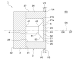
- FIG. 2 is a cross-sectional view showing a schematic configuration of the ultrasonic sensor shown in FIG. 1
- FIG. 3 is a cross-sectional view showing an outline of the operation of the ultrasonic sensor shown in FIG. 2
- FIG. 3 is a cross-sectional view showing an outline of the operation of the ultrasonic sensor shown in FIG. 2
- FIG. 10 is a perspective view showing the appearance of a vehicle equipped with an ultrasonic sensor according to a second embodiment
- 6 is a cross-sectional view showing an example of a schematic configuration of the ultrasonic sensor shown in FIG. 5;
- FIG. 5 is a cross-sectional view showing an example of a schematic configuration of the ultrasonic sensor shown in FIG. 5;
- FIG. 6 is a cross-sectional view showing another example of the schematic configuration of the ultrasonic sensor shown in FIG. 5;
- FIG. FIG. 6B is a cross-sectional view showing an overview of the operation of the ultrasonic sensor shown in FIG. 2, FIG. 6A, or FIG. 6B;
- FIG. 8 is a cross-sectional view showing a schematic configuration and an outline of operation according to a modified example of the ultrasonic sensor shown in FIG. 7;
- FIG. 8 is a cross-sectional view showing a schematic configuration and an outline of operation according to another modified example of the ultrasonic sensor shown in FIG. 7;
- FIG. 8 is a cross-sectional view showing a schematic configuration and outline of operation according to still another modification of the ultrasonic sensor shown in FIG. 7;
- FIG. 6B is a cross-sectional view showing a schematic configuration according to a modified example of the ultrasonic sensor shown in FIG. 2, FIG. 6A, or FIG. 6B;
- FIG. 7 is a cross-sectional view showing a schematic configuration according to another modified example of the ultrasonic sensor shown in FIG. 2, FIG. 6A, or FIG. 6B;
- FIG. 8 is a cross-sectional view showing a schematic configuration according to still another modification of the ultrasonic sensor shown in FIGS. 2, 6A, or 6B;
- FIG. 8 is a cross-sectional view showing a schematic configuration according to still another modification of the ultrasonic sensor shown in FIGS. 2, 6A, or 6B;
- FIG. 8 is a cross-sectional view showing a schematic configuration according to still another modification of the ultrasonic sensor shown in FIGS. 2, 6A, or 6B;
- FIG. 8 is a cross-sectional view showing a schematic configuration according to still another modification of the ultrasonic sensor shown in FIGS. 2, 6A, or 6B;
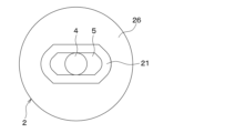
- FIG. 10 is a rear view showing a configuration example of a sensor housing and a vibration converting section in still another modified example of the ultrasonic sensor shown in FIG. 2, FIG. 6A, or FIG. 6B;
- FIG. 17 is a cross-sectional view showing an overview of the operation of the ultrasonic sensor including the sensor housing and the vibration converter shown in FIG. 16;
- FIG. 17 is a cross-sectional view showing an overview of the operation of the ultrasonic sensor including the sensor housing and the vibration converter shown in FIG. 16;
- FIG. 8 is a cross-sectional view showing a schematic configuration according to still another modification of the ultrasonic sensor shown in FIGS. 2, 6A, or 6B;
- FIG. 8 is a cross-sectional view showing a schematic configuration according to still another modification of the ultrasonic sensor shown in FIGS. 2, 6A, or 6B;
- FIG. 8 is a cross-sectional view showing a schematic configuration according to still another modification of the ultrasonic sensor shown in FIGS. 2, 6A, or 6B;
- FIG. 8 is a cross-sectional view showing a schematic configuration according to still another modification of the ultrasonic sensor shown in FIGS. 2, 6A, or 6B;
- FIG. 8 is a cross-sectional view showing a schematic configuration according to still another modification of the ultrasonic sensor shown in FIGS.
- FIG. 8 is a cross-sectional view showing a schematic configuration according to still another modification of the ultrasonic sensor shown in FIGS. 2, 6A, or 6B; It is a sectional view showing a schematic structure of an ultrasonic sensor concerning a third embodiment.
- FIG. 26 is a cross-sectional view showing a schematic configuration according to a modified example of the ultrasonic sensor shown in FIG. 25; It is a sectional view showing a schematic structure of an ultrasonic sensor concerning a fourth embodiment. It is a sectional view showing a schematic structure of an ultrasonic sensor concerning a fifth embodiment.
- FIG. 29 is a cross-sectional view showing a schematic configuration according to a modified example of the ultrasonic sensor shown in FIG. 28; FIG.
- FIG. 11 is a cross-sectional view showing a schematic configuration of an ultrasonic sensor according to a sixth embodiment
- FIG. 31 is a cross-sectional view showing a schematic configuration according to a modified example of the ultrasonic sensor shown in FIG. 30
- FIG. 31 is a cross-sectional view showing a schematic configuration according to another modified example of the ultrasonic sensor shown in FIG. 30
- 31 is a cross-sectional view showing a schematic configuration according to still another modification of the ultrasonic sensor shown in FIG. 30
- FIG. FIG. 11 is a cross-sectional view showing a schematic configuration of an ultrasonic sensor according to a seventh embodiment
- 1 is a functional block diagram showing one configuration example of an object detection device using an ultrasonic sensor according to the present disclosure
- FIG. 11 is a cross-sectional view showing a schematic configuration of an ultrasonic sensor according to a modification;
- FIG. 11 is a cross-sectional view showing a schematic configuration of an ultrasonic sensor according to a modification;
- FIG. 11 is a cross-sectional view showing a schematic configuration of an ultrasonic sensor according to a modification;
- FIG. 11 is a cross-sectional view showing a schematic configuration of an ultrasonic sensor according to a modification;
- FIG. 11 is a cross-sectional view showing a schematic configuration of an ultrasonic sensor according to a modification;
- FIG. 11 is a cross-sectional view showing a schematic configuration of an ultrasonic sensor according to a modification;
- FIG. 11 is a cross-sectional view showing a schematic configuration of an ultrasonic sensor according to a modification;
- FIG. 11 is a cross-sectional view showing a schematic configuration of an ultrasonic sensor according to a modification;
- FIG. 11 is a cross-sectional view showing a
- FIG. 11 is a cross-sectional view showing a schematic configuration of an ultrasonic sensor according to a modification;
- FIG. 11 is a cross-sectional view showing a schematic configuration of an ultrasonic sensor according to a modification;
- FIG. 11 is a cross-sectional view showing a schematic configuration of an ultrasonic sensor according to a modification;
- FIG. 11 is a cross-sectional view showing a schematic configuration of an ultrasonic sensor according to a modification;
- FIG. 11 is a cross-sectional view showing a schematic configuration of an ultrasonic sensor according to a modification;
- FIG. 11 is a cross-sectional view showing a schematic configuration of an ultrasonic sensor according to a modification;
- FIG. 11 is a cross-sectional view showing a schematic configuration of an ultrasonic sensor according to a modification;
- the ultrasonic sensor 1 is mounted on a vehicle V as a moving object, and responds to the presence of an object (for example, an obstacle) existing in the external space SG around the vehicle V. configured to generate and output a sensing signal; That is, the ultrasonic sensor 1 has a configuration as a vehicle-mounted clearance sonar to which the vehicle V is mounted.
- the vehicle V is typically a so-called four-wheel vehicle and has a box-shaped body V1.
- the vehicle body V1 includes a vehicle body panel V2 and a bumper V3, which are plate-like body parts that form an outer panel.
- the bumpers V3 are provided at the front and rear ends of the vehicle body V1.
- the ultrasonic sensor 1 is configured to be attached to the bumper V3.
- a state in which the ultrasonic sensor 1 is mounted on the vehicle V by being attached to the bumper V3 is hereinafter referred to as a “mounted state”.
- a plurality of (for example, four) ultrasonic sensors 1 are attached to the front bumper, that is, the bumper V3 on the front side of the vehicle body V1.
- a plurality of ultrasonic sensors 1 attached to the front bumper are arranged at different positions at least in the vehicle width direction.
- a plurality of (for example, four) ultrasonic sensors 1 are attached to a rear bumper, that is, a bumper V3 on the rear side of the vehicle body V1.
- the bumper V3 is provided with a mounting hole V4, which is a through hole for mounting the ultrasonic sensor 1 thereon.
- FIG. 2 shows one of the plurality of ultrasonic sensors 1 attached to the bumper V3 in its mounted state.
- the "adhesive layer” includes an adhesive layer (i.e., a synthetic resin layer formed by solidifying an adhesive) and a double-sided tape layer (i.e., by peeling the release paper from both the front and back sides of the double-sided tape). appearing adhesive layer), etc.
- the ultrasonic sensor 1 is configured to transmit and/or receive ultrasonic waves. That is, the ultrasonic sensor 1 has a transmission function of transmitting a transmission wave, which is an ultrasonic wave, to the external space SG along the directional axis DA, and/or a reception function of receiving a reflected wave of the transmission wave from an object from the external space SG. is configured to play
- the "directive axis" is a virtual straight line extending from the ultrasonic sensor 1 along the traveling direction of the transmitted wave, and serves as a reference for the directivity angle.
- the "orientation axis" may also be referred to as “orientation central axis" or “detection axis”.
- a “directivity angle” may also be referred to as a "half-value angle.”
- the ultrasonic sensor 1 receives from the external space SG received waves including reflected waves of transmitted waves from objects existing around the vehicle V, and generates and outputs a detection signal according to the reception result of the received waves. is configured as
- the axial direction includes the transmission direction DT and the reception direction DR.
- a transmission direction DT is a direction parallel to the axial direction and directed from the ultrasonic sensor 1 to the external space SG. That is, the transmission direction DT is the direction in which the transmission wave travels on the directivity axis DA.
- the receiving direction DR is the direction opposite to the transmitting direction DT, which is parallel to the axial direction and directed from the external space SG to the ultrasonic sensor 1 . That is, the receiving direction DR is the direction in which the received wave travels on the directivity axis DA.
- the “tip in the axial direction” of a component refers to the end of the component on the transmission direction DT side.
- the “proximal end in the axial direction” of a component refers to the end of the component on the receiving direction DR side.
- An arbitrary direction orthogonal to the axial direction is called an "in-plane direction”.
- the “in-plane direction” is a direction parallel to a virtual plane normal to the directivity axis DA.
- a shape of a certain component projected onto the virtual plane is called an “in-plane shape”. Note that the in-plane direction includes the "radial direction”.
- the “radial direction” is the direction in which a half-line extends when a half-line is drawn in the virtual plane starting from the point of intersection between the virtual plane and the directivity axis DA.
- the “radial direction” is the radial direction of a circle drawn in the virtual plane with the point of intersection between the virtual plane and the directivity axis DA as the center.
- the bumper V3 has a bumper outer surface V5 and a bumper inner surface V6.
- the bumper outer surface V5 is provided so as to face an external space SG, which is a space outside the vehicle V.
- the bumper inner surface V6 is the rear surface of the bumper outer surface V5.
- the mounting hole V4 is provided so as to open at the bumper outer surface V5 and the bumper inner surface V6.
- the mounting hole V4 is formed as a circular hole having the directivity axis DA as a central axis.
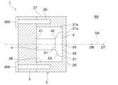
- An ultrasonic sensor 1 includes a sensor housing 2 , a fixing section 3 , a conversion element 4 and a vibration conversion section 5 .
- a specific configuration example of each part in the ultrasonic sensor 1 according to the present embodiment will be described below.
- the sensor housing 2 is formed in the shape of a bottomed cylinder having a shape in which the tip in the axial direction of the cylindrical side wall is closed with a bottom wall and the base end is open.
- the sensor housing 2 can be made of, for example, a metal material such as aluminum or an aluminum alloy, a synthetic resin material such as polypropylene, polyacetal (that is, POM) or acrylic resin, a composite material such as CFRP, or the like.
- POM is an abbreviation for Polyoxymethylene.
- CFRP is an abbreviation for Carbon Fiber Reinforced Plastics.
- the sensor housing 2 has a diaphragm 21 .
- the diaphragm 21 is formed in a plate shape having a plate thickness direction along the directivity axis DA. That is, the diaphragm 21 is formed by the bottom wall of the bottomed cylindrical sensor housing 2 that intersects the directivity axis DA.
- Diaphragm 21 has an arbitrary in-plane shape such as circular, elliptical, and polygonal.
- the diaphragm 21 has an outer surface 21a exposed to the external space SG in the mounted state, and an inner surface 21b that is the reverse side of the outer surface 21a.
- the diaphragm 21 has a flat plate shape with a constant thickness as a typical configuration example. Therefore, in this specific example, the outer surface 21 a and the inner surface 21 b are provided as a pair of main surfaces of the diaphragm 21 .
- a “principal surface” is a surface of a plate-like portion or member whose normal direction is the plate thickness direction. That is, the outer surface 21a and the inner surface 21b are provided so as to be orthogonal to the directivity axis DA.
- the present disclosure is not limited to such a configuration.
- a non-connecting portion 22 and a connecting portion 23 may be formed on the diaphragm 21 .
- the non-connecting portion 22 is a portion on the outer edge side in the radial direction of the diaphragm 21 and is a portion where the inner surface 21b of the diaphragm 21 and the vibration conversion portion 5 do not face each other.
- the connecting portion 23 is a portion inside the non-connecting portion 22 in the radial direction of the diaphragm 21, where the inner surface 21b and the vibration converting portion 5 face each other.
- the diaphragm 21 is provided so that it can be ultrasonically vibrated in such a manner that the center portion 24 in the in-plane direction moves along the directivity axis DA.
- the sensor housing 2 has a support portion 26 that supports the outer edge portion 25 of the diaphragm 21 in the in-plane direction. That is, the support portion 26 is formed by a side wall of the bottomed cylindrical sensor housing 2 surrounding the directivity axis DA.
- the diaphragm 21 has a plate thickness smaller than the dimension of the support portion 26 in the axial direction. Diaphragm 21 may be made of a softer material than support 26 .
- the outer edge portion 25 of the diaphragm 21 is coupled to the tip portion of the support portion 26 in the axial direction.
- the diaphragm 21 is provided so as to be capable of ultrasonic vibration in a primary vibration mode in which the outer edge portion 25 in the in-plane direction is a node and the center portion 24 is an antinode.
- the support portion 26 has an outer peripheral surface 27 and an inner peripheral surface 28 .
- the outer peripheral surface 27 is formed in a cylindrical shape. At least the tip portion of the outer peripheral surface 27 in the axial direction is accommodated inside the mounting hole V4 in the mounted state.
- the inner peripheral surface 28 is formed in the shape of a cylindrical inner surface facing the directivity axis DA.
- the fixing portion 3 is provided so as to close the opening on the base end side in the axial direction of the sensor housing 2 .
- the fixed part 3 can be made of a metal material, a synthetic resin material, a composite material, or the like.
- the fixing portion 3 has a fixing surface 31 and a back surface 32 .
- the fixing surface 31 is provided so as to face the inner surface 21 b of the diaphragm 21 .
- the fixing surface 31 is joined to the base end portion in the axial direction of the support portion 26 via a joining layer such as an adhesive.
- Such a bonding layer is formed with a thickness that is sufficiently small (for example, 100 ⁇ m or less or less than one-eighth of the wavelength) with respect to the wavelength of the transmission/reception wave.
- the back surface 32 is provided on the back side of the fixing surface 31 .
- the fixed portion 3 has a plate-like shape with a constant plate thickness as a typical configuration example. Therefore, in this specific example, the fixed surface 31 and the rear surface 32 are provided as a pair of main surfaces of the fixed portion 3 that intersect (that is, are orthogonal to) the directivity axis DA. However, it is clear from the description of modified examples and the like below that the present disclosure is not limited to such a configuration.
- a circuit board (not shown) electrically connected to the vibration converting section 5 is provided on the rear surface 32 side.
- the conversion element 4 and the vibration conversion section 5 are housed in a space surrounded by the sensor housing 2 and the fixing section 3 by joining the base end portion of the support section 26 in the axial direction and the fixing surface 31 .
- the conversion element 4 and the vibration conversion section 5 are arranged adjacent to each other on the directivity axis DA.
- the fixed part 3, the conversion element 4, and the vibration conversion part 5 are arranged in this order along the transmission direction DT.
- the sensor housing 2, the fixing portion 3, the conversion element 4, and the vibration conversion portion 5 constitute a so-called ultrasonic transducer as an ultrasonic speaker and/or an ultrasonic microphone.
- the conversion element 4 is composed of an electro-mechanical energy conversion element that performs the function of converting ultrasonic vibrations along the axial direction and electrical signals.
- a piezoelectric element, a monomorph type or bimorph type vibrator, a Langevin type vibrator, or the like can be used as the conversion element 4.
- a monomorph type or bimorph type vibrator has a structure in which a piezoelectric element is attached to a plate material.
- a Langevin vibrator has a configuration in which a plate-shaped piezoelectric element having a thickness direction along an axial direction is sandwiched between a pair of blocks.
- the conversion element 4 has a base end portion 41 that is one end portion in the axial direction and a tip portion 42 that is the other end portion.
- the base end portion 41 is fixed to the fixing surface 31 of the fixing portion 3 via a bonding layer such as an adhesive layer.
- a bonding layer is formed with a thickness that is sufficiently small (for example, 100 ⁇ m or less or less than one-eighth of the wavelength) with respect to the wavelength of the transmission/reception wave.
- the tip portion 42 protrudes from the fixed portion 3 toward the tip side in the axial direction, that is, in the transmission direction DT.
- the fixing portion 3 is arranged so as to be closer to the proximal end portion 41 than the distal end portion 42 of the conversion element 4 , and is provided so as to support the conversion element 4 in a fixed manner.
- the ultrasonic sensor 1 is present on the transmission direction DT side (that is, the direction from the proximal end portion 41 to the distal end portion 42) of the transducer element 4 by applying a drive signal, which is an electric signal, to the transducer element 4. It is configured to have a transmission function of transmitting a transmission wave to the external space SG.
- the ultrasonic sensor 1 is configured to perform a reception function of converting ultrasonic vibrations transmitted from the external space SG to the conversion element 4 by reception of the received wave into a reception signal that is an electric signal by the conversion element 4.
- the vibration converter 5 is provided between the diaphragm 21 and the conversion element 4 .
- the vibration conversion section 5 is connected to the tip portion 42 of the conversion element 4 so as to be able to transmit vibration.
- the vibration conversion unit 5 is connected to the diaphragm 21 so as to be able to transmit vibration. That is, the vibration conversion unit 5 has a function of converting one of ultrasonic vibration (e.g., stretching vibration along the axial direction) in the conversion element 4 and ultrasonic vibration (e.g., membrane vibration) in the diaphragm 21 to the other.
- ultrasonic vibration e.g., stretching vibration along the axial direction
- ultrasonic vibration e.g., membrane vibration
- the ultrasonic sensor 1 the ultrasonic vibration generated in the conversion element 4 by the application of the driving signal is transmitted from the conversion element 4 to the vibration plate 21 via the vibration conversion unit 5, and the vibration plate 21 ultrasonically vibrates.
- the ultrasonic sensor 1 converts the ultrasonic vibration transmitted from the diaphragm 21 excited by the reception of the received wave from the external space SG to the transducer element 4 via the vibration transducer 5 into a received signal at the transducer element 4. It is configured to perform a transforming receiving function.
- the vibration converting portion 5 has a first facing surface 51 close to the tip portion 42 of the conversion element 4 and a second facing surface 52 close to the diaphragm 21 on the back side of the first facing surface 51 .
- the first opposing surface 51 and the second opposing surface 52 are formed in a planar shape that intersects (that is, is perpendicular to) the directivity axis DA. That is, the first opposing surface 51 and the second opposing surface 52 are provided substantially parallel to each other.
- the first opposing surface 51 is bonded to the tip portion 42 of the conversion element 4 via a bonding layer such as an adhesive layer.
- the second facing surface 52 is bonded to the inner surface 21b of the connection portion 23 of the diaphragm 21 via a bonding layer such as an adhesive layer.
- a bonding layer such as an adhesive layer.
- These bonding layers are formed to have a thickness that is sufficiently small (for example, 100 ⁇ m or less or less than 1/8 of the wavelength) with respect to the wavelength of the transmitted and received waves.
- the vibration converting portion 5 is formed so that the first opposing surface 51 and the second opposing surface 52 have different areas, so that the function of converting the area of the vibration surface can be achieved. Specifically, as shown in FIG. 2 , in this specific example, the vibration converting portion 5 is formed so that the second facing surface 52 has a larger area than the first facing surface 51 . ing. For this reason, the end surface 53 provided between the first opposing surface 51 and the second opposing surface 52 is formed in a partial pyramidal surface shape having a straight generatrix whose in-plane shape increases toward the transmission direction DT. It is
- the ultrasonic sensor 1 has a configuration such that the vibration mode of the diaphragm 21 is limited to the primary vibration mode by the vibration converter 5 . Specifically, when the vibration conversion unit 5 is urged in the transmission direction DT by the conversion element 4 in the transmission function, the connection portion 23 of the diaphragm 21 can be efficiently pushed out in the transmission direction DT. It has a hardness greater than that of the diaphragm 21 .
- "Hard” as used herein means having a high density and/or a high Young's modulus. In general, the higher the density and the higher the Young's modulus, the higher the acoustic impedance.
- the vibration converter 5 is configured to behave rigidly when vibration is transmitted between the diaphragm 21 and the conversion element 4 .
- the vibration conversion unit 5 is arranged such that the second opposing surface 52 moves in parallel in the axial direction with the ultrasonic vibration of the conversion element 4 without bending (that is, without changing the in-plane shape). and is adapted to ultrasonically vibrate in a manner.
- the vibration converter 5 is configured to increase the efficiency of vibration transmission between the diaphragm 21 and the conversion element 4 .
- the vibration conversion unit 5 is made of a material having an acoustic impedance equal to or higher than the diaphragm 21 and equal to or lower than the conversion element 4 .
- the acoustic impedance of the conversion element 4 is assumed to be greater than the acoustic impedance of the diaphragm 21 .
- the vibration conversion unit 5 may be made of a metal material such as aluminum, an aluminum alloy, or a magnesium alloy, a synthetic resin material such as PBT or a glass epoxy resin, a composite material such as CFRP, or the like.
- PBT is an abbreviation for polybutylene terephthalate. If the vibration converting section 5 is made of a conductive material such as metal, it can be set to a predetermined potential (for example, a reference potential such as ground potential).
- the vibration converting portion 5 is formed so as to suppress spurious vibrations in the diaphragm 21 by having the second opposing surface 52 have an area corresponding to the area of the diaphragm 21 (that is, the inner surface 21b). That is, the vibration converting portion 5 has a shape such that the outer diameter of the second opposing surface 52 is equal to or smaller than the outer diameter of the inner surface 21b and the difference between the two is minimized.
- the width in the radial direction of the non-connecting portion 22, that is, the half value of the difference between the outer diameter of the inner surface 21b and the outer diameter of the second facing surface 52 is less than the half value of the wavelength of the transmitted and received waves. It is joined to the diaphragm 21 so that it becomes.
- a driving signal is applied to the conversion element 4 at the time of transmission.
- the transducer element 4 is ultrasonically vibrated in such a manner that it expands and contracts in the axial direction.
- the conversion element 4 is axially stretched more than the state shown in FIG.
- the base end portion 41 of the conversion element 4 is fixed to the fixed portion 3 fixedly supported by the bumper V3. Therefore, as shown in FIG. 3, the tip portion 42 of the conversion element 4 moves in the transmission direction DT by extending the conversion element 4 in the axial direction.
- the vibration conversion unit 5 is urged in the transmission direction DT by the distal end portion 42 of the conversion element 4 .
- the vibration converter 5 moves in the transmission direction DT while maintaining the planar state of the second facing surface 52 joined to the diaphragm 21 .
- the connection portion 23 of the diaphragm 21 is pushed out in the transmission direction DT while maintaining the joint surface shape with the second opposing surface 52 .
- the conversion element 4 when a negative voltage is applied, the conversion element 4 is axially compressed more than the state shown in FIG.
- the base end portion 41 of the conversion element 4 is fixed to the fixed portion 3 fixedly supported by the bumper V3. Therefore, as shown in FIG. 4, the tip portion 42 of the conversion element 4 is moved in the receiving direction DR by compressing the conversion element 4 in the axial direction.
- the vibration conversion unit 5 is urged in the reception direction DR by the tip portion 42 of the conversion element 4 .
- the vibration converter 5 moves in the receiving direction DR while maintaining the planar state of the second facing surface 52 joined to the diaphragm 21 .
- the connecting portion 23 of the diaphragm 21 is pulled in the reception direction DR while maintaining the joint surface shape with the second opposing surface 52 .
- the diaphragm 21 ultrasonically vibrates in the primary vibration mode with the outer edge portion 25 as a node and the center portion 24 as an antinode.
- the vibration mode of the diaphragm 21 is limited to the primary vibration mode by the vibration converter 5 .
- the vibration plate 21 and the support portion 26 are formed.
- substantially only the diaphragm 21 can be vibrated. This makes it possible to achieve good transmission/reception characteristics, that is, high output and/or high sensitivity.
- the vibration of the diaphragm 21 in the manner described above can be realized in a non-resonant manner. Therefore, it is possible to realize any transmission/reception frequency. That is, for example, it is possible to adjust the directivity by making the transmission frequency variable. Specifically, in the case of the primary vibration mode, it is known that the proportional relationship of directivity angle ⁇ wavelength/vibration length is approximately established. Therefore, narrow directivity is realized by increasing the frequency. On the other hand, by lowering the frequency, wide directivity is realized. Alternatively, it is possible to satisfactorily suppress the influence of changes in directivity due to temperature changes.
- the sensor housing 2 that is, the diaphragm 21 and the support portion 26, are made of a synthetic resin material whose physical properties are likely to change due to changes in temperature, it is possible to more stably achieve the desired directivity. It becomes possible.
- the conventional technology there is a trade-off between narrow directivity and broadband. That is, for example, when the outer diameter of the diaphragm 21 is increased, the directivity is narrowed and the resonance frequency is lowered. On the other hand, when the outer diameter of the diaphragm 21 is reduced, the directivity becomes wider and the resonance frequency becomes higher.
- the frequency band that can be transmitted and received depends on the electro-mechanical energy conversion characteristics of the joint between the sensor housing 2 including the diaphragm 21 and the piezoelectric element.
- the conversion element 4 as the vibration generating section and the diaphragm 21 as the directivity designing section are separated, the trade-off relationship between the directivity and the band is eliminated. , the degree of freedom in design is improved. Specifically, for example, it is possible to realize an ultrasonic sensor 1 with narrow directivity and wide band. In addition, it is clear that the ultrasonic sensor 1 with wide directivity and wide band can also be realized.
- the vibration converting portion 5 by forming the vibration converting portion 5 from a conductive material such as metal and setting it to a predetermined potential (for example, a reference potential such as ground potential), the conversion element 4 can be electromagnetically shielded satisfactorily.
- a predetermined potential for example, a reference potential such as ground potential
- EMC is an abbreviation for Electromagnetic Compatibility.
- suitable EMC countermeasures can be realized when the sensor housing 2 is integrally formed of a non-conductive material (for example, synthetic resin).
- the present embodiment employs a configuration in which the diaphragm 21 is ultrasonically vibrated in such a manner that the diaphragm 21 is pushed out and pulled in on its surface.
- desired directivity can be more stably achieved, and transmission/reception characteristics can be further improved. It should be noted that it is not always necessary to pull in, and "push or return" may be used.
- the bumper V3 is not provided with the mounting hole V4 shown in FIG. That is, the ultrasonic sensor 1 according to this embodiment can be attached to the bumper V3 without forming the attachment hole V4 in the bumper V3. In other words, the ultrasonic sensor 1 can be easily "retrofitted” to the bumper V3 of the non-equipped vehicle, which is the vehicle V once shipped from the factory without the ultrasonic sensor 1 installed.
- the ultrasonic sensor 1 according to this embodiment having such a configuration is covered from the outside by a bumper V3 that does not have a mounting hole V4 in the mounted state. Therefore, such a configuration may hereinafter be referred to as an "invisible sonar configuration.”
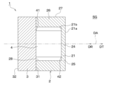
- the ultrasonic sensor 1 is configured such that a part of the bumper V3 is used as the diaphragm 21 and ultrasonic vibrations in the diaphragm 21 are used to transmit and/or receive ultrasonic waves.
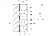
- FIG. 6A shows an example of such a configuration.
- the diaphragm 21 is constituted by a vibrating portion V7 that is part of the bumper V3.
- the vibration plate 21, that is, the vibrating portion V7 includes a damping portion V8, which is a cylindrical, ring-shaped, wall-shaped, or wall-shaped component arranged so as to surround the directional axis DA, and an adhesive layer or the like.
- the damping portion V8 is provided integrally or divided into a plurality of parts in the circumferential direction surrounding the directivity axis DA so as to surround the directivity axis DA.
- the “circumferential direction” surrounding the directivity axis DA refers to a single closed curve that surrounds the directivity axis DA when drawn on a virtual plane intersecting (that is, typically orthogonal to) the directivity axis DA. The upper point is the direction of the trajectory moving on the single closed curve.
- a “single closed curve” is a closed curve that does not intersect with itself in a three-dimensional Euclidean space, and can also be called a simple closed curve or a Jordan curve.
- a “single closed curve” includes polygons such as rectangles.
- the damping section V8 is composed of at least one component arranged to surround the directivity axis DA.
- the damping portion V8 is composed of a plurality of parts arranged in the circumferential direction, slits or gaps may be provided between adjacent parts. In this manner, the damping section V8 can be provided so as to intermittently or discontinuously surround the directivity axis DA in the circumferential direction.
- the damping portion V8 when the damping portion V8 is formed in a cylindrical shape that continuously surrounds the directivity axis DA in the circumferential direction, one or more slits or openings may be provided in the circumferential direction.
- the vibrating portion V7 is a portion inside the damping portion V8 when the bumper V3 and the damping portion V8 are joined together.
- Such a bonding layer is formed with a thickness that is sufficiently small (for example, 100 ⁇ m or less or less than one-eighth of the wavelength) with respect to the wavelength of the transmission/reception wave.
- the vibration converting portion 5, the converting element 4, and the fixing portion 3 are accommodated in the holding surface V9, which is the inner peripheral surface of the damping portion V8.
- a sensor housing 2 composed of the damping portion V8 and the fixing portion 3 is fixed to the bumper inner surface V6.
- the damping portion V8 corresponds to the support portion 26 shown in FIG. 6B and described later.
- the vibration converter 5 is connected to the diaphragm 21, which is a part of the bumper V3, so as to be able to transmit vibrations.
- the second opposing surface 52 which is the outer surface of the vibration converting portion 5, and the bumper inner surface V6 of the diaphragm 21 are arranged so that a gap, that is, an air layer, is not generated. is in contact with or joined to.
- the vibration converting section 5 also serves as an acoustic matching layer 61 shown in FIG. 6B and described later.
- the acoustic matching layer 61 is provided between the second facing surface 52, which is the outer surface of the vibration converting section 5, and the bumper inner surface V6 of the diaphragm 21 so that a gap, that is, an air layer, does not occur. may have been That is, in this case, the acoustic matching layer 61 is sandwiched between the vibration converting section 5 and the diaphragm 21 . Specifically, for example, the acoustic matching layer 61 is fixed to one of the vibration converting section 5 and the diaphragm 21 .
- the acoustic matching layer 61 interposed between the vibration converting portion 5 and the bumper V3, ie, the diaphragm 21, is provided so as to increase the vibration transmission efficiency between them.
- the acoustic matching layer 61 is configured to maximize the vibration transmission efficiency between the vibration converting section 5 and the diaphragm 21 .
- the acoustic matching layer 61 is made of a material having an acoustic impedance equal to or higher than that of the diaphragm 21 (that is, the bumper V3) and equal to or lower than the vibration converting portion 5. As shown in FIG.
- the acoustic matching layer 61 can be made of, for example, a curable synthetic resin such as epoxy resin. Alternatively, the acoustic matching layer 61 can be formed with a thickness of 50 ⁇ m or less.
- the ultrasonic sensor 1 of this embodiment having such a configuration transmits transmission waves by vibrating a portion of the bumper V3 as the diaphragm 21 during transmission. Also, during reception when the reception function is exhibited, the vibration of the diaphragm 21 excited by the received wave is converted into an electric signal to generate a received signal. And also in this embodiment, the same effect as said 1st embodiment can be show
- the configuration example shown in FIG. 6A is a simplified version of the configuration example shown in FIG. 6B described below. Specifically, in the configuration example shown in FIG. 6A, the diaphragm 21 and the bumper V3 in the sensor housing 2 provided in the configuration example shown in FIG. 6B are integrated and supported. The portion 26 and the damping portion V8 are integrated.
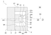
- FIG. 6B shows another example of the configuration shown in FIG. 6A.
- the ultrasonic sensor 1 according to the present embodiment is configured such that a part of the bumper V3 is used as a vibrating section V7, and ultrasonic waves are transmitted and/or received using ultrasonic vibration in the vibrating section V7.
- the vibrating portion V7 includes a damping portion V8, which is a tubular, ring-shaped, fence-shaped, or wall-shaped part surrounding the directivity axis DA, and a bonding layer such as an adhesive layer. It is formed by bonding to the bumper inner surface V6 through the V6.
- the damping portion V8 is provided integrally or divided into a plurality of parts in the circumferential direction surrounding the directivity axis DA so as to surround the directivity axis DA.
- the damping section V8 is composed of at least one component arranged to surround the directivity axis DA.
- the vibrating portion V7 is a portion inside the damping portion V8 when the bumper V3 and the damping portion V8 are joined together.
- Such a bonding layer is formed with a thickness that is sufficiently small (for example, 100 ⁇ m or less or less than one-eighth of the wavelength) with respect to the wavelength of the transmission/reception wave.
- the diaphragm 21 is connected to the vibrating portion V7 so as to be able to transmit vibration.
- an acoustic matching layer 61 is provided between the outer surface 21a of the diaphragm 21 and the inner surface V6 of the bumper in the vibrating portion V7 so as not to form a gap, ie, an air layer. That is, the acoustic matching layer 61 is sandwiched between the diaphragm 21 and the vibrating portion V7. Acoustic matching layer 61 is fixed to one of diaphragm 21 and vibrating portion V7.
- the acoustic matching layer 61 interposed between the diaphragm 21 and the bumper V3, that is, the vibrating portion V7 is provided so as to increase the vibration transmission efficiency between them. That is, the acoustic matching layer 61 is configured to maximize the efficiency of vibration transmission between the diaphragm 21 and the vibrating portion V7.
- the acoustic matching layer 61 is made of a material having an acoustic impedance equal to or higher than the vibrating portion V7 and equal to or lower than the diaphragm 21.
- the ultrasonic sensor 1 of the present embodiment having such a configuration transmits transmission waves by vibrating a portion of the bumper V3 as the vibrating portion V7 during transmission. Further, during reception when the receiving function is exhibited, the vibration of the vibrating portion V7 excited by the received wave is converted into an electric signal to generate a received signal. And also in this embodiment, the same effect as said 1st embodiment can be show
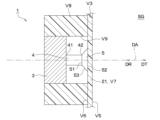
- (Structure of vibration converter) 7 to 10 show changes in directivity when the structure of the vibration converting section 5 in the ultrasonic sensor 1 is changed.
- the vibration displacement of the outer surface 21a of the diaphragm 21 and the resulting propagation of the transmission wave are indicated by dotted lines.
- Directivity is also schematically indicated by a two-dot chain line. 7 to 10, the area of the second opposing surface 52 is larger than the area of the first opposing surface 51, that is, the outer diameter of the first opposing surface 51 is larger than the second It is assumed that the outer diameter of the facing surface 52 is larger.
- the diaphragm 21 is formed in a flat plate shape having a constant thickness, like the configurations shown in FIGS. 2 and 6A.
- the first opposing surface 51 and the second opposing surface 52 are formed in a plane shape parallel to each other.
- the end face 53 is formed in a partial pyramidal surface shape having a linear generatrix and having an in-plane shape that increases toward the transmission direction DT.
- a depression occurs in the traveling wave near the center, that is, the directivity axis DA, and side lobes are generated.
- the example of FIG. 8 is obtained by changing the shape of the end face 53 of the vibration converting portion 5 in the example of FIG. 7 into a convex shape.
- the depression of the traveling wave near the center, ie, the directivity axis DA is eliminated, and a plane wave is radiated. Also, side lobes are well suppressed.
- planar first opposing surface 51 and the planar second opposing surface 52 By making the planar first opposing surface 51 and the planar second opposing surface 52 parallel to each other, the efficiency of vibration transmission from the conversion element 4 to the diaphragm 21 can be enhanced.
- these parallelism and flatness can be appropriately changed within a range in which desired directivity and transmission/reception characteristics are obtained. That is, the parallelism and flatness can vary by a predetermined degree within the range of manufacturing errors and allowable deviations. Alternatively, these parallelism and flatness may be intentionally adjusted in order to achieve desired directivity and transmission/reception characteristics.
- the example of FIG. 9 is obtained by changing the shape of the second facing surface 52 of the vibration conversion unit 5 in the example of FIG.
- the depression of the traveling wave near the center, that is, the directivity axis DA is eliminated, and a convex spherical wave is radiated in the transmission direction DT.
- the directivity is wider than in the example of FIG.
- the sidelobes are suppressed even better than in the example of FIG.
- the shape of the second facing surface 52 of the vibration converter 5 in the example of FIG. 8 is changed to a concave shape, that is, a curved surface that is concave in the transmission direction DT, contrary to the example of FIG. changed to
- a relatively large dip occurs in the traveling wave near the center, ie, the directivity axis DA.
- the sound pressure of the transmission wave in the front direction that is, around the directivity axis DA is reduced by interference.
- Such directivity makes it possible to satisfactorily detect road surface steps and ceiling protrusions.
- FIGS. 2 and 6A show configurations in which the cost of the ultrasonic sensor 1 shown in FIGS. 2 and 6A is reduced.
- the cost can be reduced.
- the vibration converter 5 can be seamlessly and integrally formed with the diaphragm 21 using the same material.
- the cost can be reduced by using a thin-plate piezoelectric element as the conversion element 4 .
- the configurations shown in FIG. 2, FIG. 6A, etc. correspond to high receiving sensitivity and narrow directivity. That is, such a configuration is preferably applied to a narrow-directivity receiving sensor.
- a “receiving sensor” refers to the ultrasonic sensor 1 that has a receiving function but does not have a transmitting function.
- the ultrasonic sensor 1 which does not have a receiving function but has a transmitting function is called a "transmitting sensor”.
- the ultrasonic sensor 1 having both a transmission function and a reception function is called a "transmission/reception integrated sensor”.
- the outer diameter of the diaphragm 21 is made small, and the second facing surface 52 of the vibration converting portion 5 has a larger area, that is, the outer diameter, than the first facing surface 51 . is formed so that the Such a configuration is preferably applied to a wide directivity receiving sensor.
- the thickness, that is, the diameter, of the support portion 26 increases toward the distal end side in the axial direction, that is, toward the transmission direction DT. It can be formed to have a large directional dimension.
- the support portion 26 has an outer peripheral surface 27 formed in a cylindrical surface shape, and an inner peripheral surface 28 having a straight generatrix and having a smaller diameter toward the transmission direction DT. It is formed in a truncated conical surface shape.
- the configuration shown in FIG. 14 is such that the outer diameter of the diaphragm 21 is increased, and the vibration converting portion 5 is arranged so that the second facing surface 52 has a smaller area, that is, the outer diameter, than the first facing surface 51 . It is formed in Such a configuration corresponds to high transmission power and narrow directivity. That is, such a configuration is preferably applied to a narrow-directivity transmission sensor.
- a tapered portion 261 may be provided at the tip portion of the support portion 26 in the axial direction in order to suppress spurious vibration.
- the tapered portion 261 is formed so that its thickness, that is, the radial dimension, increases toward the distal end side in the axial direction, that is, toward the transmission direction DT.
- the configuration shown in FIG. 15 is such that the outer diameter of the diaphragm 21 is made small, and the vibration converting portion 5 is arranged so that the second facing surface 52 has a smaller area, that is, the outer diameter, than the first facing surface 51 . It is formed in Such a configuration supports high transmission power and wide directivity. That is, such a configuration is preferably applied to a wide directivity transmission sensor. Also in such a configuration, a tapered portion 261 may be provided at the distal end portion of the support portion 26 in the axial direction in order to suppress spurious vibration.
- the diaphragm 21 has a longitudinal direction in the first in-plane direction (that is, the horizontal direction in the drawing) and a lateral direction in the second in-plane direction (that is, the vertical direction in the drawing). It has an in-plane shape (for example, an elliptical shape, an oval shape, a rectangular shape, etc.). The first in-plane direction and the second in-plane direction are in-plane directions orthogonal to each other. Further, the vibration converting portion 5 is also formed to have an in-plane shape corresponding to the in-plane shape of the diaphragm 21 .
- the support portion 26 has a rigid portion 262 and an elastic portion 263 .
- the rigid portion 262 is a portion closer to the base end than the elastic portion 263 in the axial direction of the support portion 26 and is made of a rigid material such as metal.
- the elastic portion 263 is the tip portion in the axial direction of the support portion 26 and is made of an elastomer material such as silicone rubber.
- the rigid part 262 and the elastic part 263 can be joined by a joining layer such as an adhesive.
- the elastic portion 263 may have a concave portion 264 that accommodates the outer end portion of the diaphragm 21 in the radial direction.
- a slit 265 may be provided in the sensor housing 2 as shown in FIGS.
- transmission/reception characteristics that is, transmission output and reception sensitivity can be improved.
- the slit 265 is formed at the tip of the support portion 26 in the axial direction so as to open toward the direction axis DA on the inner peripheral surface 28 of the support portion 26 .
- the slit 265 is provided at the outer end in the radial direction of the diaphragm 21 so as to open in the reception direction DR on the inner surface 21b of the diaphragm 21.
- the slit 265 may be provided along the directivity axis DA so as to open in the receiving direction DR at the base end surface of the support portion 26 in the axial direction.
- an initial load is applied in a direction that urges the conversion element 4 toward the vibration conversion portion 5.
- the bonding layer may be omitted.
- the diaphragm 21 is displaced to the position where the initial load is canceled, and then further displaced in the receiving direction DR by the momentum of the elastic energy of the diaphragm 21 . Therefore, the voltage when the negative voltage is applied can be favorably lowered. Alternatively, good driving can be achieved without applying a negative voltage.
- conversion element structure As described above, various types of electro-mechanical energy conversion elements can be used as conversion elements 4 .
- the conversion element 4 is of a type that stretches and vibrates along the axial direction for simplification of explanation.
- the present disclosure is not limited to such aspects.
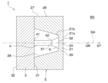
- FIG. 25 shows an example of using a plate-shaped piezoelectric element that flexures and vibrates as the conversion element 4 .
- the conversion element 4 is supported by a projecting portion 331 projecting in the transmission direction DT from the fixed surface 31 of the fixed portion 3 .
- a support projection 332 is provided on the projecting portion 331 formed in a block shape.
- the support protrusion 332 protrudes in the transmission direction DT from the distal end surface of the projecting portion 331 in the axial direction. Further, the support protrusion 332 is provided at the radially outer end of the projecting portion 331 .
- the conversion element 4 is configured as a monomorph-type piezoelectric element formed in a plate shape having a thickness direction in the axial direction.
- the conversion element 4 has a support plate 401 and a piezoelectric thin plate 402 .
- the support plate 401 is a plate-like member having a thickness direction in the axial direction, and is made of metal or the like.
- the support plate 401 is provided as a so-called doubly supported beam in which both ends in the in-plane direction are supported by the support projections 332 in a cross-sectional view.
- the piezoelectric thin plate 402 is a piezoelectric element plate formed to have substantially the same in-plane shape as the support plate 401 and is joined to the support plate 401 .
- the conversion element 4 is provided so as to ultrasonically vibrate in a mode of flexural vibration with a central portion 431 in the in-plane direction as a node or antinode. That is, the fixed portion 3 is configured to fixedly support the fixed end portion 432 that is the end portion of the conversion element 4 in the in-plane direction. According to such a configuration, the resonance design of the conversion element 4 makes it possible to obtain a high transmission output or a high reception sensitivity.
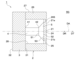
- FIG. 26 also shows an example of using a plate-shaped piezoelectric element that flexures and vibrates as the conversion element 4 .
- the projecting portion 331 is formed in a tubular shape.
- the conversion element 4 has a configuration as a monomorph type or bimorph type piezoelectric element formed in a plate shape having a thickness direction in the axial direction.
- the conversion element 4 is shown as a single plate for the sake of simplification of illustration. In the configuration shown in FIG. 26, the size of the conversion element 4 in the in-plane direction is made larger than in the configuration shown in FIG. 25 in order to further increase the output or sensitivity.
- the amount of displacement in the axial direction of the vibration converting portion 5 that is, the second opposing surface 52 is generated corresponding to the amount of deflection of the conversion element 4 . That is, the vibration due to the bending motion of the conversion element 4 is converted by the vibration conversion portion 5 into axial vibration due to the parallel movement of the second opposing surface 52 .
- the conversion element 4 provided in the transmission sensor for example, a laminated piezoelectric element, a monomorph oscillator, a bimorph oscillator, a Langevin oscillator, or the like can be preferably used.
- the conversion element 4 provided in the receiving sensor for example, a single-layer piezoelectric element, a monomorph oscillator, a bimorph oscillator, or the like can be preferably used.
- FIG. 27 shows a configuration in which the function of one conversion element 4 can be switched between a multilayer piezoelectric element and a single-layer piezoelectric element in order to avoid such a trade-off. That is, as shown in FIG. 27, the transducer element 4 includes a plurality of piezoelectric layers 441, at least one insulating layer 442, one reference electrode layer 443, one drive electrode layer 444, and at least one It has two internal reference electrode layers 445 and at least one internal drive electrode layer 446 .
- the piezoelectric layer 441 is made of a piezoelectric material such as lead zirconate titanate (that is, PZT).
- the multiple piezoelectric layers 441 are arranged in the axial direction.
- the insulating layer 442 is made of an insulating non-piezoelectric material (for example, alumina ceramics), and is arranged between two piezoelectric layers 441 adjacent in the axial direction.
- the piezoelectric layer 441 and the insulating layer 442 are formed in a layer shape or a film shape having a thickness direction in the axial direction.
- the reference electrode layer 443 is provided on the tip surface in the axial direction of the conversion element 4, that is, on the tip surface in the axial direction of the one of the plurality of piezoelectric layers 441 that is arranged closest to the tip side in the axial direction.
- the driving electrode layer 444 is provided on the axial base end surface of the conversion element 4 , that is, on the axial base end surface of the piezoelectric layer 441 that is arranged on the most axial base end side among the plurality of piezoelectric layers 441 .
- the internal reference electrode layer 445 is provided so as to be sandwiched between the insulating layer 442 and the tip surface in the axial direction of the plurality of piezoelectric layers 441 other than the one arranged on the tip end side in the axial direction.
- the internal drive electrode layer 446 is provided so as to be sandwiched between the insulating layer 442 and the axial proximal end surface of the piezoelectric layers 441 other than the one disposed closest to the proximal end in the axial direction.
- the reference electrode layer 443, the drive electrode layer 444, the internal reference electrode layer 445, and the internal drive electrode layer 446 are formed in a layer or film having a thickness direction in the axial direction using, for example, silver paste.
- the reference electrode layer 443 and internal reference electrode layer 445 are set to the reference potential.
- a high frequency drive voltage is applied between the reference electrode layer 443 and the internal drive electrode layer 446, between the internal reference electrode layer 445 and the internal drive electrode layer 446, and between the internal reference electrode layer 445 and the drive electrode layer 444.
- a high frequency drive voltage is applied between the conversion element 4 operates as a laminated piezoelectric element.
- the voltage between the reference electrode layer 443 and the internal drive electrode layer 446 provided on both sides of the one of the plurality of piezoelectric layers 441 that is arranged on the tip end side in the axial direction. Based on this, a received signal is generated.
- other internal drive electrode layers 446 and drive electrode layers 444 are set to the reference potential. Thereby, the conversion element 4 operates as a single-layer piezoelectric element.
- the function of one conversion element 4 can be achieved by the switching operation of the control circuit (not shown) electrically connected to the conversion element 4 between the stacked piezoelectric element and the single-layer piezoelectric element. Switching becomes possible. Therefore, it is possible to realize a transmitter-receiver integrated sensor capable of achieving both high transmission output and high reception sensitivity with a simple configuration.
- FIG. 28 shows a configuration in which a transmitting element 451 having a transmitting function and a receiving element 452 having a receiving function are separately provided as the conversion element 4 . That is, the conversion element 4 includes a transmission element 451 , a reception element 452 and a connecting portion 453 .
- the transmitting element 451 for example, a laminated piezoelectric element, a monomorph oscillator, a bimorph oscillator, a Langevin oscillator, or the like can be used.
- the receiving element 452 for example, a single-layer piezoelectric element, a monomorph oscillator, a bimorph oscillator, or the like can be used.
- the connecting portion 453 is sandwiched between the transmitting element 451 and the receiving element 452 .
- the transmitting element 451, the connecting portion 453, and the receiving element 452 are arranged in this order on the directional axis DA.
- the transmission element 451 is provided on the base end portion 41 side of the conversion element 4 .
- the receiving element 452 is provided on the tip portion 42 side of the conversion element 4 .
- the connecting portion 453 has a transmitting element facing surface 454 that is a main surface facing the transmitting element 451 and a receiving element facing surface 455 that is a main surface facing the receiving element 452 .
- the transmitting element facing surface 454 and the receiving element facing surface 455 are formed in planar shapes substantially orthogonal to the directivity axis DA and parallel to each other.
- the connecting portion 453 is bonded to the transmitting element 451 via a bonding layer such as an adhesive layer on the transmitting element facing surface 454 .
- the connecting portion 453 is joined to the receiving element 452 at the receiving element facing surface 455 via a bonding layer such as an adhesive layer.
- These bonding layers are formed to have a thickness that is sufficiently small (for example, 100 ⁇ m or less or less than 1/8 of the wavelength) with respect to the wavelength of the transmitted and received waves.
- the receiving element 452 is formed with a smaller area, ie, an outer diameter, than the transmitting element 451 in the plane perpendicular to the axial direction.
- the connecting portion 453 is formed in a substantially frustum shape such that the receiving element facing surface 455 has a smaller area, ie, an outer diameter, than the transmitting element facing surface 454 .
- the connecting part 453 is configured to behave rigidly when vibration is transmitted between the transmitting element 451 and the receiving element 452 , similarly to the vibration converting part 5 .
- the connecting portion 453 transmits ultrasonic waves in such a manner that the transmitting element facing surface 454 and the receiving element facing surface 455 move in parallel in the axial direction without bending in accordance with the ultrasonic vibration of the transmitting element 451 or the receiving element 452 . arranged to vibrate.
- the transmitting element 451 can be a large-diameter laminated piezoelectric element
- the receiving element 452 can be a small-diameter single-layer piezoelectric element. Become.
- a transmitter-receiver integrated sensor capable of achieving both high transmission output and high reception sensitivity.
- the transmitting element 451 and the receiving element 452 having different in-plane shapes with the coupling portion 453, vibration transmission loss between the transmitting element 451 and the receiving element 452 can be avoided.
- FIG. 28 shows a configuration for narrow directivity in which the outer diameter of the diaphragm 21 is increased. That is, such a configuration corresponds to high transmission/reception characteristics and narrow directivity.
- FIG. 29 shows a configuration for wide directivity in which the outer diameter of diaphragm 21 is reduced. That is, such a configuration corresponds to high transmission/reception characteristics and wide directivity.
- the support portion 26 in order to suppress spurious vibration, has a first side plate portion 267, a second side plate portion 268, and a stepped portion 269, as shown in FIG. It can be formed into a square shape.
- the first side plate portion 267 is a portion on the base end side in the axial direction of the support portion 26 and has a large inner diameter corresponding to the large diameter transmitting element 451 .
- the second side plate portion 268 is a portion on the tip side in the axial direction of the support portion 26 and has a small inner diameter corresponding to the small diameter receiving element 452 .
- the stepped portion 269 is provided to connect the large inner diameter of the first side plate portion 267 and the small inner diameter of the second side plate portion 268 .
- the first side plate portion 267, the second side plate portion 268, and the stepped portion 269 have the same outer diameter. That is, the support portion 26 is formed in a substantially cylindrical shape whose inner diameter changes in the axial direction.
- FIG. 3 shows a configuration in which the same effects as those of these embodiments can be obtained while omitting the vibration converting section 5 in each of the above-described embodiments shown in FIG. 2 and the like.
- the ultrasonic sensor 1 includes a sensor housing 2, a fixing portion 3, and a conversion element 4.
- the sensor housing 2 has a diaphragm 21 .
- the diaphragm 21 has a plate thickness direction along the directivity axis DA, and is capable of ultrasonically vibrating in a manner in which a central portion 24 in an in-plane direction intersecting the directivity axis DA moves along the directivity axis DA. 26.
- the conversion element 4 is provided so that the tip portion 42 contacts the inner surface 21b of the diaphragm 21 either directly or via the bonding layer. That is, the conversion element 4 is sandwiched between the fixed portion 3 and the diaphragm 21 .
- the conversion element 4 is provided so as to ultrasonically vibrate the diaphragm 21 in such a manner that it pushes out and pulls in the plane.
- the ultrasonic vibration generated in the conversion element 4 by the application of the drive signal is transmitted from the conversion element 4 to the diaphragm 21, and the diaphragm 21 is ultrasonically vibrated.
- the ultrasonic sensor 1 performs a reception function of converting ultrasonic vibrations transmitted from the diaphragm 21, which is excited by receiving ultrasonic waves from the external space SG, to the transducer element 4 into a received signal by the transducer element 4. is configured as
- the ultrasonic sensor 1 has at least a transmission function, and the conversion element 4 is arranged so as to expand and contract in the axial direction. Assume that it has a vibrating type configuration. Then, mainly, the operation when the transmission function is exhibited, that is, the operation when the ultrasonic sensor 1 transmits the transmission wave to the external space SG will be described.
- a driving signal is applied to the conversion element 4 at the time of transmission.
- the transducer element 4 is ultrasonically vibrated in such a manner that it expands and contracts in the axial direction.
- the conversion element 4 is axially stretched more than the state shown in FIG.
- the base end portion 41 of the conversion element 4 is fixed to the fixed portion 3 fixedly supported by the bumper V3. Therefore, the tip portion 42 of the conversion element 4 moves in the transmission direction DT by extending the conversion element 4 in the axial direction.
- the diaphragm 21 is urged in the transmission direction DT by the tip portion 42 of the conversion element 4 .
- the diaphragm 21 moves in the transmission direction DT while maintaining a planar state at the junction with the tip 42 of the conversion element 4 .
- the diaphragm 21 is pushed out in the transmission direction DT while maintaining the joint surface shape with the tip portion 42 of the conversion element 4 .
- the conversion element 4 when a negative voltage is applied, the conversion element 4 is axially compressed more than the state shown in FIG.
- the base end portion 41 of the conversion element 4 is fixed to the fixed portion 3 fixedly supported by the bumper V3. Therefore, the tip portion 42 of the conversion element 4 moves in the reception direction DR by compressing the conversion element 4 in the axial direction.
- the diaphragm 21 is urged in the reception direction DR by the tip portion 42 of the conversion element 4 .
- the diaphragm 21 moves in the reception direction DR while maintaining the planar state at the joint portion of the conversion element 4 with the tip portion 42 .
- the diaphragm 21 is pulled in the reception direction DR while maintaining the joint surface shape with the tip portion 42 of the conversion element 4 .
- the diaphragm 21 ultrasonically vibrates in the primary vibration mode with the outer edge portion 25 as a node and the center portion 24 as an antinode.
- the vibration mode of the diaphragm 21 is limited to the primary vibration mode. As a result, it is possible to satisfactorily suppress the collapse of the directivity due to the generation of vibration modes higher than the primary vibration mode.
- a tapered portion 261 may be provided at the tip portion in the axial direction of the support portion 26 in order to suppress spurious vibration.
- an acoustic matching layer 61 may be provided between the conversion element 4 and the diaphragm 21 .
- the acoustic matching layer 61 may be formed in the shape of a thin plate, or may be formed relatively thick.
- the conversion element 4 may comprise a transmission element 451, a reception element 452, and a connecting portion 453.
- the receiving element 452 is formed with an area smaller than that of the transmitting element 451, as in the example of FIG.
- the arrangement order of the transmitting element 451, the receiving element 452, and the connecting portion 453 is reversed. That is, the receiving element 452, the connecting portion 453, and the transmitting element 451 are arranged in this order in the transmitting direction DT.
- the transmitting element 451 which is a large-diameter laminated piezoelectric element, pushes out the diaphragm 21 from the plane, so that the diaphragm 21 vibrates in primary vibration with the outer edge portion 25 as a node and the central portion 24 as an antinode.
- Ultrasonic vibration mode The vibration mode of the diaphragm 21 is limited to the primary vibration mode. As a result, it is possible to satisfactorily suppress the collapse of the directivity due to the generation of vibration modes higher than the primary vibration mode. In addition, such ultrasonic vibration can be realized in a non-resonant manner. Therefore, it is possible to realize any transmission/reception frequency. Furthermore, changes in transmission/reception characteristics due to temperature changes can be suppressed satisfactorily. Therefore, it is possible to realize a transmitter-receiver integrated sensor capable of achieving both high transmission output and high reception sensitivity with a simple configuration.
- the ultrasonic sensor 1 includes a sensor housing 2, a fixing section 3, a conversion element 4, and a vibration conversion section 5.
- the sensor housing 2 is formed in a bottomless tubular shape without the diaphragm 21 shown in FIG. 2 and the like.
- the vibration converting portion 5 is fixed to the tip portion 42 of the conversion element 4 so as to be connected to the tip portion 42 so as to be able to transmit vibration.
- the vibration conversion section 5 has a first facing surface 51 that is close to the tip portion 42 of the conversion element 4 and a second facing surface 52 that is the rear surface of the first facing surface 51 .
- the first opposing surface 51 is bonded to the tip portion 42 of the conversion element 4 via a bonding layer such as an adhesive layer.
- the second facing surface 52 is provided so as to face the external space SG in the mounted state.
- the vibration converting portion 5 is formed so that the second facing surface 52 has a larger area than the first facing surface 51 .
- the second opposing surface 52 is formed such that its outer diameter is slightly smaller than the inner diameter of the inner peripheral surface 28 of the support portion 26 .
- a sealing material 621 is provided so as to fill the gap between the tip portion of the vibration converting portion 5 in the axial direction and the support portion 26 .
- the sealing material 621 may be made of an elastomer material such as silicone rubber so as not to hinder the reciprocating vibration of the vibration converting section 5 in the axial direction.
- the ultrasonic vibration generated by the conversion element 4 due to the application of the drive signal is transmitted from the conversion element 4 to the vibration conversion section 5, and the vibration conversion section 5 generates an ultrasonic wave.
- the ultrasonic sensor 1 has a receiving function of converting ultrasonic vibrations transmitted from the vibration conversion unit 5 to the conversion element 4 excited by reception of ultrasonic waves from the external space SG into a reception signal by the conversion element 4. configured to play.
- the vibration converting portion 5 ultrasonically vibrates in a manner of reciprocating in the axial direction while maintaining the planar state of the first opposing surface 51 and the second opposing surface 52 . Therefore, according to this configuration, it is possible to always perform transmission and reception in the primary vibration mode. Ultrasonic vibration of this mode can be realized in a non-resonant manner. Therefore, it is possible to realize any transmission/reception frequency. Also, changes in transmission/reception characteristics due to temperature changes can be well suppressed.
- the object detection device 700 includes multiple ultrasonic sensors 1 .
- the object detection device 700 also includes a transmission circuit 701 , a reception circuit 702 , a driving signal generation section 703 , a reception signal processing section 704 and a control section 705 .
- the transmission circuit 701 is electrically connected to the ultrasonic sensor 1 so as to input a drive signal to the ultrasonic sensor 1 .
- the transmission circuit 701 has a digital/analog conversion circuit and the like. That is, the transmission circuit 701 performs processing such as digital/analog conversion on the drive signal output from the drive signal generation unit 703, and applies the generated AC voltage to the conversion element 4 in the ultrasonic sensor 1.
- the reception circuit 702 performs signal processing such as amplification and analog/digital conversion on the reception signal generated by the conversion element 4 in response to the ultrasonic wave reception result in the ultrasonic sensor 1 , and outputs the reception signal processing unit 704 . is provided to output to Specifically, the receiving circuit 702 has an amplifier circuit, an analog/digital conversion circuit, and the like.
- a transmission circuit 701 and a reception circuit 702 can be provided corresponding to each of the plurality of ultrasonic sensors 1 .
- the drive signal generator 703 is provided to generate a drive signal for outputting a transmission wave of a predetermined frequency from the ultrasonic sensor 1 and input it to the transmission circuit 701 .
- the drive signal generator 703 is configured to change the frequency of the drive signal based on the control signal output from the controller 705 .
- the received signal processing unit 704 is provided to perform various signal processing such as filtering on the received signal output from the receiving circuit 702 .
- the received signal processing section 704 is provided so as to output a processed signal, which is the result of various signal processing, to the control section 705 .
- the driving signal generating section 703 and the received signal processing section 704 can be provided in common to the plurality of ultrasonic sensors 1 .
- the control unit 705 is provided in common for the plurality of ultrasonic sensors 1 .
- the control unit 705 has a configuration as an in-vehicle microcomputer including a CPU, ROM, RAM, non-volatile rewritable memory, etc. (not shown). That is, the control unit 705 reads and executes a control program stored in the ROM or non-volatile rewritable memory, thereby controlling the operation of the object detection device 700, including the transmission/reception operations of each of the plurality of ultrasonic sensors 1.
- control unit 705 is configured as Based on the signals received by each of the plurality of ultrasonic sensors 1, the control unit 705 generates a detection signal corresponding to the existence state of an object (for example, an obstacle) existing in the external space SG, and outputs the detection signal. It is configured to output to an external device.
- the control unit 705 has a parameter acquisition unit 751, a frequency adjustment unit 752, and an object measurement unit 753 as functional configurations realized on an in-vehicle microcomputer.
- the parameter acquisition unit 751 acquires parameters related to physical quantities that affect the transmission/reception operations of the ultrasonic sensor 1 .
- Such parameters include structural parameters and environmental parameters.
- Structural parameters are parameters related to the structure of the ultrasonic sensor 1 including the diaphragm 21, and include, for example, the thickness and outer diameter of the diaphragm 21, temperature characteristics of physical properties (such as Young's modulus), and the like.
- the environmental parameters are parameters related to the environment of the ultrasonic sensor 1 including the diaphragm 21, such as temperature.
- the frequency adjuster 752 adjusts the frequency of the drive signal to set the frequency of the transmission wave to a predetermined frequency. That is, the frequency adjuster 752 adjusts the frequency of the transmission wave so that the ultrasonic sensor 1 can obtain a predetermined directivity.
- the frequency adjuster 752 is also adapted to adjust or correct the drive signal frequency based on structural and/or environmental parameters. Furthermore, the frequency adjuster 752 adjusts the frequencies of the transmission waves so that the frequencies of the transmission waves of the two adjacent ultrasonic sensors 1 are different, thereby suppressing the occurrence of interference.
- the object measuring unit 753 measures the shape of an object existing around the vehicle V based on the reception result of the reflected wave of the transmitted wave by the object.
- the object detection device 700 having such a configuration, it is possible to adjust transmission/reception characteristics such as directivity, sound pressure, and sensitivity within specified values by correcting the frequency of the driving signal based on structural parameters and environmental parameters. becomes. Also, by changing the frequency according to the application and mounting position, it is possible to obtain the desired directivity.
- a configuration using a portion of the bumper V3 as the vibrating portion V7, as shown in FIGS. 5 and 6A, is very effective because it requires calibration depending on the mounting location. Furthermore, height information of the object can be acquired based on the object measurement results with different directivities.
- countermeasures against interference enable simultaneous measurement and high-frequency measurement. From this point of view, it is preferable to modulate the transmission wave. Specifically, by transmitting a transmission wave whose frequency changes over time and by detecting the correlation between the reference signal corresponding to the modulation mode of the transmission wave and the received signal, it is possible to effectively prevent interference. be. It is also preferable to use a transmission wave having at least one of frequency shift keying and phase shift keying. According to such a configuration, erroneous detection due to interference can be avoided even better. It is also possible to improve the S/N ratio and distance resolution.
- the vehicle V to which the method is applied is not limited to a four-wheeled vehicle.
- the vehicle V may be a three-wheeled vehicle, or a six-wheeled or eight-wheeled vehicle such as a freight truck.
- the type of vehicle V may be an automobile equipped only with an internal combustion engine, an electric vehicle or a fuel cell vehicle without an internal combustion engine, or a so-called hybrid vehicle.
- the shape and structure of the vehicle body V1 are also not limited to a box shape, ie, a substantially rectangular shape in a plan view.
- the mobile object to which the method is applied is not limited to the vehicle V, and may be, for example, a ship or an aircraft.
- the mounting target of the ultrasonic sensor 1 is not limited to the bumper V3.
- the ultrasonic sensor 1 may be attached to the vehicle body panel V2.
- materials constituting the vehicle body panel V2 and/or the bumper V3 to which the ultrasonic sensor 1 is attached may be FRP, CFRP, steel plates, and the like.
- FRP stands for Fiber Reinforced Plastics.
- CFRP is an abbreviation for Carbon Fiber Reinforced Plastics.
- the ultrasonic sensor 1 can be applied to input devices in human-machine interface devices such as car navigation devices and center information display devices.
- the ultrasonic sensor 1 may be attached to the interior of the vehicle, that is, the dashboard, the center console, the ceiling of the vehicle, and the like.
- the ultrasonic sensor 1 can also be used as an input device in mobile phones, personal computers, electrical appliances, machine tools, and the like.
- the ultrasonic sensor 1 can be used as a human detection sensor in automatic doors, security cameras, and the like.
- the ultrasonic sensor 1 is not limited to a transmission/reception integrated configuration. That is, for example, the ultrasonic sensor 1 may have a configuration capable of only transmitting ultrasonic waves. Alternatively, the ultrasonic sensor 1 may have only a function of receiving a transmitted wave, which is an ultrasonic wave, transmitted from another ultrasonic transmitter and reflected by a surrounding object.
- each part in the ultrasonic sensor 1 is also not limited to the above specific example.
- the in-plane shape of each portion is not limited to circular, but may be elliptical, quadrangular, hexagonal, octagonal, or the like.
- the sensor housing 2 may have a polygonal prismatic outer shape.
- the tubular component surrounding the directivity axis DA may be formed in an elliptical tubular shape or a polygonal tubular shape (for example, a square tubular shape) in addition to the cylindrical shape.
- tubular component surrounding the directivity axis DA may be replaced by a plurality of components having arbitrary shapes such as columnar, block-shaped, cone-shaped, wall-shaped, etc., arranged around the directivity axis DA.
- arbitrary shapes such as columnar, block-shaped, cone-shaped, wall-shaped, etc.
- FIG. 36 shows a case where the damping portion V8 is formed in a cylindrical shape or a circular ring shape.
- FIG. 37 shows a case where the vibration damping portion V8 is formed in a square tubular shape.
- the in-plane shape of the damping portion V8 is not limited to these examples, and may be, for example, an elliptical tubular shape or a polygonal tubular shape (for example, a hexagonal tubular shape).
- FIG. 38 shows a case where the damping portion V8 shown in FIG. 37 is divided into a plurality of parts in the circumferential direction.
- the manner in which the damping portion V8 is divided is not limited to the manner shown in FIG.
- the cylindrical or circular ring-shaped damping portion V8 shown in FIG. 36 can also be divided into a plurality of parts in the circumferential direction.
- the shape of one vibration damping portion V8 is not particularly limited. It can be formed in any shape such as a shape, a polygonal cylindrical shape, a truncated cone shape, a truncated polygonal pyramid shape, and the like.
- FIG. 39 shows an example in which the damping portion V8 is joined to the bumper V3 via the joining layer 801 in the configuration shown in FIG. 6A.
- the bonding layer 801 is formed of an adhesive layer, a double-sided tape layer, or the like.
- FIG. 40 shows an example in which the damping portion V8 is integrally formed with the bumper V3 without using such a bonding layer 801.
- FIG. 41 shows an example in which an acoustic matching layer 61 is provided between the vibration converter 5 and the diaphragm 21, ie, the bumper V3 in the configuration shown in FIG. FIG.
- FIG. 42 shows an example in which an acoustic matching layer 61 is provided between the vibration converter 5 and the diaphragm 21, ie, the bumper V3 in the configuration shown in FIG. Also in these examples, the same effect as the configuration shown in FIG. 6A can be achieved.
- FIG. 43A and 43B are diagrams for supplementary explanation of the bonding layer and fixture, which are appropriately omitted in the explanation of the configuration shown in FIG. 6A in the first embodiment.
- the fixing portion 3 is fixed to the vibration damping portion V8 at a first fixing portion F1 facing the holding surface V9, which is the inner peripheral surface of the vibration damping portion V8.
- a screw or fitting structure (for example, an engaging structure between an engaging hole and an engaging pawl) or the like can be used at the first fixing point F1.
- the damping portion V8 is fixed to the bumper V3 at a second fixing point F2 facing the bumper inner surface V6.
- joining means such as welding, or fixing means using fasteners such as screws can be used.
- a bonding means such as an adhesive or an acoustic matching material for filling the gap may be used for the third fixing point F3 where the conversion element 4 is fixed to the fixing portion 3 .
- a joining means such as an adhesive or an acoustic matching material for filling the gap may be used.
- FIG. 44 shows an example in which the fixing mode between the fixing portion 3 and the damping portion V8 in FIG. 43 is changed. That is, in FIG. 44, the fixing surface 31 of the fixing portion 3 and the base end surface of the damping portion V8 in the axial direction are joined and fixed.
- FIG. 45 shows a modification of the configuration shown in FIGS. 1 and 2 in which the bumper V3 is provided with the mounting holes V4.
- the synthetic resin diaphragm portion 901 is accommodated in the mounting hole V4 so that its outer surface is substantially flush with the bumper outer surface V5.
- the vibration plate portion 901 can be ultrasonically vibrated by a damping support portion 902 provided integrally or divided into a plurality of parts in the circumferential direction so as to surround the directivity axis DA at the outer portion in the in-plane direction. Supported. That is, the damping support portion 902 has the same configuration and function as the support portion 26 shown in FIG. 2 and the like or the damping portion V8 shown in FIG. 6A and the like.
- a sensor holding portion for fixing the ultrasonic sensor 1 to the bumper V3 for keeping the diaphragm portion 901 flush with the bumper outer surface V5 is not shown.
- the damping support portion 902 has a distal end surface 903 and a proximal end surface 904 in the axial direction. A distal end surface 903 and a proximal end surface 904 are formed in a planar shape perpendicular to the axial direction.
- the damping support portion 902 is joined to the diaphragm portion 901 via the joining layer 801 at the distal end surface 903 .
- the fixed portion 3 is fixed to the damping support portion 902 at an inner wall surface 905 which is a side surface of the damping support portion 902 and faces the directional axis DA.
- FIG. 46 shows an example in which the diaphragm portion 901 and the damping support portion 902 are integrally formed without using the bonding layer 801 in the structure shown in FIG.
- FIG. 47 shows an example in which an acoustic matching layer 61 is provided between the vibration converting section 5 and the diaphragm section 901 in the configuration shown in FIG.
- FIG. 48 shows an example in which an acoustic matching layer 61 is provided between the vibration converting section 5 and the diaphragm section 901 in the configuration shown in FIG.
- FIGS. 1 to 48 show a simplified device configuration in order to briefly describe the contents of the present disclosure. Therefore, the detailed configuration when the present disclosure is actually realized as a specific product does not necessarily match the configuration shown in FIGS. 1 to 48. FIG. That is, when the present disclosure is actually realized as a specific product, the details of the specific configuration of each part of the ultrasonic sensor 1 may differ from the configuration shown in FIGS. 1 to 48. FIG.
- the plurality of constituent elements that are seamlessly and integrally formed may be formed by bonding separate members together.
- a plurality of constituent elements that are formed by bonding separate members together may be formed seamlessly and integrally with each other.
- the plurality of components made of the same material may be made of different materials.
- a plurality of components made of different materials may be made of the same material.
Abstract
An ultrasonic sensor (1) mounted to a moving body (V) comprises a fixing unit (3) and a conversion element (4). The conversion element has a proximal-end part (41), which is one end part in an axial direction following a directional axis (DA), and a distal-end part (42), which is the other end part, the conversion element performing a function for converting between ultrasonic vibration and an electric signal. The fixing unit is provided so as to be closer to the proximal-end part than is the distal-end part of the conversion element and fixedly supports the conversion element. The ultrasonic sensor has a transmission function and/or a reception function. With the transmission function, a drive signal is applied to the conversion element, whereby an ultrasonic wave is transmitted in a transmission direction oriented toward the distal-end part from the proximal-end part rather than the conversion element. With the reception function, ultrasonic vibration that has reached the conversion element from an external space is converted to a received signal by the conversion element.
Description
本出願は、2021年12月7日に出願された日本特許出願番号2021-198458号に基づくもので、ここにその記載内容が参照により組み入れられる。
This application is based on Japanese Patent Application No. 2021-198458 filed on December 7, 2021, the contents of which are incorporated herein by reference.
本開示は、移動体に搭載される超音波センサ、および、かかる超音波センサを備えた物体検知装置に関する。
The present disclosure relates to an ultrasonic sensor mounted on a mobile object and an object detection device equipped with such an ultrasonic sensor.
超音波センサを用いて車両等の移動体の周辺の障害物を検知する技術が、従来種々開示されている。この種の超音波センサにおいて、所定の指向性が設定されることがある。具体的には、例えば、超音波センサを車両に用いた場合、路面や路面上の駐車用縁石は、障害物として検知したり警告したりしないことが望ましい。よって、この場合、水平方向における超音波の送受波範囲が広い一方で上下方向における超音波の送受波範囲が狭くなるような指向性、すなわち、水平方向の指向性に対して上下方向の指向性を絞ることが好適である。
Various techniques for detecting obstacles around moving bodies such as vehicles using ultrasonic sensors have been disclosed in the past. A predetermined directivity is sometimes set in this type of ultrasonic sensor. Specifically, for example, when an ultrasonic sensor is used in a vehicle, it is desirable not to detect a road surface or a parking curb on the road surface as an obstacle or issue a warning. Therefore, in this case, the directivity is such that the ultrasonic wave transmission/reception range is wide in the horizontal direction, while the ultrasonic wave transmission/reception range is narrow in the vertical direction. is preferably narrowed down.
この点、特許文献1に記載の超音波センサは、センサ筐体と、圧電振動子とを備えている。センサ筐体は、横断面形状がほぼ円形であり、その内部は中空部が形成され、一面が開口されている。圧電振動子は、センサ筐体の底面上の中心位置に接着剤等により固着されている。振動面は、圧電振動子を固着したセンサ筐体の底面の一部で与えられる。センサ筐体の開口側は、その左右が円弧状に切り落とされて、横断面形状が小判状の外形となっている。また、中空部は、センサ筐体の開口側の小判状の外形線に沿う形で形成され、その横断面形状が同様に小判状となっている。これにより、センサ筐体の底面の一部で与えられる超音波センサの振動面が、センサ筐体の開口側の外形線に沿った形で形成される。また、センサ筐体の開口側の外形線が曲率を有し、振動面の外形線がこれと同一の曲率を有する。また、搭載車両の路面垂直方向に寄与する側の振動面の外形線が、センサ筐体の振動面側の外形線の曲率と同一の曲率を有する。また、搭載車両の路面垂直方向に寄与する側の振動面の最も薄い部分の外形線が、センサ筐体の振動面側の外形線に沿った形で形成され、振動面の最も薄い部分の外形線とセンサ筐体の振動面側の外形線とが同一の曲率を有する。これにより、超音波の指向性を狭くすることが可能となる。
In this respect, the ultrasonic sensor described in Patent Document 1 includes a sensor housing and a piezoelectric transducer. The sensor housing has a substantially circular cross-sectional shape, has a hollow portion formed therein, and is open on one side. The piezoelectric vibrator is fixed to the center position on the bottom surface of the sensor housing with an adhesive or the like. A vibrating surface is provided by a portion of the bottom surface of the sensor housing to which the piezoelectric vibrator is fixed. The left and right sides of the opening side of the sensor housing are cut off in an arc shape to form an oval cross-sectional shape. Further, the hollow portion is formed in a shape along the outline of the oval shape on the opening side of the sensor housing, and its cross-sectional shape is similarly oval. As a result, the vibration surface of the ultrasonic sensor provided by a part of the bottom surface of the sensor housing is formed along the outline of the opening side of the sensor housing. Further, the outline of the opening side of the sensor housing has a curvature, and the outline of the vibration surface has the same curvature. Further, the outline of the vibration surface on the side that contributes to the direction perpendicular to the road surface of the mounted vehicle has the same curvature as the outline of the sensor housing on the vibration surface side. In addition, the outline of the thinnest part of the vibration surface on the side that contributes to the direction perpendicular to the road surface of the mounted vehicle is formed along the outline of the vibration surface side of the sensor housing, and the outline of the thinnest part of the vibration surface The line and the contour line on the vibrating surface side of the sensor housing have the same curvature. This makes it possible to narrow the directivity of the ultrasonic waves.
この種の超音波センサにおいて、所望の指向性をより安定的に実現したり、送受信特性をよりいっそう向上したりする試みがなされている。具体的には、例えば、特許文献1に記載の超音波センサにおいては、圧電振動子と振動面との接合構造によって決まる共振周波数以外の振動周波数では、極端に効率が低下する。よって、かかる構成においては、広帯域化が困難である。また、振動周波数の変化により、振動モードが変化する。さらに、温度変化によっても、振動モードが変化する。振動モードが変化すると、指向性も変化する。
本開示は、上記に例示した事情等に鑑みてなされたものである。すなわち、本開示は、例えば、超音波センサにおいて、所望の指向性をより安定的に実現したり、送受信特性をよりいっそう向上したりすることが可能な構成を提供するものである。 In this type of ultrasonic sensor, attempts have been made to more stably achieve desired directivity and to further improve transmission/reception characteristics. Specifically, for example, in the ultrasonic sensor described inPatent Literature 1, the efficiency drops extremely at vibration frequencies other than the resonance frequency determined by the bonding structure between the piezoelectric vibrator and the vibration surface. Therefore, in such a configuration, it is difficult to widen the band. Also, the vibration mode changes due to the change in the vibration frequency. Furthermore, the vibration mode also changes due to temperature changes. If the vibration mode changes, the directivity also changes.
The present disclosure has been made in view of the circumstances and the like exemplified above. That is, the present disclosure provides, for example, an ultrasonic sensor with a configuration capable of more stably realizing desired directivity and further improving transmission/reception characteristics.
本開示は、上記に例示した事情等に鑑みてなされたものである。すなわち、本開示は、例えば、超音波センサにおいて、所望の指向性をより安定的に実現したり、送受信特性をよりいっそう向上したりすることが可能な構成を提供するものである。 In this type of ultrasonic sensor, attempts have been made to more stably achieve desired directivity and to further improve transmission/reception characteristics. Specifically, for example, in the ultrasonic sensor described in
The present disclosure has been made in view of the circumstances and the like exemplified above. That is, the present disclosure provides, for example, an ultrasonic sensor with a configuration capable of more stably realizing desired directivity and further improving transmission/reception characteristics.
本開示の1つの観点によれば、超音波センサは、
指向軸に沿った軸方向における一端部である基端部と他端部である先端部とを有し、超音波振動と電気信号との変換機能を奏する、変換素子と、
前記変換素子における前記先端部よりも前記基端部に近接するように設けられ、前記変換素子を固定的に支持する、固定部と、
を備え、
前記変換素子に前記電気信号である駆動信号が印加されることで、前記変換素子よりも前記基端部から前記先端部に向かう送信方向に存在する外部空間に超音波である送信波を送信する送信機能
および/または
前記外部空間から前記変換素子に伝達した超音波振動を前記変換素子にて前記電気信号である受信信号に変換する受信機能
を奏するように構成されている。 According to one aspect of the present disclosure, an ultrasonic sensor comprises:
a conversion element having a base end as one end and a tip end as the other end in an axial direction along the directional axis, and performing a function of converting ultrasonic vibrations and electric signals;
a fixing part provided closer to the proximal end than the distal end of the conversion element and fixedly supporting the conversion element;
with
By applying the drive signal, which is the electric signal, to the conversion element, a transmission wave, which is an ultrasonic wave, is transmitted to an external space existing in a transmission direction from the proximal end to the distal end of the conversion element. A transmission function and/or a reception function of converting ultrasonic vibration transmitted from the external space to the conversion element into a reception signal, which is the electric signal, by the conversion element.
なお、出願書類中の各欄において、各要素に括弧付きの参照符号が付されている場合がある。この場合、参照符号は、同要素と後述する実施形態に記載の具体的構成との対応関係の単なる一例を示すものであるにすぎない。よって、本開示は、参照符号の記載によって、何ら限定されるものではない。
In addition, in each column of the application documents, each element may be given a reference sign with parentheses. In this case, the reference numerals merely indicate an example of the corresponding relationship between the same element and the specific configuration described in the embodiment described later. Therefore, the present disclosure is not limited in any way by the description of the reference numerals.
(第一実施形態:車載構造)
以下、図1および図2を参照しつつ、第一実施形態に係る超音波センサ1の概略構成について説明する。まず図1を参照すると、超音波センサ1は、移動体としての車両Vに搭載されることで、かかる車両Vの周囲の外部空間SGに存在する物体(例えば障害物)の存在状態に対応する検知信号を生成および出力するように構成されている。すなわち、超音波センサ1は、車両Vを取付対象とする車載型のクリアランスソナーとしての構成を有している。 (First embodiment: in-vehicle structure)
Hereinafter, a schematic configuration of theultrasonic sensor 1 according to the first embodiment will be described with reference to FIGS. 1 and 2. FIG. First, referring to FIG. 1, the ultrasonic sensor 1 is mounted on a vehicle V as a moving object, and responds to the presence of an object (for example, an obstacle) existing in the external space SG around the vehicle V. configured to generate and output a sensing signal; That is, the ultrasonic sensor 1 has a configuration as a vehicle-mounted clearance sonar to which the vehicle V is mounted.
以下、図1および図2を参照しつつ、第一実施形態に係る超音波センサ1の概略構成について説明する。まず図1を参照すると、超音波センサ1は、移動体としての車両Vに搭載されることで、かかる車両Vの周囲の外部空間SGに存在する物体(例えば障害物)の存在状態に対応する検知信号を生成および出力するように構成されている。すなわち、超音波センサ1は、車両Vを取付対象とする車載型のクリアランスソナーとしての構成を有している。 (First embodiment: in-vehicle structure)
Hereinafter, a schematic configuration of the
車両Vは、典型的には、いわゆる四輪自動車であって、箱状の車体V1を備えている。車体V1は、外板を構成する板状のボディ部品である、車体パネルV2およびバンパーV3を備えている。バンパーV3は、車体V1の前端部および後端部のそれぞれに設けられている。本実施形態においては、超音波センサ1は、バンパーV3に取り付けられるように構成されている。超音波センサ1がバンパーV3に取り付けられることで車両Vに搭載された状態を、以下「搭載状態」と称する。
The vehicle V is typically a so-called four-wheel vehicle and has a box-shaped body V1. The vehicle body V1 includes a vehicle body panel V2 and a bumper V3, which are plate-like body parts that form an outer panel. The bumpers V3 are provided at the front and rear ends of the vehicle body V1. In this embodiment, the ultrasonic sensor 1 is configured to be attached to the bumper V3. A state in which the ultrasonic sensor 1 is mounted on the vehicle V by being attached to the bumper V3 is hereinafter referred to as a “mounted state”.
具体的には、搭載状態にて、フロントバンパーすなわち車体V1における前面側のバンパーV3には、複数(例えば4つ)の超音波センサ1が取り付けられている。フロントバンパーに取り付けられた複数の超音波センサ1は、それぞれ、少なくとも車幅方向について異なる位置に配置されている。同様に、搭載状態にて、リアバンパーすなわち車体V1における後面側のバンパーV3には、複数(例えば4つ)の超音波センサ1が取り付けられている。本実施形態においては、バンパーV3には、超音波センサ1の取り付け用の貫通孔である取付孔V4が設けられている。
Specifically, in the mounted state, a plurality of (for example, four) ultrasonic sensors 1 are attached to the front bumper, that is, the bumper V3 on the front side of the vehicle body V1. A plurality of ultrasonic sensors 1 attached to the front bumper are arranged at different positions at least in the vehicle width direction. Similarly, in the mounted state, a plurality of (for example, four) ultrasonic sensors 1 are attached to a rear bumper, that is, a bumper V3 on the rear side of the vehicle body V1. In this embodiment, the bumper V3 is provided with a mounting hole V4, which is a through hole for mounting the ultrasonic sensor 1 thereon.
図2は、バンパーV3に取り付けられた複数の超音波センサ1のうちの1つを、搭載状態にて示している。なお、図示の簡略化のため、図2において、互いに接合状態にある隣接構成要素同士を固定的に結合するための、接合層(例えば接着剤層等の接着層や溶着層等)あるいは固定具(例えばボルト、テープ等)は、特段の言及なき限り、図示が省略されているものとする。ここで、「接着層」は、接着剤層(すなわち接着剤を固化することで形成された合成樹脂層)の他に、両面テープ層(すなわち両面テープにおける表裏両面から剥離紙を剥離することで出現する粘着層)等を含む。
FIG. 2 shows one of the plurality of ultrasonic sensors 1 attached to the bumper V3 in its mounted state. For the sake of simplification of illustration, in FIG. (For example, bolts, tapes, etc.) are omitted unless otherwise specified. Here, the "adhesive layer" includes an adhesive layer (i.e., a synthetic resin layer formed by solidifying an adhesive) and a double-sided tape layer (i.e., by peeling the release paper from both the front and back sides of the double-sided tape). appearing adhesive layer), etc.
図2を参照すると、超音波センサ1は、超音波を送信および/または受信可能に構成されている。すなわち、超音波センサ1は、超音波である送信波を指向軸DAに沿って外部空間SGに送信する送信機能、および/または、送信波の物体による反射波を外部空間SGから受信する受信機能を奏するように構成されている。「指向軸」とは、超音波センサ1から送信波の進行方向に沿って延びる仮想直線であって、指向角の基準となるものである。「指向軸」は「指向中心軸」あるいは「検出軸」とも称され得る。「指向角」は「半値角」とも称され得る。また、超音波センサ1は、車両Vの周囲に存在する物体による送信波の反射波を含む受信波を外部空間SGから受信して、受信波の受信結果に応じた検知信号を生成および出力するように構成されている。
Referring to FIG. 2, the ultrasonic sensor 1 is configured to transmit and/or receive ultrasonic waves. That is, the ultrasonic sensor 1 has a transmission function of transmitting a transmission wave, which is an ultrasonic wave, to the external space SG along the directional axis DA, and/or a reception function of receiving a reflected wave of the transmission wave from an object from the external space SG. is configured to play The "directive axis" is a virtual straight line extending from the ultrasonic sensor 1 along the traveling direction of the transmitted wave, and serves as a reference for the directivity angle. The "orientation axis" may also be referred to as "orientation central axis" or "detection axis". A "directivity angle" may also be referred to as a "half-value angle." In addition, the ultrasonic sensor 1 receives from the external space SG received waves including reflected waves of transmitted waves from objects existing around the vehicle V, and generates and outputs a detection signal according to the reception result of the received waves. is configured as
ここで、送信波の進行方向に沿った方向、具体的には、指向軸DAと平行な方向を、「軸方向」と称する。より詳細には、軸方向は、送信方向DTと受信方向DRとを含む。送信方向DTは、軸方向と平行で、且つ、超音波センサ1から外部空間SGに向かう方向である。すなわち、送信方向DTは、指向軸DA上にて、送信波が進行する方向である。一方、受信方向DRは、送信方向DTとは反対に、軸方向と平行で、且つ、外部空間SGから超音波センサ1に向かう方向である。すなわち、受信方向DRは、指向軸DA上にて、受信波が進行する方向である。また、或る構成要素の「軸方向における先端」は、当該構成要素の送信方向DT側における端をいうものとする。これに対し、或る構成要素の「軸方向における基端」は、当該構成要素の、受信方向DR側における端をいうものとする。また、軸方向と直交する任意の方向を「面内方向」と称する。「面内方向」は、指向軸DAを法線とする仮想平面と平行な方向である。また、或る構成要素の、当該仮想平面に投影した形状を、「面内形状」と称する。なお、面内方向は、「径方向」を含む。「径方向」は、上記の仮想平面と指向軸DAとの交点を起点として当該仮想平面内に半直線を描いた場合に、当該半直線が延びる方向である。換言すれば、「径方向」は、上記の仮想平面と指向軸DAとの交点を中心として当該仮想平面内に円を描いた場合の、当該円の半径方向である。
Here, the direction along the traveling direction of the transmission wave, specifically, the direction parallel to the directivity axis DA is referred to as the "axial direction". More specifically, the axial direction includes the transmission direction DT and the reception direction DR. A transmission direction DT is a direction parallel to the axial direction and directed from the ultrasonic sensor 1 to the external space SG. That is, the transmission direction DT is the direction in which the transmission wave travels on the directivity axis DA. On the other hand, the receiving direction DR is the direction opposite to the transmitting direction DT, which is parallel to the axial direction and directed from the external space SG to the ultrasonic sensor 1 . That is, the receiving direction DR is the direction in which the received wave travels on the directivity axis DA. Also, the “tip in the axial direction” of a component refers to the end of the component on the transmission direction DT side. On the other hand, the "proximal end in the axial direction" of a component refers to the end of the component on the receiving direction DR side. An arbitrary direction orthogonal to the axial direction is called an "in-plane direction". The “in-plane direction” is a direction parallel to a virtual plane normal to the directivity axis DA. Also, a shape of a certain component projected onto the virtual plane is called an “in-plane shape”. Note that the in-plane direction includes the "radial direction". The “radial direction” is the direction in which a half-line extends when a half-line is drawn in the virtual plane starting from the point of intersection between the virtual plane and the directivity axis DA. In other words, the “radial direction” is the radial direction of a circle drawn in the virtual plane with the point of intersection between the virtual plane and the directivity axis DA as the center.
図2を参照すると、バンパーV3は、バンパー外表面V5とバンパー内表面V6とを有している。バンパー外表面V5は、車両Vの外側の空間である外部空間SGに面するように設けられている。バンパー内表面V6は、バンパー外表面V5の裏面である。取付孔V4は、バンパー外表面V5およびバンパー内表面V6にて開口するように設けられている。取付孔V4は、指向軸DAを中心軸とする円孔として形成されている。
Referring to FIG. 2, the bumper V3 has a bumper outer surface V5 and a bumper inner surface V6. The bumper outer surface V5 is provided so as to face an external space SG, which is a space outside the vehicle V. As shown in FIG. The bumper inner surface V6 is the rear surface of the bumper outer surface V5. The mounting hole V4 is provided so as to open at the bumper outer surface V5 and the bumper inner surface V6. The mounting hole V4 is formed as a circular hole having the directivity axis DA as a central axis.
(第一実施形態:センサ構造)
本実施形態に係る超音波センサ1は、センサ筐体2と、固定部3と、変換素子4と、振動変換部5とを備えている。以下、本実施形態に係る超音波センサ1における各部の具体的構成例について説明する。 (First embodiment: sensor structure)
Anultrasonic sensor 1 according to this embodiment includes a sensor housing 2 , a fixing section 3 , a conversion element 4 and a vibration conversion section 5 . A specific configuration example of each part in the ultrasonic sensor 1 according to the present embodiment will be described below.
本実施形態に係る超音波センサ1は、センサ筐体2と、固定部3と、変換素子4と、振動変換部5とを備えている。以下、本実施形態に係る超音波センサ1における各部の具体的構成例について説明する。 (First embodiment: sensor structure)
An
センサ筐体2は、筒状の側壁の軸方向における先端を底壁で閉塞する一方で基端を開放した形状を有する、有底筒状に形成されている。センサ筐体2は、例えば、アルミニウムやアルミニウム合金等の金属材料、ポリプロピレンやポリアセタール(すなわちPOM)やアクリル樹脂等の合成樹脂材料、CFRP等の複合材料、等によって構成され得る。POMはPolyoxymethyleneの略である。CFRPはCarbon Fiber Reinforced Plasticsの略である。
The sensor housing 2 is formed in the shape of a bottomed cylinder having a shape in which the tip in the axial direction of the cylindrical side wall is closed with a bottom wall and the base end is open. The sensor housing 2 can be made of, for example, a metal material such as aluminum or an aluminum alloy, a synthetic resin material such as polypropylene, polyacetal (that is, POM) or acrylic resin, a composite material such as CFRP, or the like. POM is an abbreviation for Polyoxymethylene. CFRP is an abbreviation for Carbon Fiber Reinforced Plastics.
(振動板)
本実施形態においては、センサ筐体2は、振動板21を有している。振動板21は、指向軸DAに沿った板厚方向を有する板状に形成されている。すなわち、振動板21は、有底筒状のセンサ筐体2における、指向軸DAと交差する底壁により形成されている。振動板21は、円形、楕円形、多角形、等の、任意の面内形状を有している。振動板21は、搭載状態にて外部空間SGに露出する外表面21aと、外表面21aの裏面である内表面21bとを有している。なお、図2においては、本開示の内容を簡略に説明するため、振動板21は、典型的な構成例として、一定の板厚を有する平板状の形状を有しているものとする。よって、本具体例においては、外表面21aおよび内表面21bは、振動板21における一対の主面として設けられている。「主面」とは、板状の部分あるいは部材における、板厚方向を法線方向とする表面である。すなわち、外表面21aおよび内表面21bは、指向軸DAと直交するように設けられている。しかしながら、本開示がこのような構成に限定されないことは、後述の変形例等の記載からも明らかである。 (diaphragm)
In this embodiment, thesensor housing 2 has a diaphragm 21 . The diaphragm 21 is formed in a plate shape having a plate thickness direction along the directivity axis DA. That is, the diaphragm 21 is formed by the bottom wall of the bottomed cylindrical sensor housing 2 that intersects the directivity axis DA. Diaphragm 21 has an arbitrary in-plane shape such as circular, elliptical, and polygonal. The diaphragm 21 has an outer surface 21a exposed to the external space SG in the mounted state, and an inner surface 21b that is the reverse side of the outer surface 21a. In addition, in FIG. 2, in order to simply explain the contents of the present disclosure, the diaphragm 21 has a flat plate shape with a constant thickness as a typical configuration example. Therefore, in this specific example, the outer surface 21 a and the inner surface 21 b are provided as a pair of main surfaces of the diaphragm 21 . A “principal surface” is a surface of a plate-like portion or member whose normal direction is the plate thickness direction. That is, the outer surface 21a and the inner surface 21b are provided so as to be orthogonal to the directivity axis DA. However, it is clear from the description of modified examples and the like below that the present disclosure is not limited to such a configuration.
本実施形態においては、センサ筐体2は、振動板21を有している。振動板21は、指向軸DAに沿った板厚方向を有する板状に形成されている。すなわち、振動板21は、有底筒状のセンサ筐体2における、指向軸DAと交差する底壁により形成されている。振動板21は、円形、楕円形、多角形、等の、任意の面内形状を有している。振動板21は、搭載状態にて外部空間SGに露出する外表面21aと、外表面21aの裏面である内表面21bとを有している。なお、図2においては、本開示の内容を簡略に説明するため、振動板21は、典型的な構成例として、一定の板厚を有する平板状の形状を有しているものとする。よって、本具体例においては、外表面21aおよび内表面21bは、振動板21における一対の主面として設けられている。「主面」とは、板状の部分あるいは部材における、板厚方向を法線方向とする表面である。すなわち、外表面21aおよび内表面21bは、指向軸DAと直交するように設けられている。しかしながら、本開示がこのような構成に限定されないことは、後述の変形例等の記載からも明らかである。 (diaphragm)
In this embodiment, the
振動板21には、非接続部22と接続部23とが形成され得る。非接続部22は、振動板21の径方向における外縁側の部分であって、振動板21の内表面21bと振動変換部5とが対向しない部分である。これに対し、接続部23は、内表面21bと振動変換部5とが対向する、振動板21の径方向における非接続部22よりも内側の部分である。
A non-connecting portion 22 and a connecting portion 23 may be formed on the diaphragm 21 . The non-connecting portion 22 is a portion on the outer edge side in the radial direction of the diaphragm 21 and is a portion where the inner surface 21b of the diaphragm 21 and the vibration conversion portion 5 do not face each other. On the other hand, the connecting portion 23 is a portion inside the non-connecting portion 22 in the radial direction of the diaphragm 21, where the inner surface 21b and the vibration converting portion 5 face each other.
振動板21は、面内方向における中心部24が指向軸DAに沿って移動する態様で超音波振動可能に設けられている。具体的には、センサ筐体2は、振動板21の面内方向における外縁部25を支持する支持部26を有している。すなわち、支持部26は、有底筒状のセンサ筐体2における、指向軸DAを囲む側壁により形成されている。振動板21は、支持部26の軸方向における寸法よりも小さな板厚を有している。振動板21は、支持部26よりも柔らかい材料で形成され得る。振動板21の外縁部25は、支持部26の軸方向における先端部と結合されている。なお、振動板21と支持部26とが同一材料によって形成される場合、センサ筐体2は、継ぎ目なく一体に成形され得るが、後述するように、本開示は、かかる態様に限定されない。そして、振動板21は、面内方向における外縁部25を節とし且つ中心部24を腹とする一次振動モードで超音波振動可能に設けられている。支持部26は、外周面27と内周面28とを有している。外周面27は、円柱面状に形成されている。外周面27の少なくとも軸方向における先端部は、搭載状態にて、取付孔V4の内側に収容されている。振動板21が円形状を有している場合、内周面28は、指向軸DAに面する円筒内面状に形成されている。
The diaphragm 21 is provided so that it can be ultrasonically vibrated in such a manner that the center portion 24 in the in-plane direction moves along the directivity axis DA. Specifically, the sensor housing 2 has a support portion 26 that supports the outer edge portion 25 of the diaphragm 21 in the in-plane direction. That is, the support portion 26 is formed by a side wall of the bottomed cylindrical sensor housing 2 surrounding the directivity axis DA. The diaphragm 21 has a plate thickness smaller than the dimension of the support portion 26 in the axial direction. Diaphragm 21 may be made of a softer material than support 26 . The outer edge portion 25 of the diaphragm 21 is coupled to the tip portion of the support portion 26 in the axial direction. Note that when the diaphragm 21 and the support portion 26 are made of the same material, the sensor housing 2 can be seamlessly integrally formed, but the present disclosure is not limited to such an aspect, as will be described later. The diaphragm 21 is provided so as to be capable of ultrasonic vibration in a primary vibration mode in which the outer edge portion 25 in the in-plane direction is a node and the center portion 24 is an antinode. The support portion 26 has an outer peripheral surface 27 and an inner peripheral surface 28 . The outer peripheral surface 27 is formed in a cylindrical shape. At least the tip portion of the outer peripheral surface 27 in the axial direction is accommodated inside the mounting hole V4 in the mounted state. When the diaphragm 21 has a circular shape, the inner peripheral surface 28 is formed in the shape of a cylindrical inner surface facing the directivity axis DA.
(固定部)
固定部3は、センサ筐体2の軸方向における基端側の開口を閉塞するように設けられている。固定部3は、金属材料、合成樹脂材料、複合材料、等によって形成され得る。固定部3は、固定面31と背面32とを有している。固定面31は、振動板21の内表面21bと対向するように設けられている。固定面31は、支持部26の軸方向における基端部と、接着剤等の接合層を介して接合されている。かかる接合層は、送受信波の波長に対して充分小さい(例えば100μm以下あるいは波長の8分の1未満となるような)厚さに形成されている。背面32は、固定面31の裏側に設けられている。なお、図2においては、本開示の内容を簡略に説明するため、固定部3は、典型的な構成例として、一定の板厚を有する平板状の形状を有しているものとする。よって、本具体例においては、固定面31および背面32は、固定部3における、指向軸DAと交差する(すなわち具体的には直交する)一対の主面として設けられている。しかしながら、本開示がこのような構成に限定されないことは、後述の変形例等の記載からも明らかである。また、背面32側には、振動変換部5と電気接続された不図示の回路基板が設けられている。 (Fixed part)
The fixingportion 3 is provided so as to close the opening on the base end side in the axial direction of the sensor housing 2 . The fixed part 3 can be made of a metal material, a synthetic resin material, a composite material, or the like. The fixing portion 3 has a fixing surface 31 and a back surface 32 . The fixing surface 31 is provided so as to face the inner surface 21 b of the diaphragm 21 . The fixing surface 31 is joined to the base end portion in the axial direction of the support portion 26 via a joining layer such as an adhesive. Such a bonding layer is formed with a thickness that is sufficiently small (for example, 100 μm or less or less than one-eighth of the wavelength) with respect to the wavelength of the transmission/reception wave. The back surface 32 is provided on the back side of the fixing surface 31 . In addition, in FIG. 2 , in order to simply describe the contents of the present disclosure, the fixed portion 3 has a plate-like shape with a constant plate thickness as a typical configuration example. Therefore, in this specific example, the fixed surface 31 and the rear surface 32 are provided as a pair of main surfaces of the fixed portion 3 that intersect (that is, are orthogonal to) the directivity axis DA. However, it is clear from the description of modified examples and the like below that the present disclosure is not limited to such a configuration. A circuit board (not shown) electrically connected to the vibration converting section 5 is provided on the rear surface 32 side.
固定部3は、センサ筐体2の軸方向における基端側の開口を閉塞するように設けられている。固定部3は、金属材料、合成樹脂材料、複合材料、等によって形成され得る。固定部3は、固定面31と背面32とを有している。固定面31は、振動板21の内表面21bと対向するように設けられている。固定面31は、支持部26の軸方向における基端部と、接着剤等の接合層を介して接合されている。かかる接合層は、送受信波の波長に対して充分小さい(例えば100μm以下あるいは波長の8分の1未満となるような)厚さに形成されている。背面32は、固定面31の裏側に設けられている。なお、図2においては、本開示の内容を簡略に説明するため、固定部3は、典型的な構成例として、一定の板厚を有する平板状の形状を有しているものとする。よって、本具体例においては、固定面31および背面32は、固定部3における、指向軸DAと交差する(すなわち具体的には直交する)一対の主面として設けられている。しかしながら、本開示がこのような構成に限定されないことは、後述の変形例等の記載からも明らかである。また、背面32側には、振動変換部5と電気接続された不図示の回路基板が設けられている。 (Fixed part)
The fixing
支持部26の軸方向における基端部と固定面31とを接合することでセンサ筐体2と固定部3とによって囲まれる空間内には、変換素子4と振動変換部5とが収容されている。変換素子4と振動変換部5とは、指向軸DA上にて、互いに隣接配置されている。具体的には、固定部3と、変換素子4と、振動変換部5とが、この順に、送信方向DTに沿って配列されている。センサ筐体2と固定部3と変換素子4と振動変換部5とによって、超音波スピーカおよび/または超音波マイクとしての、いわゆる超音波トランスデューサが構成されている。
The conversion element 4 and the vibration conversion section 5 are housed in a space surrounded by the sensor housing 2 and the fixing section 3 by joining the base end portion of the support section 26 in the axial direction and the fixing surface 31 . there is The conversion element 4 and the vibration conversion section 5 are arranged adjacent to each other on the directivity axis DA. Specifically, the fixed part 3, the conversion element 4, and the vibration conversion part 5 are arranged in this order along the transmission direction DT. The sensor housing 2, the fixing portion 3, the conversion element 4, and the vibration conversion portion 5 constitute a so-called ultrasonic transducer as an ultrasonic speaker and/or an ultrasonic microphone.
(変換素子)
変換素子4は、軸方向に沿った超音波振動と電気信号との変換機能を奏する、電気-機械エネルギー変換素子によって構成されている。具体的には、変換素子4としては、圧電素子や、モノモルフ型あるいはバイモルフ型の振動子や、ランジュバン型振動子、等が用いられ得る。モノモルフ型あるいはバイモルフ型の振動子は、圧電素子を板材に貼り合わせた構成を有している。ランジュバン型振動子は、軸方向に厚さ方向を有する板状に形成された圧電素子を一対のブロックで挟み込んだ構成を有している。 (conversion element)
Theconversion element 4 is composed of an electro-mechanical energy conversion element that performs the function of converting ultrasonic vibrations along the axial direction and electrical signals. Specifically, as the conversion element 4, a piezoelectric element, a monomorph type or bimorph type vibrator, a Langevin type vibrator, or the like can be used. A monomorph type or bimorph type vibrator has a structure in which a piezoelectric element is attached to a plate material. A Langevin vibrator has a configuration in which a plate-shaped piezoelectric element having a thickness direction along an axial direction is sandwiched between a pair of blocks.
変換素子4は、軸方向に沿った超音波振動と電気信号との変換機能を奏する、電気-機械エネルギー変換素子によって構成されている。具体的には、変換素子4としては、圧電素子や、モノモルフ型あるいはバイモルフ型の振動子や、ランジュバン型振動子、等が用いられ得る。モノモルフ型あるいはバイモルフ型の振動子は、圧電素子を板材に貼り合わせた構成を有している。ランジュバン型振動子は、軸方向に厚さ方向を有する板状に形成された圧電素子を一対のブロックで挟み込んだ構成を有している。 (conversion element)
The
変換素子4は、軸方向における一端部である基端部41と、他端部である先端部42とを有している。基端部41は、固定部3における固定面31に、接着剤層等の接合層を介して固定されている。かかる接合層は、送受信波の波長に対して充分小さい(例えば100μm以下あるいは波長の8分の1未満となるような)厚さに形成されている。先端部42は、固定部3から軸方向における先端側すなわち送信方向DTに向かって突設されている。このように、固定部3は、変換素子4における先端部42よりも基端部41に近接するように配置されつつ、変換素子4を固定的に支持するように設けられている。そして、超音波センサ1は、変換素子4に電気信号である駆動信号が印加されることで変換素子4よりも送信方向DT(すなわち基端部41から先端部42に向かう方向)側に存在する外部空間SGに送信波を送信する送信機能を奏するように構成されている。あるいは、超音波センサ1は、受信波の受信により外部空間SGから変換素子4に伝達した超音波振動を変換素子4にて電気信号である受信信号に変換する受信機能を奏するように構成されている。
The conversion element 4 has a base end portion 41 that is one end portion in the axial direction and a tip portion 42 that is the other end portion. The base end portion 41 is fixed to the fixing surface 31 of the fixing portion 3 via a bonding layer such as an adhesive layer. Such a bonding layer is formed with a thickness that is sufficiently small (for example, 100 μm or less or less than one-eighth of the wavelength) with respect to the wavelength of the transmission/reception wave. The tip portion 42 protrudes from the fixed portion 3 toward the tip side in the axial direction, that is, in the transmission direction DT. In this manner, the fixing portion 3 is arranged so as to be closer to the proximal end portion 41 than the distal end portion 42 of the conversion element 4 , and is provided so as to support the conversion element 4 in a fixed manner. Then, the ultrasonic sensor 1 is present on the transmission direction DT side (that is, the direction from the proximal end portion 41 to the distal end portion 42) of the transducer element 4 by applying a drive signal, which is an electric signal, to the transducer element 4. It is configured to have a transmission function of transmitting a transmission wave to the external space SG. Alternatively, the ultrasonic sensor 1 is configured to perform a reception function of converting ultrasonic vibrations transmitted from the external space SG to the conversion element 4 by reception of the received wave into a reception signal that is an electric signal by the conversion element 4. there is
(振動変換部)
振動変換部5は、振動板21と変換素子4との間に設けられている。振動変換部5は、変換素子4の先端部42と振動伝達可能に接続されている。また、振動変換部5は、振動板21と振動伝達可能に接続されている。すなわち、振動変換部5は、変換素子4における超音波振動(例えば軸方向に沿った伸縮振動)と振動板21における超音波振動(例えば膜振動)とのうちの一方から他方への振動変換機能を奏するように設けられている。そして、超音波センサ1は、駆動信号の印加により変換素子4にて発生した超音波振動が変換素子4から振動変換部5を介して振動板21に伝達して振動板21が超音波振動することで振動板21から外部空間SGに送信波を送信する送信機能を奏するように構成されている。あるいは、超音波センサ1は、外部空間SGからの受信波の受信により励振された振動板21から振動変換部5を介して変換素子4に伝達した超音波振動を変換素子4にて受信信号に変換する受信機能を奏するように構成されている。 (Vibration converter)
Thevibration converter 5 is provided between the diaphragm 21 and the conversion element 4 . The vibration conversion section 5 is connected to the tip portion 42 of the conversion element 4 so as to be able to transmit vibration. Also, the vibration conversion unit 5 is connected to the diaphragm 21 so as to be able to transmit vibration. That is, the vibration conversion unit 5 has a function of converting one of ultrasonic vibration (e.g., stretching vibration along the axial direction) in the conversion element 4 and ultrasonic vibration (e.g., membrane vibration) in the diaphragm 21 to the other. It is designed to play In the ultrasonic sensor 1, the ultrasonic vibration generated in the conversion element 4 by the application of the driving signal is transmitted from the conversion element 4 to the vibration plate 21 via the vibration conversion unit 5, and the vibration plate 21 ultrasonically vibrates. Thus, it is configured to have a transmission function of transmitting transmission waves from the diaphragm 21 to the external space SG. Alternatively, the ultrasonic sensor 1 converts the ultrasonic vibration transmitted from the diaphragm 21 excited by the reception of the received wave from the external space SG to the transducer element 4 via the vibration transducer 5 into a received signal at the transducer element 4. It is configured to perform a transforming receiving function.
振動変換部5は、振動板21と変換素子4との間に設けられている。振動変換部5は、変換素子4の先端部42と振動伝達可能に接続されている。また、振動変換部5は、振動板21と振動伝達可能に接続されている。すなわち、振動変換部5は、変換素子4における超音波振動(例えば軸方向に沿った伸縮振動)と振動板21における超音波振動(例えば膜振動)とのうちの一方から他方への振動変換機能を奏するように設けられている。そして、超音波センサ1は、駆動信号の印加により変換素子4にて発生した超音波振動が変換素子4から振動変換部5を介して振動板21に伝達して振動板21が超音波振動することで振動板21から外部空間SGに送信波を送信する送信機能を奏するように構成されている。あるいは、超音波センサ1は、外部空間SGからの受信波の受信により励振された振動板21から振動変換部5を介して変換素子4に伝達した超音波振動を変換素子4にて受信信号に変換する受信機能を奏するように構成されている。 (Vibration converter)
The
振動変換部5は、変換素子4の先端部42に近接する第一対向面51と、第一対向面51の裏面であって振動板21に近接する第二対向面52とを有している。本具体例においては、第一対向面51および第二対向面52は、指向軸DAと交差する(すなわち具体的には直交する)平面状に形成されている。すなわち、第一対向面51と第二対向面52とは、互いに略平行に設けられている。第一対向面51は、変換素子4の先端部42と、接着剤層等の接合層を介して接合されている。第二対向面52は、振動板21の接続部23における内表面21bと、接着剤層等の接合層を介して接合されている。これらの接合層は、送受信波の波長に対して充分小さい(例えば100μm以下あるいは波長の8分の1未満となるような)厚さに形成されている。
The vibration converting portion 5 has a first facing surface 51 close to the tip portion 42 of the conversion element 4 and a second facing surface 52 close to the diaphragm 21 on the back side of the first facing surface 51 . . In this specific example, the first opposing surface 51 and the second opposing surface 52 are formed in a planar shape that intersects (that is, is perpendicular to) the directivity axis DA. That is, the first opposing surface 51 and the second opposing surface 52 are provided substantially parallel to each other. The first opposing surface 51 is bonded to the tip portion 42 of the conversion element 4 via a bonding layer such as an adhesive layer. The second facing surface 52 is bonded to the inner surface 21b of the connection portion 23 of the diaphragm 21 via a bonding layer such as an adhesive layer. These bonding layers are formed to have a thickness that is sufficiently small (for example, 100 μm or less or less than 1/8 of the wavelength) with respect to the wavelength of the transmitted and received waves.
本実施形態においては、振動変換部5は、第一対向面51と第二対向面52とが互いに異なる面積を有することで、振動面の面積変換機能を奏するように形成されている。具体的には、図2に示されているように、本具体例においては、振動変換部5は、第二対向面52の方が第一対向面51よりも面積が大きくなるように形成されている。このため、第一対向面51と第二対向面52との間に設けられた端面53は、直線状の母線を有し送信方向DTに向かうにつれて面内形状が大きくなる部分錐体面状に形成されている。
In the present embodiment, the vibration converting portion 5 is formed so that the first opposing surface 51 and the second opposing surface 52 have different areas, so that the function of converting the area of the vibration surface can be achieved. Specifically, as shown in FIG. 2 , in this specific example, the vibration converting portion 5 is formed so that the second facing surface 52 has a larger area than the first facing surface 51 . ing. For this reason, the end surface 53 provided between the first opposing surface 51 and the second opposing surface 52 is formed in a partial pyramidal surface shape having a straight generatrix whose in-plane shape increases toward the transmission direction DT. It is
超音波センサ1は、振動板21における振動モードが振動変換部5により上記の一次振動モードに限定されるような構成を有している。具体的には、振動変換部5は、送信機能にて変換素子4により送信方向DTに付勢された場合に、振動板21の接続部23を効率的に送信方向DTに押し出せるように、振動板21の硬さ以上の硬さを有している。ここにいう「硬い」とは、密度および/またはヤング率が高いことをいうものとする。一般的に、密度が高く、ヤング率が高い場合、音響インピーダンスが高い。すなわち、振動変換部5は、振動板21と変換素子4との間の振動伝達に際して剛体的に振る舞うように構成されている。換言すれば、振動変換部5は、変換素子4の超音波振動に伴って、第二対向面52がほとんど撓まず(すなわち面内形状をほとんど変化させず)に軸方向に平行移動するような態様で超音波振動するように設けられている。
The ultrasonic sensor 1 has a configuration such that the vibration mode of the diaphragm 21 is limited to the primary vibration mode by the vibration converter 5 . Specifically, when the vibration conversion unit 5 is urged in the transmission direction DT by the conversion element 4 in the transmission function, the connection portion 23 of the diaphragm 21 can be efficiently pushed out in the transmission direction DT. It has a hardness greater than that of the diaphragm 21 . "Hard" as used herein means having a high density and/or a high Young's modulus. In general, the higher the density and the higher the Young's modulus, the higher the acoustic impedance. That is, the vibration converter 5 is configured to behave rigidly when vibration is transmitted between the diaphragm 21 and the conversion element 4 . In other words, the vibration conversion unit 5 is arranged such that the second opposing surface 52 moves in parallel in the axial direction with the ultrasonic vibration of the conversion element 4 without bending (that is, without changing the in-plane shape). and is adapted to ultrasonically vibrate in a manner.
振動変換部5は、振動板21と変換素子4との間の振動伝達効率を高めるように構成されている。具体的には、振動変換部5は、音響インピーダンスが振動板21以上且つ変換素子4以下となるような材料で形成されている。但し、変換素子4の音響インピーダンスは、振動板21の音響インピーダンスよりも大きいものとする。例えば、振動変換部5は、アルミニウムやアルミニウム合金やマグネシウム合金等の金属材料、PBTやガラスエポキシ樹脂等の合成樹脂材料、CFRP等の複合材料、等によって構成され得る。PBTはpolybutylene terephthalateの略である。振動変換部5は、金属等の導体材料によって形成されている場合、所定電位(例えば接地電位等の基準電位)に設定され得る。
The vibration converter 5 is configured to increase the efficiency of vibration transmission between the diaphragm 21 and the conversion element 4 . Specifically, the vibration conversion unit 5 is made of a material having an acoustic impedance equal to or higher than the diaphragm 21 and equal to or lower than the conversion element 4 . However, the acoustic impedance of the conversion element 4 is assumed to be greater than the acoustic impedance of the diaphragm 21 . For example, the vibration conversion unit 5 may be made of a metal material such as aluminum, an aluminum alloy, or a magnesium alloy, a synthetic resin material such as PBT or a glass epoxy resin, a composite material such as CFRP, or the like. PBT is an abbreviation for polybutylene terephthalate. If the vibration converting section 5 is made of a conductive material such as metal, it can be set to a predetermined potential (for example, a reference potential such as ground potential).
また、振動変換部5は、第二対向面52が振動板21(すなわち内表面21b)の面積に対応した面積を有することで振動板21におけるスプリアス振動を抑制するように形成されている。すなわち、振動変換部5は、第二対向面52の外径が内表面21bの外径以下であって両者の差が可及的に小さくなるような形状を有している。そして、振動変換部5は、非接続部22の径方向における幅、すなわち、内表面21bの外径と第二対向面52の外径との差の半値が、送受信波の波長の半値未満となるように、振動板21に接合されている。
In addition, the vibration converting portion 5 is formed so as to suppress spurious vibrations in the diaphragm 21 by having the second opposing surface 52 have an area corresponding to the area of the diaphragm 21 (that is, the inner surface 21b). That is, the vibration converting portion 5 has a shape such that the outer diameter of the second opposing surface 52 is equal to or smaller than the outer diameter of the inner surface 21b and the difference between the two is minimized. In the vibration converting portion 5, the width in the radial direction of the non-connecting portion 22, that is, the half value of the difference between the outer diameter of the inner surface 21b and the outer diameter of the second facing surface 52 is less than the half value of the wavelength of the transmitted and received waves. It is joined to the diaphragm 21 so that it becomes.
(効果)
以下、上記構成を有する、本実施形態に係る超音波センサ1の動作概要を、同構成により奏される効果とともに、図2~図4を用いて説明する。なお、説明を簡略化するため、以下の動作概要説明においては、超音波センサ1は、少なくとも送信機能を有しているものとし、変換素子4は、軸方向に伸縮するような態様で超音波振動するタイプの構成を有しているものとする。そして、主として、送信機能の発現時、すなわち、超音波センサ1が送信波を外部空間SGに送信する送信時の動作について説明する。 (effect)
The outline of the operation of theultrasonic sensor 1 according to the present embodiment having the above configuration will be described below together with the effects achieved by the same configuration with reference to FIGS. 2 to 4. FIG. In order to simplify the explanation, in the following explanation of the outline of the operation, it is assumed that the ultrasonic sensor 1 has at least a transmission function, and the conversion element 4 is arranged so as to expand and contract in the axial direction. Assume that it has a vibrating type configuration. Then, mainly, the operation when the transmission function is exhibited, that is, the operation when the ultrasonic sensor 1 transmits the transmission wave to the external space SG will be described.
以下、上記構成を有する、本実施形態に係る超音波センサ1の動作概要を、同構成により奏される効果とともに、図2~図4を用いて説明する。なお、説明を簡略化するため、以下の動作概要説明においては、超音波センサ1は、少なくとも送信機能を有しているものとし、変換素子4は、軸方向に伸縮するような態様で超音波振動するタイプの構成を有しているものとする。そして、主として、送信機能の発現時、すなわち、超音波センサ1が送信波を外部空間SGに送信する送信時の動作について説明する。 (effect)
The outline of the operation of the
送信時において、変換素子4に、駆動信号が印加される。これにより、変換素子4は、軸方向に伸縮するような態様で超音波振動する。具体的には、正電圧印加時において、変換素子4は、図2に示された状態よりも軸方向に伸長される。ここで、変換素子4の基端部41は、バンパーV3に固定的に支持された固定部3に固定されている。このため、図3に示されているように、変換素子4が軸方向に伸長されることで、変換素子4の先端部42は、送信方向DTに移動する。すると、振動変換部5は、変換素子4の先端部42により、送信方向DTに付勢される。このとき、振動変換部5は、振動板21に接合された第二対向面52の平面状態を保持したまま、送信方向DTに移動する。これにより、振動板21における接続部23は、第二対向面52との接合面形状を維持したまま、送信方向DTに押し出される。
A driving signal is applied to the conversion element 4 at the time of transmission. As a result, the transducer element 4 is ultrasonically vibrated in such a manner that it expands and contracts in the axial direction. Specifically, when a positive voltage is applied, the conversion element 4 is axially stretched more than the state shown in FIG. Here, the base end portion 41 of the conversion element 4 is fixed to the fixed portion 3 fixedly supported by the bumper V3. Therefore, as shown in FIG. 3, the tip portion 42 of the conversion element 4 moves in the transmission direction DT by extending the conversion element 4 in the axial direction. Then, the vibration conversion unit 5 is urged in the transmission direction DT by the distal end portion 42 of the conversion element 4 . At this time, the vibration converter 5 moves in the transmission direction DT while maintaining the planar state of the second facing surface 52 joined to the diaphragm 21 . As a result, the connection portion 23 of the diaphragm 21 is pushed out in the transmission direction DT while maintaining the joint surface shape with the second opposing surface 52 .
一方、負電圧印加時において、変換素子4は、図2に示された状態よりも軸方向に圧縮される。ここで、変換素子4の基端部41は、バンパーV3に固定的に支持された固定部3に固定されている。このため、図4に示されているように、変換素子4が軸方向に圧縮されることで、変換素子4の先端部42は、受信方向DRに移動する。すると、振動変換部5は、変換素子4の先端部42により、受信方向DRに付勢される。このとき、振動変換部5は、振動板21に接合された第二対向面52の平面状態を保持したまま、受信方向DRに移動する。これにより、振動板21における接続部23は、第二対向面52との接合面形状を維持したまま、受信方向DRに引き込まれる。
On the other hand, when a negative voltage is applied, the conversion element 4 is axially compressed more than the state shown in FIG. Here, the base end portion 41 of the conversion element 4 is fixed to the fixed portion 3 fixedly supported by the bumper V3. Therefore, as shown in FIG. 4, the tip portion 42 of the conversion element 4 is moved in the receiving direction DR by compressing the conversion element 4 in the axial direction. Then, the vibration conversion unit 5 is urged in the reception direction DR by the tip portion 42 of the conversion element 4 . At this time, the vibration converter 5 moves in the receiving direction DR while maintaining the planar state of the second facing surface 52 joined to the diaphragm 21 . As a result, the connecting portion 23 of the diaphragm 21 is pulled in the reception direction DR while maintaining the joint surface shape with the second opposing surface 52 .
このように、変換素子4への駆動信号の印加により、振動板21は、外縁部25を節とし且つ中心部24を腹とする一次振動モードで超音波振動する。そして、振動板21における振動モードは、振動変換部5により、上記の一次振動モードに限定される。これにより、一次振動モードよりも高次の振動モードの発生による指向性の崩れが、良好に抑制され得る。特に、振動板21を、支持部26の軸方向における寸法よりも小さな板厚に形成したり、支持部26よりも柔らかい材料で形成したりすることで、振動板21と支持部26とからなるセンサ筐体2において、実質的に振動板21のみを振動させることができる。これにより、良好な送受信特性、すなわち、高出力化および/または高感度化を図ることが可能となる。
Thus, by applying the drive signal to the conversion element 4, the diaphragm 21 ultrasonically vibrates in the primary vibration mode with the outer edge portion 25 as a node and the center portion 24 as an antinode. The vibration mode of the diaphragm 21 is limited to the primary vibration mode by the vibration converter 5 . As a result, it is possible to satisfactorily suppress the collapse of the directivity due to the generation of vibration modes higher than the primary vibration mode. In particular, by forming the diaphragm 21 with a plate thickness smaller than the axial dimension of the support portion 26 or by forming it with a material softer than the support portion 26, the vibration plate 21 and the support portion 26 are formed. In the sensor housing 2, substantially only the diaphragm 21 can be vibrated. This makes it possible to achieve good transmission/reception characteristics, that is, high output and/or high sensitivity.
また、振動板21における上記のような態様の振動は、非共振で実現可能である。このため、任意の送受信周波数を実現することが可能となる。すなわち、例えば、送信周波数を可変として、指向性を調整することが可能となる。具体的には、一次振動モードの場合、指向角∝波長/振動長の比例の関係が近似で成り立つことが知られている。このため、周波数を高くすることで、狭指向性が実現される。一方、周波数を低くすることで、広指向性が実現される。あるいは、温度変化による指向性の変動の影響を、良好に抑制することが可能となる。特に、温度変化により物性値変化が生じやすい合成樹脂系材料でセンサ筐体2すなわち振動板21や支持部26を構成した場合であっても、所望の指向性をより安定的に実現することが可能となる。
Also, the vibration of the diaphragm 21 in the manner described above can be realized in a non-resonant manner. Therefore, it is possible to realize any transmission/reception frequency. That is, for example, it is possible to adjust the directivity by making the transmission frequency variable. Specifically, in the case of the primary vibration mode, it is known that the proportional relationship of directivity angle∝wavelength/vibration length is approximately established. Therefore, narrow directivity is realized by increasing the frequency. On the other hand, by lowering the frequency, wide directivity is realized. Alternatively, it is possible to satisfactorily suppress the influence of changes in directivity due to temperature changes. In particular, even when the sensor housing 2, that is, the diaphragm 21 and the support portion 26, are made of a synthetic resin material whose physical properties are likely to change due to changes in temperature, it is possible to more stably achieve the desired directivity. It becomes possible.
また、従来技術においては、狭指向性と広帯域化とは、トレードオフの関係にあった。すなわち、例えば、振動板21の外径を大きくすると、狭指向性となるとともに、共振周波数が低くなる。一方、振動板21の外径を小さくすると、広指向性となるとともに、共振周波数が高くなる。そして、送受信可能な周波数帯域は、振動板21を含むセンサ筐体2と圧電素子との接合体における電気-機械エネルギー変換特性に依存していた。これに対し、本実施形態によれば、振動発生部としての変換素子4と、指向性設計部としての振動板21とが分離されるため、指向性と帯域とのトレードオフの関係が解消され、設計自由度が向上する。具体的には、例えば、狭指向性で且つ広帯域の超音波センサ1を実現することが可能となる。また、広指向性で且つ広帯域の超音波センサ1も実現可能となることは明らかである。
Also, in the conventional technology, there is a trade-off between narrow directivity and broadband. That is, for example, when the outer diameter of the diaphragm 21 is increased, the directivity is narrowed and the resonance frequency is lowered. On the other hand, when the outer diameter of the diaphragm 21 is reduced, the directivity becomes wider and the resonance frequency becomes higher. The frequency band that can be transmitted and received depends on the electro-mechanical energy conversion characteristics of the joint between the sensor housing 2 including the diaphragm 21 and the piezoelectric element. In contrast, according to the present embodiment, since the conversion element 4 as the vibration generating section and the diaphragm 21 as the directivity designing section are separated, the trade-off relationship between the directivity and the band is eliminated. , the degree of freedom in design is improved. Specifically, for example, it is possible to realize an ultrasonic sensor 1 with narrow directivity and wide band. In addition, it is clear that the ultrasonic sensor 1 with wide directivity and wide band can also be realized.
また、振動変換部5を金属等の導体材料によって形成し、これを所定電位(例えば接地電位等の基準電位)に設定することで、変換素子4が良好に電磁的にシールドされ得る。これにより、バンパーV3に取り付けられることで様々なノイズ環境に曝される超音波センサ1において、優れたEMC特性を実現することが可能となる。EMCはElectromagnetic Compatibilityの略である。特に、センサ筐体2を非導電性材料(例えば合成樹脂)で一体に形成した場合における、好適なEMC対策が実現され得る。
Also, by forming the vibration converting portion 5 from a conductive material such as metal and setting it to a predetermined potential (for example, a reference potential such as ground potential), the conversion element 4 can be electromagnetically shielded satisfactorily. This makes it possible to realize excellent EMC characteristics in the ultrasonic sensor 1, which is exposed to various noise environments by being attached to the bumper V3. EMC is an abbreviation for Electromagnetic Compatibility. In particular, suitable EMC countermeasures can be realized when the sensor housing 2 is integrally formed of a non-conductive material (for example, synthetic resin).
このように、本実施形態は、振動板21を面で押し出したり引き込んだりする態様で超音波振動させる構成を採用している。これにより、所望の指向性をより安定的に実現したり、送受信特性をよりいっそう向上したりすることが可能となる。なお、必ずしも引き込む必要はなく、「押したり、戻したり」でもよい。
In this way, the present embodiment employs a configuration in which the diaphragm 21 is ultrasonically vibrated in such a manner that the diaphragm 21 is pushed out and pulled in on its surface. As a result, desired directivity can be more stably achieved, and transmission/reception characteristics can be further improved. It should be noted that it is not always necessary to pull in, and "push or return" may be used.
(第二実施形態)
以下、第二実施形態について、図5、図6Aおよび図6Bを参照しつつ説明する。なお、以下の第二実施形態の説明においては、主として、上記第一実施形態と異なる部分について説明する。また、第一実施形態と第二実施形態とにおいて、互いに同一または均等である部分には、同一符号が付されている。したがって、以下の第二実施形態の説明において、第一実施形態と同一の符号が付された構成要素に関しては、技術的矛盾または特段の追加説明なき限り、上記第一実施形態における説明が適宜援用され得る。後述の第三実施形態以降の他の実施形態についても同様である。 (Second embodiment)
The second embodiment will be described below with reference to FIGS. 5, 6A and 6B. In addition, in the following description of the second embodiment, mainly different parts from the first embodiment will be described. Moreover, in the first embodiment and the second embodiment, the same or equivalent portions are denoted by the same reference numerals. Therefore, in the following description of the second embodiment, the description in the first embodiment is appropriately used for the components denoted by the same reference numerals as in the first embodiment, unless there is a technical contradiction or special additional description. can be The same applies to other embodiments after the third embodiment, which will be described later.
図5に示されているように、本実施形態においては、バンパーV3には、図1に示された取付孔V4は設けられていない。すなわち、本実施形態に係る超音波センサ1は、かかる取付孔V4をバンパーV3に形成しなくてもバンパーV3に取り付け可能である。換言すれば、かかる超音波センサ1は、これを搭載しない状態で一旦工場出荷された車両Vである非搭載車のバンパーV3に対しての「後付け」を容易に行うことが可能である。かかる構成を有する本実施形態に係る超音波センサ1は、搭載状態にて、取付孔V4を有しないバンパーV3により外側から覆われる。よって、かかる構成を、以下、「インビジブルソナー構成」と称することがある。
As shown in FIG. 5, in this embodiment, the bumper V3 is not provided with the mounting hole V4 shown in FIG. That is, the ultrasonic sensor 1 according to this embodiment can be attached to the bumper V3 without forming the attachment hole V4 in the bumper V3. In other words, the ultrasonic sensor 1 can be easily "retrofitted" to the bumper V3 of the non-equipped vehicle, which is the vehicle V once shipped from the factory without the ultrasonic sensor 1 installed. The ultrasonic sensor 1 according to this embodiment having such a configuration is covered from the outside by a bumper V3 that does not have a mounting hole V4 in the mounted state. Therefore, such a configuration may hereinafter be referred to as an "invisible sonar configuration."
具体的には、本実施形態に係る超音波センサ1は、バンパーV3の一部を振動板21として、かかる振動板21における超音波振動を用いて超音波を送信および/または受信するように構成されている。図6Aは、かかる構成の一例を示す。図6Aに示されているように、振動板21は、バンパーV3の一部の振動部V7によって構成されている。具体的には、振動板21すなわち振動部V7は、指向軸DAを囲むように配置される筒状、リング状、塀状、あるいは壁状の部品である制振部V8を、接着剤層等の接合層を介してバンパー内表面V6に接合することによって形成されている。すなわち、制振部V8は、指向軸DAを取り囲むように、指向軸DAを囲む周方向について一体的にまたは複数に分割して設けられている。指向軸DAを囲む「周方向」とは、指向軸DAと交差する(すなわち典型的には直交する)仮想平面上に、指向軸DAを囲む単一閉曲線を描いた場合の、当該単一閉曲線上の点が当該単一閉曲線上を動く軌跡の方向である。「単一閉曲線」とは、3次元ユークリッド空間内において、自身と交わらない閉じた曲線のことであり、単純閉曲線あるいはジョルダン曲線とも称され得る。「単一閉曲線」は、矩形等の多角形を含む。換言すれば、制振部V8は、指向軸DAを取り囲むように配置された、少なくとも1つの部品によって構成されている。後述するように、制振部V8を、周方向に配列された複数の部品によって構成する場合、隣接する部品間には、スリットあるいは隙間が設けられ得る。このように、制振部V8は、周方向ついて指向軸DAを断続的にあるいは不連続的に囲むように設けられ得る。同様に、制振部V8を、周方向ついて指向軸DAを連続的に囲む筒状に形成する場合も、周方向について1つあるいは複数のスリットや開口部が設けられ得る。そして、振動部V7は、バンパーV3と制振部V8とを接合した場合における、制振部V8の内側の部分である。かかる接合層は、送受信波の波長に対して充分小さい(例えば100μm以下あるいは波長の8分の1未満となるような)厚さに形成されている。搭載状態にて、制振部V8の内周面である保持面V9内には、振動変換部5と、変換素子4と、固定部3とが収容されている。制振部V8と固定部3とで構成されるセンサ筐体2は、バンパー内表面V6に固定されている。この場合、制振部V8は、図6Bに示された後述する支持部26に対応する。
Specifically, the ultrasonic sensor 1 according to the present embodiment is configured such that a part of the bumper V3 is used as the diaphragm 21 and ultrasonic vibrations in the diaphragm 21 are used to transmit and/or receive ultrasonic waves. It is FIG. 6A shows an example of such a configuration. As shown in FIG. 6A, the diaphragm 21 is constituted by a vibrating portion V7 that is part of the bumper V3. Specifically, the vibration plate 21, that is, the vibrating portion V7, includes a damping portion V8, which is a cylindrical, ring-shaped, wall-shaped, or wall-shaped component arranged so as to surround the directional axis DA, and an adhesive layer or the like. It is formed by bonding to the bumper inner surface V6 via the bonding layer of . That is, the damping portion V8 is provided integrally or divided into a plurality of parts in the circumferential direction surrounding the directivity axis DA so as to surround the directivity axis DA. The “circumferential direction” surrounding the directivity axis DA refers to a single closed curve that surrounds the directivity axis DA when drawn on a virtual plane intersecting (that is, typically orthogonal to) the directivity axis DA. The upper point is the direction of the trajectory moving on the single closed curve. A "single closed curve" is a closed curve that does not intersect with itself in a three-dimensional Euclidean space, and can also be called a simple closed curve or a Jordan curve. A "single closed curve" includes polygons such as rectangles. In other words, the damping section V8 is composed of at least one component arranged to surround the directivity axis DA. As will be described later, when the damping portion V8 is composed of a plurality of parts arranged in the circumferential direction, slits or gaps may be provided between adjacent parts. In this manner, the damping section V8 can be provided so as to intermittently or discontinuously surround the directivity axis DA in the circumferential direction. Similarly, when the damping portion V8 is formed in a cylindrical shape that continuously surrounds the directivity axis DA in the circumferential direction, one or more slits or openings may be provided in the circumferential direction. The vibrating portion V7 is a portion inside the damping portion V8 when the bumper V3 and the damping portion V8 are joined together. Such a bonding layer is formed with a thickness that is sufficiently small (for example, 100 μm or less or less than one-eighth of the wavelength) with respect to the wavelength of the transmission/reception wave. In the mounted state, the vibration converting portion 5, the converting element 4, and the fixing portion 3 are accommodated in the holding surface V9, which is the inner peripheral surface of the damping portion V8. A sensor housing 2 composed of the damping portion V8 and the fixing portion 3 is fixed to the bumper inner surface V6. In this case, the damping portion V8 corresponds to the support portion 26 shown in FIG. 6B and described later.
本実施形態においては、振動変換部5は、バンパーV3の一部である振動板21と振動伝達可能に接続されている。具体的には、図6Aに示された構成においては、振動変換部5の外表面である第二対向面52と、振動板21におけるバンパー内表面V6とは、隙間すなわち空気層が生じないように、当接あるいは接合されている。この場合、振動変換部5は、図6Bに示された後述する音響整合層61をも兼ねるものである。なお、振動変換部5の外表面である第二対向面52と、振動板21におけるバンパー内表面V6との間には、隙間すなわち空気層が生じないように、上記の音響整合層61が設けられていてもよい。すなわち、この場合、かかる音響整合層61は、振動変換部5と振動板21との間で挟持されている。具体的には、例えば、かかる音響整合層61は、振動変換部5と振動板21とのうちの一方に固定されている。
In this embodiment, the vibration converter 5 is connected to the diaphragm 21, which is a part of the bumper V3, so as to be able to transmit vibrations. Specifically, in the configuration shown in FIG. 6A, the second opposing surface 52, which is the outer surface of the vibration converting portion 5, and the bumper inner surface V6 of the diaphragm 21 are arranged so that a gap, that is, an air layer, is not generated. is in contact with or joined to. In this case, the vibration converting section 5 also serves as an acoustic matching layer 61 shown in FIG. 6B and described later. The acoustic matching layer 61 is provided between the second facing surface 52, which is the outer surface of the vibration converting section 5, and the bumper inner surface V6 of the diaphragm 21 so that a gap, that is, an air layer, does not occur. may have been That is, in this case, the acoustic matching layer 61 is sandwiched between the vibration converting section 5 and the diaphragm 21 . Specifically, for example, the acoustic matching layer 61 is fixed to one of the vibration converting section 5 and the diaphragm 21 .
振動変換部5とバンパーV3すなわち振動板21との間に介在する音響整合層61は、両者の間の振動伝達効率を高めるように設けられている。すなわち、音響整合層61は、振動変換部5と振動板21との間の振動伝達効率が可能な限り高くなるように構成されている。具体的には、音響整合層61は、音響インピーダンスが振動板21(すなわちバンパーV3)以上且つ振動変換部5以下となるような材料で形成されている。但し、振動変換部5の音響インピーダンスは、振動板21すなわちバンパーV3の音響インピーダンスよりも大きいものとする。音響整合層61は、例えば、エポキシ樹脂等の硬化型合成樹脂により形成され得る。あるいは、音響整合層61は、50μm以下の厚さに形成され得る。
The acoustic matching layer 61 interposed between the vibration converting portion 5 and the bumper V3, ie, the diaphragm 21, is provided so as to increase the vibration transmission efficiency between them. In other words, the acoustic matching layer 61 is configured to maximize the vibration transmission efficiency between the vibration converting section 5 and the diaphragm 21 . Specifically, the acoustic matching layer 61 is made of a material having an acoustic impedance equal to or higher than that of the diaphragm 21 (that is, the bumper V3) and equal to or lower than the vibration converting portion 5. As shown in FIG. However, the acoustic impedance of the vibration converter 5 is assumed to be greater than the acoustic impedance of the diaphragm 21, that is, the bumper V3. The acoustic matching layer 61 can be made of, for example, a curable synthetic resin such as epoxy resin. Alternatively, the acoustic matching layer 61 can be formed with a thickness of 50 μm or less.
かかる構成を有する本実施形態の超音波センサ1は、送信時に、バンパーV3の一部を振動板21として振動させることで、送信波を送信する。また、受信機能が発現される受信時に、受信波により励振された振動板21の振動を電気信号に変換して、受信信号を生成する。そして、本実施形態においても、上記第一実施形態と同様の効果が奏され得る。なお、図6Aに示された構成例は、以下に説明する図6Bに示された構成例を簡略化したものである。具体的には、図6Aに示された構成例においては、図6Bに示された構成例に設けられていたセンサ筐体2における、振動板21とバンパーV3とが一体化され、且つ、支持部26と制振部V8とが一体化されている。
The ultrasonic sensor 1 of this embodiment having such a configuration transmits transmission waves by vibrating a portion of the bumper V3 as the diaphragm 21 during transmission. Also, during reception when the reception function is exhibited, the vibration of the diaphragm 21 excited by the received wave is converted into an electric signal to generate a received signal. And also in this embodiment, the same effect as said 1st embodiment can be show|played. The configuration example shown in FIG. 6A is a simplified version of the configuration example shown in FIG. 6B described below. Specifically, in the configuration example shown in FIG. 6A, the diaphragm 21 and the bumper V3 in the sensor housing 2 provided in the configuration example shown in FIG. 6B are integrated and supported. The portion 26 and the damping portion V8 are integrated.
図6Bは、図6Aに示された構成の別例を示す。具体的には、本実施形態に係る超音波センサ1は、バンパーV3の一部を振動部V7として、かかる振動部V7における超音波振動を用いて超音波を送信および/または受信するように構成されている。図6Bに示されているように、振動部V7は、指向軸DAを囲む筒状、リング状、塀状、あるいは壁状の部品である制振部V8を、接着剤層等の接合層を介してバンパー内表面V6に接合することによって形成されている。すなわち、制振部V8は、指向軸DAを取り囲むように、指向軸DAを囲む周方向について一体的にまたは複数に分割して設けられている。換言すれば、制振部V8は、指向軸DAを取り囲むように配置された、少なくとも1つの部品によって構成されている。そして、振動部V7は、バンパーV3と制振部V8とを接合した場合における、制振部V8の内側の部分である。かかる接合層は、送受信波の波長に対して充分小さい(例えば100μm以下あるいは波長の8分の1未満となるような)厚さに形成されている。超音波センサ1は、搭載状態にて、制振部V8の内周面である保持面V9内にセンサ筐体2が収容されつつ、バンパー内表面V6に固定されている。
FIG. 6B shows another example of the configuration shown in FIG. 6A. Specifically, the ultrasonic sensor 1 according to the present embodiment is configured such that a part of the bumper V3 is used as a vibrating section V7, and ultrasonic waves are transmitted and/or received using ultrasonic vibration in the vibrating section V7. It is As shown in FIG. 6B, the vibrating portion V7 includes a damping portion V8, which is a tubular, ring-shaped, fence-shaped, or wall-shaped part surrounding the directivity axis DA, and a bonding layer such as an adhesive layer. It is formed by bonding to the bumper inner surface V6 through the V6. That is, the damping portion V8 is provided integrally or divided into a plurality of parts in the circumferential direction surrounding the directivity axis DA so as to surround the directivity axis DA. In other words, the damping section V8 is composed of at least one component arranged to surround the directivity axis DA. The vibrating portion V7 is a portion inside the damping portion V8 when the bumper V3 and the damping portion V8 are joined together. Such a bonding layer is formed with a thickness that is sufficiently small (for example, 100 μm or less or less than one-eighth of the wavelength) with respect to the wavelength of the transmission/reception wave. In the mounted state, the ultrasonic sensor 1 is fixed to the bumper inner surface V6 while the sensor housing 2 is accommodated in the holding surface V9 that is the inner peripheral surface of the damping portion V8.
本実施形態においては、振動板21は、振動部V7と振動伝達可能に接続されている。具体的には、振動板21の外表面21aと、振動部V7におけるバンパー内表面V6の間には、隙間すなわち空気層が生じないように、音響整合層61が設けられている。すなわち、音響整合層61は、振動板21と振動部V7との間で挟持されている。音響整合層61は、振動板21と振動部V7とのうちの一方に固定されている。
In this embodiment, the diaphragm 21 is connected to the vibrating portion V7 so as to be able to transmit vibration. Specifically, an acoustic matching layer 61 is provided between the outer surface 21a of the diaphragm 21 and the inner surface V6 of the bumper in the vibrating portion V7 so as not to form a gap, ie, an air layer. That is, the acoustic matching layer 61 is sandwiched between the diaphragm 21 and the vibrating portion V7. Acoustic matching layer 61 is fixed to one of diaphragm 21 and vibrating portion V7.
振動板21とバンパーV3すなわち振動部V7との間に介在する音響整合層61は、両者の間の振動伝達効率を高めるように設けられている。すなわち、音響整合層61は、振動板21と振動部V7との間の振動伝達効率が可能な限り高くなるように構成されている。具体的には、音響整合層61は、音響インピーダンスが振動部V7以上且つ振動板21以下となるような材料で形成されている。但し、振動板21の音響インピーダンスは、振動部V7すなわちバンパーV3の音響インピーダンスよりも大きいものとする。
The acoustic matching layer 61 interposed between the diaphragm 21 and the bumper V3, that is, the vibrating portion V7 is provided so as to increase the vibration transmission efficiency between them. That is, the acoustic matching layer 61 is configured to maximize the efficiency of vibration transmission between the diaphragm 21 and the vibrating portion V7. Specifically, the acoustic matching layer 61 is made of a material having an acoustic impedance equal to or higher than the vibrating portion V7 and equal to or lower than the diaphragm 21. FIG. However, it is assumed that the acoustic impedance of the diaphragm 21 is greater than the acoustic impedance of the vibrating portion V7, that is, the bumper V3.
かかる構成を有する本実施形態の超音波センサ1は、送信時に、バンパーV3の一部を振動部V7として振動させることで、送信波を送信する。また、受信機能が発現される受信時に、受信波により励振された振動部V7の振動を電気信号に変換して、受信信号を生成する。そして、本実施形態においても、上記第一実施形態と同様の効果が奏され得る。
The ultrasonic sensor 1 of the present embodiment having such a configuration transmits transmission waves by vibrating a portion of the bumper V3 as the vibrating portion V7 during transmission. Further, during reception when the receiving function is exhibited, the vibration of the vibrating portion V7 excited by the received wave is converted into an electric signal to generate a received signal. And also in this embodiment, the same effect as said 1st embodiment can be show|played.
(振動変換部の構造)
図7~図10は、超音波センサ1における、振動変換部5の構造を変更した場合の指向性の変化の様子を示す。各図において、振動板21における外表面21aの振動変位、および、これによる送信波の伝播の様子が、点線で示されている。また、指向性が、二点鎖線で概略的に示されている。なお、図7~図10の例においては、いずれも、第一対向面51の面積よりも第二対向面52の面積の方が大きい、すなわち、第一対向面51の外径よりも第二対向面52の外径の方が大きいものとする。また、図7~図10の例において、固定部3および変換素子4の構成は同一であるものとし、振動板21および振動変換部5の面内形状すなわち外径も同一であるものとし、外縁部25における振動板21の板厚も同一であるものとする。 (Structure of vibration converter)
7 to 10 show changes in directivity when the structure of thevibration converting section 5 in the ultrasonic sensor 1 is changed. In each figure, the vibration displacement of the outer surface 21a of the diaphragm 21 and the resulting propagation of the transmission wave are indicated by dotted lines. Directivity is also schematically indicated by a two-dot chain line. 7 to 10, the area of the second opposing surface 52 is larger than the area of the first opposing surface 51, that is, the outer diameter of the first opposing surface 51 is larger than the second It is assumed that the outer diameter of the facing surface 52 is larger. In the examples of FIGS. 7 to 10, it is assumed that the structures of the fixed portion 3 and the conversion element 4 are the same, the in-plane shape of the vibration plate 21 and the vibration conversion portion 5, that is, the outer diameter, are also the same, and the outer edge It is assumed that the plate thickness of the diaphragm 21 at the portion 25 is also the same.
図7~図10は、超音波センサ1における、振動変換部5の構造を変更した場合の指向性の変化の様子を示す。各図において、振動板21における外表面21aの振動変位、および、これによる送信波の伝播の様子が、点線で示されている。また、指向性が、二点鎖線で概略的に示されている。なお、図7~図10の例においては、いずれも、第一対向面51の面積よりも第二対向面52の面積の方が大きい、すなわち、第一対向面51の外径よりも第二対向面52の外径の方が大きいものとする。また、図7~図10の例において、固定部3および変換素子4の構成は同一であるものとし、振動板21および振動変換部5の面内形状すなわち外径も同一であるものとし、外縁部25における振動板21の板厚も同一であるものとする。 (Structure of vibration converter)
7 to 10 show changes in directivity when the structure of the
図7の例においては、図2や図6A等に示された構成と同様に、振動板21は、一定の板厚を有する平板状に形成されている。また、第一対向面51および第二対向面52は、互いに平行な平面状に形成されている。さらに、端面53は、直線状の母線を有し送信方向DTに向かうにつれて面内形状が大きくなる部分錐体面状に形成されている。この例においては、図7に示されているように、中心すなわち指向軸DA付近で進行波に凹みが生じ、サイドローブが発生する。
In the example of FIG. 7, the diaphragm 21 is formed in a flat plate shape having a constant thickness, like the configurations shown in FIGS. 2 and 6A. Also, the first opposing surface 51 and the second opposing surface 52 are formed in a plane shape parallel to each other. Furthermore, the end face 53 is formed in a partial pyramidal surface shape having a linear generatrix and having an in-plane shape that increases toward the transmission direction DT. In this example, as shown in FIG. 7, a depression occurs in the traveling wave near the center, that is, the directivity axis DA, and side lobes are generated.
図8の例は、図7の例における、振動変換部5の端面53の形状を、凸面状に変更したものである。この例においては、図8に示されているように、中心すなわち指向軸DA付近における進行波の凹みが解消され、平面波が放射される。また、サイドローブも良好に抑制される。
The example of FIG. 8 is obtained by changing the shape of the end face 53 of the vibration converting portion 5 in the example of FIG. 7 into a convex shape. In this example, as shown in FIG. 8, the depression of the traveling wave near the center, ie, the directivity axis DA is eliminated, and a plane wave is radiated. Also, side lobes are well suppressed.
なお、平面状の第一対向面51および第二対向面52を、互いに平行とすることで、変換素子4から振動板21への振動伝達効率が高められ得る。但し、これらの平行度や平面度は、所望の指向性や送受信特性が得られる範囲で、適宜変更され得る。すなわち、製造誤差や許容偏差の範囲内で、平行度や平面度は、所定程度変動し得る。あるいは、所望の指向性や送受信特性を達成するため、これらの平行度や平面度が、意図的に調整される場合もあり得る。
By making the planar first opposing surface 51 and the planar second opposing surface 52 parallel to each other, the efficiency of vibration transmission from the conversion element 4 to the diaphragm 21 can be enhanced. However, these parallelism and flatness can be appropriately changed within a range in which desired directivity and transmission/reception characteristics are obtained. That is, the parallelism and flatness can vary by a predetermined degree within the range of manufacturing errors and allowable deviations. Alternatively, these parallelism and flatness may be intentionally adjusted in order to achieve desired directivity and transmission/reception characteristics.
図9の例は、図8の例における、振動変換部5の第二対向面52の形状を、凸面状、すなわち、送信方向DTに向かって凸となる曲面状に変更したものである。この例においては、図9に示されているように、中心すなわち指向軸DA付近における進行波の凹みが解消され、送信方向DTに向かって凸の球面波が放射される。なお、指向性は、図8の例よりも広がる。また、サイドローブは、図8の例よりも、さらに良好に抑制される。
The example of FIG. 9 is obtained by changing the shape of the second facing surface 52 of the vibration conversion unit 5 in the example of FIG. In this example, as shown in FIG. 9, the depression of the traveling wave near the center, that is, the directivity axis DA is eliminated, and a convex spherical wave is radiated in the transmission direction DT. Note that the directivity is wider than in the example of FIG. Also, the sidelobes are suppressed even better than in the example of FIG.
図10の例は、図8の例における、振動変換部5の第二対向面52の形状を、図9の例とは逆に、凹面状、すなわち、送信方向DTに向かって凹となる曲面状に変更したものである。この例においては、図10に示されているように、中心すなわち指向軸DA付近で進行波に比較的大きな凹みが生じる。そして、正面方向すなわち指向軸DA周辺における送信波の音圧が、干渉によって低減される。かかる指向性によれば、路面段差や天井突出物を良好に検知することが可能となる。
In the example of FIG. 10, the shape of the second facing surface 52 of the vibration converter 5 in the example of FIG. 8 is changed to a concave shape, that is, a curved surface that is concave in the transmission direction DT, contrary to the example of FIG. changed to In this example, as shown in FIG. 10, a relatively large dip occurs in the traveling wave near the center, ie, the directivity axis DA. Then, the sound pressure of the transmission wave in the front direction, that is, around the directivity axis DA is reduced by interference. Such directivity makes it possible to satisfactorily detect road surface steps and ceiling protrusions.
(低コスト化)
図11および図12は、図2や図6A等に示された超音波センサ1を低コスト化した構成を示す。図11に示されているように、振動変換部5を振動板21と一体に形成することで、低コスト化が可能となる。具体的には、例えば、振動変換部5は、振動板21と、同一材料で継ぎ目なく一体に形成することが可能である。また、図12に示されているように、変換素子4を薄板状の圧電素子とすることによっても、低コスト化が可能となる。 (lowering cost)
11 and 12 show configurations in which the cost of theultrasonic sensor 1 shown in FIGS. 2 and 6A is reduced. As shown in FIG. 11, by integrally forming the vibration converter 5 with the diaphragm 21, the cost can be reduced. Specifically, for example, the vibration converter 5 can be seamlessly and integrally formed with the diaphragm 21 using the same material. Also, as shown in FIG. 12, the cost can be reduced by using a thin-plate piezoelectric element as the conversion element 4 .
図11および図12は、図2や図6A等に示された超音波センサ1を低コスト化した構成を示す。図11に示されているように、振動変換部5を振動板21と一体に形成することで、低コスト化が可能となる。具体的には、例えば、振動変換部5は、振動板21と、同一材料で継ぎ目なく一体に形成することが可能である。また、図12に示されているように、変換素子4を薄板状の圧電素子とすることによっても、低コスト化が可能となる。 (lowering cost)
11 and 12 show configurations in which the cost of the
(送受信特性)
上記の通り、振動板21の外径を大きくすると狭指向性となる一方、振動板21の外径を小さくすると広指向性となる。このため、振動板21の外径により、指向性が調整され得る。また、上記の各具体例のように、振動変換部5を第二対向面52の方が第一対向面51よりも面積すなわち外径が大きくなるように形成することで、変換素子4の径方向サイズを小型化することが可能となり、コストダウンが図られ得る。また、受信時すなわち受信方向DRの振動伝達において、振動変換部5により、面積を縮小させる態様での面積変換機能が奏される。このため、面積と圧力との積が一定となるというパスカルの定理によれば、面積縮小により圧力増加が生じ、これにより受信感度の向上が図られ得る。逆に、振動変換部5を第二対向面52の方が第一対向面51よりも面積すなわち外径が小さくなるように形成することで、送信時すなわち送信方向DTの振動伝達において、振動変換部5により、面積を縮小させる態様での面積変換機能が奏される。これにより、送信時における出力すなわち音圧の向上が図られ得る。 (Tx/Rx characteristics)
As described above, increasing the outer diameter of thediaphragm 21 results in narrow directivity, while decreasing the outer diameter of the diaphragm 21 results in wide directivity. Therefore, directivity can be adjusted by the outer diameter of diaphragm 21 . Further, as in each of the above specific examples, by forming the vibration converting portion 5 so that the second facing surface 52 has a larger area, that is, the outer diameter, than the first facing surface 51, the diameter of the conversion element 4 The directional size can be made smaller, and the cost can be reduced. Further, during reception, ie, vibration transmission in the receiving direction DR, the vibration conversion unit 5 performs an area conversion function in a mode of reducing the area. Therefore, according to Pascal's theorem, which states that the product of area and pressure is constant, a reduction in area causes an increase in pressure, which can improve reception sensitivity. Conversely, by forming the vibration converting portion 5 so that the second opposing surface 52 has a smaller area, that is, the outer diameter, than the first opposing surface 51, vibration conversion in the transmission direction DT is reduced. The unit 5 performs an area conversion function in a mode of reducing the area. As a result, it is possible to improve the output, that is, the sound pressure at the time of transmission.
上記の通り、振動板21の外径を大きくすると狭指向性となる一方、振動板21の外径を小さくすると広指向性となる。このため、振動板21の外径により、指向性が調整され得る。また、上記の各具体例のように、振動変換部5を第二対向面52の方が第一対向面51よりも面積すなわち外径が大きくなるように形成することで、変換素子4の径方向サイズを小型化することが可能となり、コストダウンが図られ得る。また、受信時すなわち受信方向DRの振動伝達において、振動変換部5により、面積を縮小させる態様での面積変換機能が奏される。このため、面積と圧力との積が一定となるというパスカルの定理によれば、面積縮小により圧力増加が生じ、これにより受信感度の向上が図られ得る。逆に、振動変換部5を第二対向面52の方が第一対向面51よりも面積すなわち外径が小さくなるように形成することで、送信時すなわち送信方向DTの振動伝達において、振動変換部5により、面積を縮小させる態様での面積変換機能が奏される。これにより、送信時における出力すなわち音圧の向上が図られ得る。 (Tx/Rx characteristics)
As described above, increasing the outer diameter of the
このように、振動板21の外径と、振動変換部5の形状とを調整することで、所望の指向性および送受信特性が実現され得る。具体的には、例えば、図2や図6A等に示されている構成は、高受信感度且つ狭指向性に対応する。すなわち、かかる構成は、狭指向性の受信用センサに適用することが好適である。「受信用センサ」とは、送信機能を有さず受信機能を有する超音波センサ1をいうものとする。これに対し、受信機能を有さず送信機能を有する超音波センサ1を「送信用センサ」と称する。また、送信機能と受信機能との双方を有する超音波センサ1を「送受信一体型センサ」と称する。
By adjusting the outer diameter of the diaphragm 21 and the shape of the vibration converter 5 in this manner, desired directivity and transmission/reception characteristics can be achieved. Specifically, for example, the configurations shown in FIG. 2, FIG. 6A, etc. correspond to high receiving sensitivity and narrow directivity. That is, such a configuration is preferably applied to a narrow-directivity receiving sensor. A "receiving sensor" refers to the ultrasonic sensor 1 that has a receiving function but does not have a transmitting function. On the other hand, the ultrasonic sensor 1 which does not have a receiving function but has a transmitting function is called a "transmitting sensor". Further, the ultrasonic sensor 1 having both a transmission function and a reception function is called a "transmission/reception integrated sensor".
これに対し、図13に示されている構成は、振動板21の外径を小さくし、且つ、振動変換部5を第二対向面52の方が第一対向面51よりも面積すなわち外径が大きくなるように形成したものである。かかる構成は、広指向性の受信用センサに適用することが好適である。なお、かかる構成においては、変換素子4の径方向サイズの小型化を維持しつつスプリアス振動を抑制するため、支持部26は、軸方向における先端側すなわち送信方向DTに向かうにつれて、厚さすなわち径方向寸法が大きくなるように形成され得る。具体的には、図13においては、支持部26は、外周面27が円柱面状に形成される一方で、内周面28が直線状の母線を有し送信方向DTに向かうにつれて径が小さくなる円錐台面状に形成されている。
On the other hand, in the configuration shown in FIG. 13, the outer diameter of the diaphragm 21 is made small, and the second facing surface 52 of the vibration converting portion 5 has a larger area, that is, the outer diameter, than the first facing surface 51 . is formed so that the Such a configuration is preferably applied to a wide directivity receiving sensor. In this configuration, in order to suppress spurious vibrations while maintaining the size of the conversion element 4 in the radial direction, the thickness, that is, the diameter, of the support portion 26 increases toward the distal end side in the axial direction, that is, toward the transmission direction DT. It can be formed to have a large directional dimension. Specifically, in FIG. 13, the support portion 26 has an outer peripheral surface 27 formed in a cylindrical surface shape, and an inner peripheral surface 28 having a straight generatrix and having a smaller diameter toward the transmission direction DT. It is formed in a truncated conical surface shape.
図14に示されている構成は、振動板21の外径を大きくし、且つ、振動変換部5を第二対向面52の方が第一対向面51よりも面積すなわち外径が小さくなるように形成したものである。かかる構成は、高送信出力且つ狭指向性に対応する。すなわち、かかる構成は、狭指向性の送信用センサに適用することが好適である。なお、かかる構成において、スプリアス振動を抑制するため、支持部26の軸方向における先端部には、テーパ部261が設けられ得る。テーパ部261は、軸方向における先端側すなわち送信方向DTに向かうにつれて、厚さすなわち径方向寸法が大きくなるように形成されている。
The configuration shown in FIG. 14 is such that the outer diameter of the diaphragm 21 is increased, and the vibration converting portion 5 is arranged so that the second facing surface 52 has a smaller area, that is, the outer diameter, than the first facing surface 51 . It is formed in Such a configuration corresponds to high transmission power and narrow directivity. That is, such a configuration is preferably applied to a narrow-directivity transmission sensor. In this configuration, a tapered portion 261 may be provided at the tip portion of the support portion 26 in the axial direction in order to suppress spurious vibration. The tapered portion 261 is formed so that its thickness, that is, the radial dimension, increases toward the distal end side in the axial direction, that is, toward the transmission direction DT.
図15に示されている構成は、振動板21の外径を小さくし、且つ、振動変換部5を第二対向面52の方が第一対向面51よりも面積すなわち外径が小さくなるように形成したものである。かかる構成は、高送信出力且つ広指向性に対応する。すなわち、かかる構成は、広指向性の送信用センサに適用することが好適である。なお、かかる構成においても、スプリアス振動を抑制するため、支持部26の軸方向における先端部には、テーパ部261が設けられ得る。
The configuration shown in FIG. 15 is such that the outer diameter of the diaphragm 21 is made small, and the vibration converting portion 5 is arranged so that the second facing surface 52 has a smaller area, that is, the outer diameter, than the first facing surface 51 . It is formed in Such a configuration supports high transmission power and wide directivity. That is, such a configuration is preferably applied to a wide directivity transmission sensor. Also in such a configuration, a tapered portion 261 may be provided at the distal end portion of the support portion 26 in the axial direction in order to suppress spurious vibration.
(偏指向性)
図16~図18は、水平方向と上下方向とで指向性が異なる、いわゆる「偏指向性」を実現するための構成を示す。図16に示されているように、振動板21は、第一面内方向(すなわち図中左右方向)に長手方向を有し第二面内方向(すなわち図中上下方向)に短手方向を有する面内形状(例えば、楕円状、長円状、長方形状、等)を有している。第一面内方向と第二面内方向とは、互いに直交する面内方向である。また、振動変換部5も、振動板21の面内形状に対応する面内形状を有するように形成されている。 (Polar directivity)
16 to 18 show a configuration for realizing so-called "biased directivity" in which the directivity is different between the horizontal direction and the vertical direction. As shown in FIG. 16, thediaphragm 21 has a longitudinal direction in the first in-plane direction (that is, the horizontal direction in the drawing) and a lateral direction in the second in-plane direction (that is, the vertical direction in the drawing). It has an in-plane shape (for example, an elliptical shape, an oval shape, a rectangular shape, etc.). The first in-plane direction and the second in-plane direction are in-plane directions orthogonal to each other. Further, the vibration converting portion 5 is also formed to have an in-plane shape corresponding to the in-plane shape of the diaphragm 21 .
図16~図18は、水平方向と上下方向とで指向性が異なる、いわゆる「偏指向性」を実現するための構成を示す。図16に示されているように、振動板21は、第一面内方向(すなわち図中左右方向)に長手方向を有し第二面内方向(すなわち図中上下方向)に短手方向を有する面内形状(例えば、楕円状、長円状、長方形状、等)を有している。第一面内方向と第二面内方向とは、互いに直交する面内方向である。また、振動変換部5も、振動板21の面内形状に対応する面内形状を有するように形成されている。 (Polar directivity)
16 to 18 show a configuration for realizing so-called "biased directivity" in which the directivity is different between the horizontal direction and the vertical direction. As shown in FIG. 16, the
かかる構成によれば、図17および図18に示されているように、長手方向と短手方向とで異なる指向性が実現される。すなわち、変換素子4の形状や構造を変更しなくても、振動板21および振動変換部5の面内形状により、水平方向の指向性と上下方向の指向性とを設計することが可能となる。周波数すなわち波長を固定とした場合、振動板21の振動長が大きい場合、指向性は狭くなる。また、振動長を固定とした場合、周波数が高いすなわち波長が短い場合、指向性は狭くなる。その逆はでは指向性は広くなる。
With such a configuration, as shown in FIGS. 17 and 18, different directivity is achieved in the longitudinal direction and the lateral direction. That is, without changing the shape and structure of the conversion element 4, it is possible to design the horizontal directivity and the vertical directivity according to the in-plane shapes of the diaphragm 21 and the vibration converting portion 5. . When the frequency, that is, the wavelength is fixed, the directivity becomes narrow when the oscillation length of the diaphragm 21 is large. Further, when the oscillation length is fixed, the directivity becomes narrower when the frequency is high, that is, when the wavelength is short. Conversely, the directivity becomes wider.
(センサ筐体構造)
図19および図20に示されているように、振動板21は、いわゆる「フロート構造」により支持されていてもよい。具体的には、かかる構成においては、支持部26は、剛体部262と弾性部263とを有している。剛体部262は、支持部26の軸方向における弾性部263よりも基端側の部分であって、金属等の剛体材料により形成されている。弾性部263は、支持部26の軸方向における先端部であって、シリコーンゴム等のエラストマ材料により形成されている。剛体部262と弾性部263とは、接着剤等の接合層により接合され得る。 (Sensor housing structure)
As shown in FIGS. 19 and 20,diaphragm 21 may be supported by a so-called "float structure". Specifically, in this configuration, the support portion 26 has a rigid portion 262 and an elastic portion 263 . The rigid portion 262 is a portion closer to the base end than the elastic portion 263 in the axial direction of the support portion 26 and is made of a rigid material such as metal. The elastic portion 263 is the tip portion in the axial direction of the support portion 26 and is made of an elastomer material such as silicone rubber. The rigid part 262 and the elastic part 263 can be joined by a joining layer such as an adhesive.
図19および図20に示されているように、振動板21は、いわゆる「フロート構造」により支持されていてもよい。具体的には、かかる構成においては、支持部26は、剛体部262と弾性部263とを有している。剛体部262は、支持部26の軸方向における弾性部263よりも基端側の部分であって、金属等の剛体材料により形成されている。弾性部263は、支持部26の軸方向における先端部であって、シリコーンゴム等のエラストマ材料により形成されている。剛体部262と弾性部263とは、接着剤等の接合層により接合され得る。 (Sensor housing structure)
As shown in FIGS. 19 and 20,
板状部材である振動板21は、その径方向における外側の端部にて、弾性部263と、接着剤等の接合層により接合されている。すなわち、振動板21は、剛体部262により、弾性部263を介して弾性的に支持されている。かかる構成によれば、振動板21を面で押し出したり引き込んだりする態様の超音波振動が、良好に実現され得る。なお、図20に示されているように、弾性部263は、振動板21の径方向における外側の端部を収容する凹部264を有していてもよい。
The diaphragm 21, which is a plate-shaped member, is joined to the elastic portion 263 at its outer end in the radial direction by a joining layer such as an adhesive. That is, the diaphragm 21 is elastically supported by the rigid portion 262 via the elastic portion 263 . According to such a configuration, the ultrasonic vibration in which the vibration plate 21 is pushed out and pulled in can be realized satisfactorily. In addition, as shown in FIG. 20, the elastic portion 263 may have a concave portion 264 that accommodates the outer end portion of the diaphragm 21 in the radial direction.
図21~図23に示されているように、センサ筐体2には、スリット265が設けられていてもよい。これにより、送受信特性、すなわち、送信出力や受信感度が向上され得る。具体的には、例えば、図21に示されているように、スリット265は、支持部26の内周面28にて指向軸DAに向かって開口するように、支持部26の軸方向における先端部に設けられ得る。あるいは、例えば、図22に示されているように、スリット265は、振動板21の内表面21bにて受信方向DRに開口するように、振動板21の径方向における外側の端部に設けられ得る。あるいは、例えば、図23に示されているように、スリット265は、支持部26の軸方向における基端面にて受信方向DRに開口するように、指向軸DAに沿って設けられ得る。
A slit 265 may be provided in the sensor housing 2 as shown in FIGS. As a result, transmission/reception characteristics, that is, transmission output and reception sensitivity can be improved. Specifically, for example, as shown in FIG. 21 , the slit 265 is formed at the tip of the support portion 26 in the axial direction so as to open toward the direction axis DA on the inner peripheral surface 28 of the support portion 26 . can be provided in the Alternatively, for example, as shown in FIG. 22, the slit 265 is provided at the outer end in the radial direction of the diaphragm 21 so as to open in the reception direction DR on the inner surface 21b of the diaphragm 21. obtain. Alternatively, for example, as shown in FIG. 23, the slit 265 may be provided along the directivity axis DA so as to open in the receiving direction DR at the base end surface of the support portion 26 in the axial direction.
図24に示されているように、センサ筐体2と固定部3とを締結ボルト266により締結することで、変換素子4を振動変換部5に向けて付勢する方向の初期荷重が加わるようにしてもよい。かかる構成によれば、送信時の振動板21の変位量が増大することで、送信出力が向上する。また、接合層が省略され得る。さらに、負電圧印加時に、初期荷重が打ち消される位置まで振動板21が変位した後、振動板21の弾性エネルギーの勢いでさらに受信方向DRに変位する。したがって、負電圧印加時の電圧が良好に低電圧化され得る。あるいは、負電圧を印加しなくても、良好な駆動が実現され得る。
As shown in FIG. 24, by fastening the sensor housing 2 and the fixing portion 3 with fastening bolts 266, an initial load is applied in a direction that urges the conversion element 4 toward the vibration conversion portion 5. can be According to such a configuration, the amount of displacement of the diaphragm 21 during transmission is increased, thereby improving the transmission output. Also, the bonding layer may be omitted. Further, when the negative voltage is applied, the diaphragm 21 is displaced to the position where the initial load is canceled, and then further displaced in the receiving direction DR by the momentum of the elastic energy of the diaphragm 21 . Therefore, the voltage when the negative voltage is applied can be favorably lowered. Alternatively, good driving can be achieved without applying a negative voltage.
(変換素子構造)
上記の通り、変換素子4として、様々な種類の電気-機械エネルギー変換素子を用いることが可能である。例えば、上記の各具体例においては、説明の簡略化のため、変換素子4は、軸方向に沿って伸縮振動するタイプのものとした。しかしながら、本開示は、かかる態様には限定されない。 (Conversion element structure)
As described above, various types of electro-mechanical energy conversion elements can be used asconversion elements 4 . For example, in each of the above specific examples, the conversion element 4 is of a type that stretches and vibrates along the axial direction for simplification of explanation. However, the present disclosure is not limited to such aspects.
上記の通り、変換素子4として、様々な種類の電気-機械エネルギー変換素子を用いることが可能である。例えば、上記の各具体例においては、説明の簡略化のため、変換素子4は、軸方向に沿って伸縮振動するタイプのものとした。しかしながら、本開示は、かかる態様には限定されない。 (Conversion element structure)
As described above, various types of electro-mechanical energy conversion elements can be used as
図25は、変換素子4として、撓み振動する板状の圧電素子を用いた例を示す。かかる変換素子4は、固定部3における固定面31にて送信方向DTに突設された突設部331により支持されている。具体的には、ブロック状に形成された突設部331には、支持突起332が設けられている。支持突起332は、突設部331の軸方向における先端面から送信方向DTに突設されている。また、支持突起332は、突設部331の径方向における外側の端部に設けられている。
FIG. 25 shows an example of using a plate-shaped piezoelectric element that flexures and vibrates as the conversion element 4 . The conversion element 4 is supported by a projecting portion 331 projecting in the transmission direction DT from the fixed surface 31 of the fixed portion 3 . Specifically, a support projection 332 is provided on the projecting portion 331 formed in a block shape. The support protrusion 332 protrudes in the transmission direction DT from the distal end surface of the projecting portion 331 in the axial direction. Further, the support protrusion 332 is provided at the radially outer end of the projecting portion 331 .
変換素子4は、軸方向に厚さ方向を有する板状に形成された、モノモルフ型の圧電素子としての構成を有している。具体的には、変換素子4は、支持板401と圧電薄板402とを有している。支持板401は、軸方向に厚さ方向を有する板状部材であって、金属等により形成されている。支持板401は、断面視にて、面内方向における両端部が支持突起332によって支持された、いわゆる両持ち梁として設けられている。圧電薄板402は、支持板401と略同一の面内形状に形成された圧電素子板であって、支持板401と接合されている。変換素子4は、面内方向における中央部431を節または腹として屈曲振動する態様で超音波振動するように設けられている。すなわち、固定部3は、変換素子4の面内方向における端部である固定端部432を固定的に支持するように構成されている。かかる構成によれば、変換素子4の共振設計により、高い送信出力あるいは高い受信感度を得ることが可能となる。
The conversion element 4 is configured as a monomorph-type piezoelectric element formed in a plate shape having a thickness direction in the axial direction. Specifically, the conversion element 4 has a support plate 401 and a piezoelectric thin plate 402 . The support plate 401 is a plate-like member having a thickness direction in the axial direction, and is made of metal or the like. The support plate 401 is provided as a so-called doubly supported beam in which both ends in the in-plane direction are supported by the support projections 332 in a cross-sectional view. The piezoelectric thin plate 402 is a piezoelectric element plate formed to have substantially the same in-plane shape as the support plate 401 and is joined to the support plate 401 . The conversion element 4 is provided so as to ultrasonically vibrate in a mode of flexural vibration with a central portion 431 in the in-plane direction as a node or antinode. That is, the fixed portion 3 is configured to fixedly support the fixed end portion 432 that is the end portion of the conversion element 4 in the in-plane direction. According to such a configuration, the resonance design of the conversion element 4 makes it possible to obtain a high transmission output or a high reception sensitivity.
図26も、図25と同様に、変換素子4として、撓み振動する板状の圧電素子を用いた例を示す。本例においては、突設部331は、筒状に形成されている。そして、変換素子4は、軸方向に厚さ方向を有する板状に形成された、モノモルフ型またはバイモルフ型の圧電素子としての構成を有している。なお、図26においては、図示の簡略化のため、変換素子4は、一枚の板状に示されている。図26に示された構成においては、よりいっそうの高出力化あるいは高感度化のため、変換素子4の面内方向におけるサイズが、図25に示された構成よりも大きくされている。かかる構成によれば、変換素子4の撓み量に対応して、振動変換部5すなわち第二対向面52の軸方向における変位量が生じる。すなわち、変換素子4の屈曲運動による振動が、振動変換部5により、第二対向面52の平行移動による軸方向の振動に変換される。
Similarly to FIG. 25, FIG. 26 also shows an example of using a plate-shaped piezoelectric element that flexures and vibrates as the conversion element 4 . In this example, the projecting portion 331 is formed in a tubular shape. The conversion element 4 has a configuration as a monomorph type or bimorph type piezoelectric element formed in a plate shape having a thickness direction in the axial direction. In addition, in FIG. 26, the conversion element 4 is shown as a single plate for the sake of simplification of illustration. In the configuration shown in FIG. 26, the size of the conversion element 4 in the in-plane direction is made larger than in the configuration shown in FIG. 25 in order to further increase the output or sensitivity. According to such a configuration, the amount of displacement in the axial direction of the vibration converting portion 5 , that is, the second opposing surface 52 is generated corresponding to the amount of deflection of the conversion element 4 . That is, the vibration due to the bending motion of the conversion element 4 is converted by the vibration conversion portion 5 into axial vibration due to the parallel movement of the second opposing surface 52 .
(送受信一体構造)
ところで、送信用センサに設けられる変換素子4としては、例えば、積層型圧電素子、モノモルフ振動子、バイモルフ振動子、ランジュバン振動子、等が好適に用いられ得る。一方、受信用センサに設けられる変換素子4としては、例えば、単層型圧電素子、モノモルフ振動子、バイモルフ振動子、等が好適に用いられ得る。 (integrated structure for transmission and reception)
By the way, as theconversion element 4 provided in the transmission sensor, for example, a laminated piezoelectric element, a monomorph oscillator, a bimorph oscillator, a Langevin oscillator, or the like can be preferably used. On the other hand, as the conversion element 4 provided in the receiving sensor, for example, a single-layer piezoelectric element, a monomorph oscillator, a bimorph oscillator, or the like can be preferably used.
ところで、送信用センサに設けられる変換素子4としては、例えば、積層型圧電素子、モノモルフ振動子、バイモルフ振動子、ランジュバン振動子、等が好適に用いられ得る。一方、受信用センサに設けられる変換素子4としては、例えば、単層型圧電素子、モノモルフ振動子、バイモルフ振動子、等が好適に用いられ得る。 (integrated structure for transmission and reception)
By the way, as the
図2や図6A等に示されている具体例のように、軸方向に沿って伸縮振動するタイプの変換素子4を用いる場合、送信出力の観点からは積層化すなわち多層化することが好ましく、受信感度の観点からは単層化することが好ましい。このため、この場合、送受信一体型センサを実現する際に、送信出力と受信感度とがトレードオフになることが想定される。
As in the specific examples shown in FIGS. 2 and 6A, when using the conversion element 4 of the type that stretches and vibrates along the axial direction, lamination, that is, multilayering is preferable from the viewpoint of transmission output. A single layer is preferable from the viewpoint of reception sensitivity. Therefore, in this case, it is assumed that there will be a trade-off between the transmission output and the reception sensitivity when realizing the integrated transmission/reception sensor.
この点、図27は、かかるトレードオフを回避するため、1つの変換素子4の機能を、積層型圧電素子と単層型圧電素子とで切り替え可能とした構成を示す。すなわち、図27に示されているように、変換素子4は、複数の圧電層441と、少なくとも1つの絶縁層442と、1つの基準電極層443と、1つの駆動電極層444と、少なくとも1つの内部基準電極層445と、少なくとも1つの内部駆動電極層446と、を有している。
In this regard, FIG. 27 shows a configuration in which the function of one conversion element 4 can be switched between a multilayer piezoelectric element and a single-layer piezoelectric element in order to avoid such a trade-off. That is, as shown in FIG. 27, the transducer element 4 includes a plurality of piezoelectric layers 441, at least one insulating layer 442, one reference electrode layer 443, one drive electrode layer 444, and at least one It has two internal reference electrode layers 445 and at least one internal drive electrode layer 446 .
圧電層441は、チタン酸ジルコン酸鉛(すなわちPZT)等の圧電材料により形成されている。複数の圧電層441は、軸方向に配列されている。絶縁層442は、絶縁性の非圧電材料(例えばアルミナセラミックス等)により形成され、軸方向について隣り合う2つの圧電層441の間に配置されている。圧電層441および絶縁層442は、軸方向に厚さ方向を有する層状あるいは膜状に形成されている。
The piezoelectric layer 441 is made of a piezoelectric material such as lead zirconate titanate (that is, PZT). The multiple piezoelectric layers 441 are arranged in the axial direction. The insulating layer 442 is made of an insulating non-piezoelectric material (for example, alumina ceramics), and is arranged between two piezoelectric layers 441 adjacent in the axial direction. The piezoelectric layer 441 and the insulating layer 442 are formed in a layer shape or a film shape having a thickness direction in the axial direction.
基準電極層443は、変換素子4の軸方向における先端面、すなわち、複数の圧電層441のうちの最も軸方向における先端側に配置されたものの軸方向における先端面に設けられている。駆動電極層444は、変換素子4の軸方向における基端面、すなわち、複数の圧電層441のうちの最も軸方向における基端側に配置されたものの軸方向における基端面に設けられている。内部基準電極層445は、複数の圧電層441のうちの最も軸方向における先端側に配置されたもの以外のものの軸方向における先端面と絶縁層442との間で挟まれるように設けられている。内部駆動電極層446は、複数の圧電層441のうちの最も軸方向における基端側に配置されたもの以外のものの軸方向における基端面と絶縁層442との間で挟まれるように設けられている。基準電極層443、駆動電極層444、内部基準電極層445、および内部駆動電極層446は、例えば銀ペースト等を用いて、軸方向に厚さ方向を有する層状あるいは膜状に形成されている。
The reference electrode layer 443 is provided on the tip surface in the axial direction of the conversion element 4, that is, on the tip surface in the axial direction of the one of the plurality of piezoelectric layers 441 that is arranged closest to the tip side in the axial direction. The driving electrode layer 444 is provided on the axial base end surface of the conversion element 4 , that is, on the axial base end surface of the piezoelectric layer 441 that is arranged on the most axial base end side among the plurality of piezoelectric layers 441 . The internal reference electrode layer 445 is provided so as to be sandwiched between the insulating layer 442 and the tip surface in the axial direction of the plurality of piezoelectric layers 441 other than the one arranged on the tip end side in the axial direction. . The internal drive electrode layer 446 is provided so as to be sandwiched between the insulating layer 442 and the axial proximal end surface of the piezoelectric layers 441 other than the one disposed closest to the proximal end in the axial direction. there is The reference electrode layer 443, the drive electrode layer 444, the internal reference electrode layer 445, and the internal drive electrode layer 446 are formed in a layer or film having a thickness direction in the axial direction using, for example, silver paste.
かかる構成においては、基準電極層443および内部基準電極層445は、基準電位に設定される。そして、送信時においては、基準電極層443と内部駆動電極層446との間や、内部基準電極層445と内部駆動電極層446との間や、内部基準電極層445と駆動電極層444との間に、高周波の駆動電圧が印加される。これにより、変換素子4は、積層型圧電素子として動作する。一方、受信時においては、例えば、複数の圧電層441のうちの最も軸方向における先端側に配置されたものの両面に設けられた、基準電極層443と内部駆動電極層446との間の電圧に基づいて、受信信号が生成される。これに対し、その他の内部駆動電極層446や駆動電極層444は、基準電位に設定される。これにより、変換素子4は、単層型圧電素子として動作する。
In such a configuration, the reference electrode layer 443 and internal reference electrode layer 445 are set to the reference potential. During transmission, between the reference electrode layer 443 and the internal drive electrode layer 446, between the internal reference electrode layer 445 and the internal drive electrode layer 446, and between the internal reference electrode layer 445 and the drive electrode layer 444. In between, a high frequency drive voltage is applied. Thereby, the conversion element 4 operates as a laminated piezoelectric element. On the other hand, during reception, for example, the voltage between the reference electrode layer 443 and the internal drive electrode layer 446 provided on both sides of the one of the plurality of piezoelectric layers 441 that is arranged on the tip end side in the axial direction. Based on this, a received signal is generated. On the other hand, other internal drive electrode layers 446 and drive electrode layers 444 are set to the reference potential. Thereby, the conversion element 4 operates as a single-layer piezoelectric element.
このように、かかる構成によれば、1つの変換素子4の機能が、かかる変換素子4に電気接続された不図示の制御回路におけるスイッチング動作により、積層型圧電素子と単層型圧電素子とで切り替え可能となる。したがって、高い送信出力と高い受信感度とを両立可能な、送受信一体型センサを、簡略な構成で実現することが可能となる。
Thus, according to such a configuration, the function of one conversion element 4 can be achieved by the switching operation of the control circuit (not shown) electrically connected to the conversion element 4 between the stacked piezoelectric element and the single-layer piezoelectric element. Switching becomes possible. Therefore, it is possible to realize a transmitter-receiver integrated sensor capable of achieving both high transmission output and high reception sensitivity with a simple configuration.
(送受信素子別体構造)
図28は、変換素子4として、送信機能を奏する送信素子451と、受信機能を奏する受信素子452とが、別個に設けられた構成を示す。すなわち、変換素子4は、送信素子451と、受信素子452と、連結部453とを備えている。 (Separate structure of transmitting/receiving element)
FIG. 28 shows a configuration in which a transmittingelement 451 having a transmitting function and a receiving element 452 having a receiving function are separately provided as the conversion element 4 . That is, the conversion element 4 includes a transmission element 451 , a reception element 452 and a connecting portion 453 .
図28は、変換素子4として、送信機能を奏する送信素子451と、受信機能を奏する受信素子452とが、別個に設けられた構成を示す。すなわち、変換素子4は、送信素子451と、受信素子452と、連結部453とを備えている。 (Separate structure of transmitting/receiving element)
FIG. 28 shows a configuration in which a transmitting
送信素子451としては、例えば、積層型圧電素子、モノモルフ振動子、バイモルフ振動子、ランジュバン振動子、等が用いられ得る。受信素子452としては、例えば、単層型圧電素子、モノモルフ振動子、バイモルフ振動子、等が用いられ得る。連結部453は、送信素子451と受信素子452との間に挟持されている。送信素子451と、連結部453と、受信素子452とは、指向軸DA上にて、この順に配列されている。本例においては、送信素子451は、変換素子4の基端部41側に設けられている。また、受信素子452は、変換素子4の先端部42側に設けられている。
As the transmitting element 451, for example, a laminated piezoelectric element, a monomorph oscillator, a bimorph oscillator, a Langevin oscillator, or the like can be used. As the receiving element 452, for example, a single-layer piezoelectric element, a monomorph oscillator, a bimorph oscillator, or the like can be used. The connecting portion 453 is sandwiched between the transmitting element 451 and the receiving element 452 . The transmitting element 451, the connecting portion 453, and the receiving element 452 are arranged in this order on the directional axis DA. In this example, the transmission element 451 is provided on the base end portion 41 side of the conversion element 4 . Further, the receiving element 452 is provided on the tip portion 42 side of the conversion element 4 .
連結部453は、送信素子451に対向する主面である送信素子対向面454と、受信素子452に対向する主面である受信素子対向面455とを有している。送信素子対向面454および受信素子対向面455は、指向軸DAと略直交し互いに平行な平面状に形成されている。連結部453は、送信素子対向面454にて、送信素子451と、接着剤層等の接合層を介して接合されている。連結部453は、受信素子対向面455にて、受信素子452と、接着剤層等の接合層を介して接合されている。これらの接合層は、送受信波の波長に対して充分小さい(例えば100μm以下あるいは波長の8分の1未満となるような)厚さに形成されている。
The connecting portion 453 has a transmitting element facing surface 454 that is a main surface facing the transmitting element 451 and a receiving element facing surface 455 that is a main surface facing the receiving element 452 . The transmitting element facing surface 454 and the receiving element facing surface 455 are formed in planar shapes substantially orthogonal to the directivity axis DA and parallel to each other. The connecting portion 453 is bonded to the transmitting element 451 via a bonding layer such as an adhesive layer on the transmitting element facing surface 454 . The connecting portion 453 is joined to the receiving element 452 at the receiving element facing surface 455 via a bonding layer such as an adhesive layer. These bonding layers are formed to have a thickness that is sufficiently small (for example, 100 μm or less or less than 1/8 of the wavelength) with respect to the wavelength of the transmitted and received waves.
本例においては、軸方向と直交する面内において、受信素子452は、送信素子451よりも小さい面積すなわち外径で形成されている。これに対応して、連結部453は、受信素子対向面455が送信素子対向面454よりも面積すなわち外径が小さくなるように、略錐台形状に形成されている。連結部453は、振動変換部5と同様に、送信素子451と受信素子452との間の振動伝達に際して剛体的に振る舞うように構成されている。すなわち、連結部453は、送信素子451または受信素子452の超音波振動に伴って、送信素子対向面454および受信素子対向面455がほとんど撓まずに軸方向に平行移動するような態様で超音波振動するように設けられている。
In this example, the receiving element 452 is formed with a smaller area, ie, an outer diameter, than the transmitting element 451 in the plane perpendicular to the axial direction. Correspondingly, the connecting portion 453 is formed in a substantially frustum shape such that the receiving element facing surface 455 has a smaller area, ie, an outer diameter, than the transmitting element facing surface 454 . The connecting part 453 is configured to behave rigidly when vibration is transmitted between the transmitting element 451 and the receiving element 452 , similarly to the vibration converting part 5 . In other words, the connecting portion 453 transmits ultrasonic waves in such a manner that the transmitting element facing surface 454 and the receiving element facing surface 455 move in parallel in the axial direction without bending in accordance with the ultrasonic vibration of the transmitting element 451 or the receiving element 452 . arranged to vibrate.
送信素子451は、面積すなわち外径を大きくすることで、送信出力が向上する。これに対し、受信素子452は、面積すなわち外径を小さくすることで、受信感度が向上する。この点、かかる構成においては、例えば、図28に示されているように、送信素子451を大径の積層型圧電素子とし、受信素子452を小径の単層型圧電素子とすることが可能となる。これにより、高い送信出力と高い受信感度とを両立可能な、送受信一体型センサを、簡略な構成で実現することが可能となる。また、面内形状が相違する送信素子451と受信素子452とを連結部453により良好に接続することで、送信素子451と受信素子452との間の振動伝達ロスが良好に回避され得る。
By increasing the area, ie, the outer diameter, of the transmitting element 451, the transmission output is improved. On the other hand, the reception sensitivity of the reception element 452 is improved by reducing the area, ie, the outer diameter. In this regard, in such a configuration, for example, as shown in FIG. 28, the transmitting element 451 can be a large-diameter laminated piezoelectric element, and the receiving element 452 can be a small-diameter single-layer piezoelectric element. Become. As a result, it is possible to realize, with a simple configuration, a transmitter-receiver integrated sensor capable of achieving both high transmission output and high reception sensitivity. Also, by connecting the transmitting element 451 and the receiving element 452 having different in-plane shapes with the coupling portion 453, vibration transmission loss between the transmitting element 451 and the receiving element 452 can be avoided.
ここで、図28は、振動板21の外径を大きくした狭指向性向けの構成を示している。すなわち、かかる構成は、高送受信特性且つ狭指向性に対応する。これに対し、図29は、振動板21の外径を小さくした広指向性向けの構成を示している。すなわち、かかる構成は、高送受信特性且つ広指向性に対応する。なお、かかる構成において、スプリアス振動を抑制するため、図29に示されているように、支持部26は、第一側板部267と、第二側板部268と、段差部269とを有する、段付き形状に形成され得る。
Here, FIG. 28 shows a configuration for narrow directivity in which the outer diameter of the diaphragm 21 is increased. That is, such a configuration corresponds to high transmission/reception characteristics and narrow directivity. On the other hand, FIG. 29 shows a configuration for wide directivity in which the outer diameter of diaphragm 21 is reduced. That is, such a configuration corresponds to high transmission/reception characteristics and wide directivity. In this configuration, in order to suppress spurious vibration, the support portion 26 has a first side plate portion 267, a second side plate portion 268, and a stepped portion 269, as shown in FIG. It can be formed into a square shape.
第一側板部267は、支持部26の軸方向における基端側の部分であって、大径の送信素子451に対応する大径の内径を有している。第二側板部268は、支持部26の軸方向における先端側の部分であって、小径の受信素子452に対応する小径の内径を有している。段差部269は、第一側板部267における大径の内径と第二側板部268における小径の内径とを接続するように設けられている。第一側板部267と、第二側板部268と、段差部269とは、同一の外径を有している。すなわち、支持部26は、軸方向について内径が変化する略円筒形状に形成されている。
The first side plate portion 267 is a portion on the base end side in the axial direction of the support portion 26 and has a large inner diameter corresponding to the large diameter transmitting element 451 . The second side plate portion 268 is a portion on the tip side in the axial direction of the support portion 26 and has a small inner diameter corresponding to the small diameter receiving element 452 . The stepped portion 269 is provided to connect the large inner diameter of the first side plate portion 267 and the small inner diameter of the second side plate portion 268 . The first side plate portion 267, the second side plate portion 268, and the stepped portion 269 have the same outer diameter. That is, the support portion 26 is formed in a substantially cylindrical shape whose inner diameter changes in the axial direction.
(第三実施形態)
以下、第三実施形態について、図30~図33を参照しつつ説明する。本実施形態は、図2等にて示された上記の各実施形態における振動変換部5を省略しつつ、これらの実施形態と同様の効果が得られる構成を示す。 (Third embodiment)
The third embodiment will be described below with reference to FIGS. 30 to 33. FIG. This embodiment shows a configuration in which the same effects as those of these embodiments can be obtained while omitting thevibration converting section 5 in each of the above-described embodiments shown in FIG. 2 and the like.
以下、第三実施形態について、図30~図33を参照しつつ説明する。本実施形態は、図2等にて示された上記の各実施形態における振動変換部5を省略しつつ、これらの実施形態と同様の効果が得られる構成を示す。 (Third embodiment)
The third embodiment will be described below with reference to FIGS. 30 to 33. FIG. This embodiment shows a configuration in which the same effects as those of these embodiments can be obtained while omitting the
図30に示されているように、本実施形態においては、超音波センサ1は、センサ筐体2と、固定部3と、変換素子4とを備えている。センサ筐体2は、振動板21を有している。振動板21は、指向軸DAに沿った板厚方向を有し、指向軸DAと交差する面内方向における中心部24が指向軸DAに沿って移動する態様で超音波振動可能に、支持部26により支持されている。変換素子4は、先端部42が直接あるいは上記の接合層を介して振動板21の内表面21bに当接するように設けられている。すなわち、変換素子4は、固定部3と振動板21との間で挟持されている。そして、変換素子4は、振動板21を面で押し出したり引き込んだりする態様で超音波振動させるように設けられている。
As shown in FIG. 30, in this embodiment, the ultrasonic sensor 1 includes a sensor housing 2, a fixing portion 3, and a conversion element 4. The sensor housing 2 has a diaphragm 21 . The diaphragm 21 has a plate thickness direction along the directivity axis DA, and is capable of ultrasonically vibrating in a manner in which a central portion 24 in an in-plane direction intersecting the directivity axis DA moves along the directivity axis DA. 26. The conversion element 4 is provided so that the tip portion 42 contacts the inner surface 21b of the diaphragm 21 either directly or via the bonding layer. That is, the conversion element 4 is sandwiched between the fixed portion 3 and the diaphragm 21 . The conversion element 4 is provided so as to ultrasonically vibrate the diaphragm 21 in such a manner that it pushes out and pulls in the plane.
このように、本実施形態に係る超音波センサ1は、駆動信号の印加により変換素子4にて発生した超音波振動が変換素子4から振動板21に伝達して振動板21が超音波振動することで、送信機能を奏するように構成されている。あるいは、かかる超音波センサ1は、外部空間SGからの超音波の受信により励振された振動板21から変換素子4に伝達した超音波振動を変換素子4にて受信信号に変換する受信機能を奏するように構成されている。
As described above, in the ultrasonic sensor 1 according to the present embodiment, the ultrasonic vibration generated in the conversion element 4 by the application of the drive signal is transmitted from the conversion element 4 to the diaphragm 21, and the diaphragm 21 is ultrasonically vibrated. Thus, it is configured to have a transmission function. Alternatively, the ultrasonic sensor 1 performs a reception function of converting ultrasonic vibrations transmitted from the diaphragm 21, which is excited by receiving ultrasonic waves from the external space SG, to the transducer element 4 into a received signal by the transducer element 4. is configured as
以下、上記構成を有する、本実施形態に係る超音波センサ1の動作概要を、同構成により奏される効果とともに、図30を用いて説明する。なお、説明を簡略化するため、以下の動作概要説明においては、超音波センサ1は、少なくとも送信機能を有しているものとし、変換素子4は、軸方向に伸縮するような態様で超音波振動するタイプの構成を有しているものとする。そして、主として、送信機能の発現時、すなわち、超音波センサ1が送信波を外部空間SGに送信する送信時の動作について説明する。
The outline of the operation of the ultrasonic sensor 1 according to the present embodiment, which has the above configuration, will be described below with reference to FIG. In order to simplify the explanation, in the following explanation of the outline of the operation, it is assumed that the ultrasonic sensor 1 has at least a transmission function, and the conversion element 4 is arranged so as to expand and contract in the axial direction. Assume that it has a vibrating type configuration. Then, mainly, the operation when the transmission function is exhibited, that is, the operation when the ultrasonic sensor 1 transmits the transmission wave to the external space SG will be described.
送信時において、変換素子4に、駆動信号が印加される。これにより、変換素子4は、軸方向に伸縮するような態様で超音波振動する。具体的には、正電圧印加時において、変換素子4は、図30に示された状態よりも軸方向に伸長される。ここで、変換素子4の基端部41は、バンパーV3に固定的に支持された固定部3に固定されている。このため、変換素子4が軸方向に伸長されることで、変換素子4の先端部42は、送信方向DTに移動する。すると、振動板21は、変換素子4の先端部42により、送信方向DTに付勢される。このとき、振動板21は、変換素子4の先端部42との接合部における平面状態を保持したまま、送信方向DTに移動する。これにより、振動板21は、変換素子4の先端部42との接合面形状を維持したまま、送信方向DTに押し出される。
A driving signal is applied to the conversion element 4 at the time of transmission. As a result, the transducer element 4 is ultrasonically vibrated in such a manner that it expands and contracts in the axial direction. Specifically, when a positive voltage is applied, the conversion element 4 is axially stretched more than the state shown in FIG. Here, the base end portion 41 of the conversion element 4 is fixed to the fixed portion 3 fixedly supported by the bumper V3. Therefore, the tip portion 42 of the conversion element 4 moves in the transmission direction DT by extending the conversion element 4 in the axial direction. Then, the diaphragm 21 is urged in the transmission direction DT by the tip portion 42 of the conversion element 4 . At this time, the diaphragm 21 moves in the transmission direction DT while maintaining a planar state at the junction with the tip 42 of the conversion element 4 . As a result, the diaphragm 21 is pushed out in the transmission direction DT while maintaining the joint surface shape with the tip portion 42 of the conversion element 4 .
一方、負電圧印加時において、変換素子4は、図30に示された状態よりも軸方向に圧縮される。ここで、変換素子4の基端部41は、バンパーV3に固定的に支持された固定部3に固定されている。このため、変換素子4が軸方向に圧縮されることで、変換素子4の先端部42は、受信方向DRに移動する。すると、振動板21は、変換素子4の先端部42により、受信方向DRに付勢される。このとき、振動板21は、変換素子4の先端部42との接合部における平面状態を保持したまま、受信方向DRに移動する。これにより、振動板21は、変換素子4の先端部42との接合面形状を維持したまま、受信方向DRに引き込まれる。
On the other hand, when a negative voltage is applied, the conversion element 4 is axially compressed more than the state shown in FIG. Here, the base end portion 41 of the conversion element 4 is fixed to the fixed portion 3 fixedly supported by the bumper V3. Therefore, the tip portion 42 of the conversion element 4 moves in the reception direction DR by compressing the conversion element 4 in the axial direction. Then, the diaphragm 21 is urged in the reception direction DR by the tip portion 42 of the conversion element 4 . At this time, the diaphragm 21 moves in the reception direction DR while maintaining the planar state at the joint portion of the conversion element 4 with the tip portion 42 . As a result, the diaphragm 21 is pulled in the reception direction DR while maintaining the joint surface shape with the tip portion 42 of the conversion element 4 .
このように、変換素子4への駆動信号の印加により、振動板21は、外縁部25を節とし且つ中心部24を腹とする一次振動モードで超音波振動する。そして、振動板21における振動モードは、かかる一次振動モードに限定される。これにより、一次振動モードよりも高次の振動モードの発生による指向性の崩れが、良好に抑制され得る。
Thus, by applying the drive signal to the conversion element 4, the diaphragm 21 ultrasonically vibrates in the primary vibration mode with the outer edge portion 25 as a node and the center portion 24 as an antinode. The vibration mode of the diaphragm 21 is limited to the primary vibration mode. As a result, it is possible to satisfactorily suppress the collapse of the directivity due to the generation of vibration modes higher than the primary vibration mode.
なお、図31に示されているように、かかる構成において、スプリアス振動を抑制するため、支持部26の軸方向における先端部には、テーパ部261が設けられ得る。また、図32に示されているように、変換素子4と振動板21との間には、音響整合層61が設けられていてもよい。音響整合層61は、薄板状に形成されていてもよいし、比較的厚めに形成されていてもよい。
In addition, as shown in FIG. 31, in such a configuration, a tapered portion 261 may be provided at the tip portion in the axial direction of the support portion 26 in order to suppress spurious vibration. Also, as shown in FIG. 32, an acoustic matching layer 61 may be provided between the conversion element 4 and the diaphragm 21 . The acoustic matching layer 61 may be formed in the shape of a thin plate, or may be formed relatively thick.
さらに、図33に示されているように、変換素子4は、送信素子451と、受信素子452と、連結部453とを備えていてもよい。本例においても、図28の例と同様に、受信素子452は、送信素子451よりも小さい面積で形成されている。一方、本例においては、図28の例とは異なり、送信素子451と、受信素子452と、連結部453との配列順が逆となっている。すなわち、受信素子452と、連結部453と、送信素子451とが、この順に送信方向DTに配列されている。
Furthermore, as shown in FIG. 33, the conversion element 4 may comprise a transmission element 451, a reception element 452, and a connecting portion 453. Also in this example, the receiving element 452 is formed with an area smaller than that of the transmitting element 451, as in the example of FIG. On the other hand, in this example, unlike the example of FIG. 28, the arrangement order of the transmitting element 451, the receiving element 452, and the connecting portion 453 is reversed. That is, the receiving element 452, the connecting portion 453, and the transmitting element 451 are arranged in this order in the transmitting direction DT.
かかる構成によれば、大径の積層型圧電素子である送信素子451で振動板21を面で押し出すことで、振動板21は、外縁部25を節とし且つ中心部24を腹とする一次振動モードで超音波振動する。そして、振動板21における振動モードは、かかる一次振動モードに限定される。これにより、一次振動モードよりも高次の振動モードの発生による指向性の崩れが、良好に抑制され得る。また、かかる態様の超音波振動は、非共振で実現可能である。このため、任意の送受信周波数を実現することが可能となる。さらに、温度変化に伴う送受信特性の変化が、良好に抑制され得る。したがって、高い送信出力と高い受信感度とを両立可能な、送受信一体型センサを、簡略な構成で実現することが可能となる。
According to this configuration, the transmitting element 451, which is a large-diameter laminated piezoelectric element, pushes out the diaphragm 21 from the plane, so that the diaphragm 21 vibrates in primary vibration with the outer edge portion 25 as a node and the central portion 24 as an antinode. Ultrasonic vibration mode. The vibration mode of the diaphragm 21 is limited to the primary vibration mode. As a result, it is possible to satisfactorily suppress the collapse of the directivity due to the generation of vibration modes higher than the primary vibration mode. In addition, such ultrasonic vibration can be realized in a non-resonant manner. Therefore, it is possible to realize any transmission/reception frequency. Furthermore, changes in transmission/reception characteristics due to temperature changes can be suppressed satisfactorily. Therefore, it is possible to realize a transmitter-receiver integrated sensor capable of achieving both high transmission output and high reception sensitivity with a simple configuration.
(第四実施形態)
以下、第四実施形態について、図34を参照しつつ説明する。本実施形態は、図2等にて示された上記の第一実施形態および第二実施形態における振動板21を省略しつつ、これらの実施形態と同様の効果が得られる構成を示す。 (Fourth embodiment)
The fourth embodiment will be described below with reference to FIG. This embodiment omits thediaphragm 21 in the above-described first and second embodiments shown in FIG.
以下、第四実施形態について、図34を参照しつつ説明する。本実施形態は、図2等にて示された上記の第一実施形態および第二実施形態における振動板21を省略しつつ、これらの実施形態と同様の効果が得られる構成を示す。 (Fourth embodiment)
The fourth embodiment will be described below with reference to FIG. This embodiment omits the
図34に示されているように、本実施形態においては、超音波センサ1は、センサ筐体2と、固定部3と、変換素子4と、振動変換部5とを備えている。センサ筐体2は、図2等にて示された振動板21を有しない非有底の筒状に形成されている。振動変換部5は、変換素子4の先端部42に固定されることで、先端部42と振動伝達可能に接続されている。具体的には、振動変換部5は、変換素子4の先端部42に近接する第一対向面51と、第一対向面51の裏面である第二対向面52とを有している。第一対向面51は、変換素子4の先端部42と、接着剤層等の接合層を介して接合されている。第二対向面52は、搭載状態にて外部空間SGに面するように設けられている。
As shown in FIG. 34, in this embodiment, the ultrasonic sensor 1 includes a sensor housing 2, a fixing section 3, a conversion element 4, and a vibration conversion section 5. The sensor housing 2 is formed in a bottomless tubular shape without the diaphragm 21 shown in FIG. 2 and the like. The vibration converting portion 5 is fixed to the tip portion 42 of the conversion element 4 so as to be connected to the tip portion 42 so as to be able to transmit vibration. Specifically, the vibration conversion section 5 has a first facing surface 51 that is close to the tip portion 42 of the conversion element 4 and a second facing surface 52 that is the rear surface of the first facing surface 51 . The first opposing surface 51 is bonded to the tip portion 42 of the conversion element 4 via a bonding layer such as an adhesive layer. The second facing surface 52 is provided so as to face the external space SG in the mounted state.
本例においては、振動変換部5は、第二対向面52の方が第一対向面51よりも面積が大きくなるように形成されている。第二対向面52は、外径が支持部26の内周面28の内径よりも若干小さくなるように形成されている。そして、振動変換部5の軸方向における先端部と支持部26との隙間を埋めるように、シール材621が設けられている。シール材621は、例えば、振動変換部5の軸方向における往復振動を妨げないように、シリコーンゴム等のエラストマ材料により形成され得る。
In this example, the vibration converting portion 5 is formed so that the second facing surface 52 has a larger area than the first facing surface 51 . The second opposing surface 52 is formed such that its outer diameter is slightly smaller than the inner diameter of the inner peripheral surface 28 of the support portion 26 . A sealing material 621 is provided so as to fill the gap between the tip portion of the vibration converting portion 5 in the axial direction and the support portion 26 . The sealing material 621 may be made of an elastomer material such as silicone rubber so as not to hinder the reciprocating vibration of the vibration converting section 5 in the axial direction.
このように、本実施形態に係る超音波センサ1は、駆動信号の印加により変換素子4にて発生した超音波振動が変換素子4から振動変換部5に伝達して振動変換部5が超音波振動することで、振動変換部5から外部空間SGに送信波を送信する送信機能を奏するように構成されている。あるいは、かかる超音波センサ1は、外部空間SGからの超音波の受信により励振された振動変換部5から変換素子4に伝達した超音波振動を変換素子4にて受信信号に変換する受信機能を奏するように構成されている。
As described above, in the ultrasonic sensor 1 according to the present embodiment, the ultrasonic vibration generated by the conversion element 4 due to the application of the drive signal is transmitted from the conversion element 4 to the vibration conversion section 5, and the vibration conversion section 5 generates an ultrasonic wave. By vibrating, it is configured to have a transmission function of transmitting a transmission wave from the vibration converting section 5 to the external space SG. Alternatively, the ultrasonic sensor 1 has a receiving function of converting ultrasonic vibrations transmitted from the vibration conversion unit 5 to the conversion element 4 excited by reception of ultrasonic waves from the external space SG into a reception signal by the conversion element 4. configured to play.
かかる構成を有する超音波センサ1においては、振動変換部5は、第一対向面51および第二対向面52の平面状態を維持しつつ軸方向に往復移動する態様で、超音波振動する。したがって、かかる構成によれば、常に一次振動モードでの送受信を行うことが可能となる。かかる態様の超音波振動は、非共振で実現可能である。このため、任意の送受信周波数を実現することが可能となる。また、温度変化に伴う送受信特性の変化が、良好に抑制され得る。
In the ultrasonic sensor 1 having such a configuration, the vibration converting portion 5 ultrasonically vibrates in a manner of reciprocating in the axial direction while maintaining the planar state of the first opposing surface 51 and the second opposing surface 52 . Therefore, according to this configuration, it is possible to always perform transmission and reception in the primary vibration mode. Ultrasonic vibration of this mode can be realized in a non-resonant manner. Therefore, it is possible to realize any transmission/reception frequency. Also, changes in transmission/reception characteristics due to temperature changes can be well suppressed.
(物体検知装置)
以下、上記の通りの構成を有する超音波センサ1を備えた物体検知装置700について、主として図35を参照しつつ説明する。物体検知装置700は、複数の超音波センサ1を備えている。また、物体検知装置700は、送信回路701と、受信回路702と、駆動信号生成部703と、受信信号処理部704と、制御部705とを備えている。 (Object detection device)
Hereinafter, anobject detection device 700 including the ultrasonic sensor 1 having the configuration as described above will be described mainly with reference to FIG. The object detection device 700 includes multiple ultrasonic sensors 1 . The object detection device 700 also includes a transmission circuit 701 , a reception circuit 702 , a driving signal generation section 703 , a reception signal processing section 704 and a control section 705 .
以下、上記の通りの構成を有する超音波センサ1を備えた物体検知装置700について、主として図35を参照しつつ説明する。物体検知装置700は、複数の超音波センサ1を備えている。また、物体検知装置700は、送信回路701と、受信回路702と、駆動信号生成部703と、受信信号処理部704と、制御部705とを備えている。 (Object detection device)
Hereinafter, an
送信回路701は、超音波センサ1に駆動信号を入力するように、超音波センサ1に電気接続されている。具体的には、送信回路701は、デジタル/アナログ変換回路等を有している。すなわち、送信回路701は、駆動信号生成部703から出力された駆動信号に対してデジタル/アナログ変換等の処理を施し、これにより生成された交流電圧を超音波センサ1における変換素子4に印加するように構成されている。受信回路702は、超音波センサ1における超音波の受信結果に対応して変換素子4にて生成された受信信号に対して増幅やアナログ/デジタル変換等の信号処理を行って受信信号処理部704に出力するように設けられている。具体的には、受信回路702は、増幅回路やアナログ/デジタル変換回路等を有している。送信回路701および受信回路702は、複数の超音波センサ1の各々に対応して設けられ得る。
The transmission circuit 701 is electrically connected to the ultrasonic sensor 1 so as to input a drive signal to the ultrasonic sensor 1 . Specifically, the transmission circuit 701 has a digital/analog conversion circuit and the like. That is, the transmission circuit 701 performs processing such as digital/analog conversion on the drive signal output from the drive signal generation unit 703, and applies the generated AC voltage to the conversion element 4 in the ultrasonic sensor 1. is configured as The reception circuit 702 performs signal processing such as amplification and analog/digital conversion on the reception signal generated by the conversion element 4 in response to the ultrasonic wave reception result in the ultrasonic sensor 1 , and outputs the reception signal processing unit 704 . is provided to output to Specifically, the receiving circuit 702 has an amplifier circuit, an analog/digital conversion circuit, and the like. A transmission circuit 701 and a reception circuit 702 can be provided corresponding to each of the plurality of ultrasonic sensors 1 .
駆動信号生成部703は、所定周波数の送信波を超音波センサ1にて出力するための駆動信号を生成して送信回路701に入力するように設けられている。具体的には、駆動信号生成部703は、制御部705から出力された制御信号に基づいて、駆動信号の周波数を変更可能に構成されている。受信信号処理部704は、受信回路702から出力された受信信号に対してフィルタ処理等の各種信号処理を行うように設けられている。また、受信信号処理部704は、各種信号処理の結果である処理信号を制御部705に出力するように設けられている。駆動信号生成部703および受信信号処理部704は、複数の超音波センサ1に共通して設けられ得る。
The drive signal generator 703 is provided to generate a drive signal for outputting a transmission wave of a predetermined frequency from the ultrasonic sensor 1 and input it to the transmission circuit 701 . Specifically, the drive signal generator 703 is configured to change the frequency of the drive signal based on the control signal output from the controller 705 . The received signal processing unit 704 is provided to perform various signal processing such as filtering on the received signal output from the receiving circuit 702 . Also, the received signal processing section 704 is provided so as to output a processed signal, which is the result of various signal processing, to the control section 705 . The driving signal generating section 703 and the received signal processing section 704 can be provided in common to the plurality of ultrasonic sensors 1 .
制御部705は、複数の超音波センサ1に共通して設けられている。制御部705は、図示しないCPU、ROM、RAM、不揮発性リライタブルメモリ、等を備えた車載マイクロコンピュータとしての構成を有している。すなわち、制御部705は、ROMまたは不揮発性リライタブルメモリに格納された制御プログラムを読み出して実行することで、複数の超音波センサ1の各々における送受信動作を含む、物体検知装置700の動作を制御するように構成されている。そして、制御部705は、複数の超音波センサ1の各々における受信信号に基づいて、外部空間SGに存在する物体(例えば障害物)の存在状態に対応する検知信号を生成し、かかる検知信号を外部装置に出力するように構成されている。具体的には、制御部705は、車載マイクロコンピュータ上に実現される機能構成として、パラメータ取得部751と、周波数調整部752と、物体計測部753とを有している。
The control unit 705 is provided in common for the plurality of ultrasonic sensors 1 . The control unit 705 has a configuration as an in-vehicle microcomputer including a CPU, ROM, RAM, non-volatile rewritable memory, etc. (not shown). That is, the control unit 705 reads and executes a control program stored in the ROM or non-volatile rewritable memory, thereby controlling the operation of the object detection device 700, including the transmission/reception operations of each of the plurality of ultrasonic sensors 1. is configured as Based on the signals received by each of the plurality of ultrasonic sensors 1, the control unit 705 generates a detection signal corresponding to the existence state of an object (for example, an obstacle) existing in the external space SG, and outputs the detection signal. It is configured to output to an external device. Specifically, the control unit 705 has a parameter acquisition unit 751, a frequency adjustment unit 752, and an object measurement unit 753 as functional configurations realized on an in-vehicle microcomputer.
パラメータ取得部751は、超音波センサ1の送受信動作に影響を与える物理量に関するパラメータを取得するようになっている。かかるパラメータは、構造パラメータと環境パラメータとを含む。構造パラメータは、振動板21を含む超音波センサ1の構造に関するパラメータであって、例えば、振動板21の板厚、外径、物性値(例えばヤング率等)の温度特性、等である。環境パラメータは、振動板21を含む超音波センサ1の環境に関するパラメータであって、例えば、温度等である。
The parameter acquisition unit 751 acquires parameters related to physical quantities that affect the transmission/reception operations of the ultrasonic sensor 1 . Such parameters include structural parameters and environmental parameters. Structural parameters are parameters related to the structure of the ultrasonic sensor 1 including the diaphragm 21, and include, for example, the thickness and outer diameter of the diaphragm 21, temperature characteristics of physical properties (such as Young's modulus), and the like. The environmental parameters are parameters related to the environment of the ultrasonic sensor 1 including the diaphragm 21, such as temperature.
周波数調整部752は、駆動信号の周波数を調整することで、送信波の周波数を所定周波数に設定するようになっている。すなわち、周波数調整部752は、超音波センサ1にて所定の指向性を得るために、送信波の周波数を調整するようになっている。また、周波数調整部752は、構造パラメータと環境パラメータとのうちの少なくともいずれか一方に基づいて駆動信号周波数を調整すなわち補正するようになっている。さらに、周波数調整部752は、隣り合う2つの超音波センサ1における送信波の周波数が異なるように送信波の周波数を調整することで、混信の発生を抑制するようになっている。物体計測部753は、車両Vの周囲に存在する物体による送信波の反射波の受信結果に基づいて、かかる物体の形状を計測するようになっている。
The frequency adjuster 752 adjusts the frequency of the drive signal to set the frequency of the transmission wave to a predetermined frequency. That is, the frequency adjuster 752 adjusts the frequency of the transmission wave so that the ultrasonic sensor 1 can obtain a predetermined directivity. The frequency adjuster 752 is also adapted to adjust or correct the drive signal frequency based on structural and/or environmental parameters. Furthermore, the frequency adjuster 752 adjusts the frequencies of the transmission waves so that the frequencies of the transmission waves of the two adjacent ultrasonic sensors 1 are different, thereby suppressing the occurrence of interference. The object measuring unit 753 measures the shape of an object existing around the vehicle V based on the reception result of the reflected wave of the transmitted wave by the object.
かかる構成を有する物体検知装置700においては、構造パラメータや環境パラメータに基づいて駆動信号の周波数を補正することで、指向性や音圧や感度等の送受信特性を規定値以内に調整することが可能となる。また、用途や搭載位置に応じて周波数を変えることで、所望の指向性を得ることが可能となる。特に、図5や図6A等に示されているような、バンパーV3の一部を振動部V7として用いる構成においては、搭載場所によりキャリブレーションが必要となるため、非常に有効である。さらに、異なる指向性での物体計測結果に基づいて、物体の高さ情報を取得することが可能となる。
In the object detection device 700 having such a configuration, it is possible to adjust transmission/reception characteristics such as directivity, sound pressure, and sensitivity within specified values by correcting the frequency of the driving signal based on structural parameters and environmental parameters. becomes. Also, by changing the frequency according to the application and mounting position, it is possible to obtain the desired directivity. In particular, a configuration using a portion of the bumper V3 as the vibrating portion V7, as shown in FIGS. 5 and 6A, is very effective because it requires calibration depending on the mounting location. Furthermore, height information of the object can be acquired based on the object measurement results with different directivities.
なお、混信対策により、同時計測や高頻度計測が可能となる。かかる観点から、送信波を変調することが好適である。具体的には、時間経過とともに周波数が変化する送信波を送信するとともに、送信波の変調態様に対応する基準信号と受信信号との間の相関検出を行うことで、良好な混信対策が可能である。また、周波数偏移変調と位相偏移変調とのうちの少なくともいずれか一方を有する送信波を用いることも好適である。かかる構成によれば、混信による誤検知が、よりいっそう良好に回避され得る。また、S/N比や距離分解能の向上を図ることも可能となる。
In addition, countermeasures against interference enable simultaneous measurement and high-frequency measurement. From this point of view, it is preferable to modulate the transmission wave. Specifically, by transmitting a transmission wave whose frequency changes over time and by detecting the correlation between the reference signal corresponding to the modulation mode of the transmission wave and the received signal, it is possible to effectively prevent interference. be. It is also preferable to use a transmission wave having at least one of frequency shift keying and phase shift keying. According to such a configuration, erroneous detection due to interference can be avoided even better. It is also possible to improve the S/N ratio and distance resolution.
(他の変形例)
本開示は、上記実施形態に限定されるものではない。故に、上記実施形態に対しては、適宜変更が可能である。以下の変形例の説明においては、上記実施形態との相違点を主として説明する。また、上記実施形態と変形例とにおいて、互いに同一または均等である部分には、同一符号が付されている。したがって、以下の変形例の説明において、上記実施形態と同一の符号を有する構成要素に関しては、技術的矛盾または特段の追加説明なき限り、上記実施形態における説明が適宜援用され得る。 (Other modifications)
The present disclosure is not limited to the above embodiments. Therefore, the above embodiment can be modified as appropriate. In the following description of the modified example, differences from the above embodiment will be mainly described. Moreover, in the above-described embodiment and modifications, the same reference numerals are given to parts that are the same or equivalent to each other. Therefore, in the description of the modification below, the description in the above embodiment can be used as appropriate for components having the same reference numerals as those in the above embodiment, unless there is a technical contradiction or special additional description.
本開示は、上記実施形態にて示された具体的な装置構成に限定されない。すなわち、例えば、適用対象である車両Vは、四輪自動車に限定されない。具体的には、車両Vは、三輪自動車であってもよいし、貨物トラック等の六輪または八輪自動車でもよい。車両Vの種類は、内燃機関のみを備えた自動車であってもよいし、内燃機関を備えない電気自動車または燃料電池車であってもよいし、いわゆるハイブリッド自動車であってもよい。車体V1の形状および構造も、箱状すなわち平面視における略矩形状に限定されない。さらに、適用対象である移動体は、車両Vに限定されず、例えば、船舶あるいは飛行体であってもよい。
The present disclosure is not limited to the specific device configurations shown in the above embodiments. That is, for example, the vehicle V to which the method is applied is not limited to a four-wheeled vehicle. Specifically, the vehicle V may be a three-wheeled vehicle, or a six-wheeled or eight-wheeled vehicle such as a freight truck. The type of vehicle V may be an automobile equipped only with an internal combustion engine, an electric vehicle or a fuel cell vehicle without an internal combustion engine, or a so-called hybrid vehicle. The shape and structure of the vehicle body V1 are also not limited to a box shape, ie, a substantially rectangular shape in a plan view. Furthermore, the mobile object to which the method is applied is not limited to the vehicle V, and may be, for example, a ship or an aircraft.
超音波センサ1の取付対象は、バンパーV3に限定されない。具体的には、例えば、超音波センサ1は、車体パネルV2に取り付けられるものであってもよい。超音波センサ1の取付対象としての、車体パネルV2および/またはバンパーV3を構成する材料についても、特段の限定はない。すなわち、例えば、かかる材料は、FRP、CFRP、鋼板、等であってもよい。FRPはFiber Reinforced Plasticsの略である。CFRPはCarbon Fiber Reinforced Plasticsの略である。
The mounting target of the ultrasonic sensor 1 is not limited to the bumper V3. Specifically, for example, the ultrasonic sensor 1 may be attached to the vehicle body panel V2. There is also no particular limitation on the materials constituting the vehicle body panel V2 and/or the bumper V3 to which the ultrasonic sensor 1 is attached. Thus, for example, such materials may be FRP, CFRP, steel plates, and the like. FRP stands for Fiber Reinforced Plastics. CFRP is an abbreviation for Carbon Fiber Reinforced Plastics.
あるいは、例えば、超音波センサ1がカーナビゲ―ション装置やセンターインフォメーションディスプレイ装置等のヒューマン・マシン・インタフェース装置における入力デバイスにも適用され得る。この場合、超音波センサ1の取付対象は、車室内、すなわち、ダッシュボード、センターコンソール、車室天井、等であってもよい。
Alternatively, for example, the ultrasonic sensor 1 can be applied to input devices in human-machine interface devices such as car navigation devices and center information display devices. In this case, the ultrasonic sensor 1 may be attached to the interior of the vehicle, that is, the dashboard, the center console, the ceiling of the vehicle, and the like.
本開示は、車両V等の移動体に搭載される構成に限定されるものではない。具体的には、例えば、超音波センサ1は、携帯電話機、パーソナルコンピュータ、電化製品、工作機械、等における入力デバイスにも用いられ得る。あるいは、例えば、超音波センサ1は、自動ドアや防犯カメラ等における人検知センサとしても用いられ得る。
The present disclosure is not limited to the configuration mounted on a moving object such as a vehicle V. Specifically, for example, the ultrasonic sensor 1 can also be used as an input device in mobile phones, personal computers, electrical appliances, machine tools, and the like. Alternatively, for example, the ultrasonic sensor 1 can be used as a human detection sensor in automatic doors, security cameras, and the like.
上記の通り、超音波センサ1は、送受信一体型の構成に限定されない。すなわち、例えば、超音波センサ1は、超音波の送信のみが可能な構成を有していてもよい。あるいは、超音波センサ1は、他の超音波送信器から送信された超音波である送信波の、周囲に存在する物体による反射波を受信する機能のみを有するものであってもよい。
As described above, the ultrasonic sensor 1 is not limited to a transmission/reception integrated configuration. That is, for example, the ultrasonic sensor 1 may have a configuration capable of only transmitting ultrasonic waves. Alternatively, the ultrasonic sensor 1 may have only a function of receiving a transmitted wave, which is an ultrasonic wave, transmitted from another ultrasonic transmitter and reflected by a surrounding object.
超音波センサ1における各部の構成も、上記具体例に限定されない。例えば、各部における面内形状は、円形に限定されず、楕円形、四角形、六角形、八角形、等であってもよい。具体的には、例えば、センサ筐体2は、外形形状が多角柱状に形成されていてもよい。また、指向軸DAを囲む筒状に形成されていた構成要素は、円筒状の他に、楕円筒状、多角筒状(例えば四角筒状)に形成され得る。あるいは、指向軸DAを囲む筒状に形成されていた構成要素は、柱状、ブロック状、コーン状、壁状、等の任意の形状を有する構成要素を、指向軸DAの周囲に複数配置することによっても実現され得る。各部を構成する材料についても、特段の限定はなく、合目的的に選択され得る。
The configuration of each part in the ultrasonic sensor 1 is also not limited to the above specific example. For example, the in-plane shape of each portion is not limited to circular, but may be elliptical, quadrangular, hexagonal, octagonal, or the like. Specifically, for example, the sensor housing 2 may have a polygonal prismatic outer shape. In addition, the tubular component surrounding the directivity axis DA may be formed in an elliptical tubular shape or a polygonal tubular shape (for example, a square tubular shape) in addition to the cylindrical shape. Alternatively, the tubular component surrounding the directivity axis DA may be replaced by a plurality of components having arbitrary shapes such as columnar, block-shaped, cone-shaped, wall-shaped, etc., arranged around the directivity axis DA. can also be realized by There are no particular limitations on the material that constitutes each part, either, and it can be selected according to purpose.
具体的には、図36は、制振部V8を、円筒状あるいは円形リング状に形成した場合を示す。図37は、制振部V8を、四角筒状に形成した場合を示す。制振部V8の面内形状は、これらの例に限定されず、例えば、楕円筒状であってもよいし、多角筒状(例えば六角筒状)であってもよい。
Specifically, FIG. 36 shows a case where the damping portion V8 is formed in a cylindrical shape or a circular ring shape. FIG. 37 shows a case where the vibration damping portion V8 is formed in a square tubular shape. The in-plane shape of the damping portion V8 is not limited to these examples, and may be, for example, an elliptical tubular shape or a polygonal tubular shape (for example, a hexagonal tubular shape).
図38は、図37に示された制振部V8を、周方向について複数に分割した場合を示す。なお、制振部V8の分割態様は、図38に示された態様には限定されない。同様に、図36に示された、円筒状あるいは円形リング状の制振部V8も、周方向について複数に分割され得る。楕円筒状や多角筒状の場合も同様である。制振部V8が複数に分割された場合の、1個の制振部V8の形状についても、特段の限定はなく、例えば、円柱状、楕円柱状、平板状、多角柱状、円筒状、楕円筒状、多角筒状、円錐台状、多角錐台状、等の任意の形状に形成され得る。
FIG. 38 shows a case where the damping portion V8 shown in FIG. 37 is divided into a plurality of parts in the circumferential direction. Note that the manner in which the damping portion V8 is divided is not limited to the manner shown in FIG. Similarly, the cylindrical or circular ring-shaped damping portion V8 shown in FIG. 36 can also be divided into a plurality of parts in the circumferential direction. The same applies to the case of an elliptical cylindrical shape or a polygonal cylindrical shape. In the case where the vibration damping portion V8 is divided into a plurality of parts, the shape of one vibration damping portion V8 is not particularly limited. It can be formed in any shape such as a shape, a polygonal cylindrical shape, a truncated cone shape, a truncated polygonal pyramid shape, and the like.
図39は、図6Aに示された構成において、制振部V8をバンパーV3に接合層801を介して接合した例を示す。接合層801は、接着剤層や両面テープ層等によって形成されている。これに対し、図40は、かかる接合層801を用いず、制振部V8をバンパーV3と一体に構成した例を示す。図41は、図39に示された構成において、振動変換部5と振動板21すなわちバンパーV3との間に音響整合層61を設けた例を示す。図42は、図40に示された構成において、振動変換部5と振動板21すなわちバンパーV3との間に音響整合層61を設けた例を示す。これらの例においても、図6Aに示された構成と同様の効果が奏され得る。
FIG. 39 shows an example in which the damping portion V8 is joined to the bumper V3 via the joining layer 801 in the configuration shown in FIG. 6A. The bonding layer 801 is formed of an adhesive layer, a double-sided tape layer, or the like. On the other hand, FIG. 40 shows an example in which the damping portion V8 is integrally formed with the bumper V3 without using such a bonding layer 801. As shown in FIG. FIG. 41 shows an example in which an acoustic matching layer 61 is provided between the vibration converter 5 and the diaphragm 21, ie, the bumper V3 in the configuration shown in FIG. FIG. 42 shows an example in which an acoustic matching layer 61 is provided between the vibration converter 5 and the diaphragm 21, ie, the bumper V3 in the configuration shown in FIG. Also in these examples, the same effect as the configuration shown in FIG. 6A can be achieved.
図43は、上記第一実施形態の、図6Aに示された構成の説明において適宜省略した、接合層や固定具について補足説明するための図である。図43においては、固定部3は、制振部V8の内周面である保持面V9と対向する第一固定箇所F1にて、制振部V8に固定されている。第一固定箇所F1においては、螺子や嵌合構造(例えば係合穴と係合爪との係合構造)等が用いられ得る。また、制振部V8は、バンパー内表面V6と対向する第二固定箇所F2にて、バンパーV3に固定されている。第二固定箇所F2においては、図39等に示された接合層801あるいは溶着のような接合手段、あるいは、螺子等の固定具を用いた固定手段が用いられ得る。固定部3に変換素子4を固定する第三固定箇所F3には、接着剤等の接合手段や、隙間を埋めるための音響整合材が用いられ得る。変換素子4と振動変換部5との間の第四固定箇所F4についても同様である。振動板21を構成するバンパーV3の振動部V7と振動変換部5との間の第五固定箇所F5においては、接着剤等の接合手段や、隙間を埋めるための音響整合材が用いられ得る。これらは、図44に示された例においても同様である。図44は、図43における固定部3と制振部V8との固定態様を変更した例を示す。すなわち、図44においては、固定部3における固定面31と制振部V8の軸方向における基端面とが接合固定されている。
43A and 43B are diagrams for supplementary explanation of the bonding layer and fixture, which are appropriately omitted in the explanation of the configuration shown in FIG. 6A in the first embodiment. In FIG. 43, the fixing portion 3 is fixed to the vibration damping portion V8 at a first fixing portion F1 facing the holding surface V9, which is the inner peripheral surface of the vibration damping portion V8. A screw or fitting structure (for example, an engaging structure between an engaging hole and an engaging pawl) or the like can be used at the first fixing point F1. Also, the damping portion V8 is fixed to the bumper V3 at a second fixing point F2 facing the bumper inner surface V6. At the second fixing point F2, the joining layer 801 shown in FIG. 39 or the like, joining means such as welding, or fixing means using fasteners such as screws can be used. A bonding means such as an adhesive or an acoustic matching material for filling the gap may be used for the third fixing point F3 where the conversion element 4 is fixed to the fixing portion 3 . The same applies to the fourth fixing point F4 between the conversion element 4 and the vibration conversion section 5. As shown in FIG. At the fifth fixing point F5 between the vibrating portion V7 of the bumper V3 and the vibration converting portion 5 constituting the diaphragm 21, a joining means such as an adhesive or an acoustic matching material for filling the gap may be used. These are the same for the example shown in FIG. FIG. 44 shows an example in which the fixing mode between the fixing portion 3 and the damping portion V8 in FIG. 43 is changed. That is, in FIG. 44, the fixing surface 31 of the fixing portion 3 and the base end surface of the damping portion V8 in the axial direction are joined and fixed.
図45は、図1および図2に示された、バンパーV3に取付孔V4を設ける構成の変形例を示す。本例においては、合成樹脂製の振動板部901は、その外側表面がバンパー外表面V5とほぼ面一となるように、取付孔V4内に収容されている。振動板部901は、その面内方向における外側の部分にて、指向軸DAを取り囲むように周方向について一体的にまたは複数に分割して設けられた制振支持部902によって超音波振動可能に支持されている。すなわち、制振支持部902は、図2等に示された支持部26あるいは図6A等に示された制振部V8と同様の構成および機能を有している。なお、振動板部901とバンパー外表面V5との面一を保つための、超音波センサ1をバンパーV3に固定するセンサ保持部については、図示を省略している。
FIG. 45 shows a modification of the configuration shown in FIGS. 1 and 2 in which the bumper V3 is provided with the mounting holes V4. In this example, the synthetic resin diaphragm portion 901 is accommodated in the mounting hole V4 so that its outer surface is substantially flush with the bumper outer surface V5. The vibration plate portion 901 can be ultrasonically vibrated by a damping support portion 902 provided integrally or divided into a plurality of parts in the circumferential direction so as to surround the directivity axis DA at the outer portion in the in-plane direction. Supported. That is, the damping support portion 902 has the same configuration and function as the support portion 26 shown in FIG. 2 and the like or the damping portion V8 shown in FIG. 6A and the like. A sensor holding portion for fixing the ultrasonic sensor 1 to the bumper V3 for keeping the diaphragm portion 901 flush with the bumper outer surface V5 is not shown.
制振支持部902は、軸方向における先端面903および基端面904を有している。先端面903および基端面904は、軸方向と直交する平面状に形成されている。制振支持部902は、先端面903にて、接合層801を介して振動板部901と接合されている。固定部3は、制振支持部902の側面であって指向軸DAに対向する内側壁面905にて、制振支持部902に固定されている。図46は、図45に示された構成に対して、接合層801を用いず、振動板部901と制振支持部902とを一体に構成した例を示す。
The damping support portion 902 has a distal end surface 903 and a proximal end surface 904 in the axial direction. A distal end surface 903 and a proximal end surface 904 are formed in a planar shape perpendicular to the axial direction. The damping support portion 902 is joined to the diaphragm portion 901 via the joining layer 801 at the distal end surface 903 . The fixed portion 3 is fixed to the damping support portion 902 at an inner wall surface 905 which is a side surface of the damping support portion 902 and faces the directional axis DA. FIG. 46 shows an example in which the diaphragm portion 901 and the damping support portion 902 are integrally formed without using the bonding layer 801 in the structure shown in FIG.
図47は、図45に示された構成において、振動変換部5と振動板部901との間に音響整合層61を設けた例を示す。図48は、図46に示された構成において、振動変換部5と振動板部901との間に音響整合層61を設けた例を示す。
FIG. 47 shows an example in which an acoustic matching layer 61 is provided between the vibration converting section 5 and the diaphragm section 901 in the configuration shown in FIG. FIG. 48 shows an example in which an acoustic matching layer 61 is provided between the vibration converting section 5 and the diaphragm section 901 in the configuration shown in FIG.
図1~図48は、本開示の内容を簡潔に説明するために、装置構成を簡略化して示している。よって、実際に本開示が具体的な製品として実現された場合の詳細な構成は、図1~図48に示された構成とは、必ずしも一致するとは限らない。すなわち、実際に本開示が具体的な製品として実現される場合の、超音波センサ1の各部の具体的な構成の細部は、図1~図48に示された構成とは異なり得る。
1 to 48 show a simplified device configuration in order to briefly describe the contents of the present disclosure. Therefore, the detailed configuration when the present disclosure is actually realized as a specific product does not necessarily match the configuration shown in FIGS. 1 to 48. FIG. That is, when the present disclosure is actually realized as a specific product, the details of the specific configuration of each part of the ultrasonic sensor 1 may differ from the configuration shown in FIGS. 1 to 48. FIG.
上記の説明において、互いに継ぎ目無く一体に形成されていた複数の構成要素は、互いに別体の部材を貼り合わせることによって形成されてもよい。同様に、互いに別体の部材を貼り合わせることによって形成されていた複数の構成要素は、互いに継ぎ目無く一体に形成されてもよい。
In the above description, the plurality of constituent elements that are seamlessly and integrally formed may be formed by bonding separate members together. Similarly, a plurality of constituent elements that are formed by bonding separate members together may be formed seamlessly and integrally with each other.
上記の説明において、互いに同一の材料によって形成されていた複数の構成要素は、互いに異なる材料によって形成されてもよい。同様に、互いに異なる材料によって形成されていた複数の構成要素は、互いに同一の材料によって形成されてもよい。
In the above description, the plurality of components made of the same material may be made of different materials. Similarly, a plurality of components made of different materials may be made of the same material.
上記実施形態を構成する要素は、特に必須であると明示した場合および原理的に明らかに必須であると考えられる場合等を除き、必ずしも必須のものではないことは言うまでもない。また、構成要素の個数、量、範囲等の数値が言及されている場合、特に必須であると明示した場合および原理的に明らかに特定の数値に限定される場合等を除き、その特定の数値に本開示が限定されることはない。同様に、構成要素等の形状、方向、位置関係等が言及されている場合、特に必須であると明示した場合および原理的に特定の形状、方向、位置関係等に限定される場合等を除き、その形状、方向、位置関係等に本開示が限定されることはない。
It goes without saying that the elements that make up the above embodiments are not necessarily essential, except when explicitly stated as essential or when they are clearly considered essential in principle. In addition, when numerical values such as the number, amount, range, etc. of a constituent element are mentioned, unless it is explicitly stated that it is particularly essential, or when it is clearly limited to a specific numerical value in principle, the specific numerical value the present disclosure is not limited to. Similarly, when the shape, direction, positional relationship, etc. of the constituent elements, etc. are mentioned, unless it is explicitly stated that it is particularly essential, or when it is limited to a specific shape, direction, positional relationship, etc. in principle , the shape, direction, positional relationship, etc. of the present disclosure is not limited.
変形例も、上記の例示に限定されない。例えば、複数の実施形態のうちの1つにおける全部または一部と、他の1つにおける全部または一部とが、技術的に矛盾しない限り、互いに組み合わされ得る。組み合わせる数についても特段の限定はない。同様に、複数の変形例のうちの1つにおける全部または一部と、他の1つにおける全部または一部とが、技術的に矛盾しない限り、互いに組み合わされ得る。さらに、複数の実施形態のうちの1つにおける全部または一部と、複数の変形例のうちの1つにおける全部または一部とが、技術的に矛盾しない限り、互いに組み合わされ得る。具体的には、例えば、図6Aや図6Bに示されたインビジブルソナー構成は、図11~図34に示された構成においても実現され得る。より詳細には、例えば、図30~図32に示された構成において、振動板21および支持部26に代えて、図6Aに示されたバンパーV3および制振部V8が用いられ得る。
Modifications are not limited to the above examples either. For example, all or part of one of the multiple embodiments and all or part of the other may be combined with each other unless technically inconsistent. There is no particular limitation on the number of combinations. Similarly, all or part of one of the multiple variations and all or part of the other may be combined with each other unless they are technically inconsistent. Furthermore, all or part of one of the multiple embodiments and all or part of one of the multiple modifications may be combined with each other unless they are technically inconsistent. Specifically, for example, the invisible sonar configurations shown in FIGS. 6A and 6B can also be implemented in the configurations shown in FIGS. 11-34. More specifically, for example, in the configuration shown in FIGS. 30 to 32, instead of diaphragm 21 and support 26, bumper V3 and damping section V8 shown in FIG. 6A can be used.
Claims (28)
- 超音波センサ(1)であって、
指向軸(DA)に沿った軸方向における一端部である基端部(41)と他端部である先端部(42)とを有し、超音波振動と電気信号との変換機能を奏する、変換素子(4)と、
前記変換素子における前記先端部よりも前記基端部に近接するように設けられ、前記変換素子を固定的に支持する、固定部(3)と、
を備え、
前記変換素子に前記電気信号である駆動信号が印加されることで、前記変換素子よりも前記基端部から前記先端部に向かう送信方向に存在する外部空間(SG)に超音波である送信波を送信する送信機能
および
前記外部空間から前記変換素子に伝達した超音波振動を前記変換素子にて前記電気信号である受信信号に変換する受信機能
を奏するように構成された、
超音波センサ。 An ultrasonic sensor (1),
It has a base end (41) as one end and a tip end (42) as the other end in the axial direction along the directional axis (DA), and has a function of converting ultrasonic vibrations and electrical signals, a conversion element (4);
a fixing part (3) provided closer to the proximal end than the distal end of the conversion element and fixedly supporting the conversion element;
with
By applying the drive signal, which is the electric signal, to the conversion element, a transmission wave, which is an ultrasonic wave, is transmitted to an external space (SG) existing in a transmission direction from the proximal end toward the distal end of the conversion element. and a receiving function of converting ultrasonic vibration transmitted from the external space to the conversion element into a reception signal that is the electric signal by the conversion element.
ultrasonic sensor. - 前記指向軸に沿った板厚方向を有し、前記指向軸と交差する面内方向における中心部(24)が前記指向軸に沿って移動する態様で超音波振動可能に設けられた、振動板(21)をさらに備え、
前記駆動信号の印加により前記変換素子にて発生した超音波振動が前記変換素子から前記振動板に伝達して前記振動板が超音波振動することで、前記振動板から前記外部空間に前記送信波を送信する前記送信機能
および
前記外部空間からの超音波の受信により励振された前記振動板から前記変換素子に伝達した超音波振動を前記変換素子にて前記受信信号に変換する前記受信機能
を奏するように構成された、
請求項1に記載の超音波センサ。 A diaphragm having a plate thickness direction along the directivity axis and capable of being ultrasonically vibrated in such a manner that a center portion (24) in an in-plane direction intersecting the directivity axis moves along the directivity axis. (21) further comprising
Ultrasonic vibration generated in the conversion element by application of the drive signal is transmitted from the conversion element to the diaphragm, and the diaphragm vibrates ultrasonically, thereby transmitting the transmission wave from the diaphragm to the external space. and the receiving function of converting ultrasonic vibrations transmitted from the diaphragm excited by reception of ultrasonic waves from the external space to the transducer elements into the received signals by the transducer elements. configured as
The ultrasonic sensor according to claim 1. - 前記変換素子の前記先端部と振動伝達可能に接続された、振動変換部(5)をさらに備え、
前記駆動信号の印加により前記変換素子にて発生した超音波振動が前記変換素子から前記振動変換部に伝達して前記振動変換部が超音波振動することで、前記振動変換部から前記外部空間に前記送信波を送信する前記送信機能
および
前記外部空間からの超音波の受信により励振された前記振動変換部から前記変換素子に伝達した超音波振動を前記変換素子にて前記受信信号に変換する前記受信機能
を奏するように構成された、
請求項1に記載の超音波センサ。 further comprising a vibration conversion unit (5) connected to the tip of the conversion element so as to be able to transmit vibration;
Ultrasonic vibration generated in the conversion element by the application of the drive signal is transmitted from the conversion element to the vibration conversion section, and the vibration conversion section ultrasonically vibrates, whereby the vibration conversion section transmits to the external space. the transmission function for transmitting the transmission wave; and the transmission element for converting ultrasonic vibrations, which are excited by reception of ultrasonic waves from the external space and transmitted from the vibration conversion unit to the conversion element, into the reception signal. configured to perform a receiving function,
The ultrasonic sensor according to claim 1. - 前記指向軸に沿った板厚方向を有し、前記指向軸と交差する面内方向における中心部(24)が前記指向軸に沿って移動する態様で超音波振動可能に設けられた、振動板(21)と、
前記変換素子の前記先端部と振動伝達可能に接続された、振動変換部(5)と、
をさらに備え、
前記駆動信号の印加により前記変換素子にて発生した超音波振動が前記変換素子から前記振動変換部を介して前記振動板に伝達して前記振動板が超音波振動することで、前記振動板から前記外部空間に前記送信波を送信する前記送信機能
および
前記外部空間からの超音波の受信により励振された前記振動板から前記振動変換部を介して前記変換素子に伝達した超音波振動を前記変換素子にて前記受信信号に変換する前記受信機能
を奏するように構成された、
請求項1に記載の超音波センサ。 A diaphragm having a plate thickness direction along the directivity axis and capable of being ultrasonically vibrated in such a manner that a center portion (24) in an in-plane direction intersecting the directivity axis moves along the directivity axis. (21) and
a vibration conversion part (5) connected to the tip of the conversion element so as to be able to transmit vibration;
further comprising
Ultrasonic vibration generated in the conversion element by the application of the drive signal is transmitted from the conversion element to the vibration plate via the vibration conversion unit, and the vibration plate is ultrasonically vibrated. the transmission function for transmitting the transmission wave to the external space; and the ultrasonic vibration transmitted from the diaphragm excited by reception of the ultrasonic wave from the external space to the conversion element via the vibration conversion unit. configured to perform the reception function of converting into the reception signal by the element,
The ultrasonic sensor according to claim 1. - 前記振動変換部は、前記振動板の硬さ以上の硬さを有する、
請求項4に記載の超音波センサ。 The vibration conversion unit has a hardness equal to or higher than the hardness of the diaphragm,
The ultrasonic sensor according to claim 4. - 前記振動変換部は、前記変換素子の前記先端部に近接する第一対向面(51)と、前記第一対向面の裏面であって前記振動板に近接する第二対向面(52)と、を有する、
請求項4または5に記載の超音波センサ。 The vibration conversion section includes a first opposing surface (51) close to the tip of the conversion element, a second opposing surface (52) that is the rear surface of the first opposing surface and close to the diaphragm, having
The ultrasonic sensor according to claim 4 or 5. - 前記振動変換部は、前記第二対向面の方が前記第一対向面よりも面積が大きくなるように形成された、
請求項6に記載の超音波センサ。 The vibration converting portion is formed such that the second facing surface has a larger area than the first facing surface,
The ultrasonic sensor according to claim 6. - 前記振動変換部は、前記第二対向面が前記振動板の面積に対応した面積を有することで前記振動板におけるスプリアス振動を抑制するように形成された、
請求項6または7に記載の超音波センサ。 The vibration conversion part is formed so as to suppress spurious vibrations in the diaphragm by having the second opposing surface have an area corresponding to the area of the diaphragm,
The ultrasonic sensor according to claim 6 or 7. - 前記振動板の前記指向軸と交差する面内方向における外縁部(25)を支持する、支持部(26)をさらに備え、
前記振動板は、前記支持部の前記軸方向における寸法よりも小さな板厚を有する、
請求項4~8のいずれか1つに記載の超音波センサ。 further comprising a support portion (26) that supports an outer edge portion (25) of the diaphragm in an in-plane direction that intersects with the directivity axis;
The diaphragm has a plate thickness smaller than the dimension of the support portion in the axial direction,
The ultrasonic sensor according to any one of claims 4-8. - 前記振動板は、前記支持部よりも柔らかい材料で形成された、
請求項9に記載の超音波センサ。 The diaphragm is made of a softer material than the support,
The ultrasonic sensor according to claim 9. - 前記振動板は、移動体(V)の外板(V3)の一部であり、
前記振動板は、前記指向軸を取り囲むように前記指向軸を囲む周方向について一体的にまたは複数に分割して設けられる制振部(V8)と前記外板とを接合した場合における、前記制振部の内側の部分である、
請求項4~10のいずれか1つに記載の超音波センサ。 The diaphragm is a part of the outer plate (V3) of the moving body (V),
In the case where the vibration plate is joined to the outer plate and the vibration damping portion (V8) provided integrally or divided into a plurality of parts in the circumferential direction surrounding the directivity axis so as to surround the directivity axis, the damping the inner part of the vibrating part,
The ultrasonic sensor according to any one of claims 4-10. - 前記振動板は、移動体(V)の外板(V3)の一部である振動部(V7)と振動伝達可能に接続され、
前記振動部は、前記指向軸を取り囲むように前記指向軸を囲む周方向について一体的にまたは複数に分割して設けられる制振部(V8)と前記外板とを接合した場合における、前記制振部の内側の部分である、
請求項4~10のいずれか1つに記載の超音波センサ。 The diaphragm is connected to a vibrating portion (V7) that is a part of the outer plate (V3) of the moving body (V) so as to be able to transmit vibration,
The vibrating portion is the damping portion (V8) that is provided integrally or divided into a plurality of parts in the circumferential direction surrounding the directivity axis so as to surround the directivity axis, and the vibration damping portion (V8) is joined to the outer plate. the inner part of the vibrating part,
The ultrasonic sensor according to any one of claims 4-10. - 前記振動変換部は、導体材料によって形成され、所定電位に設定された、
請求項4~12のいずれか1つに記載の超音波センサ。 The vibration conversion unit is made of a conductive material and set to a predetermined potential,
The ultrasonic sensor according to any one of claims 4-12. - 前記振動板の前記指向軸と交差する面内方向における外縁部(25)を支持する、支持部(26)をさらに備え、
前記振動板は、前記支持部の前記軸方向における寸法よりも小さな板厚を有する、
請求項2に記載の超音波センサ。 further comprising a support portion (26) that supports an outer edge portion (25) of the diaphragm in an in-plane direction that intersects with the directivity axis;
The diaphragm has a plate thickness smaller than the dimension of the support portion in the axial direction,
The ultrasonic sensor according to claim 2. - 前記振動板は、前記支持部よりも柔らかい材料で形成された、
請求項14に記載の超音波センサ。 The diaphragm is made of a softer material than the support,
The ultrasonic sensor according to claim 14. - 前記振動板は、移動体(V)の外板(V3)の一部であり、
前記振動板は、前記指向軸を取り囲むように前記指向軸を囲む周方向について一体的にまたは複数に分割して設けられる制振部(V8)と前記外板とを接合した場合における、前記制振部の内側の部分である、
請求項14または15に記載の超音波センサ。 The diaphragm is a part of the outer plate (V3) of the moving body (V),
In the case where the vibration plate is joined to the outer plate and the vibration damping portion (V8) provided integrally or divided into a plurality of parts in the circumferential direction surrounding the directivity axis so as to surround the directivity axis, the damping the inner part of the vibrating part,
The ultrasonic sensor according to claim 14 or 15. - 前記振動板は、移動体(V)の外板(V3)の一部である振動部(V7)と振動伝達可能に接続され、
前記振動部は、前記指向軸を取り囲むように前記指向軸を囲む周方向について一体的にまたは複数に分割して設けられる制振部(V8)と前記外板とを接合した場合における、前記制振部の内側の部分である、
請求項14または15に記載の超音波センサ。 The diaphragm is connected to a vibrating portion (V7) that is a part of the outer plate (V3) of the moving body (V) so as to be able to transmit vibration,
The vibrating portion is the damping portion (V8) that is provided integrally or divided into a plurality of parts in the circumferential direction surrounding the directivity axis so as to surround the directivity axis, and the vibration damping portion (V8) is joined to the outer plate. the inner part of the vibrating part,
The ultrasonic sensor according to claim 14 or 15. - 前記振動板の構造に関する情報である構造パラメータと前記振動板の環境に関する情報である環境パラメータとのうちの、少なくともいずれか一方に基づいて、前記送信波の周波数を調整するように構成された、
請求項4~17のいずれか1つに記載の超音波センサ。 configured to adjust the frequency of the transmission wave based on at least one of a structural parameter that is information about the structure of the diaphragm and an environmental parameter that is information about the environment of the diaphragm,
The ultrasonic sensor according to any one of claims 4-17. - 前記変換素子として、前記送信機能を奏する送信素子(451)と、前記受信機能を奏する受信素子(452)と、が設けられた、
請求項1~18のいずれか1つに記載の超音波センサ。 As the conversion elements, a transmission element (451) that performs the transmission function and a reception element (452) that performs the reception function are provided.
The ultrasonic sensor according to any one of claims 1-18. - 前記送信素子は、積層型圧電素子である、
請求項19に記載の超音波センサ。 The transmission element is a laminated piezoelectric element,
The ultrasonic sensor of Claim 19. - 前記受信素子は、単層型圧電素子である、
請求項19または20に記載の超音波センサ。 The receiving element is a single-layer piezoelectric element,
The ultrasonic sensor according to claim 19 or 20. - 前記受信素子は、前記送信素子よりも小さい面積で形成された、
請求項19~21のいずれか1つに記載の超音波センサ。 The receiving element is formed with a smaller area than the transmitting element,
The ultrasonic sensor according to any one of claims 19-21. - 前記送信素子と、前記送信素子と前記受信素子との間に挟持された連結部(453)と、前記受信素子とが、前記指向軸上にてこの順に配列された、
請求項19~21のいずれか1つに記載の超音波センサ。 The transmitting element, the connecting portion (453) sandwiched between the transmitting element and the receiving element, and the receiving element are arranged in this order on the directional axis,
The ultrasonic sensor according to any one of claims 19-21. - 前記変換素子は、前記軸方向に厚さ方向を有する板状に形成された圧電素子としての構成を有し、
前記固定部は、前記変換素子が前記指向軸と交差する面内方向における中央部(431)を節または腹として屈曲振動する態様で超音波振動するように、かかる方向における前記変換素子の端部である固定端部(432)を固定的に支持する、
請求項1~18のいずれか1つに記載の超音波センサ。 The conversion element has a configuration as a piezoelectric element formed in a plate shape having a thickness direction in the axial direction,
The fixed portion is configured such that the conversion element is ultrasonically vibrated in a manner of bending vibration with a central portion (431) in the in-plane direction intersecting the directivity axis as a node or an antinode. fixedly supporting a fixed end (432) that is
The ultrasonic sensor according to any one of claims 1-18. - 前記変換素子は、モノモルフ型またはバイモルフ型の圧電素子としての構成を有する、
請求項24に記載の超音波センサ。 The conversion element has a configuration as a monomorph type or bimorph type piezoelectric element,
25. The ultrasonic sensor of claim 24. - 前記変換素子は、前記軸方向に厚さ方向を有する板状に形成された圧電素子を有するランジュバン型振動子としての構成を有する、
請求項1~18のいずれか1つに記載の超音波センサ。 The conversion element has a configuration as a Langevin type vibrator having a plate-shaped piezoelectric element having a thickness direction in the axial direction,
The ultrasonic sensor according to any one of claims 1-18. - 前記送信素子と前記受信素子とのうちの少なくともいずれか一方は、前記軸方向に厚さ方向を有する板状に形成された圧電素子を有するランジュバン型振動子としての構成を有する、
請求項19~23のいずれか1つに記載の超音波センサ。 At least one of the transmitting element and the receiving element is configured as a Langevin vibrator having a plate-shaped piezoelectric element having a thickness direction in the axial direction,
The ultrasonic sensor according to any one of claims 19-23. - 前記送信波の周波数を調整することで、所望の指向性を得る、
請求項1~27のいずれか1つに記載の超音波センサ。 A desired directivity is obtained by adjusting the frequency of the transmission wave,
The ultrasonic sensor according to any one of claims 1-27.
Applications Claiming Priority (2)
| Application Number | Priority Date | Filing Date | Title |
|---|---|---|---|
| JP2021198458A JP2023084335A (en) | 2021-12-07 | 2021-12-07 | Ultrasonic sensor and object detection device |
| JP2021-198458 | 2021-12-07 |
Publications (1)
| Publication Number | Publication Date |
|---|---|
| WO2023106211A1 true WO2023106211A1 (en) | 2023-06-15 |
Family
ID=86730354
Family Applications (1)
| Application Number | Title | Priority Date | Filing Date |
|---|---|---|---|
| PCT/JP2022/044430 WO2023106211A1 (en) | 2021-12-07 | 2022-12-01 | Ultrasonic sensor and object detection device |
Country Status (2)
| Country | Link |
|---|---|
| JP (1) | JP2023084335A (en) |
| WO (1) | WO2023106211A1 (en) |
Citations (5)
| Publication number | Priority date | Publication date | Assignee | Title |
|---|---|---|---|---|
| JP2003174695A (en) * | 2001-12-07 | 2003-06-20 | Nec Corp | Sound wave transceiver |
| JP2009065380A (en) * | 2007-09-05 | 2009-03-26 | Mitsumi Electric Co Ltd | Ultrasonic sensor |
| US20160209501A1 (en) * | 2013-08-30 | 2016-07-21 | Robert Bosch Gmbh | Sensor system |
| WO2018139194A1 (en) * | 2017-01-25 | 2018-08-02 | 株式会社村田製作所 | Ultrasonic device |
| JP2021078126A (en) * | 2019-11-12 | 2021-05-20 | ジック エンジニアリング ゲーエムベーハーSICK Engineering GmbH | Object recognition sensor |
-
2021
- 2021-12-07 JP JP2021198458A patent/JP2023084335A/en active Pending
-
2022
- 2022-12-01 WO PCT/JP2022/044430 patent/WO2023106211A1/en unknown
Patent Citations (5)
| Publication number | Priority date | Publication date | Assignee | Title |
|---|---|---|---|---|
| JP2003174695A (en) * | 2001-12-07 | 2003-06-20 | Nec Corp | Sound wave transceiver |
| JP2009065380A (en) * | 2007-09-05 | 2009-03-26 | Mitsumi Electric Co Ltd | Ultrasonic sensor |
| US20160209501A1 (en) * | 2013-08-30 | 2016-07-21 | Robert Bosch Gmbh | Sensor system |
| WO2018139194A1 (en) * | 2017-01-25 | 2018-08-02 | 株式会社村田製作所 | Ultrasonic device |
| JP2021078126A (en) * | 2019-11-12 | 2021-05-20 | ジック エンジニアリング ゲーエムベーハーSICK Engineering GmbH | Object recognition sensor |
Also Published As
| Publication number | Publication date |
|---|---|
| JP2023084335A (en) | 2023-06-19 |
Similar Documents
| Publication | Publication Date | Title |
|---|---|---|
| JP7211220B2 (en) | ultrasonic sensor | |
| US10067099B2 (en) | Method for controlling an ultrasonic sensor and ultrasonic sensor | |
| EP1962552B1 (en) | Ultrasonic transducer | |
| JP4635996B2 (en) | Ultrasonic sensor | |
| US11181627B2 (en) | Ultrasonic sensor | |
| CN112912184B (en) | Acoustic transducer and method for operating an acoustic transducer | |
| JP7192510B2 (en) | ultrasonic sensor | |
| JP2007155675A (en) | Ultrasonic sensor | |
| JPWO2007091609A1 (en) | Ultrasonic sensor | |
| US20200206780A1 (en) | Ultrasonic sensor | |
| WO2023106211A1 (en) | Ultrasonic sensor and object detection device | |
| US9763009B2 (en) | Electroacoustic transducer | |
| JP7167567B2 (en) | ultrasonic sensor | |
| US20220043147A1 (en) | Ultrasonic sensor | |
| US11667247B2 (en) | Ultrasonic sensor | |
| JP7088099B2 (en) | Ultrasonic sensor | |
| JP5693304B2 (en) | Aerial ultrasonic sensor | |
| WO2022201999A1 (en) | Ultrasonic sensor | |
| WO2023042754A1 (en) | Piezoelectric device | |
| JP7435282B2 (en) | ultrasonic transducer | |
| WO2021172094A1 (en) | Ultrasonic transducer | |
| WO2022219980A1 (en) | Ultrasonic sensor | |
| CN107847979B (en) | Acoustic transducer | |
| WO2013061384A1 (en) | Acoustic wave sensor | |
| JP2000253494A (en) | Piezoelectric element for ultrasonic sensor |
Legal Events
| Date | Code | Title | Description |
|---|---|---|---|
| 121 | Ep: the epo has been informed by wipo that ep was designated in this application |
Ref document number: 22904142 Country of ref document: EP Kind code of ref document: A1 |