WO2023106002A1 - 被膜付きフィルムからの被膜の剥離方法および被膜の剥離装置 - Google Patents
被膜付きフィルムからの被膜の剥離方法および被膜の剥離装置 Download PDFInfo
- Publication number
- WO2023106002A1 WO2023106002A1 PCT/JP2022/040912 JP2022040912W WO2023106002A1 WO 2023106002 A1 WO2023106002 A1 WO 2023106002A1 JP 2022040912 W JP2022040912 W JP 2022040912W WO 2023106002 A1 WO2023106002 A1 WO 2023106002A1
- Authority
- WO
- WIPO (PCT)
- Prior art keywords
- coating
- film
- coated film
- peeling
- coated
- Prior art date
- Legal status (The legal status is an assumption and is not a legal conclusion. Google has not performed a legal analysis and makes no representation as to the accuracy of the status listed.)
- Ceased
Links
Images







Classifications
-
- B—PERFORMING OPERATIONS; TRANSPORTING
- B05—SPRAYING OR ATOMISING IN GENERAL; APPLYING FLUENT MATERIALS TO SURFACES, IN GENERAL
- B05D—PROCESSES FOR APPLYING FLUENT MATERIALS TO SURFACES, IN GENERAL
- B05D3/00—Pretreatment of surfaces to which liquids or other fluent materials are to be applied; After-treatment of applied coatings, e.g. intermediate treating of an applied coating preparatory to subsequent applications of liquids or other fluent materials
- B05D3/10—Pretreatment of surfaces to which liquids or other fluent materials are to be applied; After-treatment of applied coatings, e.g. intermediate treating of an applied coating preparatory to subsequent applications of liquids or other fluent materials by other chemical means
-
- C—CHEMISTRY; METALLURGY
- C08—ORGANIC MACROMOLECULAR COMPOUNDS; THEIR PREPARATION OR CHEMICAL WORKING-UP; COMPOSITIONS BASED THEREON
- C08J—WORKING-UP; GENERAL PROCESSES OF COMPOUNDING; AFTER-TREATMENT NOT COVERED BY SUBCLASSES C08B, C08C, C08F, C08G or C08H
- C08J11/00—Recovery or working-up of waste materials
- C08J11/04—Recovery or working-up of waste materials of polymers
- C08J11/06—Recovery or working-up of waste materials of polymers without chemical reactions
- C08J11/08—Recovery or working-up of waste materials of polymers without chemical reactions using selective solvents for polymer components
-
- B—PERFORMING OPERATIONS; TRANSPORTING
- B08—CLEANING
- B08B—CLEANING IN GENERAL; PREVENTION OF FOULING IN GENERAL
- B08B1/00—Cleaning by methods involving the use of tools
- B08B1/20—Cleaning of moving articles, e.g. of moving webs or of objects on a conveyor
-
- B—PERFORMING OPERATIONS; TRANSPORTING
- B08—CLEANING
- B08B—CLEANING IN GENERAL; PREVENTION OF FOULING IN GENERAL
- B08B3/00—Cleaning by methods involving the use or presence of liquid or steam
- B08B3/02—Cleaning by the force of jets or sprays
-
- B—PERFORMING OPERATIONS; TRANSPORTING
- B08—CLEANING
- B08B—CLEANING IN GENERAL; PREVENTION OF FOULING IN GENERAL
- B08B3/00—Cleaning by methods involving the use or presence of liquid or steam
- B08B3/04—Cleaning involving contact with liquid
- B08B3/041—Cleaning travelling work
-
- B—PERFORMING OPERATIONS; TRANSPORTING
- B29—WORKING OF PLASTICS; WORKING OF SUBSTANCES IN A PLASTIC STATE IN GENERAL
- B29B—PREPARATION OR PRETREATMENT OF THE MATERIAL TO BE SHAPED; MAKING GRANULES OR PREFORMS; RECOVERY OF PLASTICS OR OTHER CONSTITUENTS OF WASTE MATERIAL CONTAINING PLASTICS
- B29B17/00—Recovery of plastics or other constituents of waste material containing plastics
- B29B17/02—Separating plastics from other materials
-
- B—PERFORMING OPERATIONS; TRANSPORTING
- B32—LAYERED PRODUCTS
- B32B—LAYERED PRODUCTS, i.e. PRODUCTS BUILT-UP OF STRATA OF FLAT OR NON-FLAT, e.g. CELLULAR OR HONEYCOMB, FORM
- B32B7/00—Layered products characterised by the relation between layers; Layered products characterised by the relative orientation of features between layers, or by the relative values of a measurable parameter between layers, i.e. products comprising layers having different physical, chemical or physicochemical properties; Layered products characterised by the interconnection of layers
- B32B7/04—Interconnection of layers
- B32B7/06—Interconnection of layers permitting easy separation
-
- B—PERFORMING OPERATIONS; TRANSPORTING
- B29—WORKING OF PLASTICS; WORKING OF SUBSTANCES IN A PLASTIC STATE IN GENERAL
- B29B—PREPARATION OR PRETREATMENT OF THE MATERIAL TO BE SHAPED; MAKING GRANULES OR PREFORMS; RECOVERY OF PLASTICS OR OTHER CONSTITUENTS OF WASTE MATERIAL CONTAINING PLASTICS
- B29B17/00—Recovery of plastics or other constituents of waste material containing plastics
- B29B17/02—Separating plastics from other materials
- B29B2017/0213—Specific separating techniques
- B29B2017/0217—Mechanical separating techniques; devices therefor
-
- B—PERFORMING OPERATIONS; TRANSPORTING
- B29—WORKING OF PLASTICS; WORKING OF SUBSTANCES IN A PLASTIC STATE IN GENERAL
- B29B—PREPARATION OR PRETREATMENT OF THE MATERIAL TO BE SHAPED; MAKING GRANULES OR PREFORMS; RECOVERY OF PLASTICS OR OTHER CONSTITUENTS OF WASTE MATERIAL CONTAINING PLASTICS
- B29B17/00—Recovery of plastics or other constituents of waste material containing plastics
- B29B17/02—Separating plastics from other materials
- B29B2017/0213—Specific separating techniques
- B29B2017/0286—Cleaning means used for separation
-
- B—PERFORMING OPERATIONS; TRANSPORTING
- B29—WORKING OF PLASTICS; WORKING OF SUBSTANCES IN A PLASTIC STATE IN GENERAL
- B29B—PREPARATION OR PRETREATMENT OF THE MATERIAL TO BE SHAPED; MAKING GRANULES OR PREFORMS; RECOVERY OF PLASTICS OR OTHER CONSTITUENTS OF WASTE MATERIAL CONTAINING PLASTICS
- B29B17/00—Recovery of plastics or other constituents of waste material containing plastics
- B29B17/02—Separating plastics from other materials
- B29B2017/0213—Specific separating techniques
- B29B2017/0293—Dissolving the materials in gases or liquids
-
- B—PERFORMING OPERATIONS; TRANSPORTING
- B29—WORKING OF PLASTICS; WORKING OF SUBSTANCES IN A PLASTIC STATE IN GENERAL
- B29L—INDEXING SCHEME ASSOCIATED WITH SUBCLASS B29C, RELATING TO PARTICULAR ARTICLES
- B29L2009/00—Layered products
- B29L2009/005—Layered products coated
-
- C—CHEMISTRY; METALLURGY
- C08—ORGANIC MACROMOLECULAR COMPOUNDS; THEIR PREPARATION OR CHEMICAL WORKING-UP; COMPOSITIONS BASED THEREON
- C08J—WORKING-UP; GENERAL PROCESSES OF COMPOUNDING; AFTER-TREATMENT NOT COVERED BY SUBCLASSES C08B, C08C, C08F, C08G or C08H
- C08J2383/00—Characterised by the use of macromolecular compounds obtained by reactions forming in the main chain of the macromolecule a linkage containing silicon with or without sulfur, nitrogen, oxygen, or carbon only; Derivatives of such polymers
- C08J2383/04—Polysiloxanes
-
- Y—GENERAL TAGGING OF NEW TECHNOLOGICAL DEVELOPMENTS; GENERAL TAGGING OF CROSS-SECTIONAL TECHNOLOGIES SPANNING OVER SEVERAL SECTIONS OF THE IPC; TECHNICAL SUBJECTS COVERED BY FORMER USPC CROSS-REFERENCE ART COLLECTIONS [XRACs] AND DIGESTS
- Y02—TECHNOLOGIES OR APPLICATIONS FOR MITIGATION OR ADAPTATION AGAINST CLIMATE CHANGE
- Y02W—CLIMATE CHANGE MITIGATION TECHNOLOGIES RELATED TO WASTEWATER TREATMENT OR WASTE MANAGEMENT
- Y02W30/00—Technologies for solid waste management
- Y02W30/50—Reuse, recycling or recovery technologies
- Y02W30/62—Plastics recycling; Rubber recycling
Definitions
- the present invention relates to a film peeling method and a film peeling apparatus capable of efficiently removing a film on the surface of a thermoplastic resin film.
- a general method for manufacturing this MLCC includes steps of using a release film obtained by forming a release layer on a plastic base film as a carrier sheet, forming a ceramic green sheet layer on the release film, and There is a step of peeling off the ceramic green sheet layer to form a ceramic green sheet.
- the release film from which the ceramic green sheet layer has been peeled off is discarded as an unnecessary material. That is, the recent rapid increase in the number of MLCCs has led to an increase in the amount of release film waste, which has become an environmental problem, and efforts have been made to recycle plastic substrate films. In order to reuse the discarded release film, it is possible to obtain a recycled film by recovering/crushing/making into resin chips and then remelting and forming a film.
- the components of the release layer contained in the release film generally have a different composition from the components that make up the base film. is pulverized into resin chips and then melted again to form a film, since the components of the release layer are present as foreign matter, stable film formation becomes difficult.
- Patent Document 1 as a method for removing a release component from a release film, a release film in which a water-soluble resin layer is formed between a base film and a release layer is used, and is placed in a hot liquid bath for 2 seconds. A method for peeling off the release layer by rubbing the surface of the release film with a brush roll after the above immersion is disclosed.
- the present invention provides a film with a coating that can be peeled off at high speed by dissolving a water-soluble resin in a short time using a cleaning solution after scratching the surface of the film with a coating after use.
- a coating stripping method and coating stripping apparatus are provided.
- a method for peeling a coating of the present invention for solving the above problems is a method for peeling a coating from a coated film having a coating on at least one side of a base film, the surface of the coated film having the coating scratching, scoring, or forming a hole in the coating from, or scratching, scoring, or forming a hole reaching the coating from the non-coated side of the coated film, and then The cleaning solution is brought into contact with the coating, and then the coating containing the cleaning solution is peeled off from the coated film.
- the scratches are made so that the angle (acute angle) formed by the longitudinal direction of the scratches and the transport direction is 60 degrees or less.
- the film preferably contains a water-soluble resin.
- the coating preferably contains a curable silicone resin.
- the washing liquid is preferably water.
- the coating peeling device of the present invention for solving the above problems is a coating peeling device from a coated film having a coating on at least one side of a base film, wherein the coating surface of the coated film a coating damage mechanism that scratches, slits, or forms holes in the coating from, or scratches, slits, or holes that reach the coating from the non-coated side of the coated film , a cleaning liquid application mechanism for applying a cleaning liquid to the coating of the coated film having the scratch, the notch, or the hole; a peeling mechanism for peeling the coating containing the cleaning liquid from the coated film; It has [7]
- the coating peeling device of [6] above includes a transport mechanism that transports the film with the coating, and the coating damage mechanism causes the scratch to form an angle (acute angle) between the longitudinal direction of the scratch and the transport direction.
- the coating peeling device of [6] or [7] includes an unwinding device for unwinding the coated film wound in a roll and the base film from which the coating has been peeled off. and a winding device for winding.
- the water-soluble resin can be dissolved from the surface of the coated film using a cleaning liquid in a short time, and the coating can be peeled off at high speed. can be done with
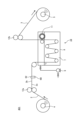
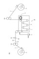
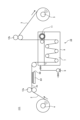
- FIG. 1 is a schematic diagram of a peeling device 101 according to a first embodiment of the invention; FIG. It is the schematic of the peeling apparatus 201 of the 2nd Embodiment of this invention. It is the schematic of the peeling apparatus 301 of the 3rd Embodiment of this invention.
- Figure 4 is a schematic top view of the coating damage mechanism 6 of Figure 3; It is the schematic of the peeling apparatus 401 of the 4th Embodiment of this invention.
- 6 is a schematic top view of the coating damage mechanism 6 of FIG. 5;
- FIG. 10 is a schematic top view of the coating damage mechanism 6 of FIG. 9; It is a schematic diagram of a peeling device 801 of an eighth embodiment of the present invention. 12 is a schematic top view of the coating damage mechanism 6 of FIG. 11; FIG. It is a schematic diagram of a peeling device 901 of a ninth embodiment of the present invention. 14 is a schematic top view of the coating damage mechanism 6 of FIG. 13; FIG. It is the schematic of the peeling apparatus 111 of the 10th Embodiment of this invention. 16 is a schematic top view of the coating damage mechanism 6 of FIG. 15; FIG.
- the inventors of the present invention have made intensive studies on a method of dissolving the coating resin in a short time using a cleaning agent to enable the coating to be peeled off at high speed. I found the device.
- the coating stripping method of the coated film of the present invention is a method for cleaning a coated film having a coating on the surface of a base film and peeling and removing the coating from the base film.
- the coating may be on one side or both sides of the base film, and is not particularly limited.
- the target coating of the coated film can be a coating of any composition, but a coating containing a water-soluble resin is preferable in consideration of the load on the environment.
- At least one of water-soluble polyester-based resin, polyester-urethane-based resin, acrylic-based resin, ethylene ionomer-based resin, polyvinyl alcohol-based resin, polyvinylpyrrolidone-based resin, ethylene-vinyl alcohol-based resin, and starch as the water-soluble resin. is more preferable as a main component.
- the film containing the water-soluble resin may be a single layer containing the water-soluble resin or a laminate of two or more layers containing the water-soluble resin. It may be a laminate of layers that do not contain.
- a coated release film containing a part of the coating in addition to the water-soluble resin as well as a release component is particularly preferable, and the effect of peeling the coating can be efficiently exhibited.
- the term "releasing component" as used herein refers to a component that increases the contact angle of the film surface with water, that is, reduces the surface energy of the film.
- the release component is, for example, a thermosetting silicone resin compound having a dimethylsiloxane as a main skeleton, or an organopolysiloxane containing an acryloyl group or a methacryloyl group, which is blended with a photopolymerization initiator and cured by irradiation with UV light.
- curable silicone resins such as UV curable silicone resin compounds that are cured, compounds having long-chain alkyl groups, and compounds having fluorine.
- the film may be a mixture of a water-soluble resin and a release component, or may be a laminate of a layer containing a water-soluble resin and a layer containing a release component.
- a layer containing a water-soluble resin is formed immediately above the base film, and then a layer containing a release component is formed on the outermost surface.
- the method of peeling the coating from the coated film of the present invention involves scratching, cutting, or forming holes in the coating from the coated surface of the coated film, or A scratch, cut, or hole is made to reach the coating from the non-coating surface of the coated film, then the cleaning solution is brought into contact with the coating, and then the coating containing the cleaning solution is peeled off from the coated film. That is, it is characterized by damaging the coating by scratching, cutting, or forming holes in the coating before contacting the cleaning solution with the coating, allowing the cleaning solution to penetrate efficiently into the coating, and cleaning the coating for a short period of time. to dissolve the film.
- “scratch” means to roughen the coating surface to form unevenness by physically rubbing the coating
- “cut” means to bring a sharp object into contact with the coating. In other words, it means to make a cut in the coating
- "form a hole” means to form a round hole, a polygonal hole, or the like in the coating.
- the dissolution of the water-soluble resin proceeds as the cleaning liquid permeates from the film surface.
- the contact area with the cleaning solution increases, and the coating has unevenness, cuts, and holes, which make it easier for the cleaning solution to spread to deeper positions in the thickness direction of the coating.
- soluble resin In the case where the coating of the target coated film is a layer containing a water-soluble resin immediately above the base film, and then a laminated coating containing a release component on the outermost surface, scratches penetrating the outermost layer By forming a groove, a notch, or a hole, the cleaning liquid can be efficiently guided to the underlying layer containing the water-soluble resin.
- the contact area with the cleaning liquid increases, and the layer containing the water-soluble resin has no unevenness, cuts, or holes. Since the cleaning liquid can easily spread to a deeper position in the thickness direction of the film, the water-soluble resin can be dissolved in a short time.
- the scratches, cuts, and holes may reach the base film, and in this case, the contact area with the cleaning liquid can be further increased in the thickness direction of the layer containing the water-soluble resin.
- thermosetting silicone resin compound having a main skeleton of dimethyl chloroxane which has high permeability to the cleaning liquid
- the cleaning liquid Permeates through the surface of the film and easily reaches the layer containing the water-soluble resin.
- the formation of scratches, cuts, and holes promotes penetration, so it dissolves the water-soluble resin in the lower layer in a short time. be able to.
- a scratch, cut, or hole may be formed from the non-coating surface to reach the coating.
- a force acts in the direction in which the layer containing the water-soluble resin is extruded from the base film, so that it is possible to avoid being buried in the base film.
- the washing liquid can be expected to permeate from the coating surface side and from the rear surface of the base film through scratches, cuts, and holes on the base film side, so that the dissolution of the water-soluble resin can be further promoted.
- the coated film when scratching, it is preferable to scratch the coated film while conveying it so that the angle (acute angle) formed by the longitudinal direction of the scratch and the conveying direction is 60° or less.
- the cut when the cut is made, it is preferable to make the cut so that the angle (acute angle) formed by the longitudinal direction of the cut and the conveying direction is 60° or less.
- a scratch or cut is made to reach a part of the base film, the conveying tension of the film is large, and the angle between the longitudinal direction of the scratch or cut and the conveying direction is 90 °. may act perpendicularly to scratches and cuts, leading to elongation and breakage of the base film.
- the angle between the longitudinal direction of the scratches or cuts and the conveying direction is preferably 60° or less, which makes it difficult for the film to stretch or break.
- the temperature of the cleaning liquid is preferably 150° C. or lower in order to suppress the dimensional change of the base film due to heat. Therefore, it is preferable that the temperature of the cleaning liquid is adjusted according to the configuration of the apparatus to be used so that the temperature of the cleaning liquid and the film temperature of the portion to which the cleaning liquid is applied are in the range of 40° C. to 150° C., respectively.
- the cleaning liquid As a method of applying the cleaning liquid to the film, it can be done by immersing the film with the coating in the cleaning liquid stored in the liquid tank. Alternatively, without using a liquid bath, the required amount of cleaning liquid may be sprayed onto the coated film, or if the cleaning liquid is water, steam may be blown. Moreover, as long as the cleaning liquid can be applied to the coating, it may be sprayed onto the coated film regardless of whether it is on one side or both sides.
- the peeling means may be any method such as bringing a rotating brush into contact with the film, scraping off the film by bringing a member having ridges into continuous contact with the film, or blowing off the film with an air nozzle.
- the water-soluble resin can be dissolved in a short time, so the film can be peeled off at high speed without enlarging the liquid tank or increasing the amount of waste liquid.
- a preferred embodiment of the apparatus for peeling a coating from a film with a coating (hereinafter referred to as a coating peeling apparatus) of the present invention will be described with reference to the drawings. It should be noted that the following description exemplifies an embodiment according to the present invention, and is not limited to this, and various modifications can be made without departing from the gist of the present invention.
- FIG. 1 is a schematic diagram of a coating stripping device 101 according to the first embodiment of the present invention.
- the coating stripping device 101 includes an unwinding device 4 for unwinding the film 2 with the coating and a winding device 5 for winding the base film 3 after stripping the coating. Between the unwinding device 4 and the winding device 5, a coating damage mechanism 6 for damaging the coating from the coated surface 2a of the coated film 2 and a coating damage mechanism 6 for damaging the coated film 2 are provided. It comprises a cleaning liquid application mechanism 10 for applying the cleaning liquid 7 and a peeling mechanism 11 for peeling the coating containing the cleaning liquid 7 from the coated film 2 to which the cleaning liquid 7 has been applied.
- the coated film 2 shown in FIG. 1 has a coating formed on one side of the film, and the coating damage mechanism 6 is installed facing the surface 2a on which the coating is formed.
- the coating damage mechanism 6 may be provided facing each coating surface.
- the cleaning liquid application mechanism 10 includes a liquid tank 8 for storing the cleaning liquid 7 and a pump 9 for feeding the cleaning liquid 7 from a tank (not shown), and conveys the coated film 2 while being immersed in the cleaning liquid 7 in the liquid tank 8. Thus, the cleaning liquid 7 is continuously applied to the coated film 2 .
- the cleaning liquid application mechanism 10 may be any mechanism such as a spray or a nozzle as long as it can apply the cleaning liquid 7 to the film.
- the coated film 2 unwound from the unwinding device 4 is conveyed by a conveying mechanism consisting of driving devices 12a and 12b, and the coating is damaged by the coating damage mechanism 6 before the cleaning liquid 7 is applied by the cleaning liquid applying mechanism 10. be injured.
- the coating damage mechanism 6 is composed of a brush roll.
- a brush roll capable of scratching the film efficiently, the surface of the film can be scraped to scratch it, and the effect of removing the film can also be expected.
- the brush roll can continuously scratch the coating by conveying the film 2 with the coating without rotating. In order to make more scratches, it is preferable to rotate the brush. The higher the number of revolutions, the more the bristles of the brush come into contact with the film, and the more scratches are produced. Further, when the brush roll is rotated, shavings of the coating caused by damage to the coating are not kept in one place and are discharged, which is preferable.
- the direction of rotation of the brush roll may be the same or opposite to the direction of transport of the coated film 2. Any method may be used, and there is no particular limitation as long as the film is damaged.
- the material of the bristles of the brush roll may be appropriately selected from resin, metal, animal hair, plant fiber, etc., and is not particularly limited as long as it can scratch the film, but the material should be harder than the film. can be easily scratched.
- the bristles are preferably fine and dense, allowing more wounds to be made.
- the coating damage mechanism 6 it is possible to use a roller or the like having unevenness on the cylindrical surface, and the coating can be scratched by rubbing.
- the surface of a roller or a round bar is knurled, or that an uneven shape is formed by etching or engraving.
- the stripping mechanism 11 consists of a brush roll similar to that used in the coating damage mechanism 6.
- the peeling mechanism 11 has a mechanism for rotating a brush roll made of metal or resin in the same or opposite direction as the conveying direction, and directly contacts the surface of the coated film 2 to peel off the cleaning liquid and the coating.
- a metal plate with a sharp tip that directly contacts the coated film 2 may be provided, or a resin plate may be provided.
- a thin metal plate may be provided.
- a waste cloth or cloth may be pressed against the coated film 2 and peeled off by wiping off the coated film, or may be blown off with an air nozzle.
- a structure may be added after the peeling mechanism 11 for rinsing, in which a clean cleaning liquid containing no impurities such as foreign matter is sprayed and dried with an air nozzle.
- FIG. 2 is a schematic diagram of a film stripping device 201 according to a second embodiment of the present invention.
- a backup roll 61 is provided at a position facing the brush roll of the coating damage mechanism 6 provided in the first embodiment, with the coated film 2 sandwiched therebetween. is.
- the brush roll can be reliably brought into contact with the coated film 2, which is preferable.
- the material of the bristles of the brush roll harder than the base film 3, the film can be penetrated and scratched including a part of the base film, so that the thickness of the film can be increased. Scratches can be applied in all directions.
- FIG. 3 is a schematic diagram of a coating stripping device 301 according to a third embodiment of the present invention.
- FIG. 4 is a schematic top view of the coating damage mechanism 6A of FIG.
- a plurality of cutters 62 are provided in the width direction as a coating damage mechanism 6A, and cuts 63 are provided in the coating. is to be inserted. 4
- the coating damage mechanism 6A is observed through the coated film 2, and the coating damage mechanism 6A and the notch 63 are not actually visible, so the cutter 62 and the notch 63 are illustrated with chain lines. .
- the cutter 62 can be lightly applied to the surface 2a on which the coating is formed, without penetrating the base film.
- a notch 63 can be made. It is also possible to cut not only the coating but also a part of the base film by adjusting the amount of pressing of the cutter 62 against the coating and the transport tension of the film 2 with the coating.
- the number of cuts 63 is determined by the number of cutters 62 and the pitch at which they are arranged.
- the cutter 62 may be a rotating round blade, or may be brought into contact with a sharp member having a sharp tip.
- the material of the cutter 62 is not particularly limited as long as it is made of metal, ceramic, resin, or the like and has a sharp tip.
- FIG. 5 is a schematic diagram of a film stripping device 401 according to a fourth embodiment of the invention.
- FIG. 6 is a schematic top view of the coating damage mechanism 6B of FIG.
- the amount of pressing of the cutter 62 of the coating damage mechanism 6A provided in the third embodiment is increased to cut through the base film. , incisions are made in the entire thickness direction of the film.
- the coating peeling apparatus 401 when the coated film 2 is immersed in the cleaning liquid 7 stored in the liquid tank 8 of the cleaning liquid applying mechanism 10, the cleaning liquid 7 passes through the notch 63 of the base film to the surface 2a on which the coating is formed and the surface 2a. Since the film is also applied from the surface 2b without the film, the water-soluble resin can be efficiently dissolved.
- the cleaning liquid application mechanism 10 When the cleaning liquid application mechanism 10 is configured to spray using a spray or the like, the cleaning liquid may be sprayed only from the surface 2a on which the film is formed, or preferably from both surfaces of the film 2 with the film. As in the case of immersion in the cleaning liquid 7 stored in the bath 8, the water-soluble resin can be efficiently dissolved.
- the cleaning liquid 7 when coatings are formed on both sides of the film and the cleaning liquid 7 is applied by spraying using a sprayer or the like, the cleaning liquid spreads over the coating through the cuts in the base film.
- the water-soluble resin can be dissolved as the application, it is more preferable to apply from both sides to efficiently dissolve the water-soluble resin.
- FIG. 7 is a schematic diagram of a film stripping device 501 according to a fifth embodiment of the present invention.
- a roller 64 having sharp protrusions on the cylindrical surface is brought into contact with the coating to form holes in the coating. It is something to do. By rotating the roller 64 at the same peripheral speed as the conveying speed of the coated film 2, it is possible to form holes having substantially the same shape as the protrusions formed on the surface. When the roller 64 is not rotated, a cut similar to that of the cutter of the third embodiment can be made.
- holes extending in the transport direction can be formed according to the peripheral speed difference.
- the shape of the hole is not particularly limited, and may be any shape such as a round hole, an elongated hole, or a polygonal hole.
- the sharp protrusions of the roller 64 can be realized, for example, by planting a needle-like member such as a pincushion on the surface of the cylinder, or by forming sharp protrusions on the surface of the cylinder by laser engraving or machining.
- the thickness of the coating is formed thinner than the thickness of the base film, so simply by pressing the roller 64 lightly against the surface of the coating, holes are formed in the coating without penetrating the base film. Is possible. It is also possible to form a hole that reaches not only the coating but also a part of the base film by adjusting the pressing amount of the roller 64 against the coating and the transport tension of the film 2 with the coating.
- the number of holes is determined by the number of projections and the pitch of the arrangement, so it can be adjusted as appropriate to obtain the desired holes.
- the material of the protrusions is not particularly limited as long as metal, ceramic, resin, or the like can be used, and at least holes can be formed in the film.
- FIG. 8 is a schematic diagram of a coating stripping device 601 according to the sixth embodiment of the present invention.
- the pressing amount of the roller 64 having sharp protrusions on the cylindrical surface of the fifth embodiment shown in FIG. 7 is increased to penetrate the base film.
- a hole is formed to form a hole in the entire thickness direction of the film.
- FIG. 9 is a schematic diagram of a film stripping device 701 according to a seventh embodiment of the invention.
- FIG. 10 is a schematic top view of the coating damage mechanism 6E of FIG.
- the cutter 62 provided in the third embodiment is provided on the side of the surface 2b where the coating is not formed, and penetrates the base film to cut into the coating. be.
- the cleaning solution 7 may not reach the details. There is In that case, if the surface 2b of the base film 2 with the coating is not formed with a scratch, the coating is pushed away from the base film, so there is no possibility that the coating will be buried in the base film. Therefore, it is preferable.
- FIG. 11 is a schematic diagram of a film stripping device 801 according to the eighth embodiment of the present invention.
- FIG. 12 is a schematic top view of the coating damage mechanism 6F of FIG.
- a roller 64 having sharp projections on the cylindrical surface provided in the sixth embodiment is provided on the side of the surface 2b where the film is not formed, and penetrates the base film. to form a hole 67 in the coating.
- the same functions and effects as those of the seventh embodiment described above are exhibited.
- FIG. 13 is a schematic diagram of a film stripping device 901 according to the ninth embodiment of the present invention.
- FIG. 14 is a schematic top view of the coating damage mechanism 6G of FIG.
- a coating damage mechanism 6G of the ninth embodiment has a sharp projection or a sharpened protrusion or a blade-shaped member 65 provided with a plurality of cutters, and a moving means (not shown) for the member 65 .
- the coating damage mechanism 6G is provided on the side of the surface 2a on which the coating is formed.
- a notch 62 is formed in a part of the material film in the thickness direction.
- ⁇ which is an angle (acute angle) formed by the longitudinal direction of the cut 62 and the transport direction
- ⁇ is preferably 60 degrees or less.
- a force obtained by multiplying the applied tension by sin ⁇ that is, a force of 87% or more of the tension acts on the cut 62 at right angles.
- the base film may be stretched or broken.
- the angle ⁇ is preferably 60° or less.
- FIG. 15 is a schematic diagram of the coating stripping device 111 of the tenth embodiment of the present invention.
- FIG. 16 is a schematic top view of the coating damage mechanism 6 of FIG.
- the coating damage mechanism 6H instead of the blade-shaped member 65 provided with a plurality of sharp projections or cutters in the ninth embodiment, a band-shaped brush 66 is brought into contact with the coating to scrape it. , and a wound 68 is made.
- the brush 66 is repeatedly moved back and forth while conveying the film 2 with the film, so that a scratch 68 oblique to the conveying direction can be made.
- ⁇ which is the angle (acute angle) formed by the longitudinal direction of the scratch 68 and the transport direction, be 60 degrees or less.
- a plurality of film damage mechanisms 6 to 6H shown in the first to tenth embodiments may be provided in the film transport direction.
- By providing a plurality of coating damage mechanisms 6 to 6H it becomes possible to form more scratches, cuts, and holes, and further high-speed peeling of the coating can be expected. It is also effective when the composition and thickness of the film make it difficult for the water-soluble resin to dissolve.
- the coating stripping method and the coating stripping apparatus of the present invention the coating can be stripped at high speed by dissolving the water-soluble resin from the surface of the coated film using the cleaning liquid in a short period of time. As a result, it is possible to obtain high-purity resin chips free of foreign matter at low cost without significantly increasing the environmental load.
- a film of polyvinyl alcohol resin having a thickness of 0.1 ⁇ m was formed as a layer containing a water-soluble resin on a base film made of polyethylene terephthalate and having a thickness of 30 ⁇ m and a width of 100 mm. Furthermore, a 0.1 ⁇ m-thick film of a curable silicone resin was formed thereon as a layer containing a release component, with reference to the coating material described in JP-A-2015-189226, as follows.
- thermosetting silicone manufactured by Shin-Etsu Chemical Co., Ltd., trade name “KS-847T”: 100 parts by mass
- Platinum catalyst manufactured by Shin-Etsu Chemical Co., Ltd., trade name “CAT-PL-50T”: 3 parts by mass Coating material Dissolves the above thermosetting silicone and platinum catalyst in a mixture of toluene and MEK as a solvent (toluene:MEK mass ratio is 1:1) so that the solid content is 1.8% by mass. It was prepared by Next, the coating material was applied on the polyvinyl alcohol resin film using a bar coater and dried in an oven at 90° C. for 20 seconds to form a release component film, thereby obtaining film a with a film.
- a film of polyvinyl alcohol resin having a thickness of 0.1 ⁇ m was formed as a layer containing a water-soluble resin on a base film made of polyethylene terephthalate and having a thickness of 30 ⁇ m and a width of 100 mm. Further thereon, as a layer containing a release component, a film of a resin containing a compound having a long-chain alkyl group with a film thickness of 0.1 ⁇ m is formed with reference to the coating material described in JP-A-2019-137005, as follows.
- a coating material is applied on the polyvinyl alcohol resin film using a gravure coater, pre-dried at 100° C., and then dried by heating at 160° C. to form a film of a release component, to obtain a film b with a film. Obtained.
- a film of polyvinyl alcohol resin having a thickness of 0.1 ⁇ m was formed as a layer containing a water-soluble resin on a base film made of polyethylene terephthalate and having a thickness of 30 ⁇ m and a width of 100 mm. Furthermore, a 0.1 ⁇ m-thick curable silicone resin film was formed thereon as a layer containing a release component, with reference to the coating material described in International Publication No. 2013/145864, as follows.
- release agent solution solid content: 20 mass%.
- This release agent solution was applied onto the polyvinyl alcohol resin film by a bar coater so that the thickness after curing was 0.97 ⁇ m, and dried at 80° C. for 1 minute. Thereafter, ultraviolet rays were irradiated (accumulated light quantity: 250 mJ/cm 2 ) to cure the release agent composition to form a coating of the release component, thereby obtaining a coated film c.
- Peelability of Coating Evaluation of peeling was measured by the following method using a commercially available dyne pen (surface energy: 30, 70 mN/m). It was determined that the surface energy of the sample surface was higher than the surface energy of the dyne pen when drawing was made on the sample surface with a dyne pen at room temperature of 23° C. and the state was maintained for 4 seconds or longer. If the coating of the release component of the coated films a to c remains on the surface, the surface energies of these are both less than 30 mN/m, so the reagent is repelled by the sample surface in any of the dyne pens, and the drawing cannot be retained.
- the surface energy is 70 mN/m or more, so any dyne pen can hold the drawing.
- the surface energy is 43.8 mN / m, so the Dyne pen of 30 mN / m
- the drawing is retained, but the dyne pen drawing of 70 mN/m cannot be retained.
- the intrinsic viscosity IV(R) of the sheet obtained in (i) above is measured.
- [ ⁇ ] (dl/g) is calculated by the following formula (a), and the obtained value is defined as the intrinsic viscosity.
- Example 1 As the coated film 2, the coated film a in which the coating was formed on one side of the substrate film was used, and set in the unwinding device 4 of the peeling device 101 shown in FIG.
- the film damage mechanism 6 used a brush roll, which was rotated at 500 rpm in the opposite direction to the film conveying direction, and brought into contact with the film surface to scratch and damage it.
- the bristles of the brush roll are made of nylon resin and have a wire diameter of 0.15 mm. Hot water of 60° C. was used as the cleaning liquid 7 .
- the cleaning liquid applying mechanism 10 has a cleaning liquid 7 stored in a liquid tank 8, and the coated film 2 is introduced into the liquid tank 8, and the film of the polyvinyl alcohol resin is dissolved while being immersed and transported in the cleaning liquid 7.
- the length of the coated film 2 immersed in the cleaning solution 7 was 0.5 m.
- the transport tension of the film was 60 N, and the transport speed was 50 m/min. Therefore, the time during which the coated film 2 is in contact with the cleaning liquid 7 is 0.6 seconds.
- the peeling mechanism 11 used a metal brush roll, which was rotated at 500 rpm in the opposite direction to the film conveying direction, and brought into contact with the surface of the film to peel the film.
- the substrate film 3 was wound by the winding device 5, the coating was peeled off, and the base film 3 was sampled.
- the peeled state of the coating was checked with a dyne pen, it was found that the curable silicone resin and the water-soluble polyvinyl alcohol resin as release components were mixed. It was confirmed that all the films were peeled off.
- a polyethylene terephthalate film was obtained without bubbles, gels, or the like in the molten polymer, and without any abnormalities such as pressure rise.
- the difference in intrinsic viscosity was 0.03, and it was confirmed that the quality of the recycled resin chips was within the acceptable range.
- Example 2 A coated film a in which a coating was formed on one side of a substrate film was used as the coated film 2 and set in the unwinding device 4 of the peeling device 901 shown in FIG. 13 .
- the film damage mechanism 6G uses a member 65 in which a plurality of stainless steel wires with a diameter of 1 mm are arranged at a pitch of 3 mm as sharp projections, is brought into contact along the film surface, and is reciprocated in the film width direction at a speed of 50 m / min. An incision 62 was made in the coating. As a result, the angle (acute angle) between the longitudinal direction of the slit 62 and the conveying direction was 45 degrees.
- a polyethylene terephthalate film was obtained without bubbles, gels, or the like in the molten polymer, and without any abnormalities such as pressure rise.
- the difference in intrinsic viscosity was 0.05, and it was confirmed that the quality of the recycled resin chips was within a satisfactory range.
- Example 3 Film b obtained by forming a coating on one side of a substrate film was used as film 2 with coating, and peeling was performed using the peeling apparatus 101 of Example 1 under the same conditions as in Example 1.
- the base film 3 was wound up by the winding device 5, and the base film 3 from which the coating had been peeled off was sampled. It was confirmed that all the films of the poly(vinyl alcohol) resin could be peeled off.
- a polyethylene terephthalate film was produced in the same manner as in Example 1 using recycled resin chips. A polyethylene terephthalate film was obtained without bubbles, gels, or the like in the molten polymer, and without any abnormalities such as pressure rise. The difference in intrinsic viscosity was 0.04, and it was confirmed that the quality of the recycled resin chips was within a satisfactory range.
- Example 4 Using the coated film c in which the coated film was formed on one side of the base film as the coated film 2, the peeling apparatus 101 of Example 1 was used to peel the film.
- the brush roll of the coating damage mechanism 6 was rotated at 1500 rpm in the opposite direction to the film conveying direction, and brought into contact with the coating surface to scratch and damage it. Other conditions were the same as in Example 1.
- the substrate film 3 was wound by the winding device 5, the coating was peeled off, and the base film 3 was sampled. When the peeled state of the coating was checked with a dyne pen, it was found that the curable silicone resin and the water-soluble polyvinyl alcohol resin as release components were mixed. It was confirmed that all the films were peeled off.
- a polyethylene terephthalate film was produced in the same manner as in Example 1 using recycled resin chips.
- a polyethylene terephthalate film was obtained without bubbles, gels, or the like in the molten polymer, and without any abnormalities such as pressure rise.
- the difference in intrinsic viscosity was 0.05, and it was confirmed that the quality of the recycled resin chips was within a satisfactory range.
- Example 1 A coated film a in which a coating was formed on one side of a substrate film was used as the coated film 2, and peeling was performed using the peeling device 101 of FIG. Other conditions were the same as in Example 1, and the coating was peeled off.
- the substrate film 3 was wound by the winding device 5, the coating was peeled off, and the base film 3 was sampled.
- the peeled state of the coating was checked with a dyne pen, it was found that the curable silicone resin and the water-soluble polyvinyl alcohol resin as release components were mixed. It was confirmed that part of the coating remained.
- a polyethylene terephthalate film was produced using the recycled resin chips in the same manner as in Example 1, and it was confirmed that air bubbles were mixed in the molten polymer. In addition, it was confirmed that the produced polyethylene terephthalate film had a difference of 0.23 in intrinsic viscosity, and the quality of the recycled resin chips could not withstand practical use.
- the method and device for peeling the coating from the coated film of the present invention are not limited to the film having the coating containing the water-soluble resin on one side of the base film, and the recycling having the coating containing the easily soluble resin layer. It can also be applied as a method and device for peeling coatings from resin films, paper films, and metal films.
Landscapes
- Chemical & Material Sciences (AREA)
- Engineering & Computer Science (AREA)
- Chemical Kinetics & Catalysis (AREA)
- Environmental & Geological Engineering (AREA)
- Mechanical Engineering (AREA)
- General Chemical & Material Sciences (AREA)
- Medicinal Chemistry (AREA)
- Health & Medical Sciences (AREA)
- Sustainable Development (AREA)
- Polymers & Plastics (AREA)
- Organic Chemistry (AREA)
- Life Sciences & Earth Sciences (AREA)
- Application Of Or Painting With Fluid Materials (AREA)
- Laminated Bodies (AREA)
- Separation, Recovery Or Treatment Of Waste Materials Containing Plastics (AREA)
- Cleaning In General (AREA)
Priority Applications (5)
| Application Number | Priority Date | Filing Date | Title |
|---|---|---|---|
| JP2022574723A JPWO2023106002A1 (https=) | 2021-12-09 | 2022-11-01 | |
| US18/713,750 US20250026902A1 (en) | 2021-12-09 | 2022-11-01 | Coating film removing method and coating film removing equipment for removing coating film from coated film |
| KR1020247012410A KR20240121709A (ko) | 2021-12-09 | 2022-11-01 | 피막 부착 필름으로부터의 피막의 박리 방법 및 피막의 박리 장치 |
| EP22903934.2A EP4446372A4 (en) | 2021-12-09 | 2022-11-01 | METHOD FOR SEPARING A COATING FILM FROM A COATED FILM AND DEVICE FOR SEPArating COATING FILMS |
| CN202280075943.3A CN118251295A (zh) | 2021-12-09 | 2022-11-01 | 从带被膜的膜剥离被膜的方法及被膜的剥离装置 |
Applications Claiming Priority (4)
| Application Number | Priority Date | Filing Date | Title |
|---|---|---|---|
| JP2021-199776 | 2021-12-09 | ||
| JP2021199776 | 2021-12-09 | ||
| JP2022-084238 | 2022-05-24 | ||
| JP2022084238 | 2022-05-24 |
Publications (1)
| Publication Number | Publication Date |
|---|---|
| WO2023106002A1 true WO2023106002A1 (ja) | 2023-06-15 |
Family
ID=86730206
Family Applications (1)
| Application Number | Title | Priority Date | Filing Date |
|---|---|---|---|
| PCT/JP2022/040912 Ceased WO2023106002A1 (ja) | 2021-12-09 | 2022-11-01 | 被膜付きフィルムからの被膜の剥離方法および被膜の剥離装置 |
Country Status (6)
| Country | Link |
|---|---|
| US (1) | US20250026902A1 (https=) |
| EP (1) | EP4446372A4 (https=) |
| JP (1) | JPWO2023106002A1 (https=) |
| KR (1) | KR20240121709A (https=) |
| TW (1) | TW202337572A (https=) |
| WO (1) | WO2023106002A1 (https=) |
Cited By (1)
| Publication number | Priority date | Publication date | Assignee | Title |
|---|---|---|---|---|
| US20250196198A1 (en) * | 2022-02-24 | 2025-06-19 | Toray Industries, Inc. | Coating film removing equipment and coating film removing method |
Citations (9)
| Publication number | Priority date | Publication date | Assignee | Title |
|---|---|---|---|---|
| JP2000025041A (ja) * | 1998-07-14 | 2000-01-25 | Unitika Ltd | 樹脂フィルムからのコート層の剥離方法 |
| JP2004169005A (ja) * | 2002-11-05 | 2004-06-17 | Toray Ind Inc | 積層フィルムのリサイクル方法およびリサイクル製品 |
| JP2004363140A (ja) * | 2003-06-02 | 2004-12-24 | Toray Ind Inc | 積層フィルムの剥離方法および剥離装置 |
| KR100878986B1 (ko) * | 2007-10-30 | 2009-01-15 | 유영산업주식회사 | 팽윤액을 이용한 필름 접착제분리기 |
| WO2013145864A1 (ja) | 2012-03-28 | 2013-10-03 | リンテック株式会社 | セラミックグリーンシート製造工程用剥離フィルム |
| JP2015189226A (ja) | 2014-03-31 | 2015-11-02 | 三井化学東セロ株式会社 | 離型フィルム |
| JP2019137005A (ja) | 2018-02-15 | 2019-08-22 | 東レフィルム加工株式会社 | 離型フィルム |
| JP2019209511A (ja) * | 2018-05-31 | 2019-12-12 | 日本ゼオン株式会社 | 分離装置、及び、樹脂フィルムの製造方法 |
| JP2021146682A (ja) * | 2020-03-23 | 2021-09-27 | 株式会社ユニチカテクノス | ポリ塩化ビニリデンコーティングフィルムからの熱可塑性樹脂フィルムの回収方法及び回収装置 |
Family Cites Families (3)
| Publication number | Priority date | Publication date | Assignee | Title |
|---|---|---|---|---|
| JPH07148737A (ja) * | 1993-11-29 | 1995-06-13 | Fuji Photo Film Co Ltd | 樹脂被覆紙から紙基材を採取する方法 |
| JP4989617B2 (ja) * | 2008-12-10 | 2012-08-01 | 株式会社 アイワプラスチックス | 剥離再生装置 |
| EP4129675A4 (en) * | 2020-03-31 | 2024-03-06 | Mitsubishi Chemical Corporation | POLYESTER RECYCLING SYSTEM AND METHOD |
-
2022
- 2022-11-01 WO PCT/JP2022/040912 patent/WO2023106002A1/ja not_active Ceased
- 2022-11-01 JP JP2022574723A patent/JPWO2023106002A1/ja active Pending
- 2022-11-01 US US18/713,750 patent/US20250026902A1/en active Pending
- 2022-11-01 KR KR1020247012410A patent/KR20240121709A/ko active Pending
- 2022-11-01 EP EP22903934.2A patent/EP4446372A4/en active Pending
- 2022-12-08 TW TW111147127A patent/TW202337572A/zh unknown
Patent Citations (9)
| Publication number | Priority date | Publication date | Assignee | Title |
|---|---|---|---|---|
| JP2000025041A (ja) * | 1998-07-14 | 2000-01-25 | Unitika Ltd | 樹脂フィルムからのコート層の剥離方法 |
| JP2004169005A (ja) * | 2002-11-05 | 2004-06-17 | Toray Ind Inc | 積層フィルムのリサイクル方法およびリサイクル製品 |
| JP2004363140A (ja) * | 2003-06-02 | 2004-12-24 | Toray Ind Inc | 積層フィルムの剥離方法および剥離装置 |
| KR100878986B1 (ko) * | 2007-10-30 | 2009-01-15 | 유영산업주식회사 | 팽윤액을 이용한 필름 접착제분리기 |
| WO2013145864A1 (ja) | 2012-03-28 | 2013-10-03 | リンテック株式会社 | セラミックグリーンシート製造工程用剥離フィルム |
| JP2015189226A (ja) | 2014-03-31 | 2015-11-02 | 三井化学東セロ株式会社 | 離型フィルム |
| JP2019137005A (ja) | 2018-02-15 | 2019-08-22 | 東レフィルム加工株式会社 | 離型フィルム |
| JP2019209511A (ja) * | 2018-05-31 | 2019-12-12 | 日本ゼオン株式会社 | 分離装置、及び、樹脂フィルムの製造方法 |
| JP2021146682A (ja) * | 2020-03-23 | 2021-09-27 | 株式会社ユニチカテクノス | ポリ塩化ビニリデンコーティングフィルムからの熱可塑性樹脂フィルムの回収方法及び回収装置 |
Non-Patent Citations (1)
| Title |
|---|
| See also references of EP4446372A4 |
Cited By (1)
| Publication number | Priority date | Publication date | Assignee | Title |
|---|---|---|---|---|
| US20250196198A1 (en) * | 2022-02-24 | 2025-06-19 | Toray Industries, Inc. | Coating film removing equipment and coating film removing method |
Also Published As
| Publication number | Publication date |
|---|---|
| KR20240121709A (ko) | 2024-08-09 |
| EP4446372A4 (en) | 2025-12-03 |
| EP4446372A1 (en) | 2024-10-16 |
| TW202337572A (zh) | 2023-10-01 |
| US20250026902A1 (en) | 2025-01-23 |
| JPWO2023106002A1 (https=) | 2023-06-15 |
Similar Documents
| Publication | Publication Date | Title |
|---|---|---|
| JP7780579B2 (ja) | ポリエステルフィルムの製造方法、およびポリエステルペレットの製造方法 | |
| CN115362201B (zh) | 聚酯的再循环系统和再循环方法 | |
| EP4306223A1 (en) | Method for separating coating from film with coating, and apparatus for separating coating | |
| KR101766574B1 (ko) | 장척상의 점착 필름 | |
| TWI666304B (zh) | 光學膜之製造方法 | |
| WO2023106002A1 (ja) | 被膜付きフィルムからの被膜の剥離方法および被膜の剥離装置 | |
| CN107709488B (zh) | 粘合膜的制造方法和偏振片的制造方法 | |
| CN104422981B (zh) | 光学膜的制造方法 | |
| WO2024058133A1 (ja) | コーティング層の除去方法及びコーティング層の除去装置 | |
| EP3371823B1 (de) | Verfahren zur behandlung von millimeter-, mikrometer- oder nanometerstrukturen auf einer oberfläche eines substrats | |
| CN118251295A (zh) | 从带被膜的膜剥离被膜的方法及被膜的剥离装置 | |
| CN107003467B (zh) | 偏振膜的制造方法 | |
| JP5284844B2 (ja) | ロール状金型を用いた光学シートの製造方法 | |
| WO2023189669A1 (ja) | コーティング層の除去方法及びコーティング層の除去装置 | |
| JPWO2023106002A5 (https=) | ||
| CN121057643A (zh) | 被膜剥离装置及被膜剥离方法 | |
| WO2023218811A1 (ja) | 被膜剥離方法および被膜剥離装置 | |
| JP2001179913A (ja) | 易接着性ポリエステルフィルム | |
| JP2002120210A (ja) | セラミックシート製造用離型フィルム | |
| KR102795567B1 (ko) | 이접착성 폴리에스테르 필름 및 그의 제조방법 | |
| CN121240937A (zh) | 被膜剥离装置及被膜剥离方法 | |
| JP2024129276A (ja) | 再生二軸配向ポリエステルフィルム | |
| WO2026044237A1 (en) | Method and system for addressing buildup on printer cutting elements | |
| TWM679160U (zh) | 裁刀裝置 |
Legal Events
| Date | Code | Title | Description |
|---|---|---|---|
| WWE | Wipo information: entry into national phase |
Ref document number: 2022574723 Country of ref document: JP |
|
| 121 | Ep: the epo has been informed by wipo that ep was designated in this application |
Ref document number: 22903934 Country of ref document: EP Kind code of ref document: A1 |
|
| WWE | Wipo information: entry into national phase |
Ref document number: 202280075943.3 Country of ref document: CN |
|
| WWE | Wipo information: entry into national phase |
Ref document number: 12024551221 Country of ref document: PH |
|
| WWE | Wipo information: entry into national phase |
Ref document number: 18713750 Country of ref document: US |
|
| WWE | Wipo information: entry into national phase |
Ref document number: 11202403483P Country of ref document: SG |
|
| WWE | Wipo information: entry into national phase |
Ref document number: 2022903934 Country of ref document: EP |
|
| NENP | Non-entry into the national phase |
Ref country code: DE |
|
| ENP | Entry into the national phase |
Ref document number: 2022903934 Country of ref document: EP Effective date: 20240709 |