WO2023218811A1 - 被膜剥離方法および被膜剥離装置 - Google Patents
被膜剥離方法および被膜剥離装置 Download PDFInfo
- Publication number
- WO2023218811A1 WO2023218811A1 PCT/JP2023/014111 JP2023014111W WO2023218811A1 WO 2023218811 A1 WO2023218811 A1 WO 2023218811A1 JP 2023014111 W JP2023014111 W JP 2023014111W WO 2023218811 A1 WO2023218811 A1 WO 2023218811A1
- Authority
- WO
- WIPO (PCT)
- Prior art keywords
- base film
- film
- coating
- peeling
- peeling member
- Prior art date
Links
- 238000000576 coating method Methods 0.000 title claims abstract description 222
- 239000011248 coating agent Substances 0.000 title claims abstract description 214
- 238000000034 method Methods 0.000 title claims abstract description 52
- 229920005989 resin Polymers 0.000 claims abstract description 76
- 239000011347 resin Substances 0.000 claims abstract description 76
- 238000004140 cleaning Methods 0.000 claims description 82
- 239000007788 liquid Substances 0.000 claims description 82
- 230000007246 mechanism Effects 0.000 claims description 22
- XLYOFNOQVPJJNP-UHFFFAOYSA-N water Substances O XLYOFNOQVPJJNP-UHFFFAOYSA-N 0.000 claims description 21
- 229920002050 silicone resin Polymers 0.000 claims description 16
- 238000004804 winding Methods 0.000 claims description 16
- 238000011144 upstream manufacturing Methods 0.000 claims description 13
- 230000001154 acute effect Effects 0.000 claims description 7
- 238000013459 approach Methods 0.000 claims description 4
- 238000005406 washing Methods 0.000 abstract 3
- 239000011247 coating layer Substances 0.000 abstract 1
- 239000010410 layer Substances 0.000 description 17
- 239000004372 Polyvinyl alcohol Substances 0.000 description 16
- 229920002451 polyvinyl alcohol Polymers 0.000 description 16
- 239000000463 material Substances 0.000 description 14
- -1 methacryloyl group Chemical group 0.000 description 14
- 239000000243 solution Substances 0.000 description 12
- 230000007613 environmental effect Effects 0.000 description 11
- 229920000139 polyethylene terephthalate Polymers 0.000 description 11
- 239000005020 polyethylene terephthalate Substances 0.000 description 11
- 238000010586 diagram Methods 0.000 description 7
- 238000007689 inspection Methods 0.000 description 7
- 229910052751 metal Inorganic materials 0.000 description 7
- 239000002184 metal Substances 0.000 description 7
- 238000003825 pressing Methods 0.000 description 7
- 239000000758 substrate Substances 0.000 description 7
- 230000037303 wrinkles Effects 0.000 description 7
- YXFVVABEGXRONW-UHFFFAOYSA-N Toluene Chemical compound CC1=CC=CC=C1 YXFVVABEGXRONW-UHFFFAOYSA-N 0.000 description 6
- 150000001875 compounds Chemical class 0.000 description 6
- 239000002904 solvent Substances 0.000 description 6
- 239000000919 ceramic Substances 0.000 description 5
- 238000004090 dissolution Methods 0.000 description 5
- 230000000694 effects Effects 0.000 description 5
- 239000003960 organic solvent Substances 0.000 description 5
- XEEYBQQBJWHFJM-UHFFFAOYSA-N Iron Chemical compound [Fe] XEEYBQQBJWHFJM-UHFFFAOYSA-N 0.000 description 4
- 238000011156 evaluation Methods 0.000 description 4
- 239000000203 mixture Substances 0.000 description 4
- 229920003023 plastic Polymers 0.000 description 4
- 239000004033 plastic Substances 0.000 description 4
- TVEXGJYMHHTVKP-UHFFFAOYSA-N 6-oxabicyclo[3.2.1]oct-3-en-7-one Chemical compound C1C2C(=O)OC1C=CC2 TVEXGJYMHHTVKP-UHFFFAOYSA-N 0.000 description 3
- 230000005856 abnormality Effects 0.000 description 3
- 238000001035 drying Methods 0.000 description 3
- 239000000499 gel Substances 0.000 description 3
- 229920000642 polymer Polymers 0.000 description 3
- 238000012545 processing Methods 0.000 description 3
- 238000007790 scraping Methods 0.000 description 3
- 239000007921 spray Substances 0.000 description 3
- 229920001187 thermosetting polymer Polymers 0.000 description 3
- 230000000052 comparative effect Effects 0.000 description 2
- 239000004744 fabric Substances 0.000 description 2
- 229910052742 iron Inorganic materials 0.000 description 2
- 238000004519 manufacturing process Methods 0.000 description 2
- BASFCYQUMIYNBI-UHFFFAOYSA-N platinum Chemical compound [Pt] BASFCYQUMIYNBI-UHFFFAOYSA-N 0.000 description 2
- 229920001296 polysiloxane Polymers 0.000 description 2
- 229910001220 stainless steel Inorganic materials 0.000 description 2
- 239000010935 stainless steel Substances 0.000 description 2
- 238000004383 yellowing Methods 0.000 description 2
- ISPYQTSUDJAMAB-UHFFFAOYSA-N 2-chlorophenol Chemical compound OC1=CC=CC=C1Cl ISPYQTSUDJAMAB-UHFFFAOYSA-N 0.000 description 1
- 239000004925 Acrylic resin Substances 0.000 description 1
- 229920000178 Acrylic resin Polymers 0.000 description 1
- 229920012753 Ethylene Ionomers Polymers 0.000 description 1
- 229920000219 Ethylene vinyl alcohol Polymers 0.000 description 1
- PXGOKWXKJXAPGV-UHFFFAOYSA-N Fluorine Chemical compound FF PXGOKWXKJXAPGV-UHFFFAOYSA-N 0.000 description 1
- 229920000426 Microplastic Polymers 0.000 description 1
- 229920002472 Starch Polymers 0.000 description 1
- NIXOWILDQLNWCW-UHFFFAOYSA-N acrylic acid group Chemical group C(C=C)(=O)O NIXOWILDQLNWCW-UHFFFAOYSA-N 0.000 description 1
- 125000003647 acryloyl group Chemical group O=C([*])C([H])=C([H])[H] 0.000 description 1
- 239000000853 adhesive Substances 0.000 description 1
- 230000001070 adhesive effect Effects 0.000 description 1
- 125000000217 alkyl group Chemical group 0.000 description 1
- JRPBQTZRNDNNOP-UHFFFAOYSA-N barium titanate Chemical compound [Ba+2].[Ba+2].[O-][Ti]([O-])([O-])[O-] JRPBQTZRNDNNOP-UHFFFAOYSA-N 0.000 description 1
- 229910002113 barium titanate Inorganic materials 0.000 description 1
- 230000015572 biosynthetic process Effects 0.000 description 1
- 239000003054 catalyst Substances 0.000 description 1
- 239000003985 ceramic capacitor Substances 0.000 description 1
- 239000003153 chemical reaction reagent Substances 0.000 description 1
- 238000011109 contamination Methods 0.000 description 1
- 238000005520 cutting process Methods 0.000 description 1
- 230000007423 decrease Effects 0.000 description 1
- 230000003247 decreasing effect Effects 0.000 description 1
- 238000001514 detection method Methods 0.000 description 1
- 230000006866 deterioration Effects 0.000 description 1
- 230000002542 deteriorative effect Effects 0.000 description 1
- 239000004715 ethylene vinyl alcohol Substances 0.000 description 1
- 239000012530 fluid Substances 0.000 description 1
- 239000011737 fluorine Substances 0.000 description 1
- 229910052731 fluorine Inorganic materials 0.000 description 1
- 239000011521 glass Substances 0.000 description 1
- 229920006015 heat resistant resin Polymers 0.000 description 1
- 238000010438 heat treatment Methods 0.000 description 1
- RZXDTJIXPSCHCI-UHFFFAOYSA-N hexa-1,5-diene-2,5-diol Chemical compound OC(=C)CCC(O)=C RZXDTJIXPSCHCI-UHFFFAOYSA-N 0.000 description 1
- 238000007654 immersion Methods 0.000 description 1
- 239000003999 initiator Substances 0.000 description 1
- 229910010272 inorganic material Inorganic materials 0.000 description 1
- 239000011147 inorganic material Substances 0.000 description 1
- 238000009434 installation Methods 0.000 description 1
- 238000003754 machining Methods 0.000 description 1
- 239000012528 membrane Substances 0.000 description 1
- 150000002739 metals Chemical class 0.000 description 1
- 239000011259 mixed solution Substances 0.000 description 1
- 239000011368 organic material Substances 0.000 description 1
- 230000035699 permeability Effects 0.000 description 1
- 229910052697 platinum Inorganic materials 0.000 description 1
- 238000005498 polishing Methods 0.000 description 1
- 229920000728 polyester Polymers 0.000 description 1
- 229920001225 polyester resin Polymers 0.000 description 1
- 239000004645 polyester resin Substances 0.000 description 1
- 229920000036 polyvinylpyrrolidone Polymers 0.000 description 1
- 239000001267 polyvinylpyrrolidone Substances 0.000 description 1
- 235000013855 polyvinylpyrrolidone Nutrition 0.000 description 1
- 238000005086 pumping Methods 0.000 description 1
- 239000002994 raw material Substances 0.000 description 1
- 238000011160 research Methods 0.000 description 1
- 239000002356 single layer Substances 0.000 description 1
- 238000009751 slip forming Methods 0.000 description 1
- 239000007787 solid Substances 0.000 description 1
- 239000008107 starch Substances 0.000 description 1
- 235000019698 starch Nutrition 0.000 description 1
- 239000000126 substance Substances 0.000 description 1
- 239000004094 surface-active agent Substances 0.000 description 1
- 229920002803 thermoplastic polyurethane Polymers 0.000 description 1
- 229920005992 thermoplastic resin Polymers 0.000 description 1
- 238000012546 transfer Methods 0.000 description 1
- 238000007740 vapor deposition Methods 0.000 description 1
- 239000002699 waste material Substances 0.000 description 1
- 239000002351 wastewater Substances 0.000 description 1
Images


Classifications
-
- B—PERFORMING OPERATIONS; TRANSPORTING
- B29—WORKING OF PLASTICS; WORKING OF SUBSTANCES IN A PLASTIC STATE IN GENERAL
- B29B—PREPARATION OR PRETREATMENT OF THE MATERIAL TO BE SHAPED; MAKING GRANULES OR PREFORMS; RECOVERY OF PLASTICS OR OTHER CONSTITUENTS OF WASTE MATERIAL CONTAINING PLASTICS
- B29B17/00—Recovery of plastics or other constituents of waste material containing plastics
- B29B17/02—Separating plastics from other materials
-
- C—CHEMISTRY; METALLURGY
- C08—ORGANIC MACROMOLECULAR COMPOUNDS; THEIR PREPARATION OR CHEMICAL WORKING-UP; COMPOSITIONS BASED THEREON
- C08J—WORKING-UP; GENERAL PROCESSES OF COMPOUNDING; AFTER-TREATMENT NOT COVERED BY SUBCLASSES C08B, C08C, C08F, C08G or C08H
- C08J11/00—Recovery or working-up of waste materials
- C08J11/04—Recovery or working-up of waste materials of polymers
- C08J11/06—Recovery or working-up of waste materials of polymers without chemical reactions
-
- Y—GENERAL TAGGING OF NEW TECHNOLOGICAL DEVELOPMENTS; GENERAL TAGGING OF CROSS-SECTIONAL TECHNOLOGIES SPANNING OVER SEVERAL SECTIONS OF THE IPC; TECHNICAL SUBJECTS COVERED BY FORMER USPC CROSS-REFERENCE ART COLLECTIONS [XRACs] AND DIGESTS
- Y02—TECHNOLOGIES OR APPLICATIONS FOR MITIGATION OR ADAPTATION AGAINST CLIMATE CHANGE
- Y02W—CLIMATE CHANGE MITIGATION TECHNOLOGIES RELATED TO WASTEWATER TREATMENT OR WASTE MANAGEMENT
- Y02W30/00—Technologies for solid waste management
- Y02W30/50—Reuse, recycling or recovery technologies
- Y02W30/62—Plastics recycling; Rubber recycling
Definitions
- the present invention relates to a peeling method and a peeling device that can efficiently remove a film on the surface of a thermoplastic resin film.
- the general manufacturing method for this MLCC includes the steps of using a release film in which a release layer is formed on a plastic base film as a carrier sheet, and forming a ceramic green sheet layer on the release film; There is a step of peeling off the ceramic green sheet layer to obtain a ceramic green sheet. In this step, the release film from which the ceramic sheet has been peeled off is discarded as unnecessary material.
- the increase in release film waste due to the rapid increase in MLCC quantities in recent years has become an environmental issue, and efforts are becoming more active to reuse plastic base films.
- the components of the release layer contained in the release film are generally different from those of the base film from the viewpoint of release properties, so the release film with the release layer can be used as is.
- a recycled film is formed by remelting, stable film formation cannot be achieved because the components of the release layer are present as foreign matter.
- Patent Document 1 as a method for removing a mold release component from a mold release film, a mold release film in which a water-soluble resin layer is formed between a base film and a mold release layer is used, and the mold release film is soaked in a hot water bath for 2 seconds or more. A method is disclosed in which the release layer is peeled off by rubbing the surface of the release film with a brush roll after immersion.
- Patent Document 2 as a method for removing a film from a base film having a film formed by coating, a dissolution tank storing an organic solvent is provided, and the bottom of the dissolution tank is provided with a solution that can be brought into contact with the surface of the film.
- An apparatus is disclosed in which a scraper is installed to dissolve and remove a coating from a substrate film having a coating being conveyed.
- the coating peeling method disclosed in Patent Document 2 uses an organic solvent to dissolve and remove the coating, and as in Patent Document 1, a large amount of organic solvent is used to continuously develop the initial peeling ability. Since a solvent is required, there is a problem in that the environmental burden becomes significantly large.
- the scraper installed at the bottom of the dissolution tank directly contacts the coating surface of the substrate film having the coating being transported to scrape off the coating, but since the substrate film is transported in the liquid, When scraping off a coating with a scraper, organic solvents tend to be present between the coating surface and the scraper, and sufficient scraping ability may not be obtained.
- the present invention has developed a coating containing a water-soluble resin on one side of the base film.
- a film peeling method and a film peeling device capable of efficiently and reliably peeling off a film by dissolving a water-soluble resin from the surface of a base film using a small amount of cleaning liquid.
- the film peeling method of the present invention that solves the above problems is a method of peeling a film containing a water-soluble resin from a base film having the film on at least one side, wherein a cleaning liquid containing water as a main component is Applying the cleaning liquid to the coating in an amount ranging from 3 to 650 ml per 1 m 2 of surface area of the coating, bringing a peeling member into contact with the surface of the coating to which the cleaning liquid has been applied, and applying the angle formed by the base film through the peeling member. is in the range of 20 to 150°, and while applying a tension in the range of 10 to 1000 N/m in at least one longitudinal direction of the base film, the base film is attached to the peeling member.
- the coating is peeled off from the base film by relatively moving it in the longitudinal direction of the base film.
- the length in the longitudinal direction of the base film in the range in which the peeling member is in contact with the surface of the film is a contact length L [m]
- the contact length is L [m].
- the plane passing through the center of the length and perpendicular to the surface of the peeling member is the vertical plane, the side where the base film approaches the peeling member relatively is the upstream side, and the side with respect to the peeling member is the upstream side.
- the contact length L is in the range of 1 x 10 -5 to 1 x 10 -3 m, with the side where the base film is relatively separated being the downstream side, and the vertical plane and the upstream side of the vertical plane.
- the coating peeling method of [1] or [2] above applies to the two surfaces that constitute the peeling member and sandwiching the ridgeline where the peeling member starts to come into contact with the surface of the coating. It is preferable that the angle between the surface facing the base film before contacting the ridgeline and the base film before contacting the ridgeline is 5° or more. [4] In the film peeling method of any one of [1] to [3] above, it is preferable that the film contains a curable silicone resin.
- the film peeling device of the present invention that solves the above problems is a device for peeling a film containing a water-soluble resin from a base film that has a film on at least one side, and which applies a cleaning liquid to the film.
- a cleaning liquid applying mechanism for peeling off the coating coated with the cleaning liquid from the base film, and a peeling member for peeling off the coating coated with the cleaning liquid from the base film, the base film being moved relative to the peeling member in the longitudinal direction of the base film.
- a tension applying mechanism for applying tension in at least one longitudinal direction of the base film, and the cleaning liquid application mechanism applies the cleaning liquid to a surface area of 1 m 2 of the coating film.
- the cleaning liquid is adjusted to be applied in an amount in the range of 3 to 650 ml per wash, and the peeling member is in contact with the surface of the coating to which the cleaning liquid has been applied, and the cleaning liquid is applied between the base films through the peeling member.
- the tension applying mechanism is adjusted to apply a tension in the range of 10 to 1000 N/m.
- the length L in the longitudinal direction of the base film in the range where the peeling member contacts the surface of the coating is 1 ⁇ 10 ⁇ 5 to 1 ⁇ 10 ⁇ 3 .
- the range is preferably m.
- the film peeling device of [5] or [6] above includes an unwinding device for unwinding the base film having the film wound into a roll, and the base film from which the film has been peeled. It is preferable to include a winding device for winding up.
- the base film before contact with the peeling member is the “base film with a coating”
- the base film after contact with the peeling member is the “base film from which the coating has been peeled off”
- the above [1] ] to [4] and the film peeling apparatus described in [5] to [7] above, both are referred to as the "base film” without any particular distinction.
- a film can be efficiently and reliably peeled off with a small amount of cleaning liquid from a base film having a film containing a water-soluble resin on one side of the base film.
- FIG. 1 is a schematic diagram of a peeling device according to an embodiment of the present invention.
- FIG. 2 is a schematic diagram of a peeling member of a first embodiment of the peeling apparatus of the present invention. It is a schematic diagram of the peeling member of 2nd Embodiment in the peeling apparatus of this invention. It is a schematic diagram of the peeling member of 3rd Embodiment in the peeling apparatus of this invention.
- 2 is a graph showing the results of peeling off a film under the conditions of Example 1.
- 3 is a graph showing the results of peeling off a film under the conditions of Example 2.
- 3 is a graph showing the results of peeling off a film under the conditions of Example 3.
- the inventors of the present invention have conducted extensive research into a method for efficiently and reliably removing a coating from the surface of a coated film, which has a coating containing a water-soluble resin on one side of the base film, using a very small amount of cleaning liquid.
- the inventors have discovered the following film removal method and film removal apparatus.
- the method of peeling a film from a base film having a film according to the present invention targets a base film having a film containing a water-soluble resin on at least one side of the base film, and cleans the film and peels the film from the base film. This is how to remove it.
- the coating may be present on one side or both sides of the base film, and is not particularly limited.
- the target base film having a coating may be a base film having a coating containing a water-soluble resin in consideration of the environmental load, as well as a coating containing another water-soluble resin.
- the water-soluble resin includes at least one of water-soluble polyester resin, polyester urethane resin, acrylic resin, ethylene ionomer resin, polyvinyl alcohol resin, polyvinylpyrrolidone resin, ethylene-vinyl alcohol resin, and starch. It is more preferable to use seeds as a main component.
- a film containing a water-soluble resin may be a single layer containing a water-soluble resin or a laminate of two or more layers containing a water-soluble resin. It may also be a laminate of layers that do not contain such a material.
- a release film with a coating containing a release component in addition to the water-soluble resin in a part of the coating is particularly preferred, and can efficiently exhibit the effect of peeling off the coating.
- the release component referred to here is a component that increases the contact angle of the film surface with water, that is, reduces the surface energy of the film.
- Type silicone resin compounds, UV-curable silicone resin compounds in which a photopolymerization initiator is blended with an organopolysiloxane containing an acryloyl or methacryloyl group and cured by irradiation with UV light, and other types have long-chain alkyl groups. Compounds and compounds containing fluorine can be mentioned.
- the coating may be a mixture of a water-soluble resin and a release component, or may be a stack of layers of each.
- a layer containing a water-soluble resin is formed directly above the base film, and then a layer containing a mold release component is formed on the outermost surface, and the mold release component has water permeability.
- the coating peeling method of the present invention includes applying a cleaning liquid containing water as a main component to the coating surface of a base film having a coating containing the above-mentioned water-soluble resin on at least one side in an amount of 3 to 650 ml per 1 m 2 of surface area of the coating. Then, the peeling member is brought into contact with the surface of the coating to which the cleaning liquid has been applied, and the angle formed by the base film through the peeling member is in the range of 20 to 150°, and at least one direction in the longitudinal direction of the base film is applied.
- a film peeling method in which a film is removed from a base film having a film by moving the base film relative to a peeling member in its longitudinal direction while applying a tension in the range of 10 to 1000 N/m. be.
- the method for applying the cleaning liquid to the coating surface in the coating removal method of the present invention may be any method.
- the cleaning liquid may be applied in the form of droplets using a spray nozzle, or the cleaning liquid may be applied in the form of droplets using a high-pressure washer or a steam generator.
- a high-pressure or high-temperature cleaning solution may be applied using a high-pressure or high-temperature cleaning solution.
- the amount of the cleaning liquid applied is preferably adjusted as appropriate depending on the properties and thickness of the film to be peeled off, and is preferably appropriately controlled by the method of applying the cleaning liquid.
- the cleaning solution may be managed by pumping it with a metering pump, a flow meter may be installed in the middle of the flow path where the cleaning solution is sent, or the cleaning solution applied to the coating surface may be collected and its mass measured. Good too.
- the water-soluble resin contains cleaning liquid and it is difficult to measure the mass, collect the base film with the coating, the applied cleaning liquid, and the peeled coating, and calculate the amount of cleaning liquid applied. It may be calculated.
- the amount of cleaning liquid applied should be 3 ml or more per 1 m 2 of surface area of the coating. It was confirmed that the effect of peeling off the film could be obtained. It has been confirmed that if the amount of water is less than 3 ml per 1 m2 of surface area of the coating, the effectiveness of coating removal may be reduced, especially when the humidity of the surrounding environment is low. The drying of the cleaning liquid may proceed before it is swollen, and the effect of peeling the film may not be obtained.
- the larger the amount of cleaning liquid applied the more reliably the coating containing the water-soluble resin can be dissolved or swollen, and the more effectively the coating is peeled off.
- the effect of peeling the coating can be obtained by applying 650 ml of cleaning liquid to the coating surface per 1 m 2 of surface area of the coating.
- the cleaning liquid used in the film removal method of the present invention can be effective in any solvent as long as it can dissolve the water-soluble resin, but in order to reduce the environmental burden, it is preferable to use water. Furthermore, by adding a surfactant or the like to a water-based composition, the wettability between the cleaning liquid and the coating surface may be improved, and the cleaning liquid may be easily spread over the entire coating.
- Examples of the peeling member in the film peeling method of the present invention include, but are not limited to, a scraper, a cloth, a metal plate, a rotating brush roll, etc., and the peeling member directly contacts the base film having the film, Any means may be used as long as the coating can be physically peeled off. Further, it is preferable that the peeling member be brought into direct contact with the coated surface of the base film by pressing the peeling member, and the base film is maintained in a bent or curved state by the peeling member. The film can be peeled off from the base film by moving the base film relative to the peeling member in the longitudinal direction while keeping the base film in place.
- the above-mentioned bent or curved base film has an angle formed by the base film in the range of 20 to 150° through the peeling member, and tension is applied in at least one longitudinal direction in the range of 10 to 1000 N/m. It is preferable that the peeling member can be strongly pressed against the coating surface of the base film, so that the coating dissolved or swollen by the cleaning liquid can be efficiently and reliably peeled off. Therefore, the narrower the area in which the peeling member contacts the base film having the coating, the more strongly the peeling member can be locally pressed against the coated surface of the base film, which is preferable.
- a scraper, a corner of a metal plate, etc. are preferably used.
- the angle formed by the base film through the peeling member is less than 20°, it is not practical because the space in which the peeling member is installed becomes very narrow.
- the angle is made larger than 150°, the force pressing the release member against the coating surface of the base film will be weaker, but it may still be possible to peel off some coatings that have easy-to-peel properties. It could be confirmed.
- tension fluctuations occur when the base film and the release member are moved relative to each other in the longitudinal direction of the base film, or if the peel speed is increased, there may be a gap between the base film and the release member. It has been confirmed that air is easily entrained, and a part of the film may not be peeled off, but may slip through and remain on the base film.
- the film peeling effect was achieved when the tension applied in at least one longitudinal direction of the base film was 10 N/m or more.
- the base film is conveyed with an applied tension of less than 10 N/m, stable conveyance is not possible due to the low tension, and the tension fluctuates greatly and meandering occurs during conveyance. It may become impossible to peel off the coating.
- a tension exceeding 1000 N/m is applied, the base film is strongly pulled in one direction, resulting in multiple corrugated iron wrinkles occurring in the width direction of the base film in the longitudinal direction. Some corrugated iron wrinkles form creases at locations where they come into contact with the peeling member, and the film may not be able to be peeled off at the creases.
- the film is peeled from the base film having the film by moving the base film having the film in the preferred form described above relative to the peeling member in its longitudinal direction.
- Any means may be used to move the base film relative to the peeling member; the peeling member may be fixed and only the base film may be transported, or the base film may be moved relative to the stationary base film.
- the peeling member may be moved.
- both the peeling member and the base film may be moving, and both may be moving in the same direction or in different directions.
- the target base film has a coating that is continuous or discontinuous in the longitudinal direction of the base film
- the base film is conveyed and the peeling member is attached to the base film. It is preferable to peel off the film while the film is in a state where it extends and is fixed in the lateral direction.
- the base film that has a coating may have a coating intermittently in the longitudinal direction of the base film, or the amount of coating formed on the base film may vary along the longitudinal direction of the base film.
- the transport speed of the base film variable, the time for the coating to dissolve or swell with the cleaning liquid can be changed, or the time for contact between the area with the coating and the peeling member can be changed.
- the time for the coating to dissolve or swell is preferably determined appropriately depending on the properties of the coating, but in consideration of the device size, etc., it is 0.05 ⁇ It is preferable to set the time to 10 seconds.
- the conveyance may be stopped or the conveyance may be stopped.
- the film may be peeled off by changing the speed and moving the peeling member relative to the part of the base film that has the film, and after the film is peeled off, the conveyance is started again.
- it is possible to remove the coating with high efficiency and reliability by adjusting the transfer speed or returning the conveyance speed to the original speed.
- the above inspection method may be any method as long as it can detect the remaining coating.
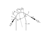
- the contact length in the longitudinal direction of the base film is L, and the center position of the contact length is L.
- a vertical plane perpendicular to the surface of the release member, the side where the base film approaches the release member relatively is the upstream side, and the side where the base film moves away from the release member relative to the release member.
- the contact length L [m] is in the range of 1 ⁇ 10 -5 to 1 ⁇ 10 -3 m, and the angle ( acute angle) ⁇ 1 [°], the angle (acute angle) ⁇ 2 [°] between the vertical plane and the base film located downstream of the vertical plane, the base material located upstream of the vertical plane
- the tension T 1 [N/m] applied to the film and the tension T 2 [N/m] applied to the base film on the downstream side of the vertical plane are expressed by the following formula (1). It is preferable to peel off the coating as follows.
- the contact length L is 5 ⁇ 10 ⁇ 6 m at the shortest. This was the limit of machining. Even if you try to process it to less than 5 x 10 -6 m, burrs will appear during processing , and even if you remove the generated burrs with abrasive paper or abrasive cloth, polishing marks will remain. It was not possible to produce it.
- the tension T 1 and T 2 are set large in order to satisfy the above formula (1), and the tension between the vertical surface and the base film is further increased. It is necessary to keep the angles ⁇ 1 and ⁇ 2 as small as possible. In this case, even if you try to adjust the peeling conditions of the film according to the properties of the film to be peeled off, the range that can be adjusted in the above formula (1) will be narrowed, so the properties that are relatively easy to peel off will be narrowed. It was possible to remove the film only from the following films.
- the coating peeling method of the present invention when a rigid body such as a scraper or a metal plate with a tip shape as shown in FIG. Of the two surfaces including the ridge line where the peeling begins, the surface facing the base film before contacting the ridge line (hereinafter sometimes referred to as the upstream side r1 of the peeling member) and the surface before contacting the ridge line It is preferable to peel off the film while setting the angle ⁇ 3 between the film and the base film to be 5° or more. When the angle is less than 5°, the peeled film (hereinafter referred to as peeled material) is formed between the base film that approaches the peeling member relatively and the upstream side surface r1 of the peeling member. ) was confirmed to accumulate.
- peeled material peeled material
- the coating When the coating is continuously peeled off, a part of the deposited peeled material overflows to the edge of the base film in the width direction, and the side surface of the edge of the base film in the width direction is spilled out. In rare cases, it adhered to the back side of the base film. On the other hand, it was confirmed that by setting the angle ⁇ 3 to 5° or more, the amount of deposited peeling material was significantly reduced. When the angle is 5° or more, the peeled material does not flow along the upstream side surface r1 of the peeling member and overflow in the transverse direction of the base film, and can be stably and continuously. The film could be peeled off.
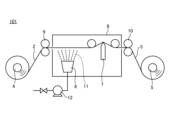
- FIG. 1 is a schematic diagram of a film stripping device 101 according to an embodiment of the present invention.
- the film peeling device 101 includes an unwinding device 4 that unwinds a base film 2 having a film, and a winding device 5 that winds up the base film 3 after the film has been peeled off.
- a film peeling device 101 includes a drive device 9 for conveying a base film 2 having a film between an unwinding device 4 and a winding device 5, and a cleaning liquid 11 for applying a cleaning liquid 11 to the film of the base film 2 having a film.
- a discharge head 6 as a cleaning liquid applying mechanism for cleaning
- a peeling member 7 for peeling off both the coating of the base film 2 having a coating and the cleaning liquid 11, and a drive for transporting the base film 3 after the coating has been peeled off.
- a device 10 is provided.
- the cleaning liquid application mechanism also includes a liquid feeding pump 12 for feeding the cleaning liquid 11 to the ejection head 6, and a tank (not shown) for storing the cleaning liquid.
- the base film is transported by the drive devices 9 and 10, and the base film moves with respect to the peeling member 7 in its longitudinal direction. Further, it is preferable that the drive devices 9 and 10 have a structure that can cut tension in order to stably transport the base film. When tension cutting is performed using a suction roll, a part of the coating on the base film 2 that has a coating may be sucked, which may cause trouble. configuration is more preferably used.
- the drives 9, 10 also function as tensioning mechanisms.
- the rotational speed of each of the drive rolls of the drive devices 9 and 10 can be set individually, and by controlling the rotation speed, the rotation speed of the drive rolls of each of the drive devices 9 and 10 can be set, and by controlling the rotation speed, It is preferable to include a mechanism (tension control mechanism) that can control the tension applied in the longitudinal direction of the film.
- the invention is not limited to this, as long as it has a mechanism that can control the tension applied to the base film in the longitudinal direction of the base film.
- a tension meter (not shown) is installed between the drive device 9 and the peeling member 7, or between the peeling member 7 and the drive device 10, or both, so that a predetermined tension is achieved.
- a peeling member is provided so that the coating can be peeled off at a constant speed even when the base film 2 having the coating is intermittently conveyed in order to deal with troubles during operation that occur in step 101 or for inspection before peeling off the coating.
- An accumulator (not shown) may be provided closer to the unwinding device 4 than 7.
- a dancer roll (not shown) may be provided between the drive device 9 and the drive device 10 to reduce tension fluctuations that occur when changing the conveyance speed, but it is possible to Any means that can reduce fluctuations are not limited to these.
- the base film moves in the longitudinal direction with respect to the peeling member 7.
- the mechanism may be provided with a mechanism for moving the peeling member 7 relative to the stationary base film, or it may be a mechanism for moving both the peeling member 7 and the base film, both in the same direction or in different directions. It may also be a mechanism that moves.
- the ejection head 6 and the peeling member 7, which are part of the cleaning liquid application mechanism, are surrounded by a booth 8.
- the ejection head 6 only needs to be able to eject the cleaning liquid 11 and apply it to the coating surface of the base film 2 having a coating, and examples thereof include a slit nozzle and a spray nozzle, but the invention is not limited thereto.
- the amount of cleaning liquid 11 applied to the coating surface of the base film 2 having a coating is preferably in the range of 3 to 650 ml/m 2 so as to sufficiently dissolve the coating containing the water-soluble resin.
- the amount of cleaning liquid 11 applied may be controlled by using a metering pump as the liquid pump 12, or by installing a flow meter (not shown) between the liquid feeding pump 12 and the discharge nozzle 6, and controlling the amount of the cleaning liquid 11. Control may be performed by feeding back the instruction value. Alternatively, the discharged cleaning liquid 11 may be collected, the amount of application may be determined from its mass, and the amount of application may be controlled by feeding back to the liquid feeding pump.
- the ejection head 6 and the peeling device 7 may be installed facing the coating surface of the base film 2 having a coating.
- the coating is laminated on the bottom side of the base film 2
- the discharge head 6 and the peeling device 7 are installed so as to face the bottom side of the base film 2 on which the coating is laminated.
- the installation is not limited to the lower surface side of the film 2.
- the unwinding direction of the base film 2 having a coating is changed so that the coating of the base film 2 wound into a roll can be applied to either the inside or outside of the roll. It is more preferable that the unwinding device has a mechanism that can handle both upward and downward feeding so that the coating surface of the base film 2 can be conveyed facing the ejection head 6 and the peeling device 7.
- the ejection head 6 is preferably capable of ejecting the heated cleaning liquid 11 in order to quickly dissolve the water-soluble resin contained in the coating.
- the cleaning liquid 11 may be heated by providing the ejection head 6 with a heat source such as a cartridge heater, or by heating a tank (not shown) storing the cleaning liquid, but any means that can heat the cleaning liquid 11 may be used. However, it is not limited to these.
- the cleaning liquid 11 may be ejected from the ejection head 6 in the form of steam.
- the material of the ejection head 6 is preferably heat resistant in order to eject the heated cleaning liquid 11, and metal or heat resistant resin is preferably used.
- FIG. 2 is a schematic cross-sectional view of the peeling member 7 of the first embodiment in the film peeling apparatus 101.
- the peeling member 7 directly contacts the coating surface of the base film 2 having a coating, and the angle formed by the base film through the peeling member 7, that is, the base film 3 from which the coating has been peeled and the base film before the coating is peeled. 2 and the angle ( ⁇ 1 + ⁇ 2 ) is in the range of 20 to 150°.
- the peeling member 7 bends or vibrates when peeling the coating from the base film 2, or when the tension applied to the base film 2 is high. may be deformed or damaged, causing problems in peeling off the coating.
- the force with which the peeling member 7 is pressed against the base film 2 becomes weaker.
- the force with which the peeling member 7 is pressed against the base film 2 becomes weaker.
- the force that presses the peeling member 7 against the base film 2 increases. If the amount is insufficient, the coating may not be peeled off and a portion of the coating may remain on the base film.
- the tension in the longitudinal direction of the base film (T 1 , T 2 ) applied to the base film is controlled by the aforementioned tension control mechanism, and the tension can be adjusted in the range of 10 to 1000 N/m. preferable.
- the applied tension and the angle formed by the base film through the peeling member 7 may be adjusted depending on the properties of the base film 2 having the film to be peeled off. The smaller the angle, the more strongly the base film 2 having the coating can be pressed against the peeling member 7, and therefore the coating can be peeled off more reliably. However, if the pressing force is too strong, it may exceed the breaking strength of the base film and the base film may break.
- the inventors found that by setting the tension to 1000 N/m or less, even when the angle formed by the base film was made small, the film could be continuously formed without breaking the base film. It was confirmed that peeling could be performed. If the tension exceeds 1000 N/m, the base film may occasionally break due to foreign matter attached to the tip of the peeling member 7 or slight burrs generated during processing when manufacturing the peeling member 7. I also checked the situation. On the other hand, the lower the tension, the smaller the force with which the peeling member 7 is pressed against the base film, making it more difficult to peel off the film.
- the lower limit of the tension is preferably 50 N/m or more, more preferably 100 N/m or more.
- the peeling member 7 in the peeling device 101 of the present invention is provided so as to be in direct contact with the coating surface of the base film 2 having a coating. Adjust so that the angle ( ⁇ 1 + ⁇ 2 ) is in the range of 20 to 150°. In this state, it is preferable that the contact length L of the peeling member 7 in the longitudinal direction of the base film in the range in which it contacts the coating surface is in the range of 1 ⁇ 10 ⁇ 5 to 1 ⁇ 10 ⁇ 3 m. At this time, in order to strengthen the force of pressing the peeling member 7 against the base film, the shorter the contact length L, the better.
- the limit of the contact length L that could be manufactured without causing warping or burrs during processing was 5 ⁇ 10 ⁇ 6 m.
- the contact length L is 5 ⁇ 10 ⁇ 6 m
- the tip of the peeling member 7 is It was sometimes deformed. Therefore, it has been found that in order to prevent the tip of the peeling member 7 from being deformed even under various conditions, it is more preferable that the contact length L is 1 ⁇ 10 ⁇ 5 m or more.
- the contact length L is long, the force for pressing the peeling member 7 against the base film is dispersed over a wide area by the contact length L, making it difficult to peel off the coating.
- the inventors found that by setting the contact length L to 1 ⁇ 10 -3 m or less, even if the properties of the target film change, the amount of cleaning liquid 11 applied and the amount applied to the base film can be adjusted. By adjusting the tension and the angle formed between the base films via the peeling member 7, the film could be peeled off. If the contact length L exceeds 1 ⁇ 10 ⁇ 3 m, the force for pressing the peeling member 7 against the base film is dispersed and becomes smaller, making it difficult to peel the film stably. Some film remained.
- FIG. 3 is a schematic diagram of the second peeling member 13 in the film peeling apparatus 101 of the present invention.
- the contact length L in the longitudinal direction of the base film in the range that contacts the coating surface of the peeling member 13 includes the case where the tip of the peeling member 13 is an arc.
- FIG. 4 is a schematic diagram of the third peeling member 14 in the film peeling apparatus 101 of the present invention.
- the contact length L corresponds to the sum of L 1 , L 2 , and L 3 .
- the sum of the contact lengths L 1 , L 2 , and L 3 is preferably in the range of 1 ⁇ 10 ⁇ 5 to 1 ⁇ 10 ⁇ 3 m.
- the booth 8 of the stripping device 101 is designed to prevent the cleaning liquid 11 from scattering around, and to prevent the temperature of the cleaning liquid 11 from decreasing when the cleaning liquid 11 is heated. It is provided so as to surround up to the peeling device 7.
- the material of the booth 8 is preferably heat resistant because the inside of the booth 8 becomes high temperature, and metal, glass, or the like is preferably used.
- a drying device may be provided between the two.
- the drying device may be provided before winding up, and may be provided either before or after the drive device 10.
- an inspection machine (not shown) may be installed in front of the winding device 5 to detect coating residue and environmental foreign matter attached during the process. good.
- the inspection device may be selected according to the properties of the base film 3, and an inspection device using transmitted light or reflected light is preferably used.
- a marking device (not shown) may be provided between the inspection device and the winding device 5 for recording the position of the coating residue detected by the inspection device or the environmental foreign matter attached during the process.
- the marking method by the marking device may be any method, such as a pen, a sticker, or a laser, as long as the position of the detection target can be marked.
- the base film having a coating may be in the form of cut sheets, but it is particularly preferably a base film having a coating wound into a roll.
- a base film having a film wound into a roll By unwinding a base film having a film wound into a roll, peeling the film using the film peeling device of the present invention, and winding up the base film after the film has been peeled off, the film can be continuously and efficiently processed. It is possible to perform coating removal treatment.
- the substrate film 2 having the coating is disposed between the unwinding device 4 and the drive device 9.
- a device may be provided to expose the layer containing a large amount of water-soluble resin in the coating.
- the coating of the base film having a coating is a thermosetting silicone resin compound having dimethylsiloxane as its main skeleton
- the base film having the coating is suitable as a mold release film for processes due to its surface free energy characteristics. Specifically, it is used as a release film for providing a release object on the coating of a base film having a coating and then extracting the release object in a desired shape.
- the base film having the coating may have a release material remaining on the surface of the coating, so the unwinding device 4 and the drive device 9 It is preferable that a device for exposing the coating surface of the base film having the coating is provided between the two and exposing the coating surface of the base film having the coating.
- the device for exposing the coating surface may be a contact type or a non-contact type, and is appropriately selected depending on the remaining state of the object to be released.
- the material to be released is selected as appropriate depending on the characteristics of the film, but main materials include inorganic materials such as metals provided by vapor deposition, adhesives made of organic materials such as acrylic materials provided by coating, and barium titanate.
- inorganic materials such as metals provided by vapor deposition
- adhesives made of organic materials such as acrylic materials provided by coating
- barium titanate An example is a ceramic green sheet as a component.
- the water-soluble resin can be dissolved from the surface of a film having a film using a small amount of cleaning liquid, and the film can be efficiently and reliably peeled off. be able to.
- high purity resin chips free of foreign matter can be obtained at low cost without significantly increasing the environmental load, so the recycled film can be stabilized. It is possible to form a film by
- ⁇ Base film with coating> A coated film shown below was produced.
- ⁇ Film with coating> A film of polyvinyl alcohol resin as a water-soluble resin was formed to a thickness of 0.1 ⁇ m on one side of a base film of polyethylene terephthalate having a thickness of 30 ⁇ m and a width of 100 mm.
- a film of a curable silicone resin as a release component was formed thereon to a thickness of 0.1 ⁇ m as follows, with reference to the coating material described in JP-A-2015-189226.
- ⁇ Thermosetting silicone manufactured by Shin-Etsu Chemical Co., Ltd., trade name "KS-847T”: 100 parts by mass
- ⁇ Platinum catalyst manufactured by Shin-Etsu Chemical Co., Ltd., trade name "CAT-PL-50T”: 3 parts by mass
- KS-847T 100 parts by mass
- CAT-PL-50T 3 parts by mass
- it was applied onto the polyvinyl alcohol resin film using a bar coater and dried in an oven at 90° C. for 20 seconds to form a release component film, thereby obtaining a film with a film.
- Peelability of coating Peeling was evaluated using a commercially available dyne pen (surface energy: 30, 70 mN/m) in the following manner. When drawing with a dyne pen on the surface of a sample under a room temperature of 23° C. and maintaining that state for 4 seconds or more, it was determined that the surface energy of the sample surface was higher than the surface energy of the dyne pen. If the film of the release component of the coated film remains on the surface, the surface energy of both of these is less than 30 mN/m, so the reagent of any dyne pen will be repelled by the sample surface and the drawing will not be maintained.
- the surface energy is 70 mN/m or more, so any dyne pen can maintain drawing.
- the surface energy is 43.8 mN/m, so the dyne pen of 30 mN/m The drawing is maintained, but the drawing of the 70 mN/m dyne pen cannot be maintained.
- the mold release component of the membrane-coated film If the coating of the mold release component of the membrane-coated film remains on the surface, the mold release component will mix into the recycled resin chips, causing the recycled resin chips to become colored (yellowing) and generate foreign matter. The quality of the chip deteriorates and it becomes unusable. Although the film of the mold release component has been peeled off, if some of the water-soluble polyvinyl alcohol resin film remains, the recycled resin chip will be slightly colored (yellowing) and the quality will be poor compared to the quality of the raw material. Although it is slightly inferior, it is within the practical range. If both the release component coating and the water-soluble polyvinyl alcohol resin coating are peeled off, the recycled resin chip will have good quality.
- Example 1 The coated film was set in the unwinding device 4 of the peeling device 101 shown in FIG. A spray nozzle (two-fluid system) was used for the discharge head 6 that discharges the cleaning liquid 11.
- the cleaning solution was hot water at 60° C., and the discharge amount was adjusted to 3 to 650 ml per 1 m 2 of surface area of the coating using a diaphragm pump, and the solution was directly applied to the coating.
- the peeling member 7 was a stainless steel plate with a tip shaped as shown in FIG. 2, and the width of the tip in the substrate transport direction was 1.0 ⁇ 10 ⁇ 5 m.
- the peeling member 7 was arranged so that the angle ( ⁇ 1 + ⁇ 2 ) between the base films through the peeling member 7 was 90° ( ⁇ 1 : 45°, ⁇ 2 : 45°). As a result, it was confirmed that the length L where the base film and the tip of the plate directly contact each other in the transport direction was 1.0 ⁇ 10 ⁇ 5 m.
- the ejection head 6 and the peeling member 7 were arranged so that the base film reached the peeling member 7 one second after being applied with hot water by the ejection head 6.
- the film was peeled off by conveying the base film while applying a tension of 10 N/m from both directions in the longitudinal direction of the base film. Furthermore, in the same apparatus configuration, the coating was peeled at tensions of 500 N/m and 1000 N/m.
- the base film 3 was taken up with the winding device 5 and the film was peeled off, and the state of peeling of the film was confirmed using a dyne pen. It was confirmed that when the amount was adjusted to a range of 650 ml/m 2 , both the coatings of the curable silicone resin as the release component and the water-soluble polyvinyl alcohol resin could be peeled off. Under the condition of a tension of 500 N/m, if the amount of water applied was adjusted to a range of 10 to 650 ml/m 2 , both the curable silicone resin and water-soluble polyvinyl alcohol resin coatings of the release component could be peeled off. .
- Example 2 The coated film was set in the unwinding device 4 of the peeling device 101 shown in FIG.
- the amount of water applied to the film was 100 ml/m 2 .
- the angle ( ⁇ 1 + ⁇ 2 ) formed by the base film via the peeling member 7 was 20°, and the tension was 500 N/m.
- the film was otherwise peeled off in the same manner as in Example 1. Also, using the same device components, it was modified so that the angle ( ⁇ 1 + ⁇ 2 ) could be changed, and the angle ( ⁇ 1 + ⁇ 2 ) was changed to 45° ( ⁇ 1 : 22.5°, ⁇ 2 : 22.5°).
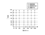
- FIG. 6 shows whether or not the film can be coated at each level.
- " ⁇ ” in the figure indicates conditions under which it was confirmed that both the curable silicone resin and water-soluble polyvinyl alcohol resin coatings of the mold release component could be peeled off.
- " ⁇ ” in the figure indicates a condition in which the curable silicone resin was peeled off, but a portion of the polyvinyl alcohol resin remained on the surface of the base film.
- the "x" in the figure indicates a condition in which both the curable silicone resin and the polyvinyl alcohol resin partially remained on the surface of the base film. From this result, it was confirmed that the more obtuse the angle between the film-releasable base films and the lower the applied tension, the more the film remained unremoved.
- Example 3 The coated film was set in the unwinding device 4 of the peeling device 101 shown in FIG.
- a plurality of types of stainless steel plates having tip shapes as shown in FIG. 2 were prepared for the peeling member 7, and the length L at which the tip portion directly contacted the base film in the transport direction was changed.
- L is 1.0 ⁇ 10 ⁇ 5 , 2.5 ⁇ 10 ⁇ 5 , 5.0 ⁇ 10 ⁇ 5 , 1.0 ⁇ 10 ⁇ 4 , 2.0 ⁇ 10 ⁇ 4 , 5.0 ⁇ 10 -4 m , 7.5 ⁇ 10 ⁇ 4 m , and 1.0 ⁇ 10 ⁇ 3 m, each plate was prepared.
- the angle ( ⁇ 1 + ⁇ 2 ) formed by the base film through the peeling member 7 was varied in the range of 20° to 150°, and the tension was also varied in the range of 10 to 1000 N/m.
- the distance between the ejection head 6 and the peeling member 7 was adjusted each time so that hot water reached the peeling member 7 one second after being applied to the base film. In other respects, the coating was peeled off in the same manner as in Example 1.
- FIG. 7 shows the correlation between coating availability and ⁇ T 1 ⁇ cos( ⁇ 1 )+T 2 ⁇ cos( ⁇ 2 ) ⁇ /L at each level. Note that the meanings of each symbol in the figure are the same as in the second embodiment.
- formula (1) 1.0 ⁇ 10 6 ⁇ T 1 ⁇ cos( ⁇ 1 )+T 2 ⁇ cos( ⁇ 2 ) ⁇ /L ⁇ 2.4 ⁇ 10 8 It was confirmed that the film could be peeled off.
- ⁇ Comparative example 1> The coated film was set in the unwinding device 4 of the peeling device 101 shown in FIG. The coating was peeled off in the same manner as in Example 1, except that the discharge amount of the cleaning liquid 11 was adjusted to 2 ml per 1 m 2 of surface area of the coating.
- the base film 3 was taken up by the take-up device 5 and the coating was peeled off, and the peeling state of the coating was confirmed using a dyne pen, it was found that the releasing component, curable silicone resin, and water-soluble polyvinyl alcohol resin were mixed. It was confirmed that the coating remained in all cases. Since it was confirmed that both films remained, no further evaluation was conducted.
- ⁇ Comparative example 2> The coated film was set in the unwinding device 4 of the peeling device 101 shown in FIG. A tension of 1100 N/m was applied from both directions in the longitudinal direction of the base film. Other than that, the coating was peeled off in the same manner as in Example 1. Due to the application of high tension, corrugated iron-like wrinkles were generated in the base film in the direction of conveyance. Since the generated wrinkles passed through the peeling member 7 as they were, it was visually confirmed that the film remained at the same position in the width direction of the film as the wrinkles occurred. The base film 3 from which the film had been peeled off after being wound up by the winding device 5 was taken and the state of peeling of the film was confirmed using a dyne pen.
- both the curable silicone resin and water-soluble polyvinyl alcohol resin coatings remained.
- both the curable silicone resin and water-soluble polyvinyl alcohol resin coatings of the release component could be peeled off at positions where wrinkles were not generated. Since it was difficult to extract from the collected base film 3 only the areas where any film was peeled off, no further evaluation was carried out.
- the base film having a film that can be applied to the method and device for peeling a film from a base film having a film of the present invention is not limited to a film having a film containing a water-soluble resin on one side of the base film; Any recyclable resin film, paper film, or metal film having a coating including a soluble resin layer may be used.
Landscapes
- Engineering & Computer Science (AREA)
- Chemical & Material Sciences (AREA)
- Life Sciences & Earth Sciences (AREA)
- Mechanical Engineering (AREA)
- Sustainable Development (AREA)
- Health & Medical Sciences (AREA)
- Environmental & Geological Engineering (AREA)
- Chemical Kinetics & Catalysis (AREA)
- Medicinal Chemistry (AREA)
- Polymers & Plastics (AREA)
- Organic Chemistry (AREA)
- Application Of Or Painting With Fluid Materials (AREA)
- Separation, Recovery Or Treatment Of Waste Materials Containing Plastics (AREA)
Abstract
被膜を有する基材フィルムから、洗浄液を用いて効率的、かつ確実に被膜が剥離できる被膜剥離方法、および被膜剥離装置を提供する。本発明の被膜を有する基材フィルムからの被膜剥離方法は、水溶性樹脂を含む被膜を有する被膜を有する基材フィルムから被膜を剥離する方法であって、被膜の表面に3~650ml/m2の範囲で洗浄液を付与して、次いで被膜を有する基材フィルムの被膜表面に剥離部材を直接接触させながら、当該剥離部材を介して前記基材フィルムがなす角度を20~150°の範囲として、かつ、前記基材フィルムの長手方向の少なくとも一方向に10~1000N/mの範囲で張力を付与しながら、前記剥離部材に対して前記基材フィルムを当該基材フィルムの長手方向に相対的に移動させて、洗浄液を含んだ被膜を剥離することを特徴とする。
Description
本発明は、熱可塑性樹脂フィルムの表面の被膜を効率よく除去することが可能な剥離方法および剥離装置に関する。
プラスチックは様々な分野に利用されている一方、マイクロプラスチックなど海洋汚染の原因物とされ、プラスチックによる環境負荷低減が急務となっている。
また近年、IoT(Internet of Things)の進化により、コンピュータやスマートフォンに搭載されるCPUなどの電子デバイスが増加し、それに伴い、電子デバイスを駆動するために必要な積層セラミックコンデンサー(MLCC)の数も急激に増加している。このMLCCの一般的な製造方法は、プラスチックの基材フィルム上に離型層を形成した離型フィルムをキャリアシートとして使用し、該離型フィルム上にセラミックグリーンシート層を形成する工程と、該セラミックグリーンシート層を剥離してセラミックグリーンシートとする工程がある。この工程において、セラミックシートが剥離された離型フィルムは不要物として廃棄されることとなる。
また近年、IoT(Internet of Things)の進化により、コンピュータやスマートフォンに搭載されるCPUなどの電子デバイスが増加し、それに伴い、電子デバイスを駆動するために必要な積層セラミックコンデンサー(MLCC)の数も急激に増加している。このMLCCの一般的な製造方法は、プラスチックの基材フィルム上に離型層を形成した離型フィルムをキャリアシートとして使用し、該離型フィルム上にセラミックグリーンシート層を形成する工程と、該セラミックグリーンシート層を剥離してセラミックグリーンシートとする工程がある。この工程において、セラミックシートが剥離された離型フィルムは不要物として廃棄されることとなる。
すなわち、近年のMLCC数量の急激な増加に伴う離型フィルムの廃棄物増大が環境問題になっており、プラスチックの基材フィルム再利用に向けた取り組みが活発化してきている。離型フィルムに含まれる離型層の成分は、離型性の観点から、一般的には基材フィルムを構成する成分とは異なる組成であるため、離型層が付いた離型フィルムをそのまま再溶融して再生フィルムを製膜した場合、離型層の成分が異物として存在するため、安定製膜をすることができない。
特許文献1では、離型フィルムから離型成分を除去する方法として、基材フィルムと離型層との間に水溶性樹脂層を形成した離型フィルムを使用して、温水槽に2秒以上浸漬させた後に、離型フィルム表面をブラシロールで擦過させることで離型層を剥離する方法が開示されている。
特許文献2では、コーティングによって形成された被膜を有する基材フィルムから被膜を除去する方法として、有機溶剤を貯留した溶解槽を備え、溶解槽の底部には、被膜表面に接触させることが可能なスクレーパーを設置して、搬送される被膜を有する基材フィルムから被膜を溶解、除去する装置が開示されている。
特許文献2では、コーティングによって形成された被膜を有する基材フィルムから被膜を除去する方法として、有機溶剤を貯留した溶解槽を備え、溶解槽の底部には、被膜表面に接触させることが可能なスクレーパーを設置して、搬送される被膜を有する基材フィルムから被膜を溶解、除去する装置が開示されている。
しかしながら、特許文献1に開示されている被膜の剥離方法は、温水槽内に水溶性樹脂層が溶出するため、処理時間の経過とともに温水中の樹脂濃度が上昇して、初期の剥離能力を継続して発現することができないという問題がある。樹脂濃度の上昇を抑制するために、水の供給量を増大する手法を採用した場合でも、水の供給量とともに廃水量も増大するため、洗浄コストが大幅に高くなるだけでなく、環境負荷が大きくなる、という問題がある。
また特許文献2に開示されている被膜の剥離方法は、被膜を溶解除去するために有機溶剤を用いており、特許文献1と同様に初期の剥離能力を継続して発現するために大量の有機溶剤が必要になるため、環境負荷が著しく大きくなるという問題がある。また、溶解槽の底部に設けたスクレーパーが、搬送される被膜を有する基材フィルムの被膜表面に直接接触して、被膜を掻き取る装置構成であるが、基材フィルムが液中を搬送するため、スクレーパーで被膜を掻き取る際に、被膜表面とスクレーパーとの間に有機溶剤が介在しやすく、十分な掻き取り能力を得られないことがある。掻き取り能力を改善するためには、スクレーパーを介して基材フィルムの搬送方向上流側と下流側とのフィルム面がなす角度を鋭角にしていくことが想到されるが、溶解槽を深くする必要があるため、溶解槽の容積が増大して、有機溶剤の使用量をさらに増やすこととなり、環境負荷をさらに悪化させることになる。
そこで本発明は、使用後の被膜を有する基材フィルムから再溶融しても安定して再生フィルムが製膜できる基材フィルムを得るために、基材フィルムの片面に水溶性樹脂を含む被膜を有する基材フィルムの表面から、少量の洗浄液を用いて水溶性樹脂を溶解し、効率的、かつ確実に被膜を剥離できる被膜剥離方法、および被膜剥離装置を提供する。
[1]上記課題を解決する本発明の被膜剥離方法は、水溶性樹脂を含む被膜を少なくとも片面に有する基材フィルムから当該被膜を剥離する方法であって、水を主成分とする洗浄液を前記被膜に、当該被膜の表面積1m2当たり3~650mlの範囲の量で付与し、上記洗浄液が付与された被膜の表面に剥離部材を接触させ、当該剥離部材を介して上記基材フィルムがなす角度を20~150°の範囲として、かつ、上記基材フィルムの長手方向の少なくとも一方向に10~1000N/mの範囲で張力を付与しながら、上記剥離部材に対して上記基材フィルムを当該基材フィルムの長手方向に相対的に移動させて、上記基材フィルムから上記被膜を剥離する。
[2]上記[1]の被膜剥離方法は、上記剥離部材が上記被膜の表面に接触している範囲の、上記基材フィルムの長手方向の長さを接触長さL[m]、当該接触長さの中心位置を通り上記剥離部材の表面に垂直な面を垂直面、上記剥離部材に対して上記基材フィルムが相対的に近づいてくる側を上流側、および上記剥離部材に対して上記基材フィルムが相対的に離れてゆく側を下流側として、上記接触長さLが1×10⁻⁵~1×10⁻³mの範囲であり、上記垂直面と当該垂直面よりも上流側にある上記基材フィルムとのなす角度(鋭角)θ1[°]、上記垂直面と当該垂直面よりも下流側にある上記基材フィルムとのなす角度(鋭角)θ2[°]、上記垂直面よりも上流側にある上記基材フィルムに付与される張力T1[N/m]、および上記垂直面よりも下流側にある上記基材フィルムに付与される張力T2[N/m]とが、下記式(1)を満たすことが好ましい。
式(1): 1.0×10⁶≦{T1×cos(θ1)+T2×cos(θ2)}/L≦2.4×108
式(1): 1.0×10⁶≦{T1×cos(θ1)+T2×cos(θ2)}/L≦2.4×108
[3]上記[1]または[2]の被膜剥離方法は、上記剥離部材を構成する面であって、当該剥離部材が上記被膜の表面と接触し始める稜線を挟む2つの面のうち、上記稜線に接触する前の上記基材フィルムに面する側の面と、上記稜線に接触する前の上記基材フィルムとがなす角度を5°以上にすることが好ましい。
[4]上記[1]~[3]のいずれかの被膜剥離方法は、上記被膜が硬化型シリコーン樹脂を含むことが好ましい。
[4]上記[1]~[3]のいずれかの被膜剥離方法は、上記被膜が硬化型シリコーン樹脂を含むことが好ましい。
[5]上記課題を解決する本発明の被膜剥離装置は、水溶性樹脂を含む被膜を少なくとも片面に有する基材フィルムから当該被膜を剥離するための装置であって、上記被膜に洗浄液を付与するための洗浄液付与機構と、上記洗浄液が付与された上記被膜を上記基材フィルムから剥離するための剥離部材と、上記剥離部材に対して上記基材フィルムを当該基材フィルムの長手方向に相対的に移動させるための駆動装置と、上記基材フィルムの長手方向の少なくとも一方向に張力を付与するための張力付与機構と、を備え、上記洗浄液付与機構は、上記洗浄液を上記被膜の表面積1m2当たり3~650mlの範囲の量で付与するように調整されており、上記剥離部材は、上記洗浄液が付与された被膜の表面に接触し、かつ当該剥離部材を介して上記基材フィルム同士がなす角度が20~150°の範囲となるように配置されており、上記張力付与機構は、10~1000N/mの範囲の張力を付与するように調整されている。
[6]上記[5]の被膜剥離装置は、上記剥離部材の上記被膜の表面に接触する範囲の、上記基材フィルムの長手方向の長さLが1×10⁻⁵~1×10⁻³mの範囲であることが好ましい。
[7]上記[5]または[6]の被膜剥離装置は、ロール状に巻かれた上記被膜を有する基材フィルムを巻き出すための巻出装置と、上記被膜が剥離された上記基材フィルムを巻き取るための巻取装置を備えることが好ましい。
なお、剥離部材が接触する前の基材フィルムは「被膜を有する基材フィルム」、剥離部材が接触した後の基材フィルムは「被膜が剥離された基材フィルム」であるが、上記[1]~[4]の被膜剥離方法、および上記[5]~[7]の被膜剥離装置では、特に区別することなく、どちらも「基材フィルム」としている。
[7]上記[5]または[6]の被膜剥離装置は、ロール状に巻かれた上記被膜を有する基材フィルムを巻き出すための巻出装置と、上記被膜が剥離された上記基材フィルムを巻き取るための巻取装置を備えることが好ましい。
なお、剥離部材が接触する前の基材フィルムは「被膜を有する基材フィルム」、剥離部材が接触した後の基材フィルムは「被膜が剥離された基材フィルム」であるが、上記[1]~[4]の被膜剥離方法、および上記[5]~[7]の被膜剥離装置では、特に区別することなく、どちらも「基材フィルム」としている。
本発明の被膜剥離方法および被膜剥離装置によれば、基材フィルムの片面に水溶性樹脂を含む被膜を有する基材フィルムから、少量の洗浄液で効率的かつ確実に被膜を剥離することができる。
本発明者らは、基材フィルムの片面に水溶性樹脂を含む被膜を有する被膜付きフィルムの表面から、ごく少量の洗浄液を用いて、効率的かつ確実に被膜を剥離する方法を鋭意検討した結果、次のような被膜剥離方法と被膜剥離装置を見出すに至った。
[対象となる被膜を有する基材フィルム]
本発明の被膜を有する基材フィルムからの被膜剥離方法は、基材フィルムの少なくとも片面に水溶性樹脂を含む被膜を有する基材フィルムを対象として、被膜を洗浄して基材フィルムから被膜を剥離して取り除く方法である。被膜は、基材フィルムの片面にあっても両面にあってもよく、特に限定されない。
本発明の被膜を有する基材フィルムからの被膜剥離方法は、基材フィルムの少なくとも片面に水溶性樹脂を含む被膜を有する基材フィルムを対象として、被膜を洗浄して基材フィルムから被膜を剥離して取り除く方法である。被膜は、基材フィルムの片面にあっても両面にあってもよく、特に限定されない。
対象となる被膜を有する基材フィルムは、環境への負荷等を考慮した水溶性樹脂を含む被膜に加え、他の水溶性樹脂を含む被膜を有する基材フィルムが対象となり得る。中でも水溶性樹脂として、水溶性のポリエステル系樹脂、ポリエステルウレタン系樹脂、アクリル系樹脂、エチレンアイオノマー系樹脂、ポリビニルアルコール系樹脂、ポリビニルピロリドン系樹脂、エチレン-ビニルアルコール系樹脂、でんぷんのうちの少なくとも1種を主たる成分とするものがより好ましい。
水溶性樹脂を含む被膜は、水溶性樹脂を含む単層体であっても、水溶性樹脂を含む2つ以上の層の積層体であっても、水溶性樹脂を含む層と水溶性樹脂を含まない層の積層体であってもよい。
また、被膜の一部に水溶性樹脂のほかに離型成分を含む被膜付き離型フィルムが特に好ましく、効率的に被膜剥離の効果を発現することができる。ここでいう離型成分とは、被膜表面の水に対する接触角を大きく、すなわち、被膜の表面エネルギーを小さくする成分であり、例えば、硬化型シリコーン樹脂である、ジメチルシロキサンを主骨格とする熱硬化型シリコーン樹脂化合物や、アクリロイル基あるいはメタクリロイル基を含有するオルガノポリシロキサンに光重合開始剤を配合し、UV光を照射することによって硬化させるUV硬化型シリコーン樹脂化合物、そのほか、長鎖アルキル基を有する化合物、フッ素を有する化合物が挙げられる。被膜は水溶性樹脂と離型成分とが混合されてもよいし、それぞれの層が積層されていてもよい。積層された被膜の場合には、基材フィルムの直上に水溶性樹脂を含む層、ついで最表面に離型成分を含む層が形成されていることが好ましく、離型成分には水の透過性が高いジメチルシロキサンを主骨格とする熱硬化型シリコーン樹脂化合物を用いるのが特に好ましい。
[被膜を有する基材フィルムからの被膜剥離方法]
本発明の被膜剥離方法は、上記水溶性樹脂を含む被膜を少なくとも片面に有する基材フィルムの被膜表面に、水を主成分とする洗浄液を被膜の表面積1m2あたり3~650mlの量で付与して、洗浄液が付与された被膜の表面に剥離部材を接触させるとともに、剥離部材を介して基材フィルムがなす角度を20~150°の範囲として、かつ、基材フィルムの長手方向の少なくとも一方向に10~1000N/mの範囲で張力を付与しながら、剥離部材に対して基材フィルムをその長手方向に相対的に移動させて、被膜を有する基材フィルムから被膜を除去する被膜剥離方法である。
本発明の被膜剥離方法は、上記水溶性樹脂を含む被膜を少なくとも片面に有する基材フィルムの被膜表面に、水を主成分とする洗浄液を被膜の表面積1m2あたり3~650mlの量で付与して、洗浄液が付与された被膜の表面に剥離部材を接触させるとともに、剥離部材を介して基材フィルムがなす角度を20~150°の範囲として、かつ、基材フィルムの長手方向の少なくとも一方向に10~1000N/mの範囲で張力を付与しながら、剥離部材に対して基材フィルムをその長手方向に相対的に移動させて、被膜を有する基材フィルムから被膜を除去する被膜剥離方法である。
本発明の被膜剥離方法における洗浄液を被膜表面に付与する方法は、いかなる手法でもよく、例えば、スプレーノズルを用いて洗浄液を液滴の状態で付与してもよいし、高圧洗浄機やスチーム発生装置を用いて、高圧あるいは高温の洗浄液を付与してもよい。洗浄液の付与量は、剥離対象である被膜の性状や厚みによって、適宜調整されることが好ましく、洗浄液の付与方法によって適正に管理されるのがよい。例えば、洗浄液を定量ポンプで送液することで管理したり、洗浄液が送液される流路の途中に流量計を設置したり、被膜表面に付与された洗浄液を回収して質量測定をしてもよい。あるいは、水溶性樹脂に洗浄液が含有されて質量測定が困難な場合には、被膜を有する基材フィルムと付与された洗浄液、剥離した後の被膜、これら全てを回収して、洗浄液の付与量を算出してもよい。
本発明者らが鋭意検討した結果、水溶性樹脂を含む被膜厚みを20×10-6mmから1.0mmの間とした場合、洗浄液の付与量は被膜の表面積1m2あたり3ml以上とすることで被膜剥離の効果を得られることを確認した。被膜の表面積1m2あたり3mlを下回る場合には、被膜剥離の効果が低くなる場合があることを確認しており、特に周囲環境の湿度が低い場合に洗浄液が水溶性樹脂を含む被膜を溶解あるいは膨潤させる前に、洗浄液の乾燥が進行してしまい、被膜剥離の効果を得ることができないことがある。一方で洗浄液の付与量は多いほど、水溶性樹脂を含む被膜をより確実に溶解あるいは膨潤させることができて、被膜を剥離する効果が向上する。特に水溶性樹脂を含む被膜厚みが1.0mmの場合においても、被膜の表面積1m2あたり650mlの洗浄液を被膜表面に付与することで、被膜剥離の効果が得られることを確認した。
本発明の被膜剥離方法に用いる洗浄液は、水溶性樹脂を溶解しうる溶媒であれば、いかなる溶媒でもその効果を発現するが、環境負荷を低減するためには、水を使用するのが好ましい。また水を主成分として界面活性剤などを添加することで、洗浄液と被膜表面との濡れ性を改善して、被膜全体に洗浄液を行き渡らせやすくしてもよい。
本発明の被膜剥離方法における剥離部材は、スクレーパーや布帛、金属プレート、回転させたブラシロールなどが例示されるがこれらに限定されるものではなく、被膜を有する基材フィルムに直接接触して、物理的に被膜を剥離することができれば、いかなる手段でもよい。また剥離部材は、基材フィルムの被膜を有する面に対して、剥離部材を押し込むように直接接触させておくことが好ましく、剥離部材によって基材フィルムを屈曲あるいは湾曲させた状態として、それを維持したまま、剥離部材に対して基材フィルムをその長手方向に相対的に移動させることで基材フィルムから被膜を剥離することができる。上記の屈曲あるいは湾曲させた状態の基材フィルムは、剥離部材を介して基材フィルムがなす角度を20~150°の範囲とし、長手方向の少なくとも一方向に10~1000N/mの範囲で張力を付与していることが好ましい。これにより、基材フィルムの被膜表面に対して剥離部材を強く押し付けることができるため、洗浄液によって溶解あるいは膨潤した被膜を効率的かつ確実に剥離することが可能となる。従って、剥離部材は被膜を有する基材フィルムに接触する範囲が狭いほど、局所的に、より強く基材フィルムの被膜表面に対して剥離部材を強く押し付けることができるため好ましく、上記に例示した剥離部材のうち、スクレーパーや金属プレートの角部などが好適に用いられる。
剥離部材を介した基材フィルムのなす角度を20°未満とした場合には、剥離部材を設置するスペースが非常に狭くなるため、現実的ではない。一方で当該角度を150°より大きくした場合には、基材フィルムの被膜表面に対して剥離部材を押し付ける力が弱くなるものの、一部の剥離が容易な被膜性状においては剥離可能であることが確認できた。しかしながら、基材フィルムと剥離部材とを基材フィルムの長手方向に相対的に移動させた時に張力変動が発生した場合や剥離速度を高速化した場合に、基材フィルムと剥離部材との間に容易に空気が同伴してしまい、被膜の一部が剥離できずにすり抜けて、基材フィルム上に残存してしまうことがあることを確認した。
基材フィルムの長手方向の少なくとも一方向に付与する張力は、10N/m以上とすることで被膜剥離の効果が発現することを確認した。付与する張力を10N/m未満として基材フィルムを搬送させた場合、低張力であるために安定搬送をすることができず、張力が大きく変動したり、搬送時に蛇行が発生したりして、被膜を剥離することができなくなる場合がある。一方で1000N/mを超える張力を付与した場合には、基材フィルムが一方向に強く引っ張られるために、基材フィルムの幅方向に複数のトタン皺が長手方向に渡って発生し、そのうちのいくつかのトタン皺が剥離部材と接触する箇所では折れ皺となり、その折れ皺の部分で被膜を剥離することができない場合がある。
本発明の被膜剥離方法は、剥離部材に対して上記の好ましい形態とした被膜を有する基材フィルムをその長手方向に相対的に移動させることで被膜を有する基材フィルムから被膜を剥離する。剥離部材に対して基材フィルムを相対的に移動する手段はいかなる手段でもよく、剥離部材を固定しておいて基材フィルムだけを搬送させてもよいし、静止している基材フィルムに対して剥離部材を走行させてもよい。あるいは、剥離部材と基材フィルムの双方が移動していてもよく、双方が同方向、あるいは異なる方向に移動していてもよい。基材フィルムを搬送させる場合には、基材フィルムに付与する張力を一定に保つのが好ましく、基材フィルムの搬送速度を変更したり、搬送停止と搬送開始とを繰り返したりする場合においても、張力を一定に保つのが好ましい。
対象とする被膜を有する基材フィルムが、基材フィルムの長手方向に渡って連続的あるいは断続的に被膜を有している場合には、基材フィルムを搬送させて、剥離部材を基材フィルムの短手方向に延在かつ固定した状態として被膜剥離を実施するのが好ましい。
特に被膜を有する基材フィルムが、基材フィルムの長手方向に断続的に被膜を有していたり、基材フィルムの長手方向に渡って、基材フィルム上に形成されている被膜の量が異なる場合には、基材フィルムの搬送速度を可変とすることで、洗浄液によって被膜が溶解、あるいは膨潤する時間を変更したり、被膜を有する箇所と剥離部材とが接触する時間を変更したりすることで、被膜剥離をより効率的に実施できるように適宜調整するのが良い。被膜が溶解、あるいは膨潤する時間、すなわち洗浄液を付与してから剥離部材で被膜を剥離するまでの時間は、被膜の性状により適正に定めることが好ましいが、装置サイズ等を鑑み、0.05~10秒となるようにすることが好ましい。
特に被膜を有する基材フィルムが、基材フィルムの長手方向に断続的に被膜を有していたり、基材フィルムの長手方向に渡って、基材フィルム上に形成されている被膜の量が異なる場合には、基材フィルムの搬送速度を可変とすることで、洗浄液によって被膜が溶解、あるいは膨潤する時間を変更したり、被膜を有する箇所と剥離部材とが接触する時間を変更したりすることで、被膜剥離をより効率的に実施できるように適宜調整するのが良い。被膜が溶解、あるいは膨潤する時間、すなわち洗浄液を付与してから剥離部材で被膜を剥離するまでの時間は、被膜の性状により適正に定めることが好ましいが、装置サイズ等を鑑み、0.05~10秒となるようにすることが好ましい。
また、被膜を有する基材フィルムが、基材フィルムの長手方向に一定の間隔をおいて被膜を有している場合には、基材フィルムを一定長さだけ搬送した後に、搬送を停止あるいは搬送速度を変更して、剥離部材を基材フィルムの被膜を有している箇所に対して相対的に移動させることで被膜剥離を実施してもよく、被膜を剥離した後は、再び搬送を開始したり、搬送速度を元に戻したりすることで、高効率かつ確実に被膜剥離をすることができる場合がある。また被膜剥離の途中で搬送を停止あるいは搬送速度を変更することで、その間に被膜を剥離した後の基材フィルムを確認して、被膜が残存していないか、検査確認をするのが良い。上記検査の方法は被膜の残存を検出できればいかなる手段でもよい。
本発明の被膜剥離方法では、剥離部材が被膜を有する基材フィルムの被膜表面に接触している範囲のうち、基材フィルムの長手方向の接触長さをLとし、当該接触長さの中心位置を通り剥離部材の表面に垂直な垂直面、剥離部材に対して基材フィルムが相対的に近づいてくる側を上流側、および剥離部材に対して基材フィルムが相対的に離れてゆく側を下流側として、接触長さL[m]が1×10⁻⁵~1×10⁻³mの範囲であり、上記垂直面と当該垂直面よりも上流側にある基材フィルムとのなす角度(鋭角)θ1[°]、上記垂直面と当該垂直面よりも下流側にある前記前記基材フィルムとのなす角度(鋭角)θ2[°]、上記垂直面よりも上流側にある基材フィルムに付与される張力T1[N/m]、および上記垂直面よりも下流側にある上記基材フィルムに付与される張力T2[N/m]とが、下記式(1)となるように被膜を剥離することが好ましい。
式(1): 1.0×10⁶≦{T1×cos(θ1)+T2×cos(θ2)}/L≦2.4×108
式(1): 1.0×10⁶≦{T1×cos(θ1)+T2×cos(θ2)}/L≦2.4×108
上記接触長さLは短いほど、剥離部材を基材フィルムの被膜表面に強く接触させることができるが、発明者らが鋭意検討した結果、接触長さLは最短で5×10⁻⁶mが機械加工の限界であった。5×10⁻⁶m未満に加工しようとしても、加工時にバリが出たり、発生したバリを研磨紙や研磨布で除去したとしても、研磨痕が残存してしまい、5×10⁻⁶m未満で製作することは出来なかった。一方で接触長さLを1×10⁻³mより大きくした場合には、上記式(1)を満たすために、張力T1やT2を大きく設定して、さらに上記垂直面と基材フィルムとがなす角度θ1とθ2はできるだけ小さくしておく必要がある。この場合に、剥離の対象となる被膜の性状に合わせて被膜の剥離条件を調整しようとしても、上記式(1)の中で調整できる範囲が狭くなってしまうため、比較的剥離が容易な性状の被膜に対してのみ被膜剥離が可能であった。
本発明の被膜剥離方法では、剥離部材として図2に示すような先端形状のスクレーパーや金属プレートなどの剛体を用いた場合、剥離部材を構成する面であって、当該剥離部材が被膜表面と接触し始める稜線を含む2つの面のうち、稜線に接触する前の基材フィルムに面する側の面(以下、剥離部材の上流側面r1と称することがある)と、稜線に接触する前の基材フィルムとがなす角度θ3を5°以上として被膜を剥離するのが好ましい。当該角度を5°未満にした場合には、上記剥離部材に対して相対的に近づいてくる基材フィルムと、剥離部材の上流側面r1との間に剥離した後の被膜(以下、剥離物)が堆積することを確認した。連続で被膜の剥離を実施した際に、堆積した剥離物の一部が基材フィルムの短手方向の端部に溢れ出るようにして流出して、基材フィルムの短手方向端部の側面や基材フィルムの裏面に付着してしまうことが稀にあった。一方で角度θ3を5°以上にすることで、堆積する剥離物が顕著に減少することを確認した。5°以上にした場合には、剥離部材の上流側面r1に沿って剥離物が流動して、基材フィルムの短手方向に溢れ出るような現象が発生せず、安定して連続的に被膜を剥離することができた。
[被膜を有する基材フィルムの被膜剥離装置]
本発明の被膜剥離装置の望ましい実施形態について、図面に基づいて説明する。なお、以下の説明は本発明に係る実施形態の1つを例示するものであり、これに限定されるものではなく、本発明の趣旨を逸脱しない範囲で種々の変更が可能である。
本発明の被膜剥離装置の望ましい実施形態について、図面に基づいて説明する。なお、以下の説明は本発明に係る実施形態の1つを例示するものであり、これに限定されるものではなく、本発明の趣旨を逸脱しない範囲で種々の変更が可能である。
図1は、本発明の一実施形態の被膜剥離装置101の概略図である。被膜剥離装置101は、被膜を有する基材フィルム2を巻き出す巻出装置4と被膜を剥離した後の基材フィルム3を巻き取る巻取装置5を備えている。被膜剥離装置101は、巻出装置4と巻取装置5との間に、被膜を有する基材フィルム2を搬送するための駆動装置9、洗浄液11を被膜を有する基材フィルム2の被膜に付与するための洗浄液付与機構としての吐出ヘッド6、被膜を有する基材フィルム2の被膜と洗浄液11をともに剥離するための剥離部材7、被膜を剥離した後の基材フィルム3を搬送するための駆動装置10を備えている。なお、洗浄液付与機構は、上記吐出ヘッド6に加えて、吐出ヘッド6に洗浄液11を送液するための送液ポンプ12、洗浄液を貯留しておくタンク(図示しない)も備えている。
基材フィルムは駆動装置9、10によって搬送されて、剥離部材7に対して基材フィルムがその長手方向に移動することになる。また駆動装置9、10は、基材フィルムを安定して搬送させるために、張力カットできる構成で有ることが好ましい。サクションロールでテンションカットする場合には、被膜を有する基材フィルム2の被膜の一部が吸引されたりして、トラブルの原因となることがあるため、金属製の駆動ロールとゴムロールでニップされた構成がより好適に用いられる。駆動装置9、10は、張力付与機構としても機能する。さらに駆動装置9、10それぞれの駆動ロールは個別に回転速度の設定を可能として、その回転速度を制御することで駆動装置9と駆動装置10との間にある基材フィルムに対して、基材フィルムの長手方向に付与する張力を制御できる機構(張力制御機構)を備えていることが好ましい。基材フィルムに対して基材フィルムの長手方向に付与する張力を制御できる機構を備えていれば、これに限定されない。張力を制御するために、駆動装置9と剥離部材7との間、あるいは剥離部材7と駆動装置10との間、またはその両方に張力計(図示しない)を設置して、所定の張力になるように駆動装置9、10の駆動ロールの回転速度にフィードバックするのが良い。また、被膜を有する基材フィルム2を巻出装置4から巻き出す速度を可変にして、巻出装置4にセットするロール状に巻かれた被膜を有する基材フィルム2の交換や、被膜剥離装置101で発生した運転中トラブルの対処、あるいは被膜を剥離する前の検査などによって、被膜を有する基材フィルム2を間欠的に搬送しても、一定速度で被膜の剥離ができるように、剥離部材7よりも巻出装置4側にアキュームレータ(図示しない)を設けてもよい。また、搬送速度を変更した際に生じる張力変動を低減するためのダンサーロール(図示しない)を駆動装置9と駆動装置10との間に設けてもよいが、搬送速度を可変にして、かつ張力変動を低減できる手段であれば、これらに限定されない。
なお、本実施形態においては、駆動装置9、10によって基材フィルムが搬送されているので、剥離部材7に対して基材フィルムがその長手方向に移動することになるが、剥離部材7に対して基材フィルムがその長手方向に相対的に移動できるのであれば、駆動装置9、10によって基材フィルムを搬送する機構に限定する必要はない。静止している基材フィルムに対して剥離部材7を走行させる機構を備えていてもよく、あるいは、剥離部材7と基材フィルムの双方を移動させる機構でもよく、双方が同方向、あるいは異なる方向に移動する機構でもよい。
また洗浄液付与機構の一部である吐出ヘッド6と剥離部材7はブース8で囲まれている。吐出ヘッド6は、洗浄液11を吐出して、被膜を有する基材フィルム2の被膜表面に付与できればよく、例えばスリットノズルやスプレーノズルなどが例示されるが、その限りではない。被膜を有する基材フィルム2の被膜表面に付与する洗浄液11の量は、水溶性樹脂を含む被膜を十分に溶解しうるように、3~650ml/m2の範囲にできることが好ましい。被膜を剥離するのに必要な量の洗浄液11を被膜を有する基材フィルム2の被膜表面に付与できるように、吐出ヘッド6と送液ポンプ12の仕様を確定し、調整するのがよい。洗浄液11の付与量は、送液ポンプ12に定量ポンプを用いることで制御してもよいし、送液ポンプ12と吐出ノズル6との間に流量計(図示しない)を設置し、流量計の指示値をフィードバックすることで制御してもよい。あるいは、吐出した洗浄液11を回収して、その質量から付与量を把握し、送液ポンプにフィードバックして付与量を制御してもよい。
吐出ヘッド6と剥離機器7は被膜を有する基材フィルム2の被膜表面に対向して設置してあればよい。図1では、被膜は基材フィルム2の下面側に積層され、被膜が積層された基材フィルム2の下面側に対向するように吐出ヘッド6および剥離機器7を設置しているが、基材フィルム2下面側への設置には限定されない。またロール状に巻かれた基材フィルム2の被膜がロールの内側、外側のいずれの面であっても対応できるように、被膜を有する基材フィルム2の巻出方向を切り替えて、被膜を有する基材フィルム2の被膜表面が吐出ヘッド6と剥離機器7とに対向して搬送できるよう、巻出装置が上出しと下出しのいずれにも対応できる機構であることがより好ましい。
吐出ヘッド6は、被膜に含まれる水溶性樹脂を早く溶解するために、加温した洗浄液11を吐出できることが好ましい。洗浄液11の加温は、吐出ヘッド6にカートリッジヒーターなどの熱源を備えていてもよいし、洗浄液を貯留するタンク(図示しない)を加熱しておいてもよいが、洗浄液11を加熱できればいかなる手段でもよく、これらには限定されない。被膜に含まれる水溶性樹脂をより早く溶解するためには、吐出ヘッド6から洗浄液11をスチームの状態で吐出してもよい。一般にスチームの吐出量を正確に把握するには計測が困難であるため、洗浄液11を貯留しているタンクから一定時間で減少した液量を計測することで、洗浄液11の付与量とするのがよい。
吐出ヘッド6の材質は、加温した洗浄液11を吐出するために耐熱性を有している事が好ましく、金属、あるいは耐熱性を有する樹脂が好適に用いられる。
吐出ヘッド6の材質は、加温した洗浄液11を吐出するために耐熱性を有している事が好ましく、金属、あるいは耐熱性を有する樹脂が好適に用いられる。
図2は、被膜剥離装置101における第1の実施形態の剥離部材7の概略断面図である。剥離部材7は被膜を有する基材フィルム2の被膜表面に直接接触し、剥離部材7を介して基材フィルムがなす角度、すなわち被膜が剥離された基材フィルム3と被膜剥離前の基材フィルム2とがなす角度(θ1+θ2)が20~150°の範囲となるように設置されている。上記角度が20°未満の場合には、剥離部材7は、基材フィルム2から被膜を剥離する際に剥離部材7が撓ったり、振動したり、基材フィルム2に付与した張力が高い場合には変形したり、破損したりして、被膜の剥離に不具合が生じることがある。また、上記角度を150°より大きくした場合には、基材フィルム2に対して剥離部材7を押し付ける力が弱くなる。その状態で基材フィルム2を搬送させて被膜の剥離を実施した場合に、基材フィルム2に付与した張力が僅かに変動しただけで、基材フィルム2に対して剥離部材7を押し付ける力が不足してしまい、被膜を剥離できずに被膜の一部が基材フィルム上に残存することがある。
また基材フィルムに付与する基材フィルムの長手方向の張力(T1、T2)は、前述の張力制御機構によって制御され、その張力は10~1000N/mの範囲で調整可能であることが好ましい。剥離対象となる被膜を有する基材フィルム2の被膜の性状によって、付与する張力と剥離部材7を介して基材フィルムがなす角度とを調整すればよく、張力は高いほど、基材フィルム同士の角度は小さいほど、より強く剥離部材7に被膜を有する基材フィルム2を押し付けることができるため、被膜をより確実に剥離することが可能である。しかしながら、押し付ける力が強すぎる場合には、基材フィルムの破断強度を超過してしまい、基材フィルムが破断することがある。基材フィルムが破断した場合には、連続的に被膜の剥離を実施することができず、被膜剥離装置101の運転効率を著しく悪化させてしまう。発明者らが幾度となく検討を繰り返した結果、張力は1000N/m以下とすることで、基材フィルムがなす角度を小さくした場合においても、基材フィルムを破断させずに連続的に被膜の剥離を実施できることを確認した。張力が1000N/mを超える場合には、剥離部材7の先端に付着した異物や剥離部材7を製作する際の加工で生じた僅かなバリを基点として、稀に基材フィルムの破断が発生する様子も確認した。一方で、張力は低いほど、基材フィルムに対して剥離部材7を押し付ける力が小さくなるため、被膜を剥離しにくくなるものの、対象となる被膜が容易に剥離できる性状の被膜であれば、僅かな張力でも被膜の剥離は可能であった。しかしながら、張力を低くした場合には、基材フィルムの搬送状態が著しく悪化し、10N/m未満の低張力に設定して基材フィルムを搬送した際には、基材フィルムが搬送中に蛇行したり、基材フィルムに皺が発生したりして、基材フィルムの幅方向において剥離部材7と直接接触しない箇所が生じて、被膜の剥離を実施することが出来なかった。張力の下限は50N/m以上が好ましく、100N/m以上がより好ましい。
図2に示すように、本発明の剥離装置101における剥離部材7は、被膜を有する基材フィルム2の被膜表面に直接接触するように設けられ、当該剥離部材7を介して基材フィルムがなす角度(θ1+θ2)が20~150°の範囲となるよう調整する。この状態において、剥離部材7は、被膜表面に接触する範囲の基材フィルムの長手方向の接触長さLが1×10-5~1×10-3mの範囲であることが好ましい。この時、基材フィルムに対して剥離部材7を押し付ける力をより強くするには、接触長さLは短いほど良いため、発明者らは剥離部材7が被膜表面に接触する箇所を可能な限り鋭利にしようとした結果、加工時の反りやバリを発生させずに製作できるのは、当該接触長さLは5×10⁻⁶mが限界であった。接触長さLを5×10⁻⁶mとした場合、基材フィルムに対して剥離部材7を押し付ける力が強い条件においては、局所的に強い力が付与されるため、剥離部材7の先端が変形することがあった。従って、多様な条件下においても剥離部材7の先端が変形しないようにするには、接触長さLは1×10⁻⁵m以上とすることがより好ましいことが分かった。接触長さLが長い場合には、基材フィルムに対して剥離部材7を押し付ける力が接触長さL分だけ広域に分散されるため、被膜が剥離しにくくなる。発明者らが鋭意検討した結果、当該接触長さLは1×10-3m以下にすることで、対象となる被膜の性状が変わっても、洗浄液11の付与量と、基材フィルムに付与する張力と、剥離部材7を介して基材フィルム同士がなす角度とを調整すれば、被膜の剥離が可能であった。当該接触長さLが1×10-3mを超える場合には、基材フィルムに対して剥離部材7を押し付ける力が分散して小さくなるため、被膜を安定して剥離することが難しくなり、一部被膜が残存した。
図3は、本発明の被膜剥離装置101における第2の剥離部材13の概略図である。図3に示すように、剥離部材13の被膜表面に接触する範囲の基材フィルムの長手方向の接触長さLは、剥離部材13の先端が円弧の場合も含む。また図4は、本発明の被膜剥離装置101における第3の剥離部材14の概略図である。図4に示すように、剥離部材14の被膜表面に接触する範囲が複数面に渡る場合には、当該接触長さLはL1、L2、L3の和に相当する。剥離部材14においては、接触長さLであるL1、L2、L3の和が、1×10⁻⁵~1×10⁻³mの範囲であることが好ましい。
剥離装置101のブース8は、洗浄液11が周囲に飛散するのを防止して、かつ洗浄液11を加温した場合には、洗浄液11の温度が低下するのを防止するために、吐出ヘッド6から剥離機器7までを囲うように具備されている。ブース8の材質は、ブース8の内部が高温になるため耐熱性を有していることが好ましく、金属あるいは、ガラス等が好適に用いられる。
巻取装置5で巻き取った基材フィルム3は、再溶融した後に再生フィルムとして安定して製膜するために水分を完全に取り除いておくことがより好ましく、剥離装置7と巻取装置5との間に乾燥装置(図示しない)を設けてもよい。乾燥装置は巻取前に設けておけばよく、駆動装置10の前後いずれでもよい。
また、被膜を剥離した後の基材フィルム3の品質を確認するために、被膜の残渣や工程で付着した環境異物を検出する検査機(図示しない)を巻取装置5の前に設けてもよい。検査機は、基材フィルム3の性状に合わせて選定すればよく、透過光や反射光を用いた検査機が好適に用いられる。また、前記検査機で検出した被膜の残渣や工程で付着した環境異物の位置を記録するためのマーキング装置(図示しない)を、検査機と巻取装置5との間に設けてもよい。マーキング装置によるマーキングの方式は、ペンやシール、あるいはレーザーなど、検出対象の位置がマーキングできれば、いかなる方式でもよい。被膜の残渣や工程で付着した環境異物をマーキングしておくことで、再溶融をする前にその箇所を除去することが可能となるため、より安定して再生フィルムを製膜することができ、再生フィルムの品質低下を防ぐこともできる。
本発明の被膜剥離装置において、被膜を有する基材フィルムの形態は、裁断された枚葉状でもよいが、ロール状に巻かれた被膜を有する基材フィルムであることが特に好ましい。ロール状に巻かれた被膜を有する基材フィルムを巻き出して、本発明の被膜剥離装置により被膜を剥離し、被膜を剥離した後の基材フィルムを巻き取ることで、連続して効率的に被膜剥離の処理をすることができる。
また、被膜を有する基材フィルムの被膜表面に付与した洗浄液11によって被膜をより効率的に溶解・膨潤させるために、巻出装置4と駆動装置9との間には被膜を有する基材フィルム2の被膜のうち、水溶性樹脂を多く含む層を露出させるための機器を設けてもよい。特に、被膜を有する基材フィルムの被膜がジメチルシロキサンを主骨格とする熱硬化型シリコーン樹脂化合物である場合、被膜を有する基材フィルムはその表面自由エネルギーの特性から、工程用離型フィルムとして好適に用いられ、具体的には、被膜を有する基材フィルムの被膜上に被離型物を設けた後、該被離型物を所望の形状で抜き出すための離型フィルムとして用いられる。このような工程用の離型フィルムとして利用された後の被膜を有する基材フィルムは、被膜表面の上に被離型物が残存している場合があるため、巻出装置4と駆動装置9との間には被膜を有する基材フィルムの被膜表面を露出させるための機器を設けて、被膜を有する基材フィルムの被膜表面を露出させることが好ましい。被膜表面を露出させる機器は、接触式であっても非接触式であってもよく、被離型物の残存状態によって適宜選択される。
被離型物としては、被膜の特性によって適宜選択されるものであるが、蒸着によって設けられた金属などの無機物や、コーティングによって設けられたアクリルなどの有機物からなる粘着剤、チタン酸バリウムを主成分とするセラミックグリーンシートなどが例示できる。
以上より、本発明の被膜剥離方法、および被膜剥離装置を用いれば、被膜を有するフィルムの表面から、少量の洗浄液を用いて水溶性樹脂を溶解して、効率的、かつ確実に被膜を剥離することができる。また、本発明の被膜剥離方法、および被膜剥離装置によれば、環境負荷を著しく大きくさせることがなく、低コストで、異物の無い高純度な樹脂チップを得ることができるため、再生フィルムを安定して製膜することができる。
以下、本発明について実施例を挙げて説明するが、本発明は必ずしもこれに限定されるものではない。
<被膜を有する基材フィルム>
以下に示す、被膜付きフィルムを作製した。
<被膜付きフィルム>
ポリエチレンテレフタレートの厚み30μm、幅100mmの基材フィルムの片面に、水溶性樹脂としてポリビニルアルコール樹脂の被膜を膜厚0.1μmで形成した。
さらにその上に、離型成分の硬化型シリコーン樹脂の被膜を特開2015-189226号公報に記載の塗材を参考にして、以下のように膜厚0.1μmとなるよう形成した。
・熱硬化型シリコーン、信越化学工業社製、商品名「KS-847T」:100質量部、
・白金触媒、信越化学工業社製、商品名「CAT-PL-50T」:3質量部、
を溶剤としてのトルエンとMEKの混合液(トルエン:MEKの質量比は1:1)中に固形分が1.8質量%となるように溶解させることで調製した。次に前記ポリビニルアルコール樹脂の被膜上にバーコーターを用いて塗布し、90℃のオーブンで20秒乾燥させて離型成分の被膜を形成し、被膜付きフィルムを得た。
<剥離評価方法>
(1)被膜の剥離性
剥離の評価は、市販のダインペン(表面エネルギー:30、70mN/m)を用いて、以下の方法で測定した。室温23℃の環境下で、試料表面にダインペンで描画し、4秒以上その状態を保持する場合は、そのダインペンの表面エネルギーよりも試料表面の表面エネルギーの方が高いと判断した。被膜付きフィルムの離型成分の被膜が表面に残れば、これらの表面エネルギーはともに30mN/m未満であるため、いずれのダインペンも試料表面に試薬が弾かれて、描画を保持できない。一方、離型成分の被膜が剥離されて、水溶性のポリビニルアルコール樹脂が表出している場合には、表面エネルギーが70mN/m以上であるため、いずれのダインペンも描画を保持できる。離型成分の被膜と水溶性のポリビニルアルコール樹脂の被膜がいずれも剥離されて、ポリエチレンテレフタレートが表出している場合には、表面エネルギーが43.8mN/mであるため、30mN/mのダインペンの描画は保持するが、70mN/mのダインペンの描画は保持できない。以上の評価方法により、被膜付きフィルムの被膜が剥離できたか否かを判断した。
膜付きフィルムの離型成分の被膜が表面に残っていると、再生樹脂チップに離型成分が混入するので、再生樹脂チップが着色(黄変)したり異物も発生したりするため、再生樹脂チップの品質が悪くなり実用に耐えられない。離型成分の被膜は剥離されているが、水溶性のポリビニルアルコール樹脂の被膜が一部残っている場合には、再生樹脂チップはわずかに着色(黄変)し、原材料の品質と比べて品質がやや劣るものの実用の範囲内となる。離型成分の被膜と水溶性のポリビニルアルコール樹脂の被膜がいずれも剥離されていると、再生樹脂チップとして良好な品質となる。
(2)再生樹脂チップの品質
(i)溶融製膜性
被膜付きフィルムから、被膜を剥離した後、基材フィルムを回収する。回収した基材フィルムをクラッシャーで粉砕した後、造粒機で造粒した再生樹脂チップを、180℃で2時間乾燥した後、押出機に投入し280℃で溶融押出して、25℃に冷却したキャストドラム上でシート状に成形し、問題なくポリエチレンテレフタレートフィルムが作製できるか否かを確認する。
(ii)固有粘度
上記(i)で得られたシートの固有粘度IV(R)を測定する。固有粘度IV(R)は、オルトクロロフェノール100mlにポリエチレンテレフタレートフィルムを溶解させ(溶液濃度C=1.2g/dl)、その溶液の25℃での粘度を、オストワルド粘度計を用いて測定する。また、同様に溶媒の粘度を測定する。得られた溶液粘度、溶媒粘度を用いて、下記(a)式により、[η](dl/g)を算出し、得られた値でもって固有粘度とする。
(a)ηsp/C=[η]+K[η]2・C
(ここで、ηsp=(溶液粘度(dl/g)/溶媒粘度(dl/g))―1、Kはハギンス定数(0.343とする)である。)。
次に、被膜付きフィルムを作製する前に、あらかじめサンプリングしておいた被膜を形成する前の基材フィルムの固有粘度IV(I)を同様に測定する。
異物の混入などによって生じる樹脂チップの品質低下は、IV(R)とIV(I)の差として表れるので、下記(b)式により、ΔIVを算出し、得られた値でもって以下のように判定する。
(b)ΔIV=IV(R)-IV(I)
・固有粘度の差が0.05以下:再生樹脂チップの品質として問題ない範囲にある。
・固有粘度の差が0.05を超えて0.2未満:再生樹脂チップの品質としてやや劣るものの、実用の範囲内にある。
・固有粘度の差が0.2を超える:再生樹脂チップの品質として実用に耐えられない。
<実施例1>
被膜付きフィルムを図1に示す剥離装置101の巻出装置4にセットした。
洗浄液11を吐出する吐出ヘッド6には、スプレーノズル(2流体方式)を用いた。洗浄液は60℃の温水として、吐出量はダイヤフラムポンプを用いて、被膜の表面積1m2当たり3~650mlに調整して、被膜に直接付与した。
剥離部材7は、図2に示すような先端形状のステンレス製のプレートを用いて、その先端部の基材搬送方向における幅は1.0×10⁻⁵mとした。当該剥離部材7を介して基材フィルム同士がなす角度(θ1+θ2)は90°(θ1:45°、θ2:45°)となるように、剥離部材7を配置した。これにより、基材フィルムとプレートの先端部が搬送方向において直接接触する長さLは1.0×10⁻⁵mとなることを確認した。基材フィルムが、吐出ヘッド6で温水を付与されてから1秒後に剥離部材7に到達するように吐出ヘッド6と剥離部材7を配置した。
基材フィルムの長手方向には、両方向から10N/mの張力を付与しながら、基材フィルムを搬送させることで、被膜の剥離を実施した。また同様の装置構成において、張力を500N/m、1000N/mとして被膜の剥離を実施した。
巻取装置5で巻き取りを行い、被膜を剥離した基材フィルム3を採取して、ダインペンで被膜の剥離状態を確認したところ、張力1000N/mの条件においては、付与する水分量を3~650ml/m2の範囲に調整すれば、離型成分の硬化型シリコーン樹脂と水溶性のポリビニルアルコール樹脂の被膜がいずれも剥離できていることが確認できた。張力500N/mの条件においては、付与する水分量を10~650ml/m2の範囲に調整すれば、離型成分の硬化型シリコーン樹脂と水溶性のポリビニルアルコール樹脂の被膜がいずれも剥離できた。一方で張力10N/mの条件においては、付与する水分量を100ml/m2以上とすることで、離型成分の硬化型シリコーン樹脂と水溶性のポリビニルアルコール樹脂の被膜がいずれも剥離できていることを確認できた。
そして、被膜の剥離を確認できた基材フィルム3を回収した後、上述の(2)(i)に記載の方法でシートを形成し、ポリエチレンテレフタレートフィルムを製膜した。溶融ポリマー中に気泡やゲル等確認されず、圧力上昇などの異常も発生することなく、ポリエチレンテレフタレートフィルムを得ることができた。各水準における固有粘度の差を図5に示す。いずれの水準も固有粘度の差は0.2以下であり、実用上問題はなかった。付与する水分量が多いほど、付与する張力は高いほど、固有粘度の差は小さく、すなわち、再生樹脂チップの品質として良好になることを確認した。
そして、被膜の剥離を確認できた基材フィルム3を回収した後、上述の(2)(i)に記載の方法でシートを形成し、ポリエチレンテレフタレートフィルムを製膜した。溶融ポリマー中に気泡やゲル等確認されず、圧力上昇などの異常も発生することなく、ポリエチレンテレフタレートフィルムを得ることができた。各水準における固有粘度の差を図5に示す。いずれの水準も固有粘度の差は0.2以下であり、実用上問題はなかった。付与する水分量が多いほど、付与する張力は高いほど、固有粘度の差は小さく、すなわち、再生樹脂チップの品質として良好になることを確認した。
<実施例2>
被膜付きフィルムを図1に示す剥離装置101の巻出装置4にセットした。
被膜に付与する水分量を100ml/m2とした。さらに剥離部材7を介して基材フィルムがなす角度(θ1+θ2)は20°とし、張力は500N/mとした。その他は実施例1と同様にして被膜の剥離を実施した。また同様の装置構成機器を用いて、角度(θ1+θ2)を変更できるように改造して、角度(θ1+θ2)を45°(θ1:22.5°、θ2:22.5°)、60°(θ1:30°、θ2:30°)、90°(θ1:45°、θ2:45°)、120°(θ1:60°、θ2:60°)、150°(θ1:75°、θ2:75°)、170°(θ1:45°、θ2:45°)、また張力は両方向から10N/m、50N/m、100N/m、250N/m、500N/m、750N/m、1000N/m、とそれぞれ変化させて同様に被膜の剥離を実施した。基材フィルムに温水が付与されてから1秒後に剥離部材7に到達するように、吐出ヘッド6と剥離部材7との距離を調整した。
巻取装置5で巻き取りを行い、被膜を剥離した基材フィルム3を採取して、ダインペンで被膜の剥離状態を確認した。図6に各水準における被膜可否について示す。図中の“○”は、離型成分の硬化型シリコーン樹脂と水溶性のポリビニルアルコール樹脂の被膜がいずれも剥離できていることを確認できた条件を示している。図中の“△”は、硬化型シリコーン樹脂は剥離できているものの、基材フィルムの表面にポリビニルアルコール樹脂が一部残存していた条件を示している。図中の“×”は、基材フィルムの表面に硬化型シリコーン樹脂とポリビニルアルコール樹脂のいずれも一部残存していた条件を示している。この結果から、被膜剥離基材フィルム同士がなす角度が鈍角であるほど、また付与する張力は低いほど、被膜の剥離残りがあることを確認した。
そして、基材フィルム3を回収した後、クラッシャーで粉砕し、造粒機で樹脂チップにした。その後、押出機に投入し280℃で溶融押出して、25℃に冷却したキャストドラム上でシート状に成形し、ポリエチレンテレフタレートフィルムを作製した。図6で“×”となった条件で回収した樹脂チップでは、溶融ポリマー中にゲルが発生して、圧力上昇による装置異常のため、ポリエチレンテレフタレートフィルムを得ることができなかった。一方で“△”の条件で回収した樹脂チップでは、溶融ポリマー中に気泡やゲル等確認されず、圧力上昇などの異常も発生することなく、ポリエチレンテレフタレートフィルムを得ることができた。その後、固有粘度の差を確認したところ、いずれの条件においても0.05を超えて0.2未満の範囲になっており、再生樹脂チップの品質としてやや劣るものの、実用の範囲内にあることが確認できた。“○”の条件で回収した樹脂チップでは、安定してポリエチレンテレフタレートフィルムを得ることができて、固有粘度の差も0.05以下であり、再生樹脂チップの品質として問題ない範囲にあることを確認した。
<実施例3>
被膜付きフィルムを図1に示す剥離装置101の巻出装置4にセットした。
剥離部材7には図2に示すような先端形状のステンレス製のプレートを複数種類準備して、その先端部と基材フィルムとが搬送方向において直接接触する長さLを変更した。具体的にLは1.0×10⁻⁵、2.5×10⁻⁵、5.0×10⁻⁵、1.0×10⁻⁴、2.0×10⁻⁴、5.0×10⁻⁴、7.5×10⁻⁴、1.0×10⁻³mとなるように各プレートを準備した。剥離部材7を介して基材フィルムがなす角度(θ1+θ2)は20°~150°の範囲で変更し、張力も10~1000N/mの範囲で変更した。吐出ヘッド6と剥離部材7との距離は、基材フィルムに温水が付与されてから1秒後に剥離部材7に到達するように、その都度調整した。その他は、実施例1と同様に被膜の剥離を実施した。
巻取装置5で巻き取りを行い、被膜を剥離した基材フィルム3を採取して、ダインペンで被膜の剥離状態を確認した。図7には、各水準における被膜可否と{T1×cos(θ1)+T2×cos(θ2)}/Lの相関を示した。なお、図中の各記号が示す意味は、実施例2と同様としている。接触長さLが1×10-5~1×10-3mの範囲において、式(1): 1.0×10⁶≦{T1×cos(θ1)+T2×cos(θ2)}/L≦2.4×108を満たす条件で、被膜が剥離できることを確認した。特に、接触長さLが小さいほど被膜が剥離できることを確認した。
そして、基材フィルム3を回収した後、クラッシャーで粉砕し、造粒機で樹脂チップにした。その後、押出機に投入し280℃で溶融押出して、25℃に冷却したキャストドラム上でシート状に成形し、ポリエチレンテレフタレートフィルムを作製し、ポリエチレンテレフタレートフィルムが作製できた水準については、固有粘度の差を確認したところ、図7で“△”、“○”の結果だった水準いずれも、実施例2と同様の結果が得られた。
そして、基材フィルム3を回収した後、クラッシャーで粉砕し、造粒機で樹脂チップにした。その後、押出機に投入し280℃で溶融押出して、25℃に冷却したキャストドラム上でシート状に成形し、ポリエチレンテレフタレートフィルムを作製し、ポリエチレンテレフタレートフィルムが作製できた水準については、固有粘度の差を確認したところ、図7で“△”、“○”の結果だった水準いずれも、実施例2と同様の結果が得られた。
<比較例1>
被膜付きフィルムを図1に示す剥離装置101の巻出装置4にセットした。洗浄液11の吐出量を被膜の表面積1m2当たり2mlに調整した以外は、実施例1と同様にして被膜の剥離を行った。
巻取装置5で巻き取りを行い、被膜を剥離した基材フィルム3を採取して、ダインペンで被膜の剥離状態を確認したところ、離型成分の硬化型シリコーン樹脂と水溶性のポリビニルアルコール樹脂の被膜がいずれも残存していることが確認できた。いずれの被膜も残存していることが確認できたため、それ以降の評価は実施しなかった。
被膜付きフィルムを図1に示す剥離装置101の巻出装置4にセットした。洗浄液11の吐出量を被膜の表面積1m2当たり2mlに調整した以外は、実施例1と同様にして被膜の剥離を行った。
巻取装置5で巻き取りを行い、被膜を剥離した基材フィルム3を採取して、ダインペンで被膜の剥離状態を確認したところ、離型成分の硬化型シリコーン樹脂と水溶性のポリビニルアルコール樹脂の被膜がいずれも残存していることが確認できた。いずれの被膜も残存していることが確認できたため、それ以降の評価は実施しなかった。
<比較例2>
被膜付きフィルムを図1に示す剥離装置101の巻出装置4にセットした。基材フィルムの長手方向には、両方向から1100N/mの張力を付与した。それ以外は実施例1と同様にして被膜の剥離を行った。高張力が付与されたことで、基材フィルムには搬送方向に向かってトタン状の皺が発生した。発生した皺がそのまま剥離部材7を通過したために、フィルム幅方向における皺の発生位置と同じ位置で、被膜が残存している様子が目視で確認できた。
巻取装置5で巻き取りを行い、被膜を剥離した基材フィルム3を採取して、ダインペンで被膜の剥離状態を確認したところ、フィルム幅方向における皺の発生位置と同じ位置で離型成分の硬化型シリコーン樹脂と水溶性のポリビニルアルコール樹脂の被膜がいずれも残存していることが確認できた。一方で、皺の発生していない位置では、離型成分の硬化型シリコーン樹脂と水溶性のポリビニルアルコール樹脂の被膜いずれも剥離できていることを確認した。回収した基材フィルム3からいずれの被膜も剥離できている箇所だけを抽出することが困難であったため、それ以降の評価は実施しなかった。
本発明の被膜を有する基材フィルムからの被膜剥離方法および被膜剥離装置に適用できる被膜を有する基材フィルムは、基材フィルムの片面に水溶性樹脂を含む被膜を有するフィルムに限定されず、易溶解性樹脂層を含む被膜を有する再生可能な樹脂フィルム、紙フィルム、金属フィルムであればよい。
2 被膜を有する基材フィルム
3 基材フィルム
4 巻出装置
5 巻取装置
6 吐出ヘッド
7、13、14 剥離機器
8 ブース
9、10 駆動装置
11 洗浄液
12 送液ポンプ
3 基材フィルム
4 巻出装置
5 巻取装置
6 吐出ヘッド
7、13、14 剥離機器
8 ブース
9、10 駆動装置
11 洗浄液
12 送液ポンプ
Claims (7)
- 水溶性樹脂を含む被膜を少なくとも片面に有する基材フィルムから当該被膜を剥離する方法であって、
水を主成分とする洗浄液を前記被膜に、当該被膜の表面積1m2当たり3~650mlの範囲の量で付与し、
前記洗浄液が付与された被膜の表面に剥離部材を接触させ、当該剥離部材を介して前記基材フィルムがなす角度を20~150°の範囲として、かつ、前記基材フィルムの長手方向の少なくとも一方向に10~1000N/mの範囲で張力を付与しながら、前記剥離部材に対して前記基材フィルムを当該基材フィルムの長手方向に相対的に移動させて、前記基材フィルムから前記被膜を剥離する、
被膜剥離方法。 - 前記剥離部材が前記被膜の表面に接触している範囲の、前記基材フィルムの長手方向の長さを接触長さ、当該接触長さの中心位置を通り前記剥離部材の表面に垂直な面を垂直面、前記剥離部材に対して前記基材フィルムが相対的に近づいてくる側を上流側、および前記剥離部材に対して前記基材フィルムが相対的に離れてゆく側を下流側として、
前記接触長さL[m]が1×10⁻⁵~1×10⁻³mの範囲であり、
前記垂直面と当該垂直面よりも上流側にある前記基材フィルムとのなす角度(鋭角)θ1[°]、前記垂直面と当該垂直面よりも下流側にある前記基材フィルムとのなす角度(鋭角)θ2[°]、前記垂直面よりも上流側にある前記基材フィルムに付与される張力T1[N/m]、および前記垂直面よりも下流側にある前記基材フィルムに付与される張力T2[N/m]とが、下記式(1)を満たす、請求項1の被膜剥離方法。
式(1): 1.0×10⁶≦{T1×cos(θ1)+T2×cos(θ2)}/L≦2.4×108 - 前記剥離部材を構成する面であって、当該剥離部材が前記被膜の表面と接触し始める稜線を挟む2つの面のうち、前記稜線に接触する前の前記基材フィルムに面する側の面と、前記稜線に接触する前の前記基材フィルムとがなす角度を5°以上にする、請求項1の被膜剥離方法。
- 前記被膜が硬化型シリコーン樹脂を含む、請求項1~3のいずれかの被膜剥離方法。
- 水溶性樹脂を含む被膜を少なくとも片面に有する基材フィルムから当該被膜を剥離するための装置であって、
前記被膜に洗浄液を付与するための洗浄液付与機構と、
前記洗浄液が付与された前記被膜を前記基材フィルムから剥離するための剥離部材と、
前記剥離部材に対して前記基材フィルムを当該基材フィルムの長手方向に相対的に移動させるための駆動装置と、
前記基材フィルムの長手方向の少なくとも一方向に張力を付与するための張力付与機構と、を備え、
前記洗浄液付与機構は、前記洗浄液を前記被膜の表面積1m2当たり3~650mlの範囲の量で付与するように調整されており、
前記剥離部材は、前記洗浄液が付与された被膜の表面に接触し、かつ当該剥離部材を介して前記基材フィルムがなす角度が20~150°の範囲となるように配置されており、
前記張力付与機構は、10~1000N/mの範囲の張力を付与するように調整されている、
被膜剥離装置。 - 前記剥離部材の前記被膜の表面に接触する範囲の、前記基材フィルムの長手方向の長さが1×10⁻⁵~1×10⁻³mの範囲である、請求項5の被膜剥離装置。
- ロール状に巻かれた前記被膜を有する基材フィルムを巻き出すための巻出装置と、
前記被膜が剥離された前記基材フィルムを巻き取るための巻取装置と、
を備えた、請求項5または6の被膜剥離装置。
Applications Claiming Priority (2)
| Application Number | Priority Date | Filing Date | Title |
|---|---|---|---|
| JP2022-077329 | 2022-05-10 | ||
| JP2022077329 | 2022-05-10 |
Publications (1)
| Publication Number | Publication Date |
|---|---|
| WO2023218811A1 true WO2023218811A1 (ja) | 2023-11-16 |
Family
ID=88730082
Family Applications (1)
| Application Number | Title | Priority Date | Filing Date |
|---|---|---|---|
| PCT/JP2023/014111 WO2023218811A1 (ja) | 2022-05-10 | 2023-04-05 | 被膜剥離方法および被膜剥離装置 |
Country Status (2)
| Country | Link |
|---|---|
| TW (1) | TW202345979A (ja) |
| WO (1) | WO2023218811A1 (ja) |
Citations (3)
| Publication number | Priority date | Publication date | Assignee | Title |
|---|---|---|---|---|
| JP2001179741A (ja) * | 1999-12-28 | 2001-07-03 | N Tsuu Syst Kk | シート上の塗布物の剥離方法及び剥離装置 |
| JP2001259538A (ja) * | 2000-03-21 | 2001-09-25 | Chuki Seiki Kk | フィルムから付着物を除去する方法及びその装置 |
| JP2004169005A (ja) * | 2002-11-05 | 2004-06-17 | Toray Ind Inc | 積層フィルムのリサイクル方法およびリサイクル製品 |
-
2023
- 2023-04-05 WO PCT/JP2023/014111 patent/WO2023218811A1/ja unknown
- 2023-04-28 TW TW112115940A patent/TW202345979A/zh unknown
Patent Citations (3)
| Publication number | Priority date | Publication date | Assignee | Title |
|---|---|---|---|---|
| JP2001179741A (ja) * | 1999-12-28 | 2001-07-03 | N Tsuu Syst Kk | シート上の塗布物の剥離方法及び剥離装置 |
| JP2001259538A (ja) * | 2000-03-21 | 2001-09-25 | Chuki Seiki Kk | フィルムから付着物を除去する方法及びその装置 |
| JP2004169005A (ja) * | 2002-11-05 | 2004-06-17 | Toray Ind Inc | 積層フィルムのリサイクル方法およびリサイクル製品 |
Also Published As
| Publication number | Publication date |
|---|---|
| TW202345979A (zh) | 2023-12-01 |
Similar Documents
| Publication | Publication Date | Title |
|---|---|---|
| CN104422981B (zh) | 光学膜的制造方法 | |
| CN108856024B (zh) | 用于从膜移除油墨的方法和系统 | |
| HU181618B (en) | Integrated laminating method | |
| CN108778768B (zh) | 平版印刷版原版及其层叠体以及平版印刷版原版的制造方法 | |
| JP6482891B2 (ja) | 光学フィルムの製造方法 | |
| JP2004169005A (ja) | 積層フィルムのリサイクル方法およびリサイクル製品 | |
| EP1789482A1 (en) | Producing method for film | |
| WO2023218811A1 (ja) | 被膜剥離方法および被膜剥離装置 | |
| JP2010179276A (ja) | フィルム表面の異物除去装置及びフィルムの製造方法 | |
| JP2011056839A (ja) | 除去版洗浄方法、除去版洗浄用基板、インキの回収方法、インキの再生方法、及び除去版洗浄装置 | |
| JP4640217B2 (ja) | ローラ表面の異物除去方法及び装置 | |
| US20240149581A1 (en) | Method for removing coating from coated film and equipment for removing coating | |
| WO2023162495A1 (ja) | 被膜剥離装置および被膜剥離方法 | |
| WO2023106002A1 (ja) | 被膜付きフィルムからの被膜の剥離方法および被膜の剥離装置 | |
| JP2779829B2 (ja) | グラビアコーティング方法 | |
| JP4403836B2 (ja) | ロール塗装方法および塗装装置 | |
| WO2024058133A1 (ja) | コーティング層の除去方法及びコーティング層の除去装置 | |
| JP2023132431A (ja) | 被膜付きフィルムからの被膜の剥離装置、剥離方法、および被膜が剥離された基材フィルムの製造方法 | |
| JP2004050681A (ja) | セラミックグリーンシートの製造方法 | |
| KR102442379B1 (ko) | 전자동 스티커 제거장치 | |
| EP4223428A1 (en) | Liquid discharge apparatus, electrode forming apparatus, multilayer separator forming apparatus, and liquid discharge method | |
| JPH0416264A (ja) | カード類への塗布装置および方法 | |
| JP2004181906A (ja) | エンボスシートの製造方法 | |
| JP2023122734A (ja) | 被膜付きフィルムからの被膜の剥離装置 | |
| JP2003290700A (ja) | 厚膜除去装置及びそれを用いた厚膜除去方法 |
Legal Events
| Date | Code | Title | Description |
|---|---|---|---|
| ENP | Entry into the national phase |
Ref document number: 2023522766 Country of ref document: JP Kind code of ref document: A |
|
| 121 | Ep: the epo has been informed by wipo that ep was designated in this application |
Ref document number: 23803294 Country of ref document: EP Kind code of ref document: A1 |