WO2023100987A1 - 車両用灯具 - Google Patents
車両用灯具 Download PDFInfo
- Publication number
- WO2023100987A1 WO2023100987A1 PCT/JP2022/044444 JP2022044444W WO2023100987A1 WO 2023100987 A1 WO2023100987 A1 WO 2023100987A1 JP 2022044444 W JP2022044444 W JP 2022044444W WO 2023100987 A1 WO2023100987 A1 WO 2023100987A1
- Authority
- WO
- WIPO (PCT)
- Prior art keywords
- holder
- lens unit
- support portion
- outer peripheral
- lens
- Prior art date
- Legal status (The legal status is an assumption and is not a legal conclusion. Google has not performed a legal analysis and makes no representation as to the accuracy of the status listed.)
- Ceased
Links
Images




Classifications
-
- F—MECHANICAL ENGINEERING; LIGHTING; HEATING; WEAPONS; BLASTING
- F21—LIGHTING
- F21S—NON-PORTABLE LIGHTING DEVICES; SYSTEMS THEREOF; VEHICLE LIGHTING DEVICES SPECIALLY ADAPTED FOR VEHICLE EXTERIORS
- F21S41/00—Illuminating devices specially adapted for vehicle exteriors, e.g. headlamps
- F21S41/20—Illuminating devices specially adapted for vehicle exteriors, e.g. headlamps characterised by refractors, transparent cover plates, light guides or filters
- F21S41/29—Attachment thereof
- F21S41/295—Attachment thereof specially adapted to projection lenses
-
- F—MECHANICAL ENGINEERING; LIGHTING; HEATING; WEAPONS; BLASTING
- F21—LIGHTING
- F21S—NON-PORTABLE LIGHTING DEVICES; SYSTEMS THEREOF; VEHICLE LIGHTING DEVICES SPECIALLY ADAPTED FOR VEHICLE EXTERIORS
- F21S41/00—Illuminating devices specially adapted for vehicle exteriors, e.g. headlamps
- F21S41/10—Illuminating devices specially adapted for vehicle exteriors, e.g. headlamps characterised by the light source
- F21S41/14—Illuminating devices specially adapted for vehicle exteriors, e.g. headlamps characterised by the light source characterised by the type of light source
- F21S41/141—Light emitting diodes [LED]
- F21S41/143—Light emitting diodes [LED] the main emission direction of the LED being parallel to the optical axis of the illuminating device
-
- F—MECHANICAL ENGINEERING; LIGHTING; HEATING; WEAPONS; BLASTING
- F21—LIGHTING
- F21S—NON-PORTABLE LIGHTING DEVICES; SYSTEMS THEREOF; VEHICLE LIGHTING DEVICES SPECIALLY ADAPTED FOR VEHICLE EXTERIORS
- F21S41/00—Illuminating devices specially adapted for vehicle exteriors, e.g. headlamps
- F21S41/10—Illuminating devices specially adapted for vehicle exteriors, e.g. headlamps characterised by the light source
- F21S41/14—Illuminating devices specially adapted for vehicle exteriors, e.g. headlamps characterised by the light source characterised by the type of light source
- F21S41/141—Light emitting diodes [LED]
- F21S41/151—Light emitting diodes [LED] arranged in one or more lines
- F21S41/153—Light emitting diodes [LED] arranged in one or more lines arranged in a matrix
-
- F—MECHANICAL ENGINEERING; LIGHTING; HEATING; WEAPONS; BLASTING
- F21—LIGHTING
- F21S—NON-PORTABLE LIGHTING DEVICES; SYSTEMS THEREOF; VEHICLE LIGHTING DEVICES SPECIALLY ADAPTED FOR VEHICLE EXTERIORS
- F21S41/00—Illuminating devices specially adapted for vehicle exteriors, e.g. headlamps
- F21S41/20—Illuminating devices specially adapted for vehicle exteriors, e.g. headlamps characterised by refractors, transparent cover plates, light guides or filters
- F21S41/25—Projection lenses
- F21S41/255—Lenses with a front view of circular or truncated circular outline
-
- F—MECHANICAL ENGINEERING; LIGHTING; HEATING; WEAPONS; BLASTING
- F21—LIGHTING
- F21S—NON-PORTABLE LIGHTING DEVICES; SYSTEMS THEREOF; VEHICLE LIGHTING DEVICES SPECIALLY ADAPTED FOR VEHICLE EXTERIORS
- F21S41/00—Illuminating devices specially adapted for vehicle exteriors, e.g. headlamps
- F21S41/20—Illuminating devices specially adapted for vehicle exteriors, e.g. headlamps characterised by refractors, transparent cover plates, light guides or filters
- F21S41/25—Projection lenses
- F21S41/27—Thick lenses
-
- F—MECHANICAL ENGINEERING; LIGHTING; HEATING; WEAPONS; BLASTING
- F21—LIGHTING
- F21S—NON-PORTABLE LIGHTING DEVICES; SYSTEMS THEREOF; VEHICLE LIGHTING DEVICES SPECIALLY ADAPTED FOR VEHICLE EXTERIORS
- F21S41/00—Illuminating devices specially adapted for vehicle exteriors, e.g. headlamps
- F21S41/20—Illuminating devices specially adapted for vehicle exteriors, e.g. headlamps characterised by refractors, transparent cover plates, light guides or filters
- F21S41/29—Attachment thereof
-
- F—MECHANICAL ENGINEERING; LIGHTING; HEATING; WEAPONS; BLASTING
- F21—LIGHTING
- F21V—FUNCTIONAL FEATURES OR DETAILS OF LIGHTING DEVICES OR SYSTEMS THEREOF; STRUCTURAL COMBINATIONS OF LIGHTING DEVICES WITH OTHER ARTICLES, NOT OTHERWISE PROVIDED FOR
- F21V17/00—Fastening of component parts of lighting devices, e.g. shades, globes, refractors, reflectors, filters, screens, grids or protective cages
-
- G—PHYSICS
- G02—OPTICS
- G02B—OPTICAL ELEMENTS, SYSTEMS OR APPARATUS
- G02B7/00—Mountings, adjusting means, or light-tight connections, for optical elements
-
- F—MECHANICAL ENGINEERING; LIGHTING; HEATING; WEAPONS; BLASTING
- F21—LIGHTING
- F21W—INDEXING SCHEME ASSOCIATED WITH SUBCLASSES F21K, F21L, F21S and F21V, RELATING TO USES OR APPLICATIONS OF LIGHTING DEVICES OR SYSTEMS
- F21W2102/00—Exterior vehicle lighting devices for illuminating purposes
-
- F—MECHANICAL ENGINEERING; LIGHTING; HEATING; WEAPONS; BLASTING
- F21—LIGHTING
- F21Y—INDEXING SCHEME ASSOCIATED WITH SUBCLASSES F21K, F21L, F21S and F21V, RELATING TO THE FORM OR THE KIND OF THE LIGHT SOURCES OR OF THE COLOUR OF THE LIGHT EMITTED
- F21Y2115/00—Light-generating elements of semiconductor light sources
- F21Y2115/10—Light-emitting diodes [LED]
Definitions
- the present invention relates to a vehicle lamp.
- Patent Document 1 discloses a vehicle lamp that includes such an optical unit.
- the optical unit of Patent Document 1 includes a lens unit and a cylindrical holder, and the lens unit is fixed inside the holder by metal fittings or clips provided separately from the holder.
- the lens unit is fixed to the holder using metal fittings and clips provided separately from the holder as described above, but there is a demand to easily fix the lens unit.
- an object of the present invention is to provide a vehicle lamp in which a lens unit can be easily fixed.
- the vehicle lamp of the present invention comprises a lens unit having at least one lens, a tubular support portion in which the lens unit is fixed, and a front end of the support portion that is closer to the lens unit than the lens unit.
- a holder provided on the side and having a projection protruding toward the inside of the support portion;
- a locking portion provided on the support portion and elastically deformable in a radial direction of the support portion; a locked portion that is locked by the locking portion; the locking portion presses the locked portion toward the front end side of the support portion; It is characterized in that the lens unit is sandwiched.
- the lens unit since the lens unit is directly held by the holder, movement of the lens unit can be suppressed.
- the locking portion presses the locked portion locked by the locking portion toward the front end side of the supporting portion, and the lens unit is sandwiched between the locking portion and the projection, movement of the lens unit is suppressed. obtain. Therefore, the lens unit can be fixed more easily than when the lens unit is fixed to the holder using metal fittings or clips provided separately from the holder.
- the holder may further have a fixing portion that is fixed to a member outside the holder.
- the holder since the holder is fixed to the external member, the holder is fixed to the external member more firmly than in the case where the holder is fixed to another member that is fixed to the external member. . Therefore, displacement of the lens unit fixed inside the support portion can be suppressed.
- the vehicle lamp of the present invention includes a lens unit having at least one lens, a cylindrical support portion in which the lens unit is fixed, and a cylindrical support portion which is provided closer to the front end of the support portion than the lens unit.
- a first holder having a protrusion protruding toward the inside of the support
- a second holder disposed on the rear end side of the support with respect to the lens unit inside the support
- a locking portion provided on one of the two holders and elastically deformable in the radial direction of the support portion
- a portion wherein the locking portion is locked to the locked portion so that the second holder presses the rear surface of the lens unit toward the front end side of the first holder.
- the lens unit is sandwiched between the projections.
- the second holder presses the rear surface of the lens unit toward the front end side of the first holder by engaging the engaging portion with the engaged portion, and the lens unit is sandwiched between the second holder and the projection. Therefore, movement of the lens unit can be suppressed. Therefore, the lens unit can be fixed more easily than when the lens unit is fixed to the holder using metal fittings or clips provided separately from the holder.
- first holder may further have a fixing portion that is fixed to a member outside the first holder.
- the first holder is fixed to the external member, compared to the case where the first holder is fixed to another member that is fixed to the external member, the first holder is fixed to the external member. firmly fixed to the Therefore, displacement of the lens unit fixed inside the support portion can be suppressed.
- the second holder may further have a fixing portion fixed to a member outside the first holder.
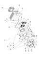
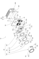
- FIG. 1 is a schematic perspective view of a vehicle lamp according to a first embodiment
- FIG. 2 is an exploded perspective view of the lamp unit of the first embodiment
- FIG. 2 is a horizontal sectional view of the optical unit of the first embodiment
- FIG. 9 is an exploded perspective view of a lamp unit according to a second embodiment
- FIG. 8 is a horizontal cross-sectional view of an optical unit according to a second embodiment
- FIG. 11 is an exploded perspective view of a lamp unit according to a third embodiment
- FIG. 11 is a horizontal cross-sectional view of an optical unit according to a third embodiment
- FIG. 1 is a schematic perspective view of a vehicle lamp according to this embodiment.
- the vehicle lamp 1 is a vehicle headlamp.
- the vehicle lamp 1 of this embodiment includes a lamp unit 10 and a housing 15 that accommodates the lamp unit 10 . Light emitted from the lamp unit 10 passes through the front surface of the housing 15 .
- FIG. 2 is an exploded perspective view of the lamp unit 10 of this embodiment.
- the lamp unit 10 includes a substrate 20 , a heat sink 30 , a fan 40 and an optical unit 50 .
- the substrate 20 is a plate member arranged along the vertical direction.
- a control connector 21 to which a control cable 21a is connected, a power connector 23 to which a power cable 23a is connected, an electronic component 25 such as a capacitor, and a light source section 27 are mounted on the substrate 20 .
- the control cable 21 a is connected to a control board (not shown), and the control board controls the electronic components 25 and the light source section 27 through the control cable 21 a and the board 20 .
- the power cable 23 a is connected to a power source (not shown), and the power source supplies power to the light source section 27 through the power cable 23 a and the substrate 20 .
- the power supply is also electrically connected to the control board.
- the control connector 21 and the power connector 23 are arranged side by side, the electronic component 25 is arranged above the power connector 23, and the light source unit 27 is above the control connector 21, the power connector 23, and the electronic component 25 and approximately in the center of the substrate 20. placed in
- the light source unit 27 includes a plurality of light emitting units.
- each light emitting unit for example, an LED (Light Emitting Diode) can be used.
- LED Light Emitting Diode
- Such light emitting units are arranged in a matrix in the vertical and horizontal directions, for example.
- the light emitting unit emits light forward when power is supplied. Whether or not light is emitted from each light-emitting portion and the amount of light emitted can be individually changed under the control of the control board. As long as the light emitting section can emit light, the configuration and arrangement are not particularly limited.
- the heat sink 30 includes a base plate 31, which is a plate member on which the substrate 20 is arranged, and a plurality of radiation fins 33 arranged in parallel on the side of the base plate 31 opposite to the substrate 20 side.
- a fan 40 is arranged at the rear ends of the plurality of radiation fins 33 .
- the fan 40 has an impeller (not shown), and blows air from behind the heat radiating fins 33 to between the heat radiating fins 33 by rotation of the impeller, thereby cooling the heat sink 30 .
- the optical unit 50 includes a lens unit 55 that adjusts the divergence angle of light incident from the light source section 27 and a holder 100 that supports the lens unit 55 .
- the lens unit 55 has shown the example which has three lenses 70,80,90.
- the lenses 70 , 80 , 90 are arranged to overlap each other in the thickness direction. placed in between. Also, the lens 70 is arranged in front of the light source section 27 .
- the lenses 70, 80, 90 are made of resin or glass, for example.
- the lenses 70, 80, and 90 each have a main body through which the light from the light source 27 is transmitted, and an outer peripheral portion provided on the outer periphery of the main body. Description will be made by assuming that the main body portions are main body portions 71, 81, and 91, and the outer peripheral portions are outer peripheral portions 73, 83, and 93, respectively.
- the external shape of the outer peripheral portions 73, 83, and 93 is generally an oval track shape elongated in the vertical direction, with the left and right portions of a circle cut off in a plane when viewed from the front.
- Engaged portions 120 are formed on the left and right portions of the outer peripheral portion 73 .
- Flat portions 83a and 93a are formed on the left and right portions of the outer peripheral portions 83 and 93, respectively.
- the planar portions 83 a and 93 a overlap each other and are located inside the engaged portion 120 .
- Protrusions 73 e are provided on the upper and lower sides of the front surface of the outer peripheral portion 73 . Each projection 73e is positioned symmetrically with respect to the main body portion 71. As shown in FIG.
- a slit 83 c and a hole are provided on the rear surface of the outer peripheral portion 83 .
- the slit 83c is positioned corresponding to one protrusion 73e and opens upward.
- the hole is positioned corresponding to the other projection 73e.
- the projections 73e are individually engaged with such slits 83c and holes.
- a pair of protrusions 83e are provided on the upper and lower sides of the front surface of the outer peripheral portion 83, similarly to the pair of protrusions 73e.
- a slit 93c and a hole 93d are provided on the rear surface of the outer peripheral portion 93 in the same manner as the slit 83c of the outer peripheral portion 83 and a hole (not shown).
- the slit 93c is positioned corresponding to one projection 83e, and the hole 93d penetrates the outer peripheral portion 93 in the front-rear direction and is positioned corresponding to the other projection 83e.
- the protrusions 83e are individually engaged with the slits 93c and the holes 93d.
- the lenses 70, 80, 90 are assembled as one unit by individually engaging the projections 73e with the slits 83c and the holes, and individually engaging the projections 83e with the slits 93c and the holes 93d. Also, the lenses 70, 80, 90 are circumferentially positioned relative to each other by the engagement described above.
- a protrusion 83g is provided on the front surface of the outer peripheral portion 83 of the lens 80, and a protrusion (not shown) is provided on the rear surface of the outer peripheral portion 83 as well.
- the projection 83 g contacts the rear surface of the outer peripheral portion 93 , and the projection (not shown) provided on the rear surface of the outer peripheral portion 83 contacts the front surface of the outer peripheral portion 73 .
- the holder 100 has light shielding properties and elasticity, and is made of resin, for example.
- the holder 100 has a cylindrical support portion 101 extending in the front-rear direction, a pair of left and right plate-like fixing portions 103 substantially perpendicular to the support portion 101, and a reinforcing plate 105, which are integrally formed. ing.
- the lenses 70, 80, and 90 of the lens unit 55 are aligned in the front-rear direction of the support portion 101 and fixed.
- the lens 90 is positioned on the front end side of the support portion 101 and the lens 70 is positioned on the rear end side of the support portion 101 .
- the support portion 101 has, for example, a cylindrical shape, but the shape is not particularly limited.
- the support portion 101 is provided with a projection 101b.
- the protrusion 101b is provided closer to the front end of the support portion 101 than the lens 90 of the lens unit 55 and protrudes toward the inside of the support portion 101 .
- a projection 101b is, for example, an inner flange provided on the front edge of the support portion 101, but is not limited to the inner flange and may be a member separate from the support portion 101 attached to the support portion 101.
- the protrusion 101b is arc-shaped in a front view, and two protrusions 101b are provided above and below. The projection 101b presses the front surface of the outer peripheral portion 93 of the lens 90 as will be described later.
- the inner peripheral surface of the support portion 101 is provided with a protrusion 101c.
- the protrusion 101 c extends in the front-rear direction and is provided at a position corresponding to the plane portion 83 a when the lens 80 is arranged inside the support portion 101 .
- the projection 101c abuts on the peripheral surface of the outer peripheral portion 73, and is positioned within the support portion 101 in the circumferential direction of the support portion 101.
- the rotation of the lenses 70, 80, 90 as a unit is restricted.
- a side wall of the support portion 101 is provided with a concave slit 101d.
- the slit 101d penetrates the support portion 101 in the radial direction of the support portion 101 .
- a pair of opposing sides of the concave slit 101 d extend in the front-rear direction, and the remaining one side extends in the circumferential direction of the support portion 101 and is provided on the rear end side of the support portion 101 .
- An engaging portion 110 is formed inside the slit 101d.
- the slit 101d and the locking portion 110 are provided on the left and right sides of the central axis of the support portion 101, respectively.
- the locking portion 110 and the slit 101d are provided at positions corresponding to the locked portion 120 and the planar portions 83a and 93a when the lenses 70, 80 and 90 are arranged inside the support portion 101. As shown in FIG.
- the locking portion 110 has an arm portion 111 .
- the arms 111 are separated from the side walls by the slits 101d on the rear end side of the support portion 101 and both sides of the support portion 101 in the circumferential direction. Further, the arm portion 111 is connected to the side wall on the front end side of the support portion 101 and is a part of the side wall. Such an arm portion 111 is elastically deformable in the radial direction of the support portion 101 .
- the right fixing portion 103 extends rightward from the right side of the rear end of the support portion 101, and the left fixing portion 103 extends leftward from the left side of the rear end.
- Each fixing part 103 is fixed to the substrate 20 as described later.
- the fixed portions 103 are provided behind the lenses 70 so that the lenses 70 located inside the support portions 101 are separated forward from the substrate 20 and the light source portion 27 when the respective fixed portions 103 are fixed to the substrate 20. .
- Each fixed portion 103 is provided with a cover portion 103a. Cover portion 103a is formed by a portion of each fixing portion 103 protruding forward.
- the respective cover portions 103a are positioned symmetrically with respect to the support portion 101, and the right cover portion 103a is provided at a position corresponding to the electronic component 25 with the respective fixing portions 103 fixed to the substrate 20, It covers the electronic component 25 .
- the reinforcing plates 105 are substantially triangular plate members, and are provided on the upper sides of the left and right fixed portions 103 and on the left and right cover portions 103a. Each reinforcing plate 105 is connected to the outer peripheral surface of the support portion 101 . In the circumferential direction of the support portion 101, the reinforcing plates 105 are provided on both sides of the slit 101d and overlap the slit 101d. Reinforcement plate 105 can suppress a decrease in strength of support portion 101 due to slit 101d. In addition, compared to the case where the reinforcing plate 105 does not overlap the slit 101d in the circumferential direction of the support portion 101, the decrease in the strength of the support portion 101 can be suppressed.
- the base plate 31 is provided with bosses 201 and screw holes 203 .
- a screw hole 205 is also provided in the fixed portion 103 .
- the boss 201 and screw holes 203 and 205 are provided at positions corresponding to the screw holes 207 provided in the substrate 20 .
- the boss 201 is inserted into screw holes 203 and 207 provided at positions corresponding to the boss 201 .
- screws (not shown) are engaged with threaded holes 203, 205, and 207 into which bosses 201 are not inserted.
- Another screw engages with the boss 201 and screw holes 203 and 207 into which the screw is not inserted.
- FIG. 3 is a horizontal cross-sectional view of the optical unit 50 of this embodiment in which the lenses 70, 80, and 90 are arranged inside the support portion 101.
- FIG. 3 is a horizontal cross-sectional view of the optical unit 50 of this embodiment in which the lenses 70, 80, and 90 are arranged inside the support portion 101.
- main body portions 71, 81, and 91 of lenses 70, 80, and 90 arranged along central axis 101a of support portion 101 in main body portion 71, incident surface 71a of light from light source portion 27 is convex rearward. , and the output surface 71b is convexly curved forward.
- the entrance surface 91a and the exit surface 91b are curved like the entrance surface 71a and the exit surface 71b.
- the main body portion 81 has an entrance surface 81a for light emitted from the light source portion 27 concavely curved forward, and an exit surface 81b concavely curved rearward.
- the projection 83g of the outer peripheral portion 83 contacts the rear surface of the outer peripheral portion 93, and the projection (not shown) provided on the rear surface of the outer peripheral portion 83 contacts the front surface of the outer peripheral portion 73.
- the locking portion 110 further has a claw portion 113 .
- the claw portion 113 is arranged on the inner peripheral surface and the rear end portion of the arm portion 111 .
- the claw portion 113 is located closer to the front end of the support portion 101 than the fixed portion 103 is.
- the claw portion 113 is provided at a position corresponding to the locked portion 120 provided on the outer peripheral portion 73 of the lens 70 in a state where the lenses 70, 80, and 90 are arranged inside the support portion 101, and extends toward the inside. protrude.
- the claw portion 113 has an inclined surface 113a inclined outward in the radial direction of the support portion 101 from front to rear.
- the claw portion 113 is positioned radially outward of the support portion 101 relative to the flat portions 83a and 93a. Therefore, when the lenses 80 and 90 pass through the claw portions 113, the claw portions 113 are prevented from coming into contact with the flat portions 83a and 93a, and abrasion of the claw portions 113 due to contact can be suppressed.
- an inclined surface 120a is provided at the front edge of the engaged portion 120 of the lens 70 . Like the inclined surface 113a, the inclined surface 120a is inclined outward in the radial direction of the support portion 101 from the front to the rear.
- the inclined surface 120a slides on the inclined surface 113a of the claw portion 113, and the arm portion 111 is pushed outward in the radial direction of the support portion 101 by the lens 70 and elastically deformed outward. open. Further, when the outer peripheral portion 73 passes through the claw portion 113, the arm portion 111 is closed inward due to elastic deformation. As a result, the claw portion 113 is snap-fitted to the rear edge portion of the locked portion 120 of the lens 70 and presses the locked portion 120 toward the front end side of the support portion 101 .
- the outer peripheral portion 73 of the lens 70 having the locked portion 120 presses the outer peripheral portion 83 toward the front end side through a projection (not shown) of the outer peripheral portion 83 that contacts the outer peripheral portion 73, and the outer peripheral portion 83 of the lens 80
- the outer peripheral portion 93 of the lens 90 is pressed to the front end side via the projection 83g.
- the outer peripheral portion 93 of the lens 90 is pressed against the protrusion 101b, and the lenses 70, 80, 90 of the lens unit 55 are held between the locking portion 110 and the protrusion 101b.
- the locking portion 110 presses the locked portion 120 toward the front end side of the supporting portion 101, and the locking portion 110 and the projection 101b lock the lens unit 55. Lenses 70, 80, 90 are sandwiched.
- the lens unit 55 since the lens unit 55 is directly held by the holder 100, movement of the lens unit 55 can be suppressed. Further, since the engaging portion 110 presses the engaged portion 120 engaged with the engaging portion 110 toward the front end side of the supporting portion 101, the lens unit 55 is sandwiched between the engaging portion 110 and the projection 101b. Movement of the lens unit 55 can be suppressed. Therefore, the lens unit 55 can be fixed more easily than when the lens unit is fixed to the holder using metal fittings or clips provided separately from the holder.
- the holder 100 further has a fixing portion 103 fixed to the substrate 20 which is a member outside the holder 100 .
- the holder 100 since the holder 100 is fixed to the external member, the holder 100 is more firmly attached to the external member than when the holder 100 is fixed to another member that is fixed to the external member. Fixed. Therefore, displacement of the lens unit 55 fixed inside the support portion 101 can be suppressed.
- the external member may be the base plate 31 .
- FIG. 4 is an exploded perspective view of the lamp unit 10 of this embodiment.
- illustration of the fan 40 is omitted.
- the configuration of the optical unit 50 is different from that of the optical unit 50 of the first embodiment.
- the external shapes of the outer peripheral portions 73, 83, 93 of the lenses 70, 80, 90 are generally oval track-shaped elongated in the vertical direction in the first embodiment, but are circular in the front view in the present embodiment. Further, each of the outer peripheral portions 73, 83, 93 has approximately the same diameter.
- Slits 73f are provided on the left and right sides of the outer peripheral portion 73 instead of the engaged portions 120. As shown in FIG. The slit 73f penetrates the outer peripheral portion 73 from the rear surface to the front surface and opens outward in the radial direction of the outer peripheral portion 73 . Slits 83f and 93f similar to the slit 73f are also provided on the left and right sides of the outer peripheral portions 83 and 93 instead of the flat portions 83a and 93a. When the lenses 70, 80, 90 are assembled, the slits 73f, 83f, 93f are provided on the same straight line.
- the optical unit 50 of this embodiment includes a first holder 130 and a second holder 150 instead of the holder 100 .
- the first holder 130 and the tubular second holder 150 have light shielding properties and elasticity, and are made of resin, for example.
- the structure of the first holder 130 is the same as the structure of the holder 100 of the first embodiment, except that the locked portion 120, which is an opening, is provided instead of the slit 101d and the locking portion 110, and the projection 101b is It is different in that it is ring-shaped.
- the engaged portion 120 is provided on the side wall of the support portion 101 and penetrates through the support portion 101 in the thickness direction.
- the locked portions 120 are provided on the left and right sides of the support portion 101 with the central axis 101a interposed therebetween, and are provided between the reinforcing plate 105 and the cover portion 103a in the circumferential direction of the support portion 101 .
- the locked portion 120 is positioned on the rear end side of the support portion 101 and is continuous with the fixed portion 103 .
- the support portion 101 of this embodiment has projections 101c as in the first embodiment.
- the projections 101c are slidably fitted into the slits 73f, 83f, and 93f. Thereby, the rotation of the lenses 70 , 80 , 90 in the circumferential direction of the support portion 101 within the support portion 101 is restricted.
- the fixing portion 103 of the first holder 130 is directly fixed to the substrate 20, which is a member outside the first holder, like the fixing portion 103 of the first embodiment.
- the second holder 150 has, for example, a cylindrical shape, but the shape is not particularly limited.
- the second holder 150 is arranged on the rear end side of the support portion 101 with respect to the lens 70 inside the support portion 101 .
- a lens 70 is arranged in the second holder 150 .
- an inner flange 151 is provided on the front edge of the second holder 150
- the outer peripheral portion 73 of the lens 70 is arranged on the inner flange 151 .
- a slit 151 a is provided in the inner flange 151 and extends from the inner flange 151 to the side wall of the second holder 150 .
- the slit 151a facilitates elastic deformation of the inner flange 151 .
- Two slits 151a are provided on each of the upper and lower sides. They are separated at approximately equal intervals in the circumferential direction of the second holder.
- the slit 153 extends longitudinally in the sidewall and further extends to the inner flange 151 .
- Two slits 153 are provided on the right side of the central axis of the second holder 150, and the other two slits 153 are provided on the left side of the central axis of the second holder 150.
- a locking portion 110 is provided between the two slits 153 on the left and right. Therefore, the locking portions 110 are provided on the left and right sides of the central axis of the second holder 150 .
- the arms 111 of the locking portion 110 are separated from the side walls by slits 153 on both sides of the rear end and the second holder 150 in the circumferential direction, and are connected to the inner flange 151 at the front end.
- the claw portion 113 is arranged on the outer peripheral surface of the arm portion 111 and at the rear end portion thereof.
- the claw portion 113 is provided at a position corresponding to the locked portion 120 of the first holder 130 when the lenses 70 , 80 , 90 and the second holder 150 are arranged inside the support portion 101 .
- the claw portion 113 protrudes outward in the radial direction of the second holder 150 .
- FIG. 5 is a horizontal sectional view of the optical unit 50 of this embodiment in which the lenses 70, 80, 90 and the second holder 150 are arranged inside the support portion 101.
- the projection 83g of the outer peripheral portion 83 contacts the rear surface of the outer peripheral portion 93
- the projection (not shown) provided on the rear surface of the outer peripheral portion 83 contacts the front surface of the outer peripheral portion 73. touch. Therefore, as shown in FIG. 5 , the front surface of the outer peripheral portion 83 is out of contact with the outer peripheral portion 93 , and the rear surface of the outer peripheral portion 83 is out of contact with the outer peripheral portion 73 . Note that the protrusions are not shown in FIG. 5 for ease of viewing.
- the second holder 150 is inserted into the support section 101 from the rear end of the support section 101 .
- the inclined surface 113a of the claw portion 113 slides along the edge 103c of the fixing portion 103 connected to the edge of the rear end side of the locked portion 120, which is an opening, so that the claw portion 113 and the arm slide.
- the portion 111 is pushed inward by the edge, and the arm portion 111 closes inward due to elastic deformation.
- the arm portion 111 is elastically deformed to open outward.
- the claw portion 113 is snap-fitted to the edge of the locked portion 120 .
- the second holder 150 is arranged behind the lens 70 , and the inner flange 151 abuts the rear surface of the outer peripheral portion 73 of the lens 70 .
- the rear surface of the outer peripheral portion 73 is also the rear surface of the lens unit 55 .
- the inner flange 151 presses the rear surface of the outer peripheral portion 73 of the lens 70 toward the front end side of the first holder 130 by elastic deformation of the inner flange 151 .
- the outer peripheral portion 73 of the lens 70 presses the outer peripheral portion 83 toward the front end side via a projection (not shown) of the outer peripheral portion 83 that contacts the outer peripheral portion 73, and the outer peripheral portion 83 of the lens 80 presses the lens through the projection 83g.
- the outer peripheral portion 93 of 90 is pressed to the front end side.
- the outer peripheral portion 93 of the lens 90 is pressed against the projection 101b, and the lenses 70, 80, 90 are sandwiched between the second holder 150 and the projection 101b.
- the locking portion 110 is locked to the locked portion 120 so that the second holder 150 can move the rear surface of the outer peripheral portion 73, which is the rear surface of the lens unit 55.
- the front end side of the first holder 130 is pressed, and the lens unit 55 is sandwiched between the second holder 150 and the projection 101b.
- the second holder 150 presses the rear surface of the outer peripheral portion 73, which is the rear surface of the lens unit 55, toward the front end side of the first holder 130 by engaging the locking portion 110 with the locked portion 120. Since the lens unit 55 is sandwiched between the second holder 150 and the protrusion 101b, movement of the lens unit 55 can be suppressed. Therefore, the lens unit 55 can be fixed more easily than when the lens unit is fixed to the holder using metal fittings or clips provided separately from the holder.
- the first holder 130 has a fixing portion 103 fixed to the substrate 20 which is a member outside the first holder 130 .
- the first holder 130 since the first holder 130 is fixed to the external member, the first holder 130 can be fixed to another member that is fixed to the external member. It is firmly fixed to an external member. Therefore, displacement of the lens unit 55 fixed inside the support portion 101 can be suppressed.
- the external member may be the base plate 31 .
- the locked portion 120 which is an opening is provided in the first holder 130 and the locking portion 110 is provided in the second holder 150 .
- the second holder 150 is arranged at the rear end of the lens 70 . Therefore, the locked portion 120 which is an opening is also provided at the rear end of the lens 70 . Therefore, when the supporting portion 101 is viewed from the side, the light from the lenses 70, 80, and 90 does not pass through the locked portion 120 as compared with the case where the locked portion 120 is provided so as to overlap the lenses 70, 80, and 90. Leakage can be suppressed.
- the locked portion 120 is not provided on the side wall of the support portion 101 that overlaps the lenses 70, 80, and 90, the design of the side wall can be improved.
- FIG. 6 is an exploded perspective view of the lamp unit 10 of this embodiment. In FIG. 6, illustration of the fan 40 is omitted.
- the lenses 80 and 90 have the same configuration as the lenses 80 and 90 of the second embodiment, but the configuration of the lens 70 is such that a slit 73c and a hole (not shown) are provided on the rear surface of the outer peripheral portion 73. is different from the configuration of the lens 70 of the second embodiment.
- the slit 73c and the hole (not shown) are positioned symmetrically with respect to the main body portion 71 .
- the slit 73c penetrates from the rear surface to the front surface of the outer peripheral portion 73 and opens upward.
- the lenses 70, 80, 90 and the second holder 150 of this embodiment are assembled as one unit using a jig (not shown). These may be assembled as a unit by inserting jigs into the slits 73f, 83f, and 93f.
- the respective configurations of the first holder 130 and the second holder 150 are different from those of the second embodiment.
- the first holder 130 of this embodiment has a support portion 101, and the support portion 101 has a protrusion 101b and a locked portion 120.
- the projection 101b has the same configuration as in the second embodiment.
- the locked portions 120 are provided on the left and right sides of the central axis of the support portion 101 .
- the locked portion 120 has an opening 121 and a recessed projection 123 provided at the edge of the opening 121 .
- the opening 121 is provided in the side wall of the support portion 101 and penetrates the support portion 101 in the thickness direction.
- the protrusion 123 protrudes from the outer peripheral surface of the support portion 101 and is arranged on a part of the edge of the opening 121 .
- a pair of opposing sides of the concave projection 123 extends in the front-rear direction, and the remaining one side extends in the circumferential direction of the support portion 101 and is provided on the rear end side of the opening.
- the second holder 150 of this embodiment includes a cylindrical mounting portion 159 extending in the front-rear direction, a pair of left and right plate-like fixing portions 103 substantially perpendicular to the mounting portion 159 , and a locking portion 110 . and each integrally formed.
- the placement portion 159 has, for example, a cylindrical shape, but the shape is not particularly limited.
- An outer peripheral portion 73 of the lens 70 is arranged on the front surface of the mounting portion 159 .
- Projections 155 e are provided on the upper and lower sides of the front surface of the mounting portion 159 .
- the projections 155e are positioned symmetrically, one projection 155e engages a slit 73c provided on the rear surface of the outer peripheral portion 73, and the other projection 155e engages a hole (not shown) provided on the rear surface of the outer peripheral portion 73. do.
- the right fixing portion 103 extends rightward from the right side of the rear end of the mounting portion 159, and the left fixing portion 103 extends leftward from the left side of the rear end.
- the left and right fixing portions 103 of the second holder 150 are directly fixed to the substrate 20 in the same manner as the fixing portions 103 of the first embodiment.
- the fixed portion 103 may be fixed to the base plate 31, which is an external member.
- the locking portions 110 are provided on the left and right portions of the side wall of the mounting portion 159 with the center axis of the mounting portion 159 interposed therebetween.
- the arm portion 111 of the locking portion 110 is L-shaped when viewed from above.
- L-shaped arm portion 111 includes one side connected to the rear end of mounting portion 159 and the other side on which claw portion 113 is arranged.
- One side extends radially outward of the mounting portion 159 .
- the other side extends toward the support portion 101 in the front-rear direction.
- a claw portion 113 is provided on the outer peripheral surface of the other side.
- the claw portion 113 protrudes radially outward from the mounting portion 159 .
- a notch 159a is provided in a portion of the side wall of the mounting portion 159 facing the other side so that the other side can bend inward due to elastic deformation.
- FIG. 7 is a horizontal sectional view of the optical unit 50 of this embodiment in which the lenses 70, 80, 90 and the mounting portion 159 are arranged inside the support portion 101.
- the projection 83g of the outer peripheral portion 83 contacts the rear surface of the outer peripheral portion 93
- the projection (not shown) provided on the rear surface of the outer peripheral portion 83 contacts the front surface of the outer peripheral portion 73. touch. Therefore, as shown in FIG. 7 , the front surface of the outer peripheral portion 83 is out of contact with the outer peripheral portion 93 , and the rear surface of the outer peripheral portion 83 is out of contact with the outer peripheral portion 73 . It should be noted that FIG. 7 does not show the protrusions for ease of viewing.
- the inclined surface 113a of the claw portion 113 slides on the inner peripheral surface of the support portion 101, and the claw portion 113 and the arm portion 111 are supported.
- the arm portion 111 closes inward due to elastic deformation. Since the notch 159a is provided in the side wall of the mounting portion 159, the locking portion 110 is further closed inward.
- the claw portion 113 is positioned at the opening 121 of the locked portion 120, the arm portion 111 is opened outward due to elastic deformation. As a result, the claw portion 113 is snap-fitted to the edge of the opening 121 of the locked portion 120 and the projection 123 .
- the front surface of the mounting portion 159 presses the rear surface of the outer peripheral portion 73 of the lens 70 toward the front end side of the first holder 130 .
- the outer peripheral portion 73 of the lens 70 presses the outer peripheral portion 83 of the lens 80 toward the front end side
- the outer peripheral portion 83 of the lens 80 presses the outer peripheral portion 93 of the lens 90 toward the front end side.
- the outer peripheral portion 93 of the lens 90 is pressed against the projection 101b, and the lenses 70, 80, 90 are sandwiched between the second holder 150 and the projection 101b.
- the second holder 150 engages the rear surface of the lens unit 55 with the front end of the first holder 130 by engaging the engaging portion 110 with the engaged portion 120 . Then, the second holder 150 and the projection 101b hold the lens unit 55 therebetween.
- the second holder 150 presses the rear surface of the outer peripheral portion 73, which is the rear surface of the lens unit 55, toward the front end side of the first holder 130 by engaging the locking portion 110 with the locked portion 120. Since the lens unit 55 is sandwiched between the second holder 150 and the protrusion 101b, movement of the lens unit 55 can be suppressed. Therefore, the lens unit 55 can be fixed more easily than when the lens unit is fixed to the holder using metal fittings or clips provided separately from the holder.
- the protrusions 155e are individually engaged with the slits 73c and holes (not shown). Thereby, the rotation of the lens 70 closest to the light source section 27 can be restricted with respect to the mounting section 159 .
- a headlamp has been described as an example of the vehicle lamp 1, but the lamp is not limited to a headlamp as long as it emits light that is emitted to the outside of the vehicle.
- the vehicle lamp 1 may emit light rearward or laterally of the vehicle.
- the lens unit 55 of the first, second, and third embodiments shows an example having three lenses 70, 80, and 90, it may have at least one lens.
- the locking portion 110 is provided on the second holder 150 and the locked portion 120 is provided on the supporting portion 101 .
- a vehicular lamp in which a lens unit can be easily fixed, and it can be used in fields such as automobiles.
Landscapes
- Engineering & Computer Science (AREA)
- General Engineering & Computer Science (AREA)
- Physics & Mathematics (AREA)
- Optics & Photonics (AREA)
- Microelectronics & Electronic Packaging (AREA)
- Mathematical Physics (AREA)
- General Physics & Mathematics (AREA)
- Non-Portable Lighting Devices Or Systems Thereof (AREA)
- Securing Globes, Refractors, Reflectors Or The Like (AREA)
Abstract
Description
図1は、本実施形態における車両用灯具の概略斜視図である。車両用灯具1は、自動車用の前照灯とされる。本実施形態の車両用灯具1は、灯具ユニット10と、灯具ユニット10を収容する筐体15とを備える。灯具ユニット10から出射する光は、筐体15の前面を透過する。
次に、本発明の第2実施形態について説明する。なお、上記において説明した構成と同様の構成については同一の符号を付し、特に説明する場合を除き、重複する説明は省略する。
次に、本発明の第3実施形態について説明する。なお、上記において説明した構成と同様の構成については同一の符号を付し、特に説明する場合を除き、重複する説明は省略する。
Claims (5)
- 少なくとも1つのレンズを有するレンズユニットと、
前記レンズユニットが内部に固定される筒状の支持部及び前記レンズユニットよりも前記支持部の前端側に設けられ前記支持部の内側に向かって突出する突起を有するホルダと、
前記支持部に設けられ、前記支持部の径方向に弾性変形可能な係止部と、
前記レンズユニットに設けられ、前記係止部に係止される被係止部と、
を備え、
前記係止部は前記被係止部を前記支持部の前記前端側に押圧し、前記係止部と前記突起とにより前記レンズユニットが挟持される
をことを特徴とする車両用灯具。 - 前記ホルダは、前記ホルダの外部の部材に固定される固定部をさらに有する
ことを特徴とする請求項1に記載の車両用灯具。 - 少なくとも1つのレンズを有するレンズユニットと、
前記レンズユニットが内部に固定される筒状の支持部及び前記レンズユニットよりも前記支持部の前端側に設けられ前記支持部の内側に向かって突出する突起を有する第1ホルダと、
前記支持部の内部における前記レンズユニットよりも前記支持部の後端側に配置される第2ホルダと、
前記支持部及び前記第2ホルダの一方に設けられ、前記支持部の径方向に弾性変形可能な係止部と、
前記支持部及び前記第2ホルダの他方に設けられ、前記係止部に係止される被係止部と、
を備え、
前記係止部が前記被係止部に係止することにより前記第2ホルダは前記レンズユニットの後面を前記第1ホルダの前記前端側に押圧し、前記第2ホルダと前記突起とにより前記レンズユニットが挟持される
をことを特徴とする備える車両用灯具。 - 前記第1ホルダは、前記第1ホルダの外部の部材に固定される固定部をさらに有する
ことを特徴とする請求項3に記載の車両用灯具。 - 前記第2ホルダは、前記第1ホルダの外部の部材に固定される固定部をさらに有する
ことを特徴とする請求項3に記載の車両用灯具。
Priority Applications (3)
| Application Number | Priority Date | Filing Date | Title |
|---|---|---|---|
| CN202280079938.XA CN118355228A (zh) | 2021-12-03 | 2022-12-01 | 车辆用灯具 |
| US18/714,629 US12560295B2 (en) | 2021-12-03 | 2022-12-01 | Vehicle lamp |
| JP2023565091A JPWO2023100987A1 (ja) | 2021-12-03 | 2022-12-01 |
Applications Claiming Priority (2)
| Application Number | Priority Date | Filing Date | Title |
|---|---|---|---|
| JP2021197337 | 2021-12-03 | ||
| JP2021-197337 | 2021-12-03 |
Publications (1)
| Publication Number | Publication Date |
|---|---|
| WO2023100987A1 true WO2023100987A1 (ja) | 2023-06-08 |
Family
ID=86612272
Family Applications (1)
| Application Number | Title | Priority Date | Filing Date |
|---|---|---|---|
| PCT/JP2022/044444 Ceased WO2023100987A1 (ja) | 2021-12-03 | 2022-12-01 | 車両用灯具 |
Country Status (4)
| Country | Link |
|---|---|
| US (1) | US12560295B2 (ja) |
| JP (1) | JPWO2023100987A1 (ja) |
| CN (1) | CN118355228A (ja) |
| WO (1) | WO2023100987A1 (ja) |
Citations (2)
| Publication number | Priority date | Publication date | Assignee | Title |
|---|---|---|---|---|
| KR20070041821A (ko) * | 2005-10-17 | 2007-04-20 | 기아자동차주식회사 | 차량의 헤드램프 조립체 |
| WO2020250758A1 (ja) * | 2019-06-10 | 2020-12-17 | 株式会社小糸製作所 | 光学ユニットおよび車両用灯具 |
Family Cites Families (2)
| Publication number | Priority date | Publication date | Assignee | Title |
|---|---|---|---|---|
| FR3026462B1 (fr) * | 2014-09-30 | 2019-06-28 | Valeo Vision Belgique | Dispositif lumineux de vehicule avec un element optique plaque avec le support de source lumineuse |
| JP7354003B2 (ja) | 2020-02-07 | 2023-10-02 | 株式会社小糸製作所 | 灯具ユニット |
-
2022
- 2022-12-01 US US18/714,629 patent/US12560295B2/en active Active
- 2022-12-01 CN CN202280079938.XA patent/CN118355228A/zh active Pending
- 2022-12-01 JP JP2023565091A patent/JPWO2023100987A1/ja active Pending
- 2022-12-01 WO PCT/JP2022/044444 patent/WO2023100987A1/ja not_active Ceased
Patent Citations (2)
| Publication number | Priority date | Publication date | Assignee | Title |
|---|---|---|---|---|
| KR20070041821A (ko) * | 2005-10-17 | 2007-04-20 | 기아자동차주식회사 | 차량의 헤드램프 조립체 |
| WO2020250758A1 (ja) * | 2019-06-10 | 2020-12-17 | 株式会社小糸製作所 | 光学ユニットおよび車両用灯具 |
Also Published As
| Publication number | Publication date |
|---|---|
| JPWO2023100987A1 (ja) | 2023-06-08 |
| US20250305650A1 (en) | 2025-10-02 |
| CN118355228A (zh) | 2024-07-16 |
| US12560295B2 (en) | 2026-02-24 |
Similar Documents
| Publication | Publication Date | Title |
|---|---|---|
| JP4500273B2 (ja) | 車両用前照灯 | |
| CN108343928B (zh) | 具备光源插座以及光导的灯具 | |
| JP7438209B2 (ja) | 光学ユニットおよび車両用灯具 | |
| US11543095B2 (en) | Vehicle lamp with particular attachment of spatial light modulator to heat sink | |
| JP4702326B2 (ja) | 照明装置用の発光ダイオード固定構造 | |
| CN115066581B (zh) | 灯具单元 | |
| CN211821815U (zh) | 灯具单元 | |
| US20130141930A1 (en) | Vehicular headlamp | |
| JP3280885B2 (ja) | 車両用灯具 | |
| CN110121616A (zh) | 透镜保持构造以及车辆用灯具 | |
| CN109073182B (zh) | 发光单元和车辆用灯具 | |
| JP2009016301A (ja) | 車両用灯具 | |
| CN209744278U (zh) | 车辆用前照灯 | |
| WO2023100987A1 (ja) | 車両用灯具 | |
| JP7407668B2 (ja) | 灯具ユニット | |
| CN214580873U (zh) | 光学装置和车辆 | |
| JP7354003B2 (ja) | 灯具ユニット | |
| CN116583693A (zh) | 透镜单元及车辆用灯具 | |
| WO2018123850A1 (ja) | 車両用灯具 | |
| CN110274209B (zh) | 车辆用前照灯 | |
| JP7302287B2 (ja) | 車両用灯具 | |
| JP7280104B2 (ja) | 灯具ユニット | |
| JP7217930B2 (ja) | 車両用灯具 | |
| CN214840284U (zh) | 照明装置 | |
| WO2025121274A1 (ja) | 車両用灯具 |
Legal Events
| Date | Code | Title | Description |
|---|---|---|---|
| 121 | Ep: the epo has been informed by wipo that ep was designated in this application |
Ref document number: 22901417 Country of ref document: EP Kind code of ref document: A1 |
|
| ENP | Entry into the national phase |
Ref document number: 2023565091 Country of ref document: JP Kind code of ref document: A |
|
| WWE | Wipo information: entry into national phase |
Ref document number: 202280079938.X Country of ref document: CN |
|
| NENP | Non-entry into the national phase |
Ref country code: DE |
|
| 122 | Ep: pct application non-entry in european phase |
Ref document number: 22901417 Country of ref document: EP Kind code of ref document: A1 |
|
| WWP | Wipo information: published in national office |
Ref document number: 18714629 Country of ref document: US |