WO2023100792A1 - 配線部材 - Google Patents
配線部材 Download PDFInfo
- Publication number
- WO2023100792A1 WO2023100792A1 PCT/JP2022/043725 JP2022043725W WO2023100792A1 WO 2023100792 A1 WO2023100792 A1 WO 2023100792A1 JP 2022043725 W JP2022043725 W JP 2022043725W WO 2023100792 A1 WO2023100792 A1 WO 2023100792A1
- Authority
- WO
- WIPO (PCT)
- Prior art keywords
- linear transmission
- transmission member
- fused
- wire
- cycle section
- Prior art date
- Legal status (The legal status is an assumption and is not a legal conclusion. Google has not performed a legal analysis and makes no representation as to the accuracy of the status listed.)
- Ceased
Links
Images



Classifications
-
- H—ELECTRICITY
- H01—ELECTRIC ELEMENTS
- H01B—CABLES; CONDUCTORS; INSULATORS; SELECTION OF MATERIALS FOR THEIR CONDUCTIVE, INSULATING OR DIELECTRIC PROPERTIES
- H01B7/00—Insulated conductors or cables characterised by their form
-
- H—ELECTRICITY
- H01—ELECTRIC ELEMENTS
- H01B—CABLES; CONDUCTORS; INSULATORS; SELECTION OF MATERIALS FOR THEIR CONDUCTIVE, INSULATING OR DIELECTRIC PROPERTIES
- H01B13/00—Apparatus or processes specially adapted for manufacturing conductors or cables
- H01B13/02—Stranding-up
-
- H—ELECTRICITY
- H01—ELECTRIC ELEMENTS
- H01B—CABLES; CONDUCTORS; INSULATORS; SELECTION OF MATERIALS FOR THEIR CONDUCTIVE, INSULATING OR DIELECTRIC PROPERTIES
- H01B7/00—Insulated conductors or cables characterised by their form
- H01B7/08—Flat or ribbon cables
- H01B7/0846—Parallel wires, fixed upon a support layer
-
- H—ELECTRICITY
- H01—ELECTRIC ELEMENTS
- H01B—CABLES; CONDUCTORS; INSULATORS; SELECTION OF MATERIALS FOR THEIR CONDUCTIVE, INSULATING OR DIELECTRIC PROPERTIES
- H01B7/00—Insulated conductors or cables characterised by their form
- H01B7/40—Insulated conductors or cables characterised by their form with arrangements for facilitating mounting or securing
-
- H—ELECTRICITY
- H02—GENERATION; CONVERSION OR DISTRIBUTION OF ELECTRIC POWER
- H02G—INSTALLATION OF ELECTRIC CABLES OR LINES, OR OF COMBINED OPTICAL AND ELECTRIC CABLES OR LINES
- H02G3/00—Installations of electric cables or lines or protective tubing therefor in or on buildings, equivalent structures or vehicles
- H02G3/30—Installations of cables or lines on walls, floors or ceilings
Definitions
- the present disclosure relates to wiring members.
- Patent Literature 1 discloses a wiring member in which an assembly line in which a plurality of linear transmission members are gathered is fixed to a base member.
- the twisted wire be fused and fixed to the base member more firmly.
- an object is to provide a technique that can more firmly fuse and fix the twisted wire to the base member.
- a wiring member includes a twisted wire obtained by twisting a first linear transmission member and a second linear transmission member, and a base member to which the twisted wire is fusion-bonded.
- the portion where the first linear transmission member and the second linear transmission member are arranged horizontally on the base member is defined as the horizontally aligned portion
- the portion where the linear transmission member is arranged vertically is defined as the vertically aligned portion
- the horizontally aligned portion and the vertically aligned portions alternately extend along the extending direction of the twisted wire, and a space between two continuous vertically aligned portions is a half-period section of the twist in the twisted wire
- the first linear transmission member and the second linear transmission member are fused to the base member to form a horizontal fused portion, and a first half-cycle section including the horizontal fused portion. is longer than the length of the second half-cycle section adjacent to the first half-cycle section.
- the twisted wire can be fused and fixed to the base member more firmly.
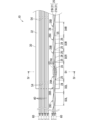
- FIG. 1 is a plan view showing a wiring member according to Embodiment 1.
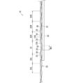
- FIG. FIG. 2 is a partially enlarged view of FIG. 3 is a side view showing the wiring member according to the first embodiment.
- FIG. FIG. 4 is a cross-sectional view taken along line IV-IV of FIG.
- FIG. 5 is an explanatory diagram showing a preparatory process for fusing twisted wires.
- FIG. 6 is an explanatory view showing a fusion process of twisted wires.
- the wiring member of the present disclosure is as follows.
- the portion where the linear transmission member and the second linear transmission member are arranged horizontally on the base member is defined as the horizontally aligned portion
- the portion where the linear transmission member is arranged vertically is defined as the vertically aligned portion
- the horizontally aligned portion and the vertically aligned portion are defined.
- first linear transmission member and the second linear transmission member are respectively fused to the base member to form laterally aligned fused portions, and the length of a first half cycle section including the laterally aligned fused portions is , a wiring member longer than the length of the second half-cycle section adjacent to the first half-cycle section.
- the length of the first half-cycle section including the side-by-side fused portion is longer than the length of the second half-cycle section adjacent to the first half-cycle section, thereby facilitating the lengthening of the side-by-side fused portion. Thereby, the twisted wire can be fused and fixed to the base member more firmly.
- the first linear transmission member and the second linear transmission member may be separated from each other in the parallel direction at the side-by-side fused portion.
- the first linear transmission member and the second linear transmission member are suppressed from overlapping each other during fusion bonding, and the first linear transmission member and the second linear transmission member are fused more firmly to the base member. can be fixed.
- the first linear transmission member and the second linear transmission member extend linearly parallel to each other in the side-by-side fused portion. good too.
- each of the first linear transmission member and the second linear transmission member can be strongly fused to the base member at the side-by-side fused portion, and the twisted wire can be more firmly fused and fixed to the base member. can be done.
- the first linear transmission member and the second linear transmission member are arranged on the base member in the second half cycle section. It may not be fused to the base member while being attached. This simplifies the fusion-bonding process by fusion-bonding a portion of the plurality of laterally-arranged portions of the twisted wire to the base member. Even in this case, the twisted wire can be more strongly fused and fixed to the base member by lengthening the laterally fused portion.
- the length dimension of the fused portion of the first linear transmission member in the side-by-side fused portion is the length of the first linear transmission member. It is longer than the width dimension, and the length dimension of the fused portion of the second linear transmission member in the side-by-side fused portion may be longer than the width dimension of the second linear transmission member.
- FIG. 1 is a plan view showing a wiring member 10 according to Embodiment 1.
- FIG. FIG. 2 is a partially enlarged view of FIG.
- FIG. 3 is a side view showing the wiring member 10 according to the first embodiment.
- FIG. 3 shows the wiring member 10 in the same range as in FIG.
- FIG. 4 is a cross-sectional view taken along line IV-IV of FIG.
- the wiring member 10 includes twisted wires 20 and a base member 30 .
- the wiring member 10 further includes an additional linear transmission member 40 .
- the twisted wire 20 and the additional linear transmission member 40 are fused and fixed to the base member 30 .
- the twisted wire 20 includes a first linear transmission member 21A and a second linear transmission member 21B.
- the first linear transmission member 21A and the second linear transmission member 21B are twisted.
- the first linear transmission member 21A and the second linear transmission member 21B are the same type of linear transmission member.
- the first linear transmission member 21A and the second linear transmission member 21B may be collectively referred to as the linear transmission member 21. be.
- the linear transmission member 21 may be any linear member that transmits electricity, light, or the like.
- the linear transmission member 21 may be a general electric wire having a core wire and a coating around the core wire, or may be a shielded wire, an enameled wire, a nichrome wire, an optical fiber, or the like.
- Various signal lines and various power lines may be used as linear transmission members for transmitting electricity.
- Linear transmission members that transmit electricity may be used as antennas, coils, etc. that transmit signals or power to or receive signals from space.
- the linear transmission member 21 has a transmission line body 22 and a covering layer 23 covering the transmission line body.
- the linear transmission member 21 is a general electric wire 21 (hereinafter simply referred to as the electric wire 21).
- the electric wire 21 has a core wire 22 as a transmission line body 22 and an insulating coating 23 as a coating layer 23 covering the core wire 22 .
- Each description regarding the electric wire 21 is applicable to the linear transmission member 21 except for inapplicable configurations.
- the core wire 22 is composed of one or more strands.
- the strands are made of conductors such as copper, copper alloys, aluminum, and aluminum alloys.
- the core wire 22 is composed of a plurality of strands, the strands may be twisted.
- the insulating coating 23 is formed by extrusion molding a resin material such as PVC (polyvinyl chloride) or PE (polyethylene) around the core wire 22 .
- the wire 21 is a so-called round wire having a circular cross section.
- At least part of the twisted wire 20 is arranged on the base member 30 .
- a portion of the twisted wire 20 including the intermediate portion is arranged on the base member 30 .
- the ends of the twisted wires 20 extend from the ends of the base member 30 to the outside of the base member 30 .
- the base member 30 is a member to which the twist wire 20 is fused and fixed on the main surface 32 .
- the base member 30 is a member having a main surface 32 that holds the twist line 20 along a predetermined path.
- the base member 30 may be any member as long as it has the main surface 32 for fusion-fixing the twisted wire 20 as described above, and may be formed in a sheet shape or in a three-dimensional shape. good too.
- the base member 30 may be described as a member having a flat portion, more specifically, as a bendable sheet member 30 .
- Each description relating to seat member 30 is applicable to base member 30, except where not applicable.
- the sheet member 30 is preferably made of a material containing a resin such as PVC (polyvinyl chloride), PET (polyethylene terephthalate), or PP (polypropylene). be.
- the sheet member 30 may be a sheet material whose interior is uniformly filled, or may be a non-woven sheet or the like. Sheet member 30 may also comprise a material such as metal.
- the sheet member 30 preferably has flexibility to be easily bent in the thickness direction.
- the sheet member 30 may be a single layer, or may be laminated in multiple layers. When a plurality of layers are laminated, it is conceivable that resin layers and resin layers are laminated, for example. Further, for example, it is conceivable that a resin layer and a metal layer are laminated.
- an additional linear transmission member 40 is fixed on the main surface 32 separately from the twisted wire 20 described above.
- the additional linear transmission member 40 may be a linear member that transmits electricity or light, like the linear transmission member 21 , or may be a member similar to the twisted wire 20 .
- the additional linear transmission member 40 will be described as a general electric wire 40 (hereinafter simply referred to as the electric wire 40) having a core wire 41 and an insulating coating 42. As shown in FIG. Each description regarding the wire 40 is applicable to the additional linear transmission member 40, except for inapplicable configurations.
- a plurality of additional linear transmission members 40 may be fixed on the main surface 32, or may be omitted.
- the electric wire 40 is also fused and fixed onto the main surface 32 .
- the portion where the wire 40 is fused and fixed onto the main surface 32 is the fused portion 54 .
- the wire 40 is fixed to the main surface 32 in parallel with the twisted wire 20 .
- the electric wire 40 and the twisted wire 20 may be branched and fixed along separate paths.
- the entire wire 40 and the entire twisted wire 20 may be fixed along separate paths on the major surface 32 .
- the base member 30 has at least one twisted wire 20 and at least one electric wire 40 (additional linear transmission line) on the main surface 32.
- the member 40) can be considered to be the member that keeps the member 40) flat.
- the base member 30 has a flat portion, and at least one twisted wire 20 and at least one electric wire 40 (additional linear transmission member 40) are fixed on the main surface 32 of the flat portion.
- the wiring member 10 can be considered to be a wiring member 10 having a flat portion that keeps the twisted wire 20 and the electric wire 40 (additional linear transmission member 40) flat.
- the base member 30 is a bendable sheet member 30 .
- the wiring member 10 is a flat wiring member 10 that keeps the twisted wire 20 and the electric wire 40 (additional linear transmission member 40) flat, and deforms according to the surface shape to be arranged. It can be considered as a possible wiring member 10 .
- the twisted wire 20 extends along the extension direction while changing the positional relationship between the first wire 21A and the second wire 21B.
- the side-by-side portion 24 extends along the extending direction of the twist line 20. and tandem portions 25 appear alternately.
- the side-by-side portion 24 is a portion where the first electric wires 21A and the second electric wires 21B are arranged in parallel on the sheet member 30 .
- the vertically aligned portion 25 is a portion where the first electric wires 21A and the second electric wires 21B are vertically arranged so as to be stacked on the main surface 32 of the sheet member 30 .
- a shift portion 26 for changing the positional relationship of the electric wires 21 can be regarded between the horizontally arranged portion 24 and the vertically arranged portion 25 .
- the positions of the first electric wires 21A and the positions of the second electric wires 21B are switched left and right in the two continuous horizontal portions 24 .
- the position of the first electric wire 21A and the position of the second electric wire 21B are reversed vertically.
- the position of the first electric wire 21A and the position of the second electric wire 21B in a certain vertically aligned portion 25 and the vertically aligned portion 25 passing through the vertically aligned portion 25, the vertically aligned portion 24, the vertically aligned portion 25, and the horizontally aligned portion 24. are the same, and this interval is one twist period in the twisted wire 20 .
- the interval between three consecutive tandem portions 25 is one twist period section
- the interval between two consecutive tandem portions 25 is a half-period twist section.
- first electric wires 21A and the second electric wires 21B are arranged horizontally on the principal surface 32 of the laterally-arranged portion 24, each of the first electric wires 21A and the second electric wires 21B comes into contact with the principal surface 32 of the sheet member 30. is in a possible position.
- the laterally-arranged first electric wires 21A and the laterally-arranged second electric wires 21B are respectively fused and fixed to the sheet member 30, thereby forming a transversely-arranged fused portion 50.
- the first electric wires 21A and the second electric wires 21B are arranged horizontally in the horizontal portion 24, they can stably contact the main surface 32 of the sheet member 30.
- FIG. Therefore, the first electric wires 21A and the second electric wires 21B are easily fused and fixed onto the main surface 32 of the sheet member 30 in a stable manner.
- the portion where the first electric wires 21A and the sheet member 30 are fused is called a first fused portion 51
- the portion where the second electric wires 21B and the sheet member 30 are fused is called a second fused portion. It is sometimes called a fused portion 52 .
- the side-by-side fused portion 50 can also be regarded as having a first fused portion 51 and a second fused portion 52 .
- the first fused portion 51 and the second fused portion 52 are generally of the same length.
- the first fused portion 51 and the second fused portion 52 may have slightly different lengths.
- a plurality of laterally-arranged portions 24 are arranged linearly at intervals. Only one of the plurality of horizontal portions 24 may be formed with the horizontal fused portion 50 , or a plurality of the plurality of horizontal portions 24 may be provided with the horizontal fused portions 50 . In the latter case, the laterally-aligned fused portions 50 may be continuously provided for the plurality of laterally-aligned portions 24 without passing through a portion where the laterally-aligned fused portions 50 are not provided, or the laterally-aligned portions 24 may be horizontally aligned for each of the plurality of laterally-aligned portions 24 . A fused portion 50 may be provided. Here, as shown in FIG. 1, laterally aligned fused portions 50 are provided at a plurality of laterally aligned portions 24 that are not continuous among the plurality of laterally aligned portions 24 .
- a half-cycle section including the side-by-side fused portion 50 is defined as a first half-cycle section 28A.
- a half-cycle section next to the first half-cycle section 28A is defined as a second half-cycle section 28B, and hereinafter, as the distance from the first half-cycle section 28A increases, a third half-cycle section 28C and a fourth half-cycle section 28D are defined. .
- the second half-cycle section 28B, the third half-cycle section 28C, and the fourth half-cycle section 28D are generally present on both sides of the first half-cycle section 28A, respectively.
- first half-period section 28A is at the end of the sheet member 30 and the end of the twist line 20 is provided near the end of the sheet member 30, the end of the twist line 20 , the second half-cycle section 28B, the third half-cycle section 28C, and the fourth half-cycle section 28D may not be provided.
- first linear transmission member 21A and the second linear transmission member 21B are arranged on the base member 30 in each of the two second half-cycle sections 28B on one side and the other side of the first half-cycle section 28A. However, it is not fused to the base member 30 .
- the first linear transmission member 21A and the second linear transmission member 21B are arranged on the base member 30 also in the third half-cycle section 28C and the fourth half-cycle section 28D on one side of the first half-cycle section 28A. However, it is not fused to the base member 30 .
- the dimension D1 is the length of the first half-period section 28A.
- the dimensions D2L and D2R are the lengths of the second half-period section 28B.
- the dimensions D3L, D3R are the lengths of the third half cycle section 28C.
- Dimension D4R is the length of fourth half-period section 28D.
- the sign L and the sign R of the length of the second half-cycle section 28B indicate which second half-cycle section 28B on one side or the other side of the first half-cycle section 28A. The same applies to the third half-cycle section 28C and the fourth half-cycle section 28D.
- the length D1 of the first half-cycle section 28A is longer than the lengths D2R and D2L of the second half-cycle section 28B.
- the length D1 of the first half-cycle section 28A is longer than the respective lengths D2R and D2L of the two second half-cycle sections 28B on one side and the other side of the first half-cycle section 28A.
- the length D1 of the first half-cycle section 28A should be longer than at least one of the lengths D2R and D2L of the two second half-cycle sections 28B on one side and the other side of the first half-cycle section 28A. .
- the length D1 of the first half-cycle section 28A is longer than the lengths D3R and D3L of the third half-cycle section 28C.
- the length D1 of the first half-cycle section 28A is longer than the respective lengths D3R and D3L of the two third half-cycle sections 28C on one side and the other side of the first half-cycle section 28A.
- the length D1 of the first half-cycle section 28A should be longer than at least one of the lengths D3R and D3L of the two third half-cycle sections 28C on one side and the other side of the first half-cycle section 28A. .
- the length D1 of the first half-cycle section 28A is longer than the length of the fourth half-cycle section 28D.
- the length D1 of the first half-cycle section 28A is longer than the length D4R of the fourth half-cycle section 28D on one side of the first half-cycle section 28A.
- the length of the first half-cycle section 28A may be longer than the length of the fourth half-cycle section 28D on the other side of the first half-cycle section 28A.
- the lengths D2R and D2L of the second half-cycle section 28B are shorter than the lengths D3R and D3L of the third half-cycle section 28C. This is because the lengths D2R and D2L of the second half-cycle sections 28B are shortened by increasing the length D1 of the first half-cycle section 28A.
- the lengths D2R and D2L of the second half-cycle section 28B may be the same as the lengths D3R and D3L of the third half-cycle section 28C. For example, by untwisting the twisted wire 20, it is possible to prevent the lengths D2R and D2L of the second half-cycle section 28B from being shortened even if the length D1 of the first half-cycle section 28A is lengthened.
- the length D1 of the first half-cycle section 28A may be longer than the average length of all half-cycle sections in the twist line 20.
- the average length of all half-period sections in the twisted wire 20 is close to half the twist pitch (length of one period section) set when the twisted wire 20 is manufactured (hereinafter referred to as half-pitch).
- the twist pitch is not particularly limited, but may be, for example, 25 mm to 40 mm.
- the length D1 of the first half-cycle section 28A may be three times or less, two times or less, or 1.5 times or less the lengths D2R and D2L of the second half-cycle sections 28B. may Also, the length D1 of the first half-period section 28A may be three times or less the half pitch, may be two times or less, or may be 1.5 times or less. For example, the length D1 of the first half period section 28A may be 1.2 times the half pitch.
- the first linear transmission member 21A and the second linear transmission member 21B extend linearly parallel to each other.
- the side-by-side portion 24 in the first half-cycle section 28A is closer to a straight line than the side-by-side portion 24 in the second half-cycle section 28B.
- the length of contact of the first linear transmission member 21A with the base member 30 and the length of contact of the second linear transmission member 21B with the base member 30 are increased.
- the sign L and the sign R of the length of the second half-cycle section 28B indicate which second half-cycle section 28B on one side or the other side of the first half-cycle section 28A. The same applies to the third half-cycle section 28C and the fourth half-cycle section 28D.
- the dimension L1 is the interval between the first linear transmission member 21A and the second linear transmission member 21B.
- the dimension L2 is the width dimension (here, the diameter) of the electric wire 21 .
- Dimension L3 is the distance between twisted wire 20 and wire 40 .
- a dimension L4 is the interval between the electric wires 40 .
- dimension L1 may be less than or equal to dimension L2.
- Dimension L1 may be less than or equal to dimension L3.
- Dimension L1 may be less than or equal to dimension L4.
- the first electric wire 21A and the second electric wire 21B may or may not be in contact with each other.
- the dimension WD1 is the length dimension of the fusion-bonded portion of the electric wire 21 in the laterally-aligned fusion-bonded portion 50 .
- the length dimension WD1 of the fused portions 51 and 52 of the wire 21 in the side-by-side fused portion 50 is longer than the width dimension L2 of the wire 21 .
- the length dimension of the fusion-bonded portion of the first electric wire 21A in the side-by-side fusion-bonded portion 50 is the same as the length dimension of the fusion-bonded portion of the second electric wire 21B.
- the length dimension of the fused portions 51 , 52 of the wire 21 may be longer than the length dimension of the fused portion 54 of the wire 40 .
- various fusion means such as ultrasonic fusion, heat-pressure fusion, hot-air fusion, and high-frequency fusion can be employed.
- the electric wire 21 and the sheet member 30 are brought into the fusion-fixed state by the means.
- the fused and fixed state is formed by ultrasonic fusion
- the electric wire 21 and the sheet member 30 are brought into the fused and fixed state by ultrasonic fusion.
- the portion where the fused and fixed state is formed (the portion where the electric wire 21 and the sheet member 30 are fixed) is called the fused portion, the portion fixed by ultrasonic fusion is called the ultrasonic fused portion, and the portion fixed by heat and pressure fusion is called the fused portion.
- the portion may also be referred to as a heat and pressure fused portion or the like.
- both the resin contained in the coating of the electric wire 21 and the resin contained in the sheet member 30 may be melted in the fusion fixation. In this case, both resins may mix and a clear interface may not be formed. In particular, when the coating of the electric wire 21 and the sheet member 30 contain resins that are easily compatible, such as the same resin material, both resins may be mixed and a clear interface may not be formed.
- the structure for fixing the electric wire 40 the same structure as that for fixing the twisted wire 20 to the sheet member 30 can be applied, and for example, a structure for fixing by ultrasonic fusion can be adopted.
- a connection member 60 such as an electrical connector or an optical connector may be provided at the end of the twisted wire 20 and the end of the electric wire 40, as shown in FIG.
- the wiring member 10 becomes the wiring member 10 that connects the plurality of electrical components and the optical components.
- FIG. 5 is an explanatory diagram showing a preparatory process for fusing the twisted wire 20.
- FIG. 6A and 6B are explanatory diagrams showing the fusing process of the twisted wire 20.
- FIG. 5 is an explanatory diagram showing a preparatory process for fusing the twisted wire 20.
- FIG. 6A and 6B are explanatory diagrams showing the fusing process of the twisted wire 20.
- FIG. 5 is an explanatory diagram showing a preparatory process for fusing the twisted wire 20.
- FIG. 6A and 6B are explanatory diagrams showing the fusing process of the twisted wire 20.
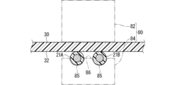
- Ultrasonic fusion machine 80 has horn 82 and anvil 84 . Twisted line 20 is retained by anvil 84 .
- the twist line 20 indicated by a solid line is the twist line 20 before fusion.
- the twisted wires 20 before fusion are continuous with a uniform pitch.
- a region indicated by a two-dot chain line circle indicates a portion 27 to be fused of the twist line 20 .
- the portion to be fused 27 is held by the anvil 84 .
- the twist line 20 indicated by a two-dot chain line is shown held by the anvil 84 .
- Two grooves 85 are formed in the anvil 84 . Two grooves 85 are separated by a partition 86 . The first electric wire 21A and the second electric wire 21B are held separately in two grooves 85, respectively. At this time, the length dimension of the groove 85 is longer than the length dimension of the side-by-side portion 24 in the portion 27 to be fused. Therefore, the twisted wire 20 is held by the anvil 84 with the longitudinal dimension of the side-by-side portion 24 of the portion to be fused 27 being elongated. At this time, a portion of the twisted wire 20 that will be the portion to be fused 27 may be untwisted. As a result, shortening of the half-period section adjacent to the portion to be fused 27 is suppressed.
- the sheet member 30 is arranged as shown in FIG.
- the sheet member 30 is arranged so as to cover the first electric wires 21A and the second electric wires 21B.
- a horn 82 is applied to the outside of the sheet member 30 , and ultrasonic vibration energy is applied to the contact portion between the sheet member 30 and the electric wire 21 via the horn 82 . Thereby, the contact portion between the sheet member 30 and the electric wire 21 is fused.
- the length of the first electric wire 21A and the second electric wire 21B held by the anvil 84 is reduced.
- the corresponding length can be fused with the sheet member 30 .
- the length of the first half-cycle section 28A including the side-by-side fused portion 50 can be made longer than the length of the second half-cycle section 28B.
- the first electric wire 21A and the second electric wire 21B are fused to the sheet while being spaced apart in the parallel direction.
- the first electric wires 21A and the second electric wires 21B are fused to the sheet in parallel and linearly.
- ultrasonic fusion may be performed on each of the plurality of side-by-side portions 24 to form the side-by-side fused portions 50 one by one.
- a horn 82 or anvil 84 having a plurality of pressurizing portions projecting at intervals of integral multiples of the pitch of the laterally-arranged portions 24 is used, and the plurality of laterally-arranged portions 24 are collectively subjected to ultrasonic welding, Multiple side-by-side fused portions 50 may be formed simultaneously.
- At least one of the horn 82 and anvil 84 is moved along the twist line 20 to pressurize and apply ultrasonic vibrational energy to the horn 82 and anvil 84 at the target lateral portion 24, and Multiple side-by-side fused portions 50 may be formed sequentially.
- the length D1 of the first half-cycle section 28A including the side-by-side fused portion 50 is the length D2R of the second half-cycle section 28B adjacent to the first half-cycle section 28A.
- D2L makes it easier to lengthen the side-by-side fused portions 50 .
- the twisted wire 20 can be fused and fixed to the base member 30 more firmly.
- the first linear transmission member 21A and the second linear transmission member 21B are separated in the parallel direction.
- the first linear transmission member 21A and the second linear transmission member 21B are prevented from overlapping each other during fusion bonding, and the first linear transmission member 21A and the second linear transmission member 21B are strengthened. It can be fused and fixed to the base member 30 .
- the first linear transmission member 21A and the second linear transmission member 21B linearly extend parallel to each other.
- the first linear transmission member 21A and the second linear transmission member 21B are more likely to be strongly fused to the base member 30 at the side-by-side fused portion 50, and the twisted wire 20 is more firmly attached to the base member 30. can be fused and fixed.
- the first linear transmission member 21A and the second linear transmission member 21B are arranged on the base member 30 and are not fused to the base member 30 .
- a part of the plurality of laterally-arranged portions 24 of the twisted wire 20 is fused to the base member 30, thereby simplifying the fusion bonding process.
- the twisted wire 20 can be fused and fixed to the base member 30 more firmly by lengthening the side-by-side fused portion 50 .
- the length dimension of the fused portion of the first linear transmission member 21A in the side-by-side fused portion 50 is longer than the width dimension of the first linear transmission member 21A.
- the length dimension of the fused portion of the second linear transmission member 21B in the side-by-side fused portion 50 is longer than the width dimension of the second linear transmission member 21B.
- first linear transmission member 21A and the second linear transmission member 21B have been described as separated in the parallel direction in the side-by-side fused portion 50, but this is not an essential configuration.
- first linear transmission member 21A and the second linear transmission member 21B may be in contact with each other in the parallel direction.
- first linear transmission member 21A and the second linear transmission member 21B in the side-by-side fused portion 50 have been described as extending linearly parallel to each other, but this is essential. is not the composition of
- the first linear transmission member 21A and the second linear transmission member 21B may extend in different directions.
- the first linear transmission member 21A and the second linear transmission member 21B have been described so far as being arranged on the base member 30 and not fused to the base member 30. However, this is not an essential configuration.
- the first linear transmission member 21A and the second linear transmission member 21B may be fused to the base member 30 also in the second half-period section 28B. Even in this case, by providing the first half-period section 28A having a long half-period section, it is possible to provide a portion having a long side-by-side fused portion 50 .
- the length dimension of the fused portion of the first linear transmission member 21A in the laterally aligned fused portion 50 was longer than the width dimension of the first linear transmission member 21A, and the second line in the laterally aligned fused portion 50
- the length dimension of the fused portion of the linear transmission member 21B has been described as being longer than the width dimension of the second linear transmission member 21B, this is not an essential configuration.
- the length dimension of the fused portion of the first linear transmission member 21A in the side-by-side fused portion 50 may be equal to or shorter than the width dimension of the first linear transmission member 21A.
- the length dimension of the fused portion of the second linear transmission member 21B in the side-by-side fused portion 50 may be equal to or shorter than the width dimension of the second linear transmission member 21B.
Landscapes
- Engineering & Computer Science (AREA)
- Manufacturing & Machinery (AREA)
- Architecture (AREA)
- Civil Engineering (AREA)
- Structural Engineering (AREA)
- Installation Of Indoor Wiring (AREA)
- Connections Effected By Soldering, Adhesion, Or Permanent Deformation (AREA)
- Communication Cables (AREA)
- Details Of Indoor Wiring (AREA)
Abstract
Description
最初に本開示の実施態様を列記して説明する。
本開示の配線部材の具体例を、以下に図面を参照しつつ説明する。なお、本開示はこれらの例示に限定されるものではなく、請求の範囲によって示され、請求の範囲と均等の意味及び範囲内でのすべての変更が含まれることが意図される。
以下、実施形態1にかかる配線部材について説明する。各図面では、説明の便宜上、構成の一部を誇張又は簡略化して示す場合がある。また、各部分の寸法比率については各図面で異なる場合がある。また、本明細書における「垂直」は、厳密に垂直な状態のみでなく、概ね垂直な状態も含まれる。概ね垂直とは、例えば2つの方向の成す角度が80度以上90度未満、好ましくは85度以上90度未満の状態である。また、本明細書における「平行」は、厳密に平行な状態のみでなく、概ね平行な状態も含まれる。概ね平行とは、例えば2つの方向の成す角度が10度以下、好ましくは5度以下の状態である。
図5はツイスト線20を融着するための準備工程を示す説明図である。図6はツイスト線20の融着工程を示す説明図である。
このように構成された配線部材10によると、横並び融着部分50を含む第1半周期区間28Aの長さD1が、第1半周期区間28Aの隣の第2半周期区間28Bの長さD2R、D2Lよりも長いことによって、横並び融着部分50を長くすることが容易となる。これにより、ツイスト線20をより強固にベース部材30に融着固定することができる。
これまで、横並び融着部分50において、第1線状伝送部材21Aと第2線状伝送部材21Bとが並列方向に離れているものとして説明されたが、このことは必須の構成ではない。横並び融着部分50において、第1線状伝送部材21Aと第2線状伝送部材21Bとが並列方向に接していてもよい。
20 ツイスト線
21 電線(線状伝送部材)
21A 第1電線(第1線状伝送部材)
21B 第2電線(第2線状伝送部材)
22 芯線(伝送線本体)
23 絶縁被覆(被覆層)
24 横並び部分
25 縦並び部分
26 シフト部分
27 融着予定部分
28A 第1半周期区間
28B 第2半周期区間
28C 第3半周期区間
28D 第4半周期区間
30 シート部材(ベース部材)
32 主面
40 電線(追加線状伝送部材)
41 芯線
42 絶縁被覆
50 横並び融着部分
51 第1融着部分
52 第2融着部分
54 融着部分
60 接続部材
80 超音波融着機
82 ホーン
84 アンビル
85 溝
86 仕切
Claims (5)
- 第1線状伝送部材と第2線状伝送部材とが撚られたツイスト線と、
前記ツイスト線が融着固定されたベース部材と、
を備え、
前記ツイスト線のうち前記第1線状伝送部材と前記第2線状伝送部材とが前記ベース部材上に横に並んだ部分が横並び部分とされ、縦に並んだ部分が縦並び部分とされたとき、
前記横並び部分と前記縦並び部分とが、前記ツイスト線の延在方向に沿って交互に延在しており、
連続する2つの前記縦並び部分の間が前記ツイスト線における撚りの半周期区間とされ、
前記横並び部分において、前記第1線状伝送部材と前記第2線状伝送部材とがそれぞれ前記ベース部材に融着されて横並び融着部分が形成され、
前記横並び融着部分を含む第1半周期区間の長さが、前記第1半周期区間の隣の第2半周期区間の長さよりも長い、配線部材。 - 請求項1に記載の配線部材であって、
前記横並び融着部分において、前記第1線状伝送部材と前記第2線状伝送部材とが並列方向に離れている、配線部材。 - 請求項1又は請求項2に記載の配線部材であって、
前記横並び融着部分において、前記第1線状伝送部材と前記第2線状伝送部材とが、互いに平行に、直線状に延びている、配線部材。 - 請求項1から請求項3のいずれか1項に記載の配線部材であって、
前記第2半周期区間において、前記第1線状伝送部材と前記第2線状伝送部材とが前記ベース部材上に配置されつつ前記ベース部材に融着されていない、配線部材。 - 請求項1から請求項4のいずれか1項に記載の配線部材であって、
前記横並び融着部分における前記第1線状伝送部材の融着部分の長さ寸法は、前記第1線状伝送部材の幅寸法よりも長く、
前記横並び融着部分における前記第2線状伝送部材の融着部分の長さ寸法は、前記第2線状伝送部材の幅寸法よりも長い、配線部材。
Priority Applications (2)
| Application Number | Priority Date | Filing Date | Title |
|---|---|---|---|
| US18/711,234 US20250006404A1 (en) | 2021-11-30 | 2022-11-28 | Wiring member |
| CN202280076255.9A CN118266141A (zh) | 2021-11-30 | 2022-11-28 | 配线构件 |
Applications Claiming Priority (2)
| Application Number | Priority Date | Filing Date | Title |
|---|---|---|---|
| JP2021194128A JP7753837B2 (ja) | 2021-11-30 | 2021-11-30 | 配線部材 |
| JP2021-194128 | 2021-11-30 |
Publications (1)
| Publication Number | Publication Date |
|---|---|
| WO2023100792A1 true WO2023100792A1 (ja) | 2023-06-08 |
Family
ID=86612223
Family Applications (1)
| Application Number | Title | Priority Date | Filing Date |
|---|---|---|---|
| PCT/JP2022/043725 Ceased WO2023100792A1 (ja) | 2021-11-30 | 2022-11-28 | 配線部材 |
Country Status (4)
| Country | Link |
|---|---|
| US (1) | US20250006404A1 (ja) |
| JP (1) | JP7753837B2 (ja) |
| CN (1) | CN118266141A (ja) |
| WO (1) | WO2023100792A1 (ja) |
Families Citing this family (1)
| Publication number | Priority date | Publication date | Assignee | Title |
|---|---|---|---|---|
| JP7683490B2 (ja) * | 2022-01-14 | 2025-05-27 | 株式会社オートネットワーク技術研究所 | 配線部材 |
Citations (1)
| Publication number | Priority date | Publication date | Assignee | Title |
|---|---|---|---|---|
| JPS61218007A (ja) * | 1985-03-22 | 1986-09-27 | 昭和電線電纜株式会社 | フレキシブルツイストフラツトケ−ブルおよびその製造装置 |
Family Cites Families (9)
| Publication number | Priority date | Publication date | Assignee | Title |
|---|---|---|---|---|
| US3736366A (en) * | 1972-04-27 | 1973-05-29 | Bell Telephone Labor Inc | Mass bonding of twisted pair cables |
| US4012577A (en) * | 1975-04-30 | 1977-03-15 | Spectra-Strip Corporation | Multiple twisted pair multi-conductor laminated cable |
| US4486619A (en) * | 1983-05-12 | 1984-12-04 | Minnesota Mining And Manufacturing Company | Uniform twisted wire pair electrical ribbon cable |
| US5276759A (en) * | 1992-01-09 | 1994-01-04 | Raychem Corporation | Flat cable |
| US5502287A (en) * | 1993-03-10 | 1996-03-26 | Raychem Corporation | Multi-component cable assembly |
| JP3596348B2 (ja) * | 1999-04-22 | 2004-12-02 | 日立電線株式会社 | フラットケーブル及びその製造方法 |
| JP2002313148A (ja) * | 2001-04-06 | 2002-10-25 | Hitachi Cable Ltd | フラットケーブル |
| JP2019218007A (ja) * | 2018-06-22 | 2019-12-26 | 株式会社エクォス・リサーチ | 車両 |
| JP7192628B2 (ja) | 2018-08-22 | 2022-12-20 | 株式会社オートネットワーク技術研究所 | 配線部材 |
-
2021
- 2021-11-30 JP JP2021194128A patent/JP7753837B2/ja active Active
-
2022
- 2022-11-28 US US18/711,234 patent/US20250006404A1/en active Pending
- 2022-11-28 CN CN202280076255.9A patent/CN118266141A/zh active Pending
- 2022-11-28 WO PCT/JP2022/043725 patent/WO2023100792A1/ja not_active Ceased
Patent Citations (1)
| Publication number | Priority date | Publication date | Assignee | Title |
|---|---|---|---|---|
| JPS61218007A (ja) * | 1985-03-22 | 1986-09-27 | 昭和電線電纜株式会社 | フレキシブルツイストフラツトケ−ブルおよびその製造装置 |
Also Published As
| Publication number | Publication date |
|---|---|
| JP2023080662A (ja) | 2023-06-09 |
| JP7753837B2 (ja) | 2025-10-15 |
| US20250006404A1 (en) | 2025-01-02 |
| CN118266141A (zh) | 2024-06-28 |
Similar Documents
| Publication | Publication Date | Title |
|---|---|---|
| JP6798471B2 (ja) | ワイヤーハーネスおよびワイヤーハーネスの製造方法 | |
| JP7597182B2 (ja) | 配線部材 | |
| US9643545B2 (en) | Wire harness | |
| WO2023100792A1 (ja) | 配線部材 | |
| US9251926B2 (en) | Collective conductor and method for producing collective conductor | |
| JP2005174689A (ja) | 編組電線及びその配索方法 | |
| CN112334997B (zh) | 线束 | |
| JP7192628B2 (ja) | 配線部材 | |
| US12136505B2 (en) | Wiring member | |
| WO2021192852A1 (ja) | 配線部材 | |
| JP2005183018A (ja) | ヒータ線 | |
| WO2020144855A1 (ja) | 配線部材 | |
| JP7459583B2 (ja) | 配線部材 | |
| JP2016167340A (ja) | ジョイント部材及びワイヤーハーネス | |
| WO2022202667A1 (ja) | 配線部材 | |
| JP2015015221A (ja) | ツイストペア電線および該ツイストペア電線の形成方法 | |
| CN116325367B (zh) | 配线构件 | |
| CN113168938A (zh) | 布线部件 | |
| JP2026047748A (ja) | 接続構造体及び接続構造体の製造方法 | |
| WO2020166171A1 (ja) | ワイヤハーネス | |
| JP2025139632A (ja) | ワイヤハーネス、及び、外装部材 | |
| JP2025025058A (ja) | 超音波接合装置およびワイヤハーネス | |
| JP2006261084A (ja) | ヒータ線 |
Legal Events
| Date | Code | Title | Description |
|---|---|---|---|
| 121 | Ep: the epo has been informed by wipo that ep was designated in this application |
Ref document number: 22901225 Country of ref document: EP Kind code of ref document: A1 |
|
| DPE1 | Request for preliminary examination filed after expiration of 19th month from priority date (pct application filed from 20040101) | ||
| WWE | Wipo information: entry into national phase |
Ref document number: 202280076255.9 Country of ref document: CN |
|
| WWE | Wipo information: entry into national phase |
Ref document number: 18711234 Country of ref document: US |
|
| NENP | Non-entry into the national phase |
Ref country code: DE |
|
| 122 | Ep: pct application non-entry in european phase |
Ref document number: 22901225 Country of ref document: EP Kind code of ref document: A1 |