WO2023100239A1 - 差動装置 - Google Patents
差動装置 Download PDFInfo
- Publication number
- WO2023100239A1 WO2023100239A1 PCT/JP2021/043840 JP2021043840W WO2023100239A1 WO 2023100239 A1 WO2023100239 A1 WO 2023100239A1 JP 2021043840 W JP2021043840 W JP 2021043840W WO 2023100239 A1 WO2023100239 A1 WO 2023100239A1
- Authority
- WO
- WIPO (PCT)
- Prior art keywords
- connecting member
- side gear
- gear
- wall portion
- differential
- Prior art date
- Legal status (The legal status is an assumption and is not a legal conclusion. Google has not performed a legal analysis and makes no representation as to the accuracy of the status listed.)
- Ceased
Links
Images



Classifications
-
- F—MECHANICAL ENGINEERING; LIGHTING; HEATING; WEAPONS; BLASTING
- F16—ENGINEERING ELEMENTS AND UNITS; GENERAL MEASURES FOR PRODUCING AND MAINTAINING EFFECTIVE FUNCTIONING OF MACHINES OR INSTALLATIONS; THERMAL INSULATION IN GENERAL
- F16H—GEARING
- F16H48/00—Differential gearings
- F16H48/06—Differential gearings with gears having orbital motion
-
- F—MECHANICAL ENGINEERING; LIGHTING; HEATING; WEAPONS; BLASTING
- F16—ENGINEERING ELEMENTS AND UNITS; GENERAL MEASURES FOR PRODUCING AND MAINTAINING EFFECTIVE FUNCTIONING OF MACHINES OR INSTALLATIONS; THERMAL INSULATION IN GENERAL
- F16H—GEARING
- F16H48/00—Differential gearings
- F16H48/06—Differential gearings with gears having orbital motion
- F16H48/10—Differential gearings with gears having orbital motion with orbital spur gears
- F16H48/11—Differential gearings with gears having orbital motion with orbital spur gears having intermeshing planet gears
-
- F—MECHANICAL ENGINEERING; LIGHTING; HEATING; WEAPONS; BLASTING
- F16—ENGINEERING ELEMENTS AND UNITS; GENERAL MEASURES FOR PRODUCING AND MAINTAINING EFFECTIVE FUNCTIONING OF MACHINES OR INSTALLATIONS; THERMAL INSULATION IN GENERAL
- F16H—GEARING
- F16H48/00—Differential gearings
- F16H48/38—Constructional details
- F16H48/40—Constructional details characterised by features of the rotating cases
-
- F—MECHANICAL ENGINEERING; LIGHTING; HEATING; WEAPONS; BLASTING
- F16—ENGINEERING ELEMENTS AND UNITS; GENERAL MEASURES FOR PRODUCING AND MAINTAINING EFFECTIVE FUNCTIONING OF MACHINES OR INSTALLATIONS; THERMAL INSULATION IN GENERAL
- F16H—GEARING
- F16H48/00—Differential gearings
- F16H48/38—Constructional details
- F16H2048/387—Shields or washers
Definitions
- the present invention relates to a vehicle differential that distributes the driving force of a drive source to a pair of output shafts while permitting a differential.
- a first side gear and a second side gear arranged in parallel in an axial direction are meshed with a first pinion gear that meshes with the first side gear and a second pinion gear that meshes with the second side gear. and a differential case holding the plurality of pinion gear sets.
- the first pinion gear, the second pinion gear, and the first side gear and the second side gear are helical gears that generate an axial thrust force by meshing.
- the differential device described in Patent Document 2 has a first connecting member helically spline-connected to the first side gear and a helical spline connection to the second side gear in order to further increase the differential limiting force. and a second connecting member.
- first connecting member helically spline-connected to the first side gear and a helical spline connection to the second side gear in order to further increase the differential limiting force.
- second connecting member When torque is transmitted from the differential case to the pair of output shafts, the differential limiting force increases due to the thrust force additionally generated by this helical spline connection.
- an axle spacer is arranged between the first side gear and the second side gear.
- Left and right axle shafts which are a pair of output shafts inserted through the first side gear and the second side gear respectively, are abutted against both end surfaces of the axle spacer when the vehicle is assembled.
- the left and right axle shafts are positioned, making it possible to easily assemble the vehicle.
- the differential gear disclosed in Patent Document 2 does not have such an axle spacer.
- the axle spacer of the differential gear disclosed in Patent Document 1 contributes to the simplification of vehicle assembly as described above, but does not exhibit any function after the vehicle is assembled. It impedes flow. Further, since the differential gear disclosed in Patent Document 2 does not have an axle spacer, it is possible to reduce the number of parts and assembly man-hours of the differential gear. A pair of output shafts (left and right axle shafts) cannot be positioned by contact.
- the present invention has been made in view of the circumstances described above, and an object of the present invention is to provide a differential gear that enables easy positioning of a pair of output shafts during assembly of a vehicle without using axle spacers. to provide.
- the present invention provides a differential gear for distributing the driving force of a vehicle to a first output shaft and a second output shaft, wherein the first output shaft is connected to a plurality of straight shafts by straight spline coupling.
- a cylindrical first connecting member having spline projections on its inner periphery;
- a cylindrical second connecting member having a plurality of straight spline projections on its inner periphery to which the second output shaft is straight spline-coupled;
- a first side gear combined with a member, a second side gear combined with the second connecting member, a first pinion gear meshing with the first side gear, and a second pinion gear meshing with the second side gear.
- the first side gear includes a first cylindrical portion disposed on the outer circumference of the first connecting member and helically spline-coupled to the first connecting member, and an inner diameter extending from one end of the first cylindrical portion on the side of the center washer. and a first wall portion extending laterally, the first wall portion protruding radially inward from the plurality of straight spline projections of the first connecting member, and the second side gear comprises: and a second wall portion extending radially inward from one end of the second cylindrical portion on the side of the center washer.
- the second wall protrudes radially inward from the plurality of straight spline projections of the second connecting member, and the center washer extends from the first side gear and the second side gear to the first connecting member and the second side gear. Friction between the first wall portion of the first side gear and the second wall portion of the second side gear due to thrust force generated by the helical spline connection during driving in which torque is transmitted to the second connecting member A differential is provided to generate force.
- differential gear of the present invention it is possible to easily position the first output shaft and the second output shaft in the axial direction during assembly of the vehicle without using an axle spacer.
- FIG. 3 is an exploded perspective view of the differential;
- FIG. It is an explanatory view showing a first connecting member, a second connecting member, a first side gear, a second side gear, a center washer, a first side washer, and a second side washer spaced apart in the axial direction.
- FIG. 3 is a cross-sectional view showing a configuration example of a differential gear according to a comparative example;
- FIG. 1 An embodiment of the present invention will be described with reference to FIGS. 1 to 3.
- FIG. It should be noted that the embodiment described below is shown as a preferred specific example for carrying out the present invention, and there are portions that specifically illustrate various technically preferable technical matters. , the technical scope of the present invention is not limited to this specific embodiment.
- FIG. 1 is a cross-sectional view showing a configuration example of a differential gear according to an embodiment of the present invention.
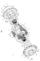
- FIG. 2 is an exploded perspective view of the differential.
- This differential gear 1 is mounted on a vehicle and used to distribute the driving force of the drive source to the first output shaft 91 and the second output shaft 92 while permitting the differential.
- the first output shaft 91 and the second output shaft 92 are indicated by phantom lines.
- the drive source is configured by, for example, an internal combustion engine, an electric motor, or a combination of an engine and an electric motor.
- the differential gear 1 includes a cylindrical first connecting member 2 that rotates together with the first output shaft 91, a cylindrical second connecting member 3 that rotates together with the second output shaft 92, and a first connecting member.
- a first side gear 4 combined with 2 a second side gear 5 combined with a second connecting member 3, a plurality of pinion gear sets 6, a differential case 7 holding a plurality of pinion gear sets 6, and relative rotation to the differential case 7 It is provided with a center washer 80 and a first side washer 81 and a second side washer 82 which are held irreversibly.
- the differential case 7 rotates about the rotation axis O by the driving force of the driving source input from the ring gear 11 .
- the first connecting member 2 , the second connecting member 3 , the first side gear 4 , and the second side gear 5 are rotatable about the rotation axis O relative to the differential case 7 .
- a direction parallel to the rotation axis O will be referred to as an axial direction.
- a direction perpendicular to the rotation axis O is called a radial direction.
- the differential case 7 has a bottomed cylindrical case body 71 and a case lid 72 arranged to close the opening of the case body 71 .
- the case main body 71 includes a cylindrical tubular portion 711, a disk-shaped first side wall portion 712 formed to extend radially inward from one axial end of the tubular portion 711, a first A cylindrical first extension portion 713 extending in the axial direction from the central portion of the side wall portion 712 and a first flange extending radially outward from the end portion of the cylindrical portion 711 on the other side in the axial direction. 714 integrally.
- the first side wall portion 712 is formed with an oil hole 712a for circulating lubricating oil.
- the case lid body 72 includes a disk-shaped second side wall portion 721 , a cylindrical second extension portion 722 axially extending from the central portion of the second side wall portion 721 , and a diameter extending from the second side wall portion 721 . It integrally has a second flange portion 723 formed to protrude outward.
- the second side wall portion 721 is formed with an oil hole 721a for circulating lubricating oil.
- the bolt 12 for fixing the ring gear 11 is inserted through the first flange portion 714 of the case body 71 and the second flange portion 723 of the case lid 72 .
- the differential case 7 and the ring gear 11 are housed in a differential carrier (not shown), and the ring gear 11 meshes with the pinion gear inside the differential carrier.
- Bearings (not shown) are arranged on the outer peripheries of the first extending portion 713 and the second extending portion 722, and the differential case 7 is rotatably supported with respect to the differential carrier by these bearings.
- Lubricating oil (differential oil) is enclosed in the differential carrier.
- the center washer 80 is held by the tubular portion 711 of the case body 71 .
- the first side washer 81 is held by the first side wall portion 712 of the case main body 71
- the second side washer 82 is held by the second side wall portion 721 of the case lid 72 .
- the center washer 80 is arranged between the first side gear 4 and the second side gear 5 .
- the first side washer 81 and the center washer 80 are positioned to sandwich the first connecting member 2 and the first side gear 4 .
- the second side washer 82 is arranged at a position that sandwiches the second connecting member 3 and the second side gear 5 with the center washer 80 .
- the center washer 80, the first side washer 81, and the second side washer 82 have disk-shaped disk portions 801, 811, and 821 and disk-shaped disk portions 801, 811, and 821, respectively. It has a plurality of protrusions 802, 812, 822 protruding radially outward from the outer edge.
- the center washer 80 is restricted from rotating relative to the differential case 7 by engaging the cylindrical portion 711 of the case main body 71 with the plurality of protrusions 802 .
- the first side washer 81 is restricted from rotating relative to the differential case 7 by engaging a plurality of protrusions 812 with the first side wall portion 712 of the case main body 71 .
- the second side washer 82 is restricted from rotating relative to the differential case 7 by engaging the second side wall portion 721 of the case lid 72 with a plurality of protrusions 822 .
- each pinion gear set 6 is configured by meshing one first pinion gear 61 and two second pinion gears 62 .
- the first pinion gear 61 has a large-diameter gear portion 611 and a small-diameter gear portion 612 having different pitch circle diameters.
- the two second pinion gears 62 are shorter in axial length than the first pinion gear 61 and mesh with the small diameter gear portion 612 of the first pinion gear 61 .
- the case body 71 is formed with four bores 70 for holding the four pinion gear sets 6 respectively.
- the inner surface of each bore 70 includes a sliding surface 70a on which the tip of the first pinion gear 61 slides and a sliding surface 70b on which the tip of the second pinion gear 62 slides.
- FIG. 3 shows the first connecting member 2, the second connecting member 3, the first side gear 4, the second side gear 5, the center washer 80, the first side washer 81, and the second side washer 82 spaced apart in the axial direction. It is an explanatory diagram showing
- the first connecting member 2 is formed by protruding radially outward from a cylindrical first cylindrical base portion 21 and an end portion of the first cylindrical base portion 21 on the first side washer 81 side.
- An annular first outer peripheral wall portion 22 and an annular first support wall portion 23 adjacent to the first outer peripheral wall portion 22 and protruding radially outward from the first cylindrical base portion 21 are integrally formed. have.
- a straight spline fitting portion 212 having a plurality of straight spline projections 211 extending in the axial direction is formed on the inner circumference of the first cylindrical base portion 21 .
- a helical spline fitting portion 214 having a plurality of helical spline projections 213 inclined with respect to the axial direction is formed on the outer periphery of the first cylindrical base portion 21 .
- an annular recess 20 is formed for machining the plurality of helical spline projections 213. As shown in FIG.
- the second connecting member 3 protrudes radially outward from a cylindrical second cylindrical base portion 31 and an end portion of the second cylindrical base portion 31 on the side of the second side washer 82 . and a second annular support wall portion 33 formed adjacent to the second outer peripheral wall portion 32 and protruding radially outward from the second cylindrical base portion 31.
- integrally has A straight spline fitting portion 312 having a plurality of straight spline projections 311 extending in the axial direction is formed on the inner circumference of the second cylindrical base portion 31 .
- a helical spline fitting portion 314 having a plurality of helical spline projections 313 inclined with respect to the axial direction is formed on the outer periphery of the second cylindrical base portion 31 .
- an annular recess 30 is formed for machining the plurality of helical spline projections 313. As shown in FIG.
- the first output shaft 91 is inserted inside the first cylindrical base portion 21 and is straight spline-coupled to the plurality of straight spline projections 211 of the straight spline fitting portion 212 .
- the second output shaft 92 is inserted inside the second cylindrical base portion 31 and is straight spline-connected to the plurality of straight spline projections 311 of the straight spline fitting portion 312 .
- the first side gear 4 includes a first cylindrical portion 41 arranged on the outer periphery of the first connecting member 2 and connected to the first connecting member 2 by a helical spline, and one end portion of the first cylindrical portion 41 on the center washer 80 side. It integrally has a first wall portion 42 extending radially inward.
- a helical spline fitting portion 412 having a plurality of helical spline projections 411 inclined with respect to the axial direction is formed on the inner circumference of the first cylindrical portion 41 .
- a helical gear portion 414 having a plurality of helical teeth 413 inclined with respect to the axial direction is formed on the outer periphery of the first cylindrical portion 41 .
- the second side gear 5 includes a second cylindrical portion 51 disposed on the outer periphery of the second connecting member 3 and helically spline-connected to the second connecting member 3, and one side of the second cylindrical portion 51 on the side of the center washer 80. It integrally has a second wall portion 52 extending radially inwardly from the end portion thereof.
- a helical spline fitting portion 512 having a plurality of helical spline projections 511 inclined with respect to the axial direction is formed on the inner circumference of the second cylindrical portion 51 .
- a helical gear portion 514 having a plurality of helical teeth 513 inclined with respect to the axial direction is formed on the outer periphery of the second cylindrical portion 51 .
- the helical spline fitting portion 412 of the first side gear 4 is fitted with the helical spline fitting portion 214 of the first connecting member 2 , and the plurality of helical spline projections 411 of the first side gear 4 and the plurality of helical spline projections 411 of the first connecting member 2 are connected to each other.
- the helical spline protrusion 213 is meshed.
- the helical gear portion 414 of the first side gear 4 meshes with the large diameter gear portion 611 of the first pinion gear 61 .
- the helical spline fitting portion 512 of the second side gear 5 is fitted with the helical spline fitting portion 314 of the second connecting member 3, and the plurality of helical spline projections 511 of the second side gear 5 and the second connecting member 3 are aligned. are meshed with a plurality of helical spline projections 313 of .
- a helical gear portion 514 of the second side gear 5 meshes with the second pinion gear 62 .
- the first outer peripheral wall portion 22 of the first connecting member 2 has an end face 22a on the side of the center washer 80 on the side opposite to the center washer 80 in the first cylindrical portion 41 of the first side gear 4 (first The side washer 81 side) faces the end surface 41a in the axial direction.
- An end face 22a of the first outer peripheral wall portion 22 and an end face 41a of the first cylindrical portion 41 are planes perpendicular to the axial direction.
- An inner peripheral surface 41b of the end portion of the first cylindrical portion 41 of the first side gear 4 on the side of the first side washer 81 radially faces the outer peripheral surface 23a of the first support wall portion 23 of the first connecting member 2 .
- the outer peripheral surface 23 a of the first support wall portion 23 contacts the inner peripheral surface 41 b of the first cylindrical portion 41 , thereby stabilizing the posture of the first side gear 4 with respect to the first connecting member 2 .
- the second outer peripheral wall portion 32 of the second connecting member 3 has an end face 32a on the side of the center washer 80 that is the end face of the second cylindrical portion 51 of the second side gear 5 on the side opposite to the center washer 80 (the side of the second side washer 82). 51a in the axial direction.
- An end face 32a of the second outer peripheral wall portion 32 and an end face 51a of the second cylindrical portion 51 are planes perpendicular to the axial direction.
- the inner peripheral surface 51b of the end portion of the second cylindrical portion 51 of the second side gear 5 on the side of the second side washer 82 radially faces the outer peripheral surface 33a of the second support wall portion 33 of the second connecting member 3 .
- the outer peripheral surface 33 a of the second support wall portion 33 contacts the inner peripheral surface 51 b of the second cylindrical portion 51 , thereby stabilizing the posture of the second side gear 5 with respect to the second connecting member 3 .
- the surface of the first connecting member 2 on the side of the first side washer 81 is composed of a contact surface 2a that generates frictional force through frictional contact with the first side washer 81 and a non-contact surface 2b that does not contact the first side washer 81. contains.
- the contact surface 2a and the non-contact surface 2b are annular planes perpendicular to the axial direction, and the contact surface 2a is formed on the outer peripheral side of the non-contact surface 2b.
- the contact surface 2a protrudes toward the first side washer 81 from the non-contact surface 2b.
- An end surface 21a of the first cylindrical base portion 21 of the first connecting member 2 on the side of the center washer 80 faces the first wall portion 42 of the first side gear 4 in the axial direction.
- the surface of the second connecting member 3 on the side of the second side washer 82 includes a contact surface 3a that generates frictional force by frictional contact with the second side washer 82, and a non-contact surface that does not contact the second side washer 82. surface 3b.
- the contact surface 3a and the non-contact surface 3b are annular planes perpendicular to the axial direction, and the contact surface 3a is formed on the outer peripheral side of the non-contact surface 3b.
- the contact surface 3a protrudes toward the second side washer 82 from the non-contact surface 3b.
- An end surface 31a of the second cylindrical base portion 31 of the second connecting member 3 on the side of the center washer 80 faces the second wall portion 52 of the second side gear 5 in the axial direction.
- the first wall portion 42 of the first side gear 4 protrudes radially inward beyond the plurality of straight spline projections 211 of the first connecting member 2 .
- the first output shaft 91 is inserted inside the first extending portion 713 of the differential case 7 and the first connecting member 2 during assembly of the vehicle in which the differential gear 1 is mounted, and is inserted into the first wall of the first side gear 4 . It hits the part 42 .
- a through hole 420 that axially penetrates the first wall portion 42 is formed in the center of the first side gear 4 . As shown in FIG.
- a first opposing surface 42a facing the end surface 21a of the first cylindrical base portion 21 of the first connecting member 2 and a first It includes a first contact surface 42b with which the tip surface 91a (see FIG. 1) of the output shaft 91 contacts.
- the first contact surface 42 b is formed on a portion of the first wall portion 42 protruding radially inward from the plurality of straight spline projections 211 of the first connecting member 2 .
- the first abutment surface 42b is subjected to finish processing for increasing the dimensional accuracy of the first output shaft 91 when the tip surface 91a of the first output shaft 91 abuts against it.
- the first contact surface 42b is slightly offset toward the center washer 80 with respect to the first opposing surface 42a.
- the second wall portion 52 of the second side gear 5 protrudes radially inward beyond the plurality of straight spline projections 311 of the second connecting member 3 .
- the second output shaft 92 is inserted inside the second extending portion 722 of the differential case 7 and the second connecting member 3 during assembly of the vehicle in which the differential gear 1 is mounted, and is inserted into the second wall of the second side gear 5 . It hits the part 52 .
- a through hole 520 is formed in the center of the second side gear 5 so as to axially penetrate through the second wall portion 52 . As shown in FIG.
- the surface of the second wall portion 52 of the second side gear 5 opposite to the center washer 80 has a second facing surface 52a facing the end surface 31a of the second cylindrical base portion 31 of the second connecting member 3, and a second A second abutment surface 52b with which the tip surface 92a (see FIG. 1) of the output shaft 92 abuts is included.
- the second contact surface 52 b is formed on a portion of the second wall portion 52 protruding radially inward from the plurality of straight spline projections 311 of the second connecting member 3 .
- the second abutment surface 52b is subjected to finish processing for increasing the dimensional accuracy of the second output shaft 92 when the tip surface 92a of the second output shaft 92 abuts against it.
- the second contact surface 52b is slightly offset toward the center washer 80 with respect to the second opposing surface 52a.
- the first output shaft 91 is temporarily abutted against the first wall portion 42 of the first side gear 4 when assembling the vehicle. It is positioned at a spaced apart position and does not contact the first wall portion 42 .
- the second output shaft 92 is temporarily abutted against the second wall portion 52 of the second side gear 5 during assembly of the vehicle, but when the assembly is completed, the second output shaft 92 extends from the second wall portion 52 of the second side gear 5 in the axial direction. , and does not contact the second wall portion 52 .
- directions of axial thrust forces F 11 to F 16 generated in the first connecting member 2, the second connecting member 3, the first side gear 4, and the second side gear 5 during driving are indicated by black arrows. showing.
- directions of axial thrust forces F 21 to F 26 generated in the first connecting member 2, the second connecting member 3, the first side gear 4, and the second side gear 5 during coasting are indicated by white lines. indicated by an arrow.
- the meshing between the helical gear portion 414 of the first side gear 4 and the large diameter gear portion 611 of the first pinion gear 61 generates a thrust force F11 toward the center washer 80 in the first side gear 4 and the second side gear.
- a thrust force F12 toward the center washer 80 is generated in the second side gear 5 by the meshing of the helical gear portion 514 of 5 and the second pinion gear 62 .
- the engagement between the helical spline fitting portion 412 of the first side gear 4 and the helical spline fitting portion 214 of the first connecting member 2 causes the first side gear 4 to exert a thrust force F13 toward the center washer 80 side. is generated, a thrust force F 14 toward the first side washer 81 is generated in the first connecting member 2 .
- the engagement between the helical spline fitting portion 512 of the second side gear 5 and the helical spline fitting portion 314 of the second connecting member 3 causes the second side gear 5 to exert a thrust force F toward the center washer 80 side. 15 is generated, a thrust force F 16 toward the second side washer 82 is generated in the second connecting member 3 .
- the surface of the first wall portion 42 of the first side gear 4 on the side of the center washer 80 is formed with an abutment surface 42c that faces the center washer 80 in the axial direction and abuts against the center washer 80 during driving.
- a surface of the second wall portion 52 of the second side gear 5 on the side of the center washer 80 is formed with a contact surface 52c that faces the center washer 80 in the axial direction and contacts the center washer 80 during driving.
- the center washer 80 controls the thrust force F 11 generated in the first side gear 4 due to the engagement between the first side gear 4 and the first pinion gear 61 and the helical spline connection between the first side gear 4 and the first connecting member 2 .
- Frictional force is generated between the first side gear 4 and the first wall portion 42 by the thrust force F13 generated in the first side gear 4 by .
- center washer 80 also acts as a thrust force F 12 generated in the second side gear 5 due to the engagement between the second side gear 5 and the second pinion gear 62 and a helical force between the second side gear 5 and the second connecting member 3 during driving.
- a frictional force is generated between the second side gear 5 and the second wall portion 52 by the thrust force F15 generated in the second side gear 5 by the spline connection.
- the first side washer 81 is interposed between itself and the first connecting member 2 by a thrust force F14 generated in the first connecting member 2 by the helical spline connection between the first side gear 4 and the first connecting member 2. generate frictional force.
- the second side washer 82 is interposed between itself and the second connecting member 3 by a thrust force F16 generated in the second connecting member 3 due to the helical spline connection between the second side gear 5 and the second connecting member 3. generate frictional force. Frictional forces generated by these thrust forces F 11 to F 16 serve as differential limiting forces that suppress differential rotation between the first output shaft 91 and the second output shaft 92 during driving.
- the engagement between the first side gear 4 and the first pinion gear 61 generates a thrust force F21 in the first side gear 4 toward the first side washer 81 side.
- the first outer peripheral wall portion 22 of the first connecting member 2 receives this thrust force F21 from the end surface 41a of the first cylindrical portion 41, and the contact surface 2a of the first connecting member 2 contacts the first side washer 81. frictional force is generated.
- the thrust force F23 and the thrust force F24 generated in the first side gear 4 and the first connecting member 2 due to the helical spline connection between the first side gear 4 and the first connecting member 2 are generated by the first cylinder of the first side gear 4.
- the engagement between the second side gear 5 and the second pinion gear 62 generates a thrust force F22 in the second side gear 5 toward the second side washer 82 side.
- the second outer peripheral wall portion 32 of the second connecting member 3 receives this thrust force F22 from the end surface 51a of the second cylindrical portion 51, and the contact surface 3a of the second connecting member 3 contacts the second side washer 82. frictional force is generated.
- the thrust force F25 and the thrust force F26 generated in the second side gear 5 and the second connecting member 3 due to the helical spline connection between the second side gear 5 and the second connecting member 3 are When the end face 51a of the portion 51 contacts the end face 32a of the second outer peripheral wall portion 32 of the second connecting member 3, they cancel each other out.
- the thrust force F11 generated by the engagement between the first side gear 4 and the first pinion gear 61 and the thrust force F13 generated by the helical spline connection between the first side gear 4 and the first connecting member 2 generate the first side gear.
- 4 of the first wall portion 42 is pressed against the center washer 80 . Therefore, if the contact area between the first side gear 4 and the center washer 80 is small, the contact surface is likely to generate heat and wear.
- the contact surface 42c of the first wall portion 42 which protrudes radially inward from the plurality of straight spline projections 211 of the first connecting member 2 and contacts the center washer 80, is ensured to be large. As a result, heat generation and wear due to friction between the first wall portion 42 of the first side gear 4 and the center washer 80 are suppressed.
- the resultant force of the thrust force F21 generated by the engagement between the second side gear 5 and the second pinion gear 62 and the thrust force F25 generated by the helical spline connection between the second side gear 5 and the second connecting member 3 causes the second The second wall portion 52 of the two-side gear 5 is pressed against the center washer 80 .
- the second wall portion 52 of the second side gear 5 protrudes radially inwardly beyond the plurality of straight spline projections 311 of the second connecting member 3 , and the second wall portion 52 contacts the center washer 80 .
- a large surface 52c is ensured. As a result, heat generation and wear due to friction between the second wall portion 52 of the second side gear 5 and the center washer 80 are suppressed.
- the through hole 420 of the first side gear 4 and the through hole 520 of the second side gear 5 function as oil holes through which lubricating oil flows inside the differential case 7 .
- the inner diameter D 0 of the center washer 80 is larger than the inner diameter D 11 of the through hole 420 and the inner diameter D 21 of the through hole 520, and is a size that does not hinder the flow of lubricating oil through the through holes 420 and 520 .
- the through hole 420 of the first side gear 4 and the through hole 520 of the second side gear 5 are formed when the plurality of helical spline projections 411 and 511 are cut during manufacturing of the first side gear 4 and the second side gear 5. It is also used to discharge the chips that are generated.
- the inner diameter D 0 of the center washer 80 is smaller than the inner diameter D 12 of the straight spline fitting portion 212 of the first connecting member 2 and the inner diameter D 22 of the straight spline fitting portion 312 of the second connecting member 3 . This ensures a large contact area between the first wall portion 42 of the first side gear 4 and the second wall portion 52 of the second side gear 5 and the center washer 80 .
- the axial length between the end surface 21a of the first cylindrical base portion 21 and the end surface 22a of the first outer peripheral wall portion 22 in the first connecting member 2 is defined as L11
- the first side gear 4 When the axial length between the end surface 41a of the first cylindrical portion 41 and the first opposing surface 42a of the first wall portion 42 at is L12 , L12 is longer than L11 .
- a gap is always formed between the end surface 21 a of the first cylindrical base portion 21 and the first opposing surface 42 a of the first wall portion 42 , and the first connecting member 2 is connected to the first wall of the first side gear 4 .
- the end surface 21a of the first cylindrical base portion 21 and the first opposing surface 42a of the first wall portion 42 do not need to be subjected to turning processing or the like, and for example, the forged surface may be left as it is.
- the axial length between the end surface 31a of the second cylindrical base portion 31 and the end surface 32a of the second outer peripheral wall portion 32 in the third connecting member 3 is defined as L21
- the second cylinder in the second side gear 5 Assuming that the axial length between the end surface 51a of the portion 51 and the second opposing surface 52a of the second wall portion 52 is L22 , L22 is longer than L21 .
- a gap is always formed between the end surface 31 a of the second cylindrical base portion 31 and the second opposing surface 52 a of the second wall portion 52 , and the second connecting member 3 is connected to the second wall of the second side gear 5 .
- the end surface 31a of the second cylindrical base portion 31 and the second facing surface 52a of the second wall portion 52 do not need to be subjected to lathe turning or the like, and may be left as they are, for example.
- FIG. 4 is a cross-sectional view showing a differential gear 1A according to a comparative example.
- the first side gear 4 is not provided with the first wall portion 42
- the second side gear 5 is not provided with the second wall portion 52 .
- the first connecting member 2 is provided with a first wall portion 24 extending radially inward from the end portion of the first cylindrical base portion 21 on the side of the center washer 80
- the second connecting member 3 is provided with a second cylindrical base portion 31 .
- a second wall portion 34 is provided extending radially inward from the end portion of the center washer 80 side. Since the rest of the configuration is the same as the configuration of the differential gear 1 according to the above-described embodiment, in FIG. to omit redundant description.
- the first output shaft 91 abuts against the first wall portion 24 of the first connecting member 2, and the second output shaft 91 hits the second wall portion 34 of the third connecting member 3. It is possible to abut the output shaft 92 .
- the contact area between the first side gear 4 and the second side gear 5 and the center washer 80 during driving is smaller than in the case of the differential gear 1 according to the embodiment.
- the contact surface with the center washer 80 is likely to generate heat and wear.
- the first wall portion 24 and the second wall portion 34 do not exhibit any function after the vehicle is assembled.
- the first side gear 4 is provided with the first wall portion 42
- the second side gear 5 is provided with the second wall portion 52. Positioning of the first output shaft 91 and the second output shaft 92 at the time of assembly can be easily performed, and the first side gear 4 and the second side gear 5 and the center washer 80 can be easily positioned by the first wall portion 42 and the second wall portion 52. It is possible to increase the contact area with and suppress heat generation and wear.
- the through hole 420 of the first side gear 4 and the through hole 520 of the second side gear 5 function as oil holes through which lubricating oil flows in the differential case 7. Heat generation and wear of the friction sliding portion of the differential case 7 are suppressed by the improved lubricity.
- the first connecting member 2 does not contact the first wall portion 42 of the first side gear 4
- the second connecting member 3 does not contact the first wall portion 42 of the second side gear 5 . Since the second wall portion 52 is not contacted, the end surface 21a of the first cylindrical base portion 21, the end surface 31a of the second cylindrical base portion 31, the first opposing surface 42a of the first wall portion 42, and the second wall portion 52 Machining of the second opposing surface 52a can be omitted, and the machining cost can be reduced.
Landscapes
- Engineering & Computer Science (AREA)
- General Engineering & Computer Science (AREA)
- Mechanical Engineering (AREA)
- Retarders (AREA)
Abstract
Description
本発明の実施の形態について、図1乃至図3を参照して説明する。なお、以下に説明する実施の形態は、本発明を実施する上での好適な具体例として示すものであり、技術的に好ましい種々の技術的事項を具体的に例示している部分もあるが、本発明の技術的範囲は、この具体的態様に限定されるものではない。
以上、本発明を実施の形態に基づいて説明したが、この実施の形態は請求の範囲に係る発明を限定するものではない。また、実施の形態の中で説明した特徴の組合せの全てが発明の課題を解決するための手段に必須であるとは限らない点に留意すべきである。また、本発明は、その趣旨を逸脱しない範囲で、一部の構成を省略し、あるいは構成を追加もしくは置換して、適宜変形して実施することが可能である。
2…第1連結部材
21…第1筒状基体部
211…ストレートスプライン突起
213…ヘリカルスプライン突起
22…第1外周壁部
22a…端面
3…第2連結部材
31…第2筒状基体部
311…ストレートスプライン突起
313…ヘリカルスプライン突起
32…第2外周壁部
32a…端面
4…第1サイドギヤ
41…第1円筒部
41a…端面
411…ヘリカルスプライン突起
42…第1壁部
420…貫通孔
5…第2サイドギヤ
51…第2円筒部
51a…端面
511…ヘリカルスプライン突起
52…第2壁部
520…貫通孔
6…ピニオンギヤ組
61…第1ピニオンギヤ
62…第2ピニオンギヤ
7…デフケース
80…センタワッシャ
91…第1出力軸
92…第2出力軸
Claims (3)
- 車両の駆動力を第1出力軸及び第2出力軸に配分する差動装置であって、
前記第1出力軸がストレートスプライン結合される複数のストレートスプライン突起を内周に有する円筒状の第1連結部材と、
前記第2出力軸がストレートスプライン結合される複数のストレートスプライン突起を内周に有する円筒状の第2連結部材と、
前記第1連結部材と組み合わされた第1サイドギヤと、
前記第2連結部材と組み合わされた第2サイドギヤと、
前記第1サイドギヤに噛み合う第1ピニオンギヤと前記第2サイドギヤに噛み合う第2ピニオンギヤとを噛み合わせてなる複数のピニオンギヤ組と、
前記複数のピニオンギヤ組を保持するデフケースと、
前記第1サイドギヤと前記第2サイドギヤとの間に配置され、前記デフケースとの相対回転が規制されたセンタワッシャと、を備え、
前記第1サイドギヤは、前記第1連結部材の外周に配置されて前記第1連結部材とヘリカルスプライン結合された第1円筒部と、前記第1円筒部の前記センタワッシャ側の一方の端部から内径側に延びる第1壁部とを有し、前記第1壁部が前記第1連結部材の前記複数のストレートスプライン突起よりも内径側に突出しており、
前記第2サイドギヤは、前記第2連結部材の外周に配置されて前記第2連結部材とヘリカルスプライン結合された第2円筒部と、前記第2円筒部の前記センタワッシャ側の一方の端部から内径側に延びる第2壁部とを有し、前記第2壁部が前記第2連結部材の前記複数のストレートスプライン突起よりも内径側に突出しており、
前記センタワッシャは、前記第1サイドギヤ及び前記第2サイドギヤから前記第1連結部材及び前記第2連結部材にトルクが伝達されるドライブ時に、前記ヘリカルスプライン結合によって発生するスラスト力によって前記第1サイドギヤの前記第1壁部及び前記第2サイドギヤの前記第2壁部との間に摩擦力を発生させる、
差動装置。 - 前記第1サイドギヤの中心部に前記第1壁部を軸方向に貫通する貫通孔が形成され、
前記第2サイドギヤの中心部に前記第2壁部を軸方向に貫通する貫通孔が形成された、
請求項1に記載の差動装置。 - 前記第1連結部材は、前記第1サイドギヤの前記第1円筒部における前記センタワッシャとは反対側の端面と軸方向に対向する環状の第1外周壁部を有し、
前記第2連結部材は、前記第2サイドギヤの前記第2円筒部における前記センタワッシャとは反対側の端面と軸方向に対向する環状の第2外周壁部を有し、
前記第1連結部材及び前記第2連結部材から前記第1サイドギヤ及び前記第2サイドギヤにトルクが伝達されるコースト時に、前記第1円筒部の前記端面と前記第1外周壁部とが当接すると共に、前記第2円筒部の前記端面と前記第2外周壁部とが当接し、前記第1連結部材と前記第1壁部は当接せず、前記第2連結部材と前記第2壁部も当接しない、
請求項1又は2に記載の差動装置。
Priority Applications (5)
| Application Number | Priority Date | Filing Date | Title |
|---|---|---|---|
| PCT/JP2021/043840 WO2023100239A1 (ja) | 2021-11-30 | 2021-11-30 | 差動装置 |
| DE112021008483.6T DE112021008483T5 (de) | 2021-11-30 | 2021-11-30 | Differenzialgetriebe |
| JP2023564297A JP7622874B2 (ja) | 2021-11-30 | 2021-11-30 | 差動装置 |
| CN202180104517.3A CN118302616A (zh) | 2021-11-30 | 2021-11-30 | 差动装置 |
| US18/709,894 US12410853B2 (en) | 2021-11-30 | 2021-11-30 | Differential gear |
Applications Claiming Priority (1)
| Application Number | Priority Date | Filing Date | Title |
|---|---|---|---|
| PCT/JP2021/043840 WO2023100239A1 (ja) | 2021-11-30 | 2021-11-30 | 差動装置 |
Publications (1)
| Publication Number | Publication Date |
|---|---|
| WO2023100239A1 true WO2023100239A1 (ja) | 2023-06-08 |
Family
ID=86611747
Family Applications (1)
| Application Number | Title | Priority Date | Filing Date |
|---|---|---|---|
| PCT/JP2021/043840 Ceased WO2023100239A1 (ja) | 2021-11-30 | 2021-11-30 | 差動装置 |
Country Status (5)
| Country | Link |
|---|---|
| US (1) | US12410853B2 (ja) |
| JP (1) | JP7622874B2 (ja) |
| CN (1) | CN118302616A (ja) |
| DE (1) | DE112021008483T5 (ja) |
| WO (1) | WO2023100239A1 (ja) |
Citations (2)
| Publication number | Priority date | Publication date | Assignee | Title |
|---|---|---|---|---|
| JP2021134806A (ja) * | 2020-02-25 | 2021-09-13 | 本田技研工業株式会社 | 車両用差動装置 |
| JP2021173389A (ja) * | 2020-04-30 | 2021-11-01 | 株式会社ジェイテクト | 車両用差動装置 |
Family Cites Families (5)
| Publication number | Priority date | Publication date | Assignee | Title |
|---|---|---|---|---|
| US3375736A (en) * | 1966-09-15 | 1968-04-02 | Illinois Tool Works | Differential mechanism |
| JP5018505B2 (ja) * | 2008-01-22 | 2012-09-05 | 株式会社ジェイテクト | 車両用差動歯車装置 |
| JP2015145703A (ja) * | 2014-02-03 | 2015-08-13 | 武蔵精密工業株式会社 | 差動装置 |
| JP6481261B2 (ja) | 2014-04-16 | 2019-03-13 | 株式会社ジェイテクト | 車両用差動装置 |
| JP6565524B2 (ja) * | 2015-09-17 | 2019-08-28 | 株式会社ジェイテクト | 車両用差動装置 |
-
2021
- 2021-11-30 JP JP2023564297A patent/JP7622874B2/ja active Active
- 2021-11-30 CN CN202180104517.3A patent/CN118302616A/zh active Pending
- 2021-11-30 DE DE112021008483.6T patent/DE112021008483T5/de active Pending
- 2021-11-30 WO PCT/JP2021/043840 patent/WO2023100239A1/ja not_active Ceased
- 2021-11-30 US US18/709,894 patent/US12410853B2/en active Active
Patent Citations (2)
| Publication number | Priority date | Publication date | Assignee | Title |
|---|---|---|---|---|
| JP2021134806A (ja) * | 2020-02-25 | 2021-09-13 | 本田技研工業株式会社 | 車両用差動装置 |
| JP2021173389A (ja) * | 2020-04-30 | 2021-11-01 | 株式会社ジェイテクト | 車両用差動装置 |
Also Published As
| Publication number | Publication date |
|---|---|
| CN118302616A (zh) | 2024-07-05 |
| JPWO2023100239A1 (ja) | 2023-06-08 |
| US20250027557A1 (en) | 2025-01-23 |
| JP7622874B2 (ja) | 2025-01-28 |
| DE112021008483T5 (de) | 2024-12-19 |
| US12410853B2 (en) | 2025-09-09 |
Similar Documents
| Publication | Publication Date | Title |
|---|---|---|
| US10300780B2 (en) | Support structure for rotating shafts of vehicle | |
| CN104048012B (zh) | 包括具有嵌套环形齿轮的行星变速器的驱动模块 | |
| US10794460B2 (en) | Differential device | |
| JP6565524B2 (ja) | 車両用差動装置 | |
| US10788097B2 (en) | Friction damper | |
| US10093180B2 (en) | Transfer device for four-wheel drive vehicle | |
| CN101595329A (zh) | 车辆用差速装置 | |
| JP7396187B2 (ja) | 車両用差動装置 | |
| CN111322372B (zh) | 车辆差动装置 | |
| US11204085B2 (en) | Vehicle differential apparatus | |
| CN107202154A (zh) | 驱动装置的轴支承构造 | |
| WO2023100239A1 (ja) | 差動装置 | |
| US11028914B2 (en) | Vehicle differential device | |
| JP4540253B2 (ja) | 車両用動力伝達装置 | |
| JP6587975B2 (ja) | 回転部材の支持構造 | |
| JP2006266373A (ja) | デファレンシャル装置 | |
| CA2766059A1 (en) | Gear set for differential | |
| JPH0868453A (ja) | デファレンシャル装置 | |
| JP2008196681A (ja) | 軸受構造および変速機 | |
| JP6502833B2 (ja) | ハイブリッド車両の軸支持構造 | |
| JP7850771B2 (ja) | デファレンシャル装置 | |
| JP7484748B2 (ja) | 自動変速機 | |
| JP2026006097A (ja) | 差動歯車装置 | |
| JP2024134875A (ja) | 遊星歯車機構およびその製造方法 | |
| JP6410706B2 (ja) | 回転体の支持構造 |
Legal Events
| Date | Code | Title | Description |
|---|---|---|---|
| 121 | Ep: the epo has been informed by wipo that ep was designated in this application |
Ref document number: 21966325 Country of ref document: EP Kind code of ref document: A1 |
|
| WWE | Wipo information: entry into national phase |
Ref document number: 2023564297 Country of ref document: JP |
|
| WWE | Wipo information: entry into national phase |
Ref document number: 18709894 Country of ref document: US |
|
| WWE | Wipo information: entry into national phase |
Ref document number: 202180104517.3 Country of ref document: CN |
|
| WWE | Wipo information: entry into national phase |
Ref document number: 112021008483 Country of ref document: DE |
|
| 122 | Ep: pct application non-entry in european phase |
Ref document number: 21966325 Country of ref document: EP Kind code of ref document: A1 |
|
| WWG | Wipo information: grant in national office |
Ref document number: 18709894 Country of ref document: US |