WO2023095723A1 - 顕微鏡対物レンズ、顕微鏡光学系、および顕微鏡装置 - Google Patents
顕微鏡対物レンズ、顕微鏡光学系、および顕微鏡装置 Download PDFInfo
- Publication number
- WO2023095723A1 WO2023095723A1 PCT/JP2022/042845 JP2022042845W WO2023095723A1 WO 2023095723 A1 WO2023095723 A1 WO 2023095723A1 JP 2022042845 W JP2022042845 W JP 2022042845W WO 2023095723 A1 WO2023095723 A1 WO 2023095723A1
- Authority
- WO
- WIPO (PCT)
- Prior art keywords
- lens
- microscope objective
- objective lens
- lens group
- microscope
- Prior art date
- Legal status (The legal status is an assumption and is not a legal conclusion. Google has not performed a legal analysis and makes no representation as to the accuracy of the status listed.)
- Ceased
Links
Images




Classifications
-
- G—PHYSICS
- G02—OPTICS
- G02B—OPTICAL ELEMENTS, SYSTEMS OR APPARATUS
- G02B21/00—Microscopes
- G02B21/02—Objectives
-
- G—PHYSICS
- G02—OPTICS
- G02B—OPTICAL ELEMENTS, SYSTEMS OR APPARATUS
- G02B21/00—Microscopes
- G02B21/0004—Microscopes specially adapted for specific applications
- G02B21/002—Scanning microscopes
- G02B21/0024—Confocal scanning microscopes (CSOMs) or confocal "macroscopes"; Accessories which are not restricted to use with CSOMs, e.g. sample holders
-
- G—PHYSICS
- G02—OPTICS
- G02B—OPTICAL ELEMENTS, SYSTEMS OR APPARATUS
- G02B27/00—Optical systems or apparatus not provided for by any of the groups G02B1/00 - G02B26/00, G02B30/00
- G02B27/0025—Optical systems or apparatus not provided for by any of the groups G02B1/00 - G02B26/00, G02B30/00 for optical correction, e.g. distorsion, aberration
-
- G—PHYSICS
- G02—OPTICS
- G02B—OPTICAL ELEMENTS, SYSTEMS OR APPARATUS
- G02B9/00—Optical objectives characterised both by the number of the components and their arrangements according to their sign, i.e. + or -
- G02B9/60—Optical objectives characterised both by the number of the components and their arrangements according to their sign, i.e. + or - having five components only
Definitions
- the present invention relates to microscope objective lenses, microscope optical systems, and microscope devices.
- Patent Document 1 various objective lenses for microscopes with wide fields of view and low magnification have been proposed (see Patent Document 1, for example).
- Such an objective lens is required to satisfactorily correct various aberrations such as curvature of field.
- a microscope objective lens comprises a first lens group having a positive refractive power, a second lens group having a negative refractive power, and a positive refractive power, which are arranged in order from the object side along an optical axis.
- the first lens group converges the light flux from the object
- the second lens group diverges the light flux from the first lens group
- the third lens group has , a cemented lens including a positive lens and a negative lens, converts a divergent light beam from the second lens group into a parallel light beam, and satisfies the following conditional expression.
- tg the sum of the center thicknesses of the lenses in the microscope objective lens
- LA the distance on the optical axis from the lens surface closest to the object side to the lens surface closest to the image side of the microscope objective lens
- ⁇ d3P the thickness of the third lens group
- vd3N Abbe number of the negative lens in the cemented lens of the third lens group
- a microscope optical system includes the microscope objective lens described above and a second objective lens that collects light from the microscope objective lens.
- a microscope apparatus includes the microscope objective lens described above.
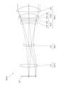
- FIG. 1 is a cross-sectional view showing the configuration of a microscope objective lens according to a first example
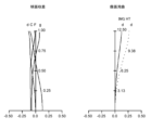
- FIG. FIG. 2 is a diagram of various aberrations of the microscope objective lens according to the first example
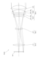
- FIG. 5 is a cross-sectional view showing the configuration of a microscope objective lens according to a second example
- FIG. 10 is a diagram showing various aberrations of the microscope objective lens according to the second example
- FIG. 11 is a cross-sectional view showing the configuration of a microscope objective lens according to a third example
- FIG. 10 is a diagram of various aberrations of the microscope objective lens according to the third example
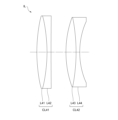
- FIG. 4 is a cross-sectional view showing the configuration of a second objective lens
- 1 is a schematic configuration diagram showing a confocal fluorescence microscope as an example of a microscope apparatus
- the confocal fluorescence microscope 1 includes a stage 10, a light source 20, an illumination optical system 30, a microscope optical system 40, and a detector 50.
- the coordinate axis extending in the optical axis direction of the microscope objective lens of the confocal fluorescence microscope 1 is the z-axis. Coordinate axes extending in directions perpendicular to each other in a plane perpendicular to the z-axis are defined as x-axis and y-axis, respectively.
- a sample SA held between, for example, a slide glass (not shown) and a cover glass (not shown) is placed on the stage 10 .
- the sample SA accommodated in a sample container (not shown) together with the immersion liquid may be placed on the stage 10 .
- the sample SA contains a fluorescent substance such as a fluorescent dye.
- the sample SA is, for example, cells that have been previously fluorescently stained.
- a stage drive unit 11 is provided near the stage 10 .
- a stage drive unit 11 moves the stage 10 along the z-axis.
- the light source 20 generates excitation light in a predetermined wavelength band.
- the light source 20 for example, a laser light source or the like capable of emitting laser light (excitation light) in a predetermined wavelength band is used.
- the predetermined wavelength band is set to a wavelength band that can excite the sample SA containing the fluorescent substance.
- the excitation light emitted from the light source 20 enters the illumination optical system 30 .
- the illumination optical system 30 illuminates the sample SA on the stage 10 with excitation light emitted from the light source 20 .
- the illumination optical system 30 includes a collimator lens 31, a beam splitter 33, and a scanner 34 in order from the light source 20 side toward the sample SA side.
- the illumination optical system 30 also includes the microscope objective lens OL of the microscope optical system 40 .
- the collimator lens 31 collimates the excitation light emitted from the light source 20 .
- the beam splitter 33 has the characteristic of reflecting the excitation light from the light source 20 and transmitting the fluorescence from the sample SA.
- the beam splitter 33 reflects excitation light from the light source 20 toward the sample SA on the stage 10 .
- the beam splitter 33 transmits fluorescence generated in the sample SA toward the detection unit 50 .
- An excitation filter 32 is arranged between the beam splitter 33 and the collimator lens 31 to transmit the excitation light from the light source 20 .
- a fluorescence filter 35 is arranged between the beam splitter 33 and the second objective lens IL of the microscope optical system 40 to transmit fluorescence from the sample SA.
- the scanner 34 scans the sample SA with excitation light from the light source 20 in two directions, i.e., the x direction and the y direction.
- the scanner 34 for example, a galvanometer scanner, a resonant scanner, or the like is used.
- the microscope optical system 40 collects fluorescence generated in the sample SA.
- the microscope optical system 40 includes a microscope objective lens OL and a second objective lens IL in order from the sample SA side to the detection unit 50 side.
- the microscope optical system 40 also includes a scanner 34 and a beam splitter 33 arranged between the microscope objective lens OL and the second objective lens IL.
- the microscope objective lens OL is arranged facing above the stage 10 on which the sample SA is placed.
- the microscope objective lens OL condenses the excitation light from the light source 20 and irradiates the sample SA on the stage 10 with it. Further, the microscope objective lens OL receives the fluorescence generated in the sample SA and converts it into parallel light.
- the second objective lens IL collects fluorescence (parallel light) from the microscope objective lens OL.
- the detection unit 50 detects fluorescence generated in the sample SA via the microscope optical system 40.
- a photomultiplier tube for example, is used as the detector 50 .
- a pinhole 45 is provided between the microscope optical system 40 and the detection unit 50 .
- the pinhole 45 is arranged at a position conjugate with the focal position of the microscope objective lens OL on the sample SA side.
- the pinhole 45 is formed on the focal plane of the microscope objective lens OL (the plane passing through the focal position of the microscope objective lens OL and perpendicular to the optical axis of the microscope objective lens OL), or within a predetermined deviation tolerance from the focal plane in the optical axis direction. Only the light from the misaligned surface is allowed to pass through and the other light is blocked.
- the excitation light emitted from the light source 20 passes through the collimator lens 31 and becomes parallel light.
- the excitation light transmitted through the collimator lens 31 passes through the excitation filter 32 and enters the beam splitter 33 .
- the excitation light incident on the beam splitter 33 is reflected by the beam splitter 33 and enters the scanner 34 .
- the scanner 34 scans the sample SA with the excitation light incident on the scanner 34 in two directions, the x direction and the y direction.
- the excitation light incident on the scanner 34 passes through the scanner 34 and the microscope objective lens OL, and is focused on the focal plane of the microscope objective lens OL.
- a portion of the sample SA where the excitation light is condensed (that is, a portion overlapping with the focal plane of the microscope objective lens OL) is two-dimensionally scanned by the scanner 34 in two directions of the x direction and the y direction.
- the illumination optical system 30 illuminates the sample SA on the stage 10 with the excitation light emitted from the light source 20 .
- the irradiation of the excitation light excites the fluorescent substance contained in the sample SA and emits fluorescence. Fluorescence from the sample SA passes through the microscope objective lens OL and becomes parallel light. Fluorescence transmitted through the microscope objective lens OL enters the beam splitter 33 through the scanner 34 . The fluorescence incident on the beam splitter 33 is transmitted through the beam splitter 33 and reaches the fluorescence filter 35 . The fluorescence that reaches the fluorescence filter 35 passes through the fluorescence filter 35, passes through the second objective lens IL, and is condensed at a position conjugate with the focal position of the microscope objective lens OL. The fluorescence condensed at a position conjugate with the focal position of the microscope objective lens OL passes through the pinhole 45 and enters the detector 50 .
- the detection unit 50 photoelectrically converts the light (fluorescence) incident on the detection unit 50, and generates data corresponding to the light amount (brightness) of the light as a light detection signal.
- the detection unit 50 outputs the generated data to a control unit (not shown).
- the control unit treats the data input from the detection unit 50 as data for one pixel, and arranges the data in synchronization with the two-dimensional scanning by the scanner 34, so that the data for a plurality of pixels is divided into two. Generate a piece of image data that is dimensionally aligned (in two directions). In this way, the controller can acquire an image of the sample SA.
- the confocal fluorescence microscope 1 has been described as an example of the microscope apparatus according to this embodiment, it is not limited to this.
- the microscope apparatus according to this embodiment may be an observation microscope for performing bright-field observation, fluorescence observation, or the like, a confocal microscope, a multiphoton excitation microscope, a super-resolution microscope, or the like.
- the confocal fluorescence microscope 1 may be an upright microscope or an inverted microscope.
- the microscope objective lens according to this embodiment will be described.
- the microscope objective lens OL (1) shown in FIG. a second lens group G2 having negative refractive power and a third lens group G3 having positive refractive power.
- the first lens group G1 converges the light flux from the object.
- the second lens group G2 diverges the light flux from the first lens group G1.
- the third lens group G3 has a cemented lens including a positive lens and a negative lens, and converts the divergent light flux from the second lens group G2 into a parallel light flux.
- the fact that the first lens group G1 converges the light flux from the object means that the first lens group G1 has a condensing function. For example, when a divergent luminous flux from an object passes through the first lens group G1, the luminous flux from the first lens group G1 may become a divergent luminous flux whose degree of divergence is weakened by the first lens group G1.
- the microscope objective lens OL satisfies the following conditional expressions (1) and (2). 0.1 ⁇ tg/LA ⁇ 0.4 (1) ⁇ 35 ⁇ d3P ⁇ d3N ⁇ 0 (2) where tg: sum of central thicknesses of lenses in the microscope objective lens OL LA: distance on the optical axis from the lens surface closest to the object side of the microscope objective lens OL to the lens surface closest to the image side of the microscope objective lens OL ⁇ d3P: th Abbe number of the positive lens in the cemented lens of the third lens group G3 ⁇ d3N: Abbe number of the negative lens in the cemented lens of the third lens group G3
- the microscope objective lens OL may be the optical system OL(2) shown in FIG. 3 or the optical system OL(3) shown in FIG.
- Conditional expression (1) is the sum of the center thicknesses of the lenses in the microscope objective lens OL and the distance on the optical axis from the lens surface closest to the object side of the microscope objective lens OL to the lens surface closest to the image side of the microscope objective lens OL. It stipulates an appropriate relationship with The center thickness of a lens is the distance on the optical axis from the object-side lens surface of the lens to the image-side lens surface of the lens.
- the thicker the lens the longer the optical path length of the off-axis ray with respect to the on-axis ray, and the weaker the refractive power of the off-axis ray. tends to be excessive.
- the thicker the lens the greater the difference in curvature between the meridional surface and the sagittal surface on the image side of the lens. Differences occur, and deviations in off-axis imaging positions are likely to be amplified.
- conditional expression (1) When the corresponding value of conditional expression (1) exceeds the upper limit, the sum of the central thicknesses of the lenses in the microscope objective lens OL becomes large. become difficult.
- the upper limit of conditional expression (1) By setting the upper limit of conditional expression (1) to 0.38, and further to 0.35, the effects of this embodiment can be made more reliable.
- conditional expression (1) If the corresponding value of conditional expression (1) is below the lower limit, the sum of the central thicknesses of the lenses in the microscope objective lens OL becomes too small, making it difficult to arrange lenses necessary for correcting chromatic aberration including secondary spectra. become.
- the lower limit of conditional expression (1) By setting the lower limit of conditional expression (1) to 0.2, 0.25, and further 0.27, the effects of this embodiment can be made more reliable.
- Conditional expression (2) defines an appropriate relationship between the Abbe number of the positive lens in the cemented lens of the third lens group G3 and the Abbe number of the negative lens in the cemented lens of the third lens group G3.
- conditional expression (2) When the corresponding value of conditional expression (2) exceeds the upper limit, it becomes difficult to sufficiently correct the secondary spectrum of longitudinal chromatic aberration.
- the upper limit of conditional expression (2) By setting the upper limit of conditional expression (2) to -5, -7, and further to -10, the effects of this embodiment can be made more reliable.
- conditional expression (2) If the corresponding value of conditional expression (2) is below the lower limit, correction of the secondary spectrum of axial chromatic aberration becomes excessive, making it difficult to satisfactorily correct axial chromatic aberration.
- the lower limit of conditional expression (2) By setting the lower limit of conditional expression (2) to -30, and further to -25, the effect of this embodiment can be made more reliable.
- the first lens group G1 consist of one lens.
- the first lens group G1 is shortened, so that the total center thickness of the lenses in the microscope objective lens OL can be reduced. Therefore, the field curvature can be satisfactorily corrected by the effects described above.
- the second lens group G2 consist of one lens.
- the second lens group G2 is shortened, so that the total center thickness of the lenses in the microscope objective lens OL can be reduced. Therefore, the field curvature can be satisfactorily corrected by the effects described above.
- the microscope objective lens OL may be configured such that the first lens group G1 consists of one lens and the second lens group G2 consists of one lens.
- the microscope objective lens OL one of the distance between the first lens group G1 and the second lens group G2 and the distance between the second lens group G2 and the third lens group G3 is the microscope objective lens OL. is the largest lens spacing (air spacing) in , and the other is the second largest lens spacing (air spacing) in the microscope objective OL.
- the second lens group G2 preferably consists of a meniscus lens with a convex surface facing the object side.
- the second lens group G2 is shortened, so that the total center thickness of the lenses in the microscope objective lens OL can be reduced. Therefore, the field curvature can be satisfactorily corrected by the effects described above.
- the cemented lens of the third lens group G3 consist of a positive lens and a negative lens. In the microscope objective lens OL according to this embodiment, it is desirable that the cemented lens of the third lens group G3 is arranged closest to the object side of the third lens group G3.
- the microscope objective lens OL preferably satisfies the following conditional expression (3). 0.1 ⁇ t3/LA ⁇ 0.4 (3) where t3 is the distance on the optical axis from the lens surface closest to the object side of the third lens group G3 to the lens surface closest to the image side of the third lens group G3
- Conditional expression (3) defines the distance on the optical axis from the lens surface closest to the object side of the third lens group G3 to the lens surface closest to the image side of the third lens group G3, and the distance on the optical axis from the lens surface closest to the object side of the microscope objective lens OL. It defines an appropriate relationship with the distance on the optical axis from the lens surface to the lens surface closest to the image side of the microscope objective lens OL.
- conditional expression (3) exceeds the upper limit, the length of the third lens group G3 increases, and the sum of the central thicknesses of the lenses in the microscope objective lens OL increases. Therefore, the curvature of the diverging surface of the lens cannot be relaxed, and the Petzval sum tends to be excessively corrected, making it difficult to satisfactorily correct the curvature of field.
- conditional expression (3) When the corresponding value of conditional expression (3) is below the lower limit, the third lens group G3 becomes too short, and the sum of the central thicknesses of the lenses in the microscope objective lens OL becomes too small. Therefore, it becomes difficult to arrange the lenses necessary for correcting the chromatic aberration including the secondary spectrum.
- the lower limit of conditional expression (3) By setting the lower limit of conditional expression (3) to 0.2, 0.25, and further 0.27, the effects of this embodiment can be made more reliable.
- the microscope objective lens OL preferably satisfies the following conditional expression (4). 0.1 ⁇ (Rc2+Rc1)/(Rc2-Rc1) ⁇ 1 (4) where Rc1: radius of curvature of the most object side lens surface of the cemented lens of the third lens group G3 Rc2: radius of curvature of the most image side lens surface of the cemented lens of the third lens group G3
- Conditional expression (4) defines an appropriate range for the shape factor of the cemented lens in the third lens group G3.
- conditional expression (4) exceeds the upper limit, it becomes difficult to shorten the third lens group G3, and the total central thickness of the lenses in the microscope objective lens OL increases. Therefore, the curvature of the diverging surface of the lens in the third lens group G3 cannot be relaxed, and the Petzval sum is excessively corrected, making it difficult to satisfactorily correct the curvature of field.
- conditional expression (4) When the corresponding value of conditional expression (4) is below the lower limit, it becomes difficult to shorten the third lens group G3, and the total central thickness of the lenses in the microscope objective lens OL increases. Therefore, the curvature of the diverging surface of the lens in the third lens group G3 cannot be relaxed, and the Petzval sum is excessively corrected, making it difficult to satisfactorily correct the curvature of field.
- the lower limit of conditional expression (4) 0.15, and further to 0.2, the effect of this embodiment can be made more reliable.
- the microscope objective lens OL preferably satisfies the following conditional expression (5). 0.03 ⁇ tc/LA ⁇ 0.08 (5) where tc is the distance on the optical axis from the most object side lens surface of the cemented lens of the third lens group G3 to the most image side lens surface of the cemented lens of the third lens group G3
- Conditional expression (5) defines the distance on the optical axis from the most object-side lens surface of the cemented lens of the third lens group G3 to the most image-side lens surface of the cemented lens of the third lens group G3, and the microscope objective lens It defines an appropriate relationship between the distance on the optical axis from the lens surface of the OL closest to the object side to the lens surface of the microscope objective lens OL closest to the image side.
- the cemented lens of the third lens group G3 becomes thin, so that the total center thickness of the lenses in the microscope objective lens OL can be reduced. Therefore, the field curvature can be satisfactorily corrected by the effects described above.
- conditional expression (5) When the corresponding value of conditional expression (5) exceeds the upper limit, the cemented lens of the third lens group G3 becomes thicker, and the total central thickness of the lenses in the microscope objective lens OL becomes larger. Therefore, the curvature of the diverging surface of the lens cannot be relaxed, and the Petzval sum tends to be excessively corrected, making it difficult to satisfactorily correct the curvature of field.
- the upper limit of conditional expression (5) 0.07, and further to 0.06, the effects of this embodiment can be made more reliable.
- conditional expression (5) When the corresponding value of conditional expression (5) is below the lower limit, the cemented lens in the third lens group G3 becomes too thin, making it difficult to arrange the lenses necessary for correcting chromatic aberrations including secondary spectra.
- the lower limit of conditional expression (5) By setting the lower limit of conditional expression (5) to 0.035, and further to 0.04, the effect of this embodiment can be made more reliable.
- the microscope objective lens OL preferably satisfies the following conditional expression (6).
- ⁇ gF3P is the partial dispersion ratio of the positive lens in the cemented lens of the third lens group G3.
- ⁇ gF3P (ng3P-nF3P)/(nF3P-nC3P) defined by the following formula, where nC3P is the refractive index for a line
- Conditional expression (6) defines an appropriate range for the partial dispersion ratio of the positive lens in the cemented lens of the third lens group G3.
- conditional expression (6) When the corresponding value of conditional expression (6) exceeds the upper limit, correction of the secondary spectrum of longitudinal chromatic aberration becomes excessive, making it difficult to satisfactorily correct longitudinal chromatic aberration.
- the upper limit of conditional expression (6) By setting the upper limit of conditional expression (6) to 0.68, and further to 0.65, the effect of this embodiment can be made more reliable.
- conditional expression (6) When the corresponding value of conditional expression (6) falls below the lower limit, it becomes difficult to sufficiently correct the secondary spectrum of longitudinal chromatic aberration.
- the lower limit of conditional expression (6) By setting the lower limit of conditional expression (6) to 0.61, and further to 0.62, the effects of this embodiment can be made more reliable.
- Conditional expression (7) defines an appropriate relationship between the partial dispersion ratio of the positive lens in the cemented lens of the third lens group G3 and the Abbe number of the positive lens in the cemented lens of the third lens group G3.
- Conditional expression (8) defines an appropriate range for the Abbe number of the positive lens in the cemented lens of the third lens group G3.
- conditional expression (7) When the corresponding value of conditional expression (7) exceeds the upper limit, correction of the secondary spectrum of longitudinal chromatic aberration becomes excessive, making it difficult to satisfactorily correct longitudinal chromatic aberration.
- the upper limit of conditional expression (7) By setting the upper limit of conditional expression (7) to 0.1 and further to 0.08, the effect of this embodiment can be made more reliable.
- conditional expression (7) When the corresponding value of conditional expression (7) falls below the lower limit, it becomes difficult to sufficiently correct the secondary spectrum of longitudinal chromatic aberration.
- the lower limit of conditional expression (7) By setting the lower limit of conditional expression (7) to 0.021, and further to 0.022, the effect of this embodiment can be made more reliable.
- conditional expression (8) When the corresponding value of conditional expression (8) exceeds the upper limit, it becomes difficult to sufficiently correct the secondary spectrum of longitudinal chromatic aberration.
- the upper limit of conditional expression (8) By setting the upper limit of conditional expression (8) to 33 and further to 30, the effect of this embodiment can be made more reliable.
- conditional expression (8) If the corresponding value of conditional expression (8) is below the lower limit, correction of the secondary spectrum of axial chromatic aberration becomes excessive, making it difficult to satisfactorily correct axial chromatic aberration.
- the effect of this embodiment can be made more reliable.
- the microscope objective lens OL preferably satisfies the following conditional expression (9). 0.75 ⁇ f/LA ⁇ 2.2 (9) where f is the focal length of the microscope objective lens OL
- Conditional expression (9) is an appropriate value for the focal length of the microscope objective lens OL and the distance on the optical axis from the lens surface of the microscope objective lens OL closest to the object side to the lens surface closest to the image side of the microscope objective lens OL. It defines the relationship. Satisfying conditional expression (9) is preferable because a microscope objective lens with a low magnification can be obtained. By setting the upper limit of conditional expression (9) to 2.1 and further to 2, the effects of this embodiment can be made more reliable. By setting the lower limit of conditional expression (9) to 0.85, and further to 0.95, the effect of this embodiment can be made more reliable.
- 1, 3, and 5 are optical path diagrams showing configurations of microscope objective lenses OL ⁇ OL(1) to OL(3) ⁇ according to first to third examples. 1, 3, and 5, each lens group is represented by a combination of a symbol G and a number (or alphabet), and each lens is represented by a combination of a symbol L and a number (or alphabet).
- each lens group is represented by a combination of a symbol G and a number (or alphabet)
- each lens is represented by a combination of a symbol L and a number (or alphabet).
- lenses and the like are represented independently using combinations of symbols and numerals for each embodiment. Therefore, even if the same reference numerals and symbols are used between the embodiments, it does not mean that they have the same configuration.
- f indicates the focal length of the microscope objective lens.
- ⁇ indicates the magnification of the microscope objective.
- NA indicates the numerical aperture of the microscope objective.
- WD indicates the working distance of the microscope objective lens.
- LA represents the distance on the optical axis from the most object-side lens surface of the microscope objective lens to the most image-side lens surface of the microscope objective lens.
- tg indicates the sum of the center thicknesses of the lenses in the microscope objective.
- t3 represents the distance on the optical axis from the lens surface closest to the object side in the third lens group to the lens surface closest to the image side in the third lens group.
- tc is the optical axis from the most object side lens surface of the cemented lens arranged closest to the object side in the third lens group to the most image side lens surface of the cemented lens arranged closest to the object side in the third lens group Indicates the distance above.
- the surface numbers indicate the order of the lens surfaces from the object side
- R is the radius of curvature corresponding to each surface number (a positive value is given in the case of a lens surface convex toward the object side)
- D is the lens thickness or air space on the optical axis corresponding to each surface number
- ⁇ d corresponds to each surface number.
- the Abbe's number of the optical material with respect to the d-line and ⁇ gF indicate the partial dispersion ratio of the material of the optical member corresponding to each surface number.
- ⁇ gF (ng-nF)/(nF-nC)...(A)
- the [Lens group data] table shows the starting surface (surface closest to the object side) and focal length of each lens group.
- the focal length f, radius of curvature R, surface spacing D, and other lengths are generally expressed in "mm" unless otherwise specified, but the optical system is proportionally enlarged. Alternatively, it is not limited to this because equivalent optical performance can be obtained even if it is proportionally reduced.
- FIG. 1 is an optical path diagram showing the configuration of the microscope objective lens according to the first embodiment.
- a microscope objective lens OL(1) according to the first embodiment includes a first lens group G1 having positive refractive power and a second lens group having negative refractive power, which are arranged in order from the object side along the optical axis. G2 and a third lens group G3 having positive refractive power.
- the space between the tip of the microscope objective lens OL(1) according to the first embodiment and the cover glass CV covering the object is filled with air.
- the first lens group G1 condenses the luminous flux from the object. Also, the first lens group G1 converges off-axis rays from an object closer to the optical axis.
- the first lens group G1 is composed of a biconvex positive lens L11.
- the second lens group G2 diverges the luminous flux from the first lens group G1.
- the second lens group G2 is composed of a negative meniscus lens 21 having a convex surface facing the object side.
- the third lens group G3 converts the divergent light flux from the second lens group G2 into a parallel light flux.
- the third lens group G3 includes a first cemented lens CL31 formed by cementing a biconcave negative lens L31 and a positive meniscus lens L32 having a convex surface facing the object side, arranged in order from the object side along the optical axis; It is composed of a second cemented lens CL32 formed by cementing a biconcave negative lens L33 and a biconvex positive lens L34, and a biconvex positive lens L35.
- Table 1 below lists the values of the specifications of the microscope objective lens according to the first example.
- FIG. 2 is a diagram showing various aberrations (spherical aberration and curvature of field) of the microscope objective lens according to the first example.
- Each aberration diagram shows various aberrations in a state where the second objective lens is combined with the microscope objective lens.
- the vertical axis indicates normalized values with the maximum entrance pupil radius being 1
- the horizontal axis indicates the aberration values [mm] for each ray.
- the solid line indicates the meridional image plane for each wavelength
- the dashed line indicates the sagittal image plane for each wavelength.
- the vertical axis indicates image height [mm]
- the horizontal axis indicates aberration value [mm].
- the microscope objective lens according to the first example has various aberrations well corrected and has excellent imaging performance.
- FIG. 3 is an optical path diagram showing the configuration of the microscope objective lens according to the second embodiment.
- the microscope objective lens OL (2) according to the second embodiment includes a first lens group G1 having positive refractive power and a second lens group having negative refractive power, which are arranged in order from the object side along the optical axis. G2 and a third lens group G3 having positive refractive power.
- the space between the tip of the microscope objective lens OL(2) according to the second embodiment and the cover glass CV covering the object is filled with air.
- Table 2 below lists the values of the specifications of the microscope objective lens according to the second example.
- FIG. 4 is a diagram showing various aberrations (spherical aberration and curvature of field) of the microscope objective lens according to the second example. From each aberration diagram, it can be seen that the microscope objective lens according to the second example has various aberrations well corrected and has excellent imaging performance.
- FIG. 5 is an optical path diagram showing the configuration of the microscope objective lens according to the third embodiment.
- a microscope objective lens OL (3) according to the third embodiment includes a first lens group G1 having positive refractive power and a second lens group having negative refractive power, which are arranged in order from the object side along the optical axis. G2 and a third lens group G3 having positive refractive power.
- the space between the tip of the microscope objective lens OL(3) according to the third embodiment and the cover glass CV covering the object is filled with air.
- Table 3 lists the values of the specifications of the microscope objective lens according to the third example.
- FIG. 6 is a diagram showing various aberrations (spherical aberration and curvature of field) of the microscope objective lens according to the third example. From each aberration diagram, it can be seen that the microscope objective lens according to the third example has various aberrations well corrected and has excellent imaging performance.
- FIG. 7 is a cross-sectional view showing the configuration of a second objective lens used in combination with the microscope objective lens according to each example.
- Various aberration diagrams of the microscope objective lens according to each example are those when used in combination with this second objective lens.
- first cemented lens CL41 formed by cementing a biconvex positive lens L41 and a biconcave negative lens L42 arranged in order from the object side along the optical axis; and a second cemented lens CL42 formed by cementing a biconvex positive lens L43 and a biconcave negative lens L44.
- Table 4 below lists the values of the specifications of the second objective lens.
- the surface numbers, R, D, nd, and ⁇ d are the same as those shown in Tables 1 to 3 above.
- Conditional expression (1) 0.1 ⁇ tg/LA ⁇ 0.4
- Conditional expression (2) ⁇ 35 ⁇ d3P ⁇ d3N ⁇ 0
- Conditional expression (3) 0.1 ⁇ t3/LA ⁇ 0.4
- Conditional expression (4) 0.1 ⁇ (Rc2+Rc1)/(Rc2-Rc1) ⁇ 1
- Conditional expression (5) 0.03 ⁇ tc/LA ⁇ 0.08
- Conditional expression (6) 0.6 ⁇ gF3P ⁇ 0.7
- Conditional expression (7) 0.02 ⁇ gF3P ⁇ (0.645 ⁇ 0.0017 ⁇ d3P) ⁇ 0.12
- 20 ⁇ d3P ⁇ 35 0.75 ⁇ f/LA ⁇ 2.2
- Conditional expression 1st embodiment 2nd embodiment 3rd embodiment (1) 0.29 0.29 0.30 (2) -20.00 -19.25 -19.99 (3) 0.30 0.28 0.27 (4) 0.49 0.84 0.88 (5) 0.048 0.049 0.049 (6) 0.6319 0.6319 0.6288 (7) 0.0334 0.0334 0.0226 (8) 27.35 27.35 22.74 (9) 1.8136 1.8136 1.8165
- each of the above examples shows a specific example of the present embodiment, and the present embodiment is not limited to these.
Landscapes
- Physics & Mathematics (AREA)
- General Physics & Mathematics (AREA)
- Optics & Photonics (AREA)
- Chemical & Material Sciences (AREA)
- Analytical Chemistry (AREA)
- Lenses (AREA)
Priority Applications (4)
| Application Number | Priority Date | Filing Date | Title |
|---|---|---|---|
| US18/713,776 US20250044569A1 (en) | 2021-11-29 | 2022-11-18 | Microscope objective lens, microscope optical system, and microscope apparatus |
| CN202280077922.5A CN118302707A (zh) | 2021-11-29 | 2022-11-18 | 显微镜物镜、显微镜光学系统以及显微镜装置 |
| JP2023563660A JP7690997B2 (ja) | 2021-11-29 | 2022-11-18 | 顕微鏡対物レンズ、顕微鏡光学系、および顕微鏡装置 |
| EP22898506.5A EP4443212A4 (en) | 2021-11-29 | 2022-11-18 | MICROSCOPE OBJECTIVE LENS, MICROSCOPE OPTICAL SYSTEM AND MICROSCOPE DEVICE |
Applications Claiming Priority (2)
| Application Number | Priority Date | Filing Date | Title |
|---|---|---|---|
| JP2021-193197 | 2021-11-29 | ||
| JP2021193197 | 2021-11-29 |
Publications (1)
| Publication Number | Publication Date |
|---|---|
| WO2023095723A1 true WO2023095723A1 (ja) | 2023-06-01 |
Family
ID=86539683
Family Applications (1)
| Application Number | Title | Priority Date | Filing Date |
|---|---|---|---|
| PCT/JP2022/042845 Ceased WO2023095723A1 (ja) | 2021-11-29 | 2022-11-18 | 顕微鏡対物レンズ、顕微鏡光学系、および顕微鏡装置 |
Country Status (5)
| Country | Link |
|---|---|
| US (1) | US20250044569A1 (https=) |
| EP (1) | EP4443212A4 (https=) |
| JP (1) | JP7690997B2 (https=) |
| CN (1) | CN118302707A (https=) |
| WO (1) | WO2023095723A1 (https=) |
Cited By (1)
| Publication number | Priority date | Publication date | Assignee | Title |
|---|---|---|---|---|
| WO2025258246A1 (ja) * | 2024-06-14 | 2025-12-18 | 株式会社ニコン | 光学系、顕微鏡装置、および顕微鏡光学系 |
Citations (6)
| Publication number | Priority date | Publication date | Assignee | Title |
|---|---|---|---|---|
| JPH0784188A (ja) * | 1993-07-23 | 1995-03-31 | Nikon Corp | 顕微鏡対物レンズ |
| JPH08313814A (ja) | 1995-05-18 | 1996-11-29 | Olympus Optical Co Ltd | 顕微鏡用対物レンズ |
| JPH09230249A (ja) * | 1996-02-28 | 1997-09-05 | Nikon Corp | 拡大光学系 |
| JPH11344667A (ja) * | 1998-06-02 | 1999-12-14 | Nikon Corp | 極低倍対物レンズ |
| JP2019191274A (ja) * | 2018-04-19 | 2019-10-31 | オリンパス株式会社 | 撮像光学系、及び、顕微鏡システム |
| CN113219642A (zh) * | 2021-05-26 | 2021-08-06 | 麦克奥迪实业集团有限公司 | 一种显微镜相衬物镜 |
Family Cites Families (1)
| Publication number | Priority date | Publication date | Assignee | Title |
|---|---|---|---|---|
| US6069734A (en) * | 1997-11-19 | 2000-05-30 | Olympus America, Inc. | High resolution macroscope |
-
2022
- 2022-11-18 US US18/713,776 patent/US20250044569A1/en active Pending
- 2022-11-18 WO PCT/JP2022/042845 patent/WO2023095723A1/ja not_active Ceased
- 2022-11-18 CN CN202280077922.5A patent/CN118302707A/zh active Pending
- 2022-11-18 JP JP2023563660A patent/JP7690997B2/ja active Active
- 2022-11-18 EP EP22898506.5A patent/EP4443212A4/en active Pending
Patent Citations (6)
| Publication number | Priority date | Publication date | Assignee | Title |
|---|---|---|---|---|
| JPH0784188A (ja) * | 1993-07-23 | 1995-03-31 | Nikon Corp | 顕微鏡対物レンズ |
| JPH08313814A (ja) | 1995-05-18 | 1996-11-29 | Olympus Optical Co Ltd | 顕微鏡用対物レンズ |
| JPH09230249A (ja) * | 1996-02-28 | 1997-09-05 | Nikon Corp | 拡大光学系 |
| JPH11344667A (ja) * | 1998-06-02 | 1999-12-14 | Nikon Corp | 極低倍対物レンズ |
| JP2019191274A (ja) * | 2018-04-19 | 2019-10-31 | オリンパス株式会社 | 撮像光学系、及び、顕微鏡システム |
| CN113219642A (zh) * | 2021-05-26 | 2021-08-06 | 麦克奥迪实业集团有限公司 | 一种显微镜相衬物镜 |
Non-Patent Citations (1)
| Title |
|---|
| See also references of EP4443212A4 |
Cited By (1)
| Publication number | Priority date | Publication date | Assignee | Title |
|---|---|---|---|---|
| WO2025258246A1 (ja) * | 2024-06-14 | 2025-12-18 | 株式会社ニコン | 光学系、顕微鏡装置、および顕微鏡光学系 |
Also Published As
| Publication number | Publication date |
|---|---|
| US20250044569A1 (en) | 2025-02-06 |
| EP4443212A1 (en) | 2024-10-09 |
| CN118302707A (zh) | 2024-07-05 |
| JP7690997B2 (ja) | 2025-06-11 |
| JPWO2023095723A1 (https=) | 2023-06-01 |
| EP4443212A4 (en) | 2025-11-26 |
Similar Documents
| Publication | Publication Date | Title |
|---|---|---|
| US7889432B2 (en) | Immersion microscope objective lens | |
| JP7677395B2 (ja) | 顕微鏡対物レンズ、顕微鏡光学系、および顕微鏡装置 | |
| US9709790B2 (en) | Immersion microscope objective and microscope using the same | |
| JPWO2017216969A1 (ja) | 明るいリレー光学系及びそれを用いた硬性鏡用光学系、硬性鏡 | |
| US12189107B2 (en) | Scanning optical system and scanning-type confocal microscope | |
| US7907335B2 (en) | Focus-adjusting unit and microscope | |
| JP7416224B2 (ja) | 顕微鏡光学系、顕微鏡装置、および結像レンズ | |
| US20230152565A1 (en) | Microscope objective lens, microscope device, and microscope optical system | |
| JP5207149B2 (ja) | 実体顕微鏡用変倍光学系および実体顕微鏡 | |
| JP2019191273A (ja) | 対物レンズ | |
| KR101387823B1 (ko) | 반사굴절 광학계 및 촬상 장치 | |
| WO2023095723A1 (ja) | 顕微鏡対物レンズ、顕微鏡光学系、および顕微鏡装置 | |
| JP2017097201A (ja) | 顕微鏡光学系、及び、顕微鏡 | |
| WO2023120104A1 (ja) | 顕微鏡対物レンズ、顕微鏡光学系、および顕微鏡装置 | |
| US11067782B2 (en) | Microscope objective | |
| JP3484833B2 (ja) | 顕微鏡対物レンズ | |
| JP7626199B2 (ja) | 顕微鏡対物レンズ、顕微鏡光学系、および顕微鏡装置 | |
| US20250199284A1 (en) | Image formation lens and microscope device | |
| JP2006194976A (ja) | 対物レンズ | |
| JP5387960B2 (ja) | 平行系実体顕微鏡用対物レンズ | |
| JP2009192988A (ja) | 顕微鏡対物レンズ | |
| JP2013083688A (ja) | コンデンサレンズ及び顕微鏡装置 |
Legal Events
| Date | Code | Title | Description |
|---|---|---|---|
| 121 | Ep: the epo has been informed by wipo that ep was designated in this application |
Ref document number: 22898506 Country of ref document: EP Kind code of ref document: A1 |
|
| ENP | Entry into the national phase |
Ref document number: 2023563660 Country of ref document: JP Kind code of ref document: A |
|
| WWE | Wipo information: entry into national phase |
Ref document number: 202280077922.5 Country of ref document: CN |
|
| WWE | Wipo information: entry into national phase |
Ref document number: 18713776 Country of ref document: US |
|
| NENP | Non-entry into the national phase |
Ref country code: DE |
|
| ENP | Entry into the national phase |
Ref document number: 2022898506 Country of ref document: EP Effective date: 20240701 |