WO2023095604A1 - 水素用再液化システム - Google Patents
水素用再液化システム Download PDFInfo
- Publication number
- WO2023095604A1 WO2023095604A1 PCT/JP2022/041542 JP2022041542W WO2023095604A1 WO 2023095604 A1 WO2023095604 A1 WO 2023095604A1 JP 2022041542 W JP2022041542 W JP 2022041542W WO 2023095604 A1 WO2023095604 A1 WO 2023095604A1
- Authority
- WO
- WIPO (PCT)
- Prior art keywords
- reliquefaction
- passage
- gas
- boil
- hydrogen
- Prior art date
- Legal status (The legal status is an assumption and is not a legal conclusion. Google has not performed a legal analysis and makes no representation as to the accuracy of the status listed.)
- Ceased
Links
Images

Classifications
-
- F—MECHANICAL ENGINEERING; LIGHTING; HEATING; WEAPONS; BLASTING
- F25—REFRIGERATION OR COOLING; COMBINED HEATING AND REFRIGERATION SYSTEMS; HEAT PUMP SYSTEMS; MANUFACTURE OR STORAGE OF ICE; LIQUEFACTION SOLIDIFICATION OF GASES
- F25J—LIQUEFACTION, SOLIDIFICATION OR SEPARATION OF GASES OR GASEOUS OR LIQUEFIED GASEOUS MIXTURES BY PRESSURE AND COLD TREATMENT OR BY BRINGING THEM INTO THE SUPERCRITICAL STATE
- F25J1/00—Processes or apparatus for liquefying or solidifying gases or gaseous mixtures
- F25J1/0002—Processes or apparatus for liquefying or solidifying gases or gaseous mixtures characterised by the fluid to be liquefied
- F25J1/0005—Light or noble gases
- F25J1/001—Hydrogen
-
- F—MECHANICAL ENGINEERING; LIGHTING; HEATING; WEAPONS; BLASTING
- F17—STORING OR DISTRIBUTING GASES OR LIQUIDS
- F17C—VESSELS FOR CONTAINING OR STORING COMPRESSED, LIQUEFIED OR SOLIDIFIED GASES; FIXED-CAPACITY GAS-HOLDERS; FILLING VESSELS WITH, OR DISCHARGING FROM VESSELS, COMPRESSED, LIQUEFIED, OR SOLIDIFIED GASES
- F17C13/00—Details of vessels or of the filling or discharging of vessels
- F17C13/004—Details of vessels or of the filling or discharging of vessels for large storage vessels not under pressure
-
- F—MECHANICAL ENGINEERING; LIGHTING; HEATING; WEAPONS; BLASTING
- F17—STORING OR DISTRIBUTING GASES OR LIQUIDS
- F17C—VESSELS FOR CONTAINING OR STORING COMPRESSED, LIQUEFIED OR SOLIDIFIED GASES; FIXED-CAPACITY GAS-HOLDERS; FILLING VESSELS WITH, OR DISCHARGING FROM VESSELS, COMPRESSED, LIQUEFIED, OR SOLIDIFIED GASES
- F17C13/00—Details of vessels or of the filling or discharging of vessels
- F17C13/005—Details of vessels or of the filling or discharging of vessels for medium-size and small storage vessels not under pressure
-
- F—MECHANICAL ENGINEERING; LIGHTING; HEATING; WEAPONS; BLASTING
- F17—STORING OR DISTRIBUTING GASES OR LIQUIDS
- F17C—VESSELS FOR CONTAINING OR STORING COMPRESSED, LIQUEFIED OR SOLIDIFIED GASES; FIXED-CAPACITY GAS-HOLDERS; FILLING VESSELS WITH, OR DISCHARGING FROM VESSELS, COMPRESSED, LIQUEFIED, OR SOLIDIFIED GASES
- F17C9/00—Methods or apparatus for discharging liquefied or solidified gases from vessels not under pressure
- F17C9/02—Methods or apparatus for discharging liquefied or solidified gases from vessels not under pressure with change of state, e.g. vaporisation
-
- F—MECHANICAL ENGINEERING; LIGHTING; HEATING; WEAPONS; BLASTING
- F25—REFRIGERATION OR COOLING; COMBINED HEATING AND REFRIGERATION SYSTEMS; HEAT PUMP SYSTEMS; MANUFACTURE OR STORAGE OF ICE; LIQUEFACTION SOLIDIFICATION OF GASES
- F25J—LIQUEFACTION, SOLIDIFICATION OR SEPARATION OF GASES OR GASEOUS OR LIQUEFIED GASEOUS MIXTURES BY PRESSURE AND COLD TREATMENT OR BY BRINGING THEM INTO THE SUPERCRITICAL STATE
- F25J1/00—Processes or apparatus for liquefying or solidifying gases or gaseous mixtures
- F25J1/02—Processes or apparatus for liquefying or solidifying gases or gaseous mixtures requiring the use of refrigeration, e.g. of helium or hydrogen ; Details and kind of the refrigeration system used; Integration with other units or processes; Controlling aspects of the process
- F25J1/0201—Processes or apparatus for liquefying or solidifying gases or gaseous mixtures requiring the use of refrigeration, e.g. of helium or hydrogen ; Details and kind of the refrigeration system used; Integration with other units or processes; Controlling aspects of the process using only internal refrigeration means, i.e. without external refrigeration
-
- F—MECHANICAL ENGINEERING; LIGHTING; HEATING; WEAPONS; BLASTING
- F25—REFRIGERATION OR COOLING; COMBINED HEATING AND REFRIGERATION SYSTEMS; HEAT PUMP SYSTEMS; MANUFACTURE OR STORAGE OF ICE; LIQUEFACTION SOLIDIFICATION OF GASES
- F25J—LIQUEFACTION, SOLIDIFICATION OR SEPARATION OF GASES OR GASEOUS OR LIQUEFIED GASEOUS MIXTURES BY PRESSURE AND COLD TREATMENT OR BY BRINGING THEM INTO THE SUPERCRITICAL STATE
- F25J1/00—Processes or apparatus for liquefying or solidifying gases or gaseous mixtures
- F25J1/02—Processes or apparatus for liquefying or solidifying gases or gaseous mixtures requiring the use of refrigeration, e.g. of helium or hydrogen ; Details and kind of the refrigeration system used; Integration with other units or processes; Controlling aspects of the process
- F25J1/0225—Processes or apparatus for liquefying or solidifying gases or gaseous mixtures requiring the use of refrigeration, e.g. of helium or hydrogen ; Details and kind of the refrigeration system used; Integration with other units or processes; Controlling aspects of the process using other external refrigeration means not provided before, e.g. heat driven absorption chillers
-
- F—MECHANICAL ENGINEERING; LIGHTING; HEATING; WEAPONS; BLASTING
- F25—REFRIGERATION OR COOLING; COMBINED HEATING AND REFRIGERATION SYSTEMS; HEAT PUMP SYSTEMS; MANUFACTURE OR STORAGE OF ICE; LIQUEFACTION SOLIDIFICATION OF GASES
- F25J—LIQUEFACTION, SOLIDIFICATION OR SEPARATION OF GASES OR GASEOUS OR LIQUEFIED GASEOUS MIXTURES BY PRESSURE AND COLD TREATMENT OR BY BRINGING THEM INTO THE SUPERCRITICAL STATE
- F25J1/00—Processes or apparatus for liquefying or solidifying gases or gaseous mixtures
- F25J1/02—Processes or apparatus for liquefying or solidifying gases or gaseous mixtures requiring the use of refrigeration, e.g. of helium or hydrogen ; Details and kind of the refrigeration system used; Integration with other units or processes; Controlling aspects of the process
- F25J1/0243—Start-up or control of the process; Details of the apparatus used; Details of the refrigerant compression system used
- F25J1/0257—Construction and layout of liquefaction equipments, e.g. valves, machines
- F25J1/0262—Details of the cold heat exchange system
- F25J1/0264—Arrangement of heat exchanger cores in parallel with different functions, e.g. different cooling streams
- F25J1/0265—Arrangement of heat exchanger cores in parallel with different functions, e.g. different cooling streams comprising cores associated exclusively with the cooling of a refrigerant stream, e.g. for auto-refrigeration or economizer
-
- F—MECHANICAL ENGINEERING; LIGHTING; HEATING; WEAPONS; BLASTING
- F25—REFRIGERATION OR COOLING; COMBINED HEATING AND REFRIGERATION SYSTEMS; HEAT PUMP SYSTEMS; MANUFACTURE OR STORAGE OF ICE; LIQUEFACTION SOLIDIFICATION OF GASES
- F25J—LIQUEFACTION, SOLIDIFICATION OR SEPARATION OF GASES OR GASEOUS OR LIQUEFIED GASEOUS MIXTURES BY PRESSURE AND COLD TREATMENT OR BY BRINGING THEM INTO THE SUPERCRITICAL STATE
- F25J1/00—Processes or apparatus for liquefying or solidifying gases or gaseous mixtures
- F25J1/02—Processes or apparatus for liquefying or solidifying gases or gaseous mixtures requiring the use of refrigeration, e.g. of helium or hydrogen ; Details and kind of the refrigeration system used; Integration with other units or processes; Controlling aspects of the process
- F25J1/0243—Start-up or control of the process; Details of the apparatus used; Details of the refrigerant compression system used
- F25J1/0257—Construction and layout of liquefaction equipments, e.g. valves, machines
- F25J1/0262—Details of the cold heat exchange system
- F25J1/0264—Arrangement of heat exchanger cores in parallel with different functions, e.g. different cooling streams
- F25J1/0265—Arrangement of heat exchanger cores in parallel with different functions, e.g. different cooling streams comprising cores associated exclusively with the cooling of a refrigerant stream, e.g. for auto-refrigeration or economizer
- F25J1/0267—Arrangement of heat exchanger cores in parallel with different functions, e.g. different cooling streams comprising cores associated exclusively with the cooling of a refrigerant stream, e.g. for auto-refrigeration or economizer using flash gas as heat sink
-
- F—MECHANICAL ENGINEERING; LIGHTING; HEATING; WEAPONS; BLASTING
- F17—STORING OR DISTRIBUTING GASES OR LIQUIDS
- F17C—VESSELS FOR CONTAINING OR STORING COMPRESSED, LIQUEFIED OR SOLIDIFIED GASES; FIXED-CAPACITY GAS-HOLDERS; FILLING VESSELS WITH, OR DISCHARGING FROM VESSELS, COMPRESSED, LIQUEFIED, OR SOLIDIFIED GASES
- F17C2221/00—Handled fluid, in particular type of fluid
- F17C2221/01—Pure fluids
- F17C2221/012—Hydrogen
-
- F—MECHANICAL ENGINEERING; LIGHTING; HEATING; WEAPONS; BLASTING
- F17—STORING OR DISTRIBUTING GASES OR LIQUIDS
- F17C—VESSELS FOR CONTAINING OR STORING COMPRESSED, LIQUEFIED OR SOLIDIFIED GASES; FIXED-CAPACITY GAS-HOLDERS; FILLING VESSELS WITH, OR DISCHARGING FROM VESSELS, COMPRESSED, LIQUEFIED, OR SOLIDIFIED GASES
- F17C2223/00—Handled fluid before transfer, i.e. state of fluid when stored in the vessel or before transfer from the vessel
- F17C2223/01—Handled fluid before transfer, i.e. state of fluid when stored in the vessel or before transfer from the vessel characterised by the phase
- F17C2223/0107—Single phase
- F17C2223/013—Single phase liquid
-
- F—MECHANICAL ENGINEERING; LIGHTING; HEATING; WEAPONS; BLASTING
- F17—STORING OR DISTRIBUTING GASES OR LIQUIDS
- F17C—VESSELS FOR CONTAINING OR STORING COMPRESSED, LIQUEFIED OR SOLIDIFIED GASES; FIXED-CAPACITY GAS-HOLDERS; FILLING VESSELS WITH, OR DISCHARGING FROM VESSELS, COMPRESSED, LIQUEFIED, OR SOLIDIFIED GASES
- F17C2223/00—Handled fluid before transfer, i.e. state of fluid when stored in the vessel or before transfer from the vessel
- F17C2223/01—Handled fluid before transfer, i.e. state of fluid when stored in the vessel or before transfer from the vessel characterised by the phase
- F17C2223/0146—Two-phase
- F17C2223/0153—Liquefied gas, e.g. LPG, GPL
- F17C2223/0161—Liquefied gas, e.g. LPG, GPL cryogenic, e.g. LNG, GNL, PLNG
-
- F—MECHANICAL ENGINEERING; LIGHTING; HEATING; WEAPONS; BLASTING
- F17—STORING OR DISTRIBUTING GASES OR LIQUIDS
- F17C—VESSELS FOR CONTAINING OR STORING COMPRESSED, LIQUEFIED OR SOLIDIFIED GASES; FIXED-CAPACITY GAS-HOLDERS; FILLING VESSELS WITH, OR DISCHARGING FROM VESSELS, COMPRESSED, LIQUEFIED, OR SOLIDIFIED GASES
- F17C2223/00—Handled fluid before transfer, i.e. state of fluid when stored in the vessel or before transfer from the vessel
- F17C2223/03—Handled fluid before transfer, i.e. state of fluid when stored in the vessel or before transfer from the vessel characterised by the pressure level
- F17C2223/033—Small pressure, e.g. for liquefied gas
-
- F—MECHANICAL ENGINEERING; LIGHTING; HEATING; WEAPONS; BLASTING
- F17—STORING OR DISTRIBUTING GASES OR LIQUIDS
- F17C—VESSELS FOR CONTAINING OR STORING COMPRESSED, LIQUEFIED OR SOLIDIFIED GASES; FIXED-CAPACITY GAS-HOLDERS; FILLING VESSELS WITH, OR DISCHARGING FROM VESSELS, COMPRESSED, LIQUEFIED, OR SOLIDIFIED GASES
- F17C2223/00—Handled fluid before transfer, i.e. state of fluid when stored in the vessel or before transfer from the vessel
- F17C2223/04—Handled fluid before transfer, i.e. state of fluid when stored in the vessel or before transfer from the vessel characterised by other properties of handled fluid before transfer
- F17C2223/042—Localisation of the removal point
- F17C2223/043—Localisation of the removal point in the gas
-
- F—MECHANICAL ENGINEERING; LIGHTING; HEATING; WEAPONS; BLASTING
- F17—STORING OR DISTRIBUTING GASES OR LIQUIDS
- F17C—VESSELS FOR CONTAINING OR STORING COMPRESSED, LIQUEFIED OR SOLIDIFIED GASES; FIXED-CAPACITY GAS-HOLDERS; FILLING VESSELS WITH, OR DISCHARGING FROM VESSELS, COMPRESSED, LIQUEFIED, OR SOLIDIFIED GASES
- F17C2223/00—Handled fluid before transfer, i.e. state of fluid when stored in the vessel or before transfer from the vessel
- F17C2223/04—Handled fluid before transfer, i.e. state of fluid when stored in the vessel or before transfer from the vessel characterised by other properties of handled fluid before transfer
- F17C2223/042—Localisation of the removal point
- F17C2223/046—Localisation of the removal point in the liquid
-
- F—MECHANICAL ENGINEERING; LIGHTING; HEATING; WEAPONS; BLASTING
- F17—STORING OR DISTRIBUTING GASES OR LIQUIDS
- F17C—VESSELS FOR CONTAINING OR STORING COMPRESSED, LIQUEFIED OR SOLIDIFIED GASES; FIXED-CAPACITY GAS-HOLDERS; FILLING VESSELS WITH, OR DISCHARGING FROM VESSELS, COMPRESSED, LIQUEFIED, OR SOLIDIFIED GASES
- F17C2225/00—Handled fluid after transfer, i.e. state of fluid after transfer from the vessel
- F17C2225/01—Handled fluid after transfer, i.e. state of fluid after transfer from the vessel characterised by the phase
- F17C2225/0107—Single phase
- F17C2225/013—Single phase liquid
-
- F—MECHANICAL ENGINEERING; LIGHTING; HEATING; WEAPONS; BLASTING
- F17—STORING OR DISTRIBUTING GASES OR LIQUIDS
- F17C—VESSELS FOR CONTAINING OR STORING COMPRESSED, LIQUEFIED OR SOLIDIFIED GASES; FIXED-CAPACITY GAS-HOLDERS; FILLING VESSELS WITH, OR DISCHARGING FROM VESSELS, COMPRESSED, LIQUEFIED, OR SOLIDIFIED GASES
- F17C2227/00—Transfer of fluids, i.e. method or means for transferring the fluid; Heat exchange with the fluid
- F17C2227/03—Heat exchange with the fluid
- F17C2227/0302—Heat exchange with the fluid by heating
-
- F—MECHANICAL ENGINEERING; LIGHTING; HEATING; WEAPONS; BLASTING
- F17—STORING OR DISTRIBUTING GASES OR LIQUIDS
- F17C—VESSELS FOR CONTAINING OR STORING COMPRESSED, LIQUEFIED OR SOLIDIFIED GASES; FIXED-CAPACITY GAS-HOLDERS; FILLING VESSELS WITH, OR DISCHARGING FROM VESSELS, COMPRESSED, LIQUEFIED, OR SOLIDIFIED GASES
- F17C2227/00—Transfer of fluids, i.e. method or means for transferring the fluid; Heat exchange with the fluid
- F17C2227/03—Heat exchange with the fluid
- F17C2227/0302—Heat exchange with the fluid by heating
- F17C2227/0304—Heat exchange with the fluid by heating using an electric heater
-
- F—MECHANICAL ENGINEERING; LIGHTING; HEATING; WEAPONS; BLASTING
- F17—STORING OR DISTRIBUTING GASES OR LIQUIDS
- F17C—VESSELS FOR CONTAINING OR STORING COMPRESSED, LIQUEFIED OR SOLIDIFIED GASES; FIXED-CAPACITY GAS-HOLDERS; FILLING VESSELS WITH, OR DISCHARGING FROM VESSELS, COMPRESSED, LIQUEFIED, OR SOLIDIFIED GASES
- F17C2227/00—Transfer of fluids, i.e. method or means for transferring the fluid; Heat exchange with the fluid
- F17C2227/03—Heat exchange with the fluid
- F17C2227/0337—Heat exchange with the fluid by cooling
-
- F—MECHANICAL ENGINEERING; LIGHTING; HEATING; WEAPONS; BLASTING
- F17—STORING OR DISTRIBUTING GASES OR LIQUIDS
- F17C—VESSELS FOR CONTAINING OR STORING COMPRESSED, LIQUEFIED OR SOLIDIFIED GASES; FIXED-CAPACITY GAS-HOLDERS; FILLING VESSELS WITH, OR DISCHARGING FROM VESSELS, COMPRESSED, LIQUEFIED, OR SOLIDIFIED GASES
- F17C2265/00—Effects achieved by gas storage or gas handling
- F17C2265/03—Treating the boil-off
- F17C2265/032—Treating the boil-off by recovery
- F17C2265/033—Treating the boil-off by recovery with cooling
-
- F—MECHANICAL ENGINEERING; LIGHTING; HEATING; WEAPONS; BLASTING
- F17—STORING OR DISTRIBUTING GASES OR LIQUIDS
- F17C—VESSELS FOR CONTAINING OR STORING COMPRESSED, LIQUEFIED OR SOLIDIFIED GASES; FIXED-CAPACITY GAS-HOLDERS; FILLING VESSELS WITH, OR DISCHARGING FROM VESSELS, COMPRESSED, LIQUEFIED, OR SOLIDIFIED GASES
- F17C2265/00—Effects achieved by gas storage or gas handling
- F17C2265/03—Treating the boil-off
- F17C2265/032—Treating the boil-off by recovery
- F17C2265/037—Treating the boil-off by recovery with pressurising
-
- F—MECHANICAL ENGINEERING; LIGHTING; HEATING; WEAPONS; BLASTING
- F25—REFRIGERATION OR COOLING; COMBINED HEATING AND REFRIGERATION SYSTEMS; HEAT PUMP SYSTEMS; MANUFACTURE OR STORAGE OF ICE; LIQUEFACTION SOLIDIFICATION OF GASES
- F25J—LIQUEFACTION, SOLIDIFICATION OR SEPARATION OF GASES OR GASEOUS OR LIQUEFIED GASEOUS MIXTURES BY PRESSURE AND COLD TREATMENT OR BY BRINGING THEM INTO THE SUPERCRITICAL STATE
- F25J2210/00—Processes characterised by the type or other details of the feed stream
- F25J2210/90—Boil-off gas from storage
-
- F—MECHANICAL ENGINEERING; LIGHTING; HEATING; WEAPONS; BLASTING
- F25—REFRIGERATION OR COOLING; COMBINED HEATING AND REFRIGERATION SYSTEMS; HEAT PUMP SYSTEMS; MANUFACTURE OR STORAGE OF ICE; LIQUEFACTION SOLIDIFICATION OF GASES
- F25J—LIQUEFACTION, SOLIDIFICATION OR SEPARATION OF GASES OR GASEOUS OR LIQUEFIED GASEOUS MIXTURES BY PRESSURE AND COLD TREATMENT OR BY BRINGING THEM INTO THE SUPERCRITICAL STATE
- F25J2230/00—Processes or apparatus involving steps for increasing the pressure of gaseous process streams
- F25J2230/08—Cold compressor, i.e. suction of the gas at cryogenic temperature and generally without afterstage-cooler
-
- F—MECHANICAL ENGINEERING; LIGHTING; HEATING; WEAPONS; BLASTING
- F25—REFRIGERATION OR COOLING; COMBINED HEATING AND REFRIGERATION SYSTEMS; HEAT PUMP SYSTEMS; MANUFACTURE OR STORAGE OF ICE; LIQUEFACTION SOLIDIFICATION OF GASES
- F25J—LIQUEFACTION, SOLIDIFICATION OR SEPARATION OF GASES OR GASEOUS OR LIQUEFIED GASEOUS MIXTURES BY PRESSURE AND COLD TREATMENT OR BY BRINGING THEM INTO THE SUPERCRITICAL STATE
- F25J2230/00—Processes or apparatus involving steps for increasing the pressure of gaseous process streams
- F25J2230/30—Compression of the feed stream
-
- F—MECHANICAL ENGINEERING; LIGHTING; HEATING; WEAPONS; BLASTING
- F25—REFRIGERATION OR COOLING; COMBINED HEATING AND REFRIGERATION SYSTEMS; HEAT PUMP SYSTEMS; MANUFACTURE OR STORAGE OF ICE; LIQUEFACTION SOLIDIFICATION OF GASES
- F25J—LIQUEFACTION, SOLIDIFICATION OR SEPARATION OF GASES OR GASEOUS OR LIQUEFIED GASEOUS MIXTURES BY PRESSURE AND COLD TREATMENT OR BY BRINGING THEM INTO THE SUPERCRITICAL STATE
- F25J2270/00—Refrigeration techniques used
- F25J2270/02—Internal refrigeration with liquid vaporising loop
-
- F—MECHANICAL ENGINEERING; LIGHTING; HEATING; WEAPONS; BLASTING
- F25—REFRIGERATION OR COOLING; COMBINED HEATING AND REFRIGERATION SYSTEMS; HEAT PUMP SYSTEMS; MANUFACTURE OR STORAGE OF ICE; LIQUEFACTION SOLIDIFICATION OF GASES
- F25J—LIQUEFACTION, SOLIDIFICATION OR SEPARATION OF GASES OR GASEOUS OR LIQUEFIED GASEOUS MIXTURES BY PRESSURE AND COLD TREATMENT OR BY BRINGING THEM INTO THE SUPERCRITICAL STATE
- F25J2270/00—Refrigeration techniques used
- F25J2270/08—Internal refrigeration by flash gas recovery loop
-
- F—MECHANICAL ENGINEERING; LIGHTING; HEATING; WEAPONS; BLASTING
- F25—REFRIGERATION OR COOLING; COMBINED HEATING AND REFRIGERATION SYSTEMS; HEAT PUMP SYSTEMS; MANUFACTURE OR STORAGE OF ICE; LIQUEFACTION SOLIDIFICATION OF GASES
- F25J—LIQUEFACTION, SOLIDIFICATION OR SEPARATION OF GASES OR GASEOUS OR LIQUEFIED GASEOUS MIXTURES BY PRESSURE AND COLD TREATMENT OR BY BRINGING THEM INTO THE SUPERCRITICAL STATE
- F25J2270/00—Refrigeration techniques used
- F25J2270/90—External refrigeration, e.g. conventional closed-loop mechanical refrigeration unit using Freon or NH3, unspecified external refrigeration
- F25J2270/908—External refrigeration, e.g. conventional closed-loop mechanical refrigeration unit using Freon or NH3, unspecified external refrigeration by regenerative chillers, i.e. oscillating or dynamic systems, e.g. Stirling refrigerator, thermoelectric ("Peltier") or magnetic refrigeration
-
- Y—GENERAL TAGGING OF NEW TECHNOLOGICAL DEVELOPMENTS; GENERAL TAGGING OF CROSS-SECTIONAL TECHNOLOGIES SPANNING OVER SEVERAL SECTIONS OF THE IPC; TECHNICAL SUBJECTS COVERED BY FORMER USPC CROSS-REFERENCE ART COLLECTIONS [XRACs] AND DIGESTS
- Y02—TECHNOLOGIES OR APPLICATIONS FOR MITIGATION OR ADAPTATION AGAINST CLIMATE CHANGE
- Y02E—REDUCTION OF GREENHOUSE GAS [GHG] EMISSIONS, RELATED TO ENERGY GENERATION, TRANSMISSION OR DISTRIBUTION
- Y02E60/00—Enabling technologies; Technologies with a potential or indirect contribution to GHG emissions mitigation
- Y02E60/30—Hydrogen technology
- Y02E60/32—Hydrogen storage
Definitions
- the present invention relates to a hydrogen reliquefaction system that reliquefies boil-off gas generated in a liquefied hydrogen tank and returns it to the liquefied hydrogen tank.
- a re-liquefaction system that re-liquefies the boil-off gas generated in the liquefied hydrogen tank that stores low-temperature liquefied gas.
- a cryogenic liquefied gas storage system disclosed in Patent Document 1 is known.
- boil-off gas is first compressed. Then, heat is exchanged between the compressed boil-off gas and the discharged gas. Further, the boil-off gas is reliquefied by expanding the compressed boil-off gas with an expansion valve.
- the cryogenic liquefied gas storage system of Patent Document 1 compresses and cools the boil-off gas. Furthermore, the boil-off gas is liquefied by expanding the compressed and cooled boil-off gas. Therefore, reliquefaction of boil-off gas by cryogenic liquefied gas storage systems is less efficient.
- an object of the present invention is to provide a hydrogen reliquefaction system capable of reliquefying boil-off gas with higher efficiency.
- a hydrogen reliquefaction system of the present invention is a hydrogen reliquefaction system that reliquefies boil-off gas generated in a liquefied hydrogen tank and returns it to the liquefied hydrogen tank, wherein the hydrogen is paid out from the liquefied hydrogen tank to a supply destination.
- It is a magnetic refrigerator that emits.
- the present invention has a condensing section provided in the reliquefaction passage and a heat radiating section provided in the discharge passage. Therefore, a magnetic refrigerator having a narrow operating temperature range can be applied to the reliquefaction apparatus by dissipating heat to the delivery passage, which has a much lower temperature than the atmosphere.
- a magnetic refrigerator can cool the boil-off gas and release heat to hydrogen by switching between demagnetization and excitation.
- equipment such as a compressor included in a gas refrigerator can be eliminated. Therefore, there is no need to drive a compressor or the like in the reliquefaction device.
- the reliquefaction apparatus can perform reliquefaction with higher efficiency than a gas-refrigeration type reliquefaction apparatus.
- the boil-off gas can be reliquefied with higher efficiency.
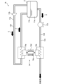
- FIG. 1 is a circuit diagram showing a reliquefaction system for hydrogen according to a first embodiment of the present invention
- FIG. FIG. 4 is a circuit diagram showing a reliquefaction system for hydrogen according to a second embodiment of the present invention
- reliquefaction systems (hereinafter simply referred to as "reliquefaction systems") 1 and 1A of first and second embodiments according to the present invention will be described with reference to the aforementioned drawings.
- reliquefaction systems the hydrogen reliquefaction systems (hereinafter simply referred to as "reliquefaction systems") 1 and 1A of first and second embodiments according to the present invention will be described with reference to the aforementioned drawings.
- the concept of direction used in the following description is used for convenience of explanation, and does not limit the orientation of the configuration of the invention to that direction.
- the reliquefaction system 1, 1A described below is merely one embodiment of the present invention. Therefore, the present invention is not limited to the embodiments, and additions, deletions, and modifications can be made without departing from the spirit of the invention.
- a reliquefaction system 1 shown in FIG. 1 is provided in a liquefied hydrogen storage facility that stores liquefied hydrogen.
- the reliquefaction system 1 comprises a liquefied hydrogen tank 11 .
- the liquefied hydrogen tank 11 stores liquefied hydrogen, that is, liquefied hydrogen.
- boil-off gas is generated due to the evaporation of part of the liquefied hydrogen.
- the reliquefaction system 1 reliquefies the boil-off gas generated in the liquefied hydrogen tank 11 .
- the reliquefaction system 1 then returns the liquefied hydrogen produced by the reliquefaction to the liquefied hydrogen tank 11 .
- the reliquefaction system 1 includes a gas delivery passage 12, a reliquefaction passage 13, and a reliquefaction device 14 in addition to the liquefied hydrogen tank 11 described above.
- the liquefied hydrogen tank 11 is a container for storing liquefied hydrogen as described above. Also, the liquefied hydrogen tank 11 includes a vacuum insulation structure. Note that the liquefied hydrogen tank 11 does not necessarily have to include a vacuum insulation structure. The inside of the liquefied hydrogen tank 11 is maintained at a hydrogen saturation temperature or lower by a vacuum insulation structure. On the other hand, in the liquefied hydrogen tank 11, boil-off gas is generated by part of the liquefied hydrogen evaporating as described above. Therefore, in the liquefied hydrogen tank 11, liquefied hydrogen is stored in the lower space 11a, and boil-off gas is stored in the upper space 11b.
- the gas delivery passage 12 is a passage through which hydrogen delivered from the liquefied hydrogen tank 11 to a supply destination flows.
- the discharged hydrogen is boil-off gas (hereinafter referred to as "discharged gas"). More specifically, one end of the gas delivery passage 12 is connected to the liquefied hydrogen tank 11 . In this embodiment, one end of the gas discharge passage 12 is connected to the upper space 11 b of the liquefied hydrogen tank 11 . On the other hand, the other end of the gas discharge passage 12 is connected to the supply destination.
- the supply destinations are hydrogen consuming equipment such as power generators and hydrogen engines, and facilities equipped with them. However, the destination of supply is not limited to hydrogen consuming equipment and facilities equipped with them.
- the gas discharge passage 12 includes a heat insulating structure 12a and a compressor 12b.
- the heat insulation structure 12 a which is an example of the first heat insulation structure, blocks heat input to the boil-off gas flowing through the gas discharge passage 12 . Then, the boil-off gas flowing through the gas delivery passage 12 is maintained at the same cryogenic temperature as the temperature inside the liquefied hydrogen tank (near the saturation temperature of hydrogen in this embodiment).
- the heat insulation structure 12a is, for example, a vacuum double tube structure.
- the compressor 12b compresses the payout gas. More specifically, the compressor 12b compresses the boil-off gas at the pressure required at the destination. Then, the compressor 12b sends the paid gas to the payee.
- a reliquefaction passage 13 carries the boil-off gas. More specifically, the reliquefaction passage 13 carries boil-off gas to be reliquefied. The reliquefaction passage 13 then returns the reliquefied liquefied hydrogen to the liquefied hydrogen tank 11 . More specifically, both ends of the reliquefaction passage 13 are connected to the liquefied hydrogen tank 11 . Specifically, both ends of the reliquefaction passage 13 are connected to the upper space 11b of the liquefied hydrogen tank 11, respectively. In addition, in this embodiment, one end of the reliquefaction passage 13 is connected to the gas discharge passage 12 . One end of the reliquefaction passage 13 is connected to the upper space 11 b of the liquefied hydrogen tank 11 via the gas discharge passage 12 .
- the reliquefaction passage 13 includes a heat insulating structure 13a and a blower 13b.
- the heat insulation structure 13 a which is an example of the second heat insulation structure, blocks heat input to the boil-off gas flowing through the reliquefaction passage 13 .
- the boil-off gas flowing through the re-liquefaction passage 13 is maintained at the same cryogenic temperature as the temperature inside the liquefied hydrogen tank (near the saturation temperature of hydrogen in this embodiment).
- the heat insulation structure 13a is, for example, a vacuum double tube structure.
- the blower 13b sucks boil-off gas from the liquefied hydrogen tank 11 .
- the blower 13b sucks part of the boil-off gas guided from the upper space 11b of the liquefied hydrogen tank 11 to the gas discharge passage 12 into the reliquefaction passage 13. Then, the blower 13b feeds downstream from the blower 13b in the reliquefaction passage 13.
- the reliquefaction device 14 cools the boil-off gas flowing through the reliquefaction passage 13 .
- the reliquefaction unit 14 then condenses the boil-off gas into liquefied hydrogen by cooling. More specifically, the reliquefaction device 14 cools the boil-off gas flowing through the reliquefaction passage 13 to a hydrogen saturation temperature or lower. As a result, at least part of the boil-off gas flowing through the reliquefaction passage 13 is condensed into liquefied hydrogen.
- a reliquefaction device 14 having such a function is a magnetic refrigerator.
- the reliquefaction device 14, which is a magnetic refrigerator will now be described in more detail.
- the reliquefaction device 14 includes a condensation section 14a and a heat radiation section 14b.
- the condensation section 14 a is provided in the reliquefaction passage 13 . More specifically, the condensing section 14a is arranged in the reliquefaction passage 13 downstream of the blower 13b. Then, the reliquefaction device 14 cools the boil-off gas via the condensation section 14a by demagnetizing.
- the heat radiating portion 14 b is provided in the gas discharge passage 12 . More specifically, the heat radiating portion 14b is arranged in the gas delivery passage 12 closer to the supply destination than the reliquefaction passage 13. As shown in FIG. Then, the reliquefying device 14 releases the heat generated when it is excited to hydrogen through the heat radiating portion 14b.
- the reliquefaction device 14 is configured, for example, as follows.
- the following example is an example of the configuration of the reliquefaction device 14 . Therefore, the reliquefaction device 14 is not limited to the following configuration. That is, the reliquefying device 14 may be configured so as to cool the boil-off gas by demagnetization as described above and release the heat during excitation to the payout gas.
- the reliquefying device 14 further includes, for example, a heat medium 14c and a magnetic field generator 14d.
- the heat medium 14c is made of a magnetic material.
- the heat medium 14c is cooled by being demagnetized and heated by being excited.
- the magnetic field generator 14d excites the heat medium 14c by generating a magnetic field around the heat medium 14c. Further, the magnetic field generator 14d demagnetizes the heat medium 14c by extinguishing the magnetic field around the heat medium 14c.
- the magnetic field generator 14d is, for example, a coil or a permanent magnet.
- the magnetic field generating section 14d When the magnetic field generating section 14d is a coil, the magnetic field generating section 14d generates or extinguishes a magnetic field around the heat medium 14c by turning on/off the current flowing through the coil. Since the heat medium 14c is cooled by extinguishing the magnetic field, the condenser 14a absorbs heat from the boil-off gas.
- the heat medium 14c Since the temperature of the heat medium 14c is increased by generating the magnetic field, the heat is released from the heat radiating portion 14b to the dispensed gas together with the previously sucked heat. As a result, heat can be transferred from the condensation portion 14a to the heat dissipation portion 14b via the heat medium 14c. Further, when the magnetic field generator 14d is a permanent magnet, the magnetic field generator 14d can generate or extinguish a magnetic field around the heat medium 14c by moving the permanent magnet toward or away from the heat medium 14c. Thereby, the heat medium 14c is cooled. Then, heat can be transported from the condensing portion 14a to the heat radiating portion 14b via the heat medium 14c.
- the heat medium 14c is thermally connected to the condensation section 14a when demagnetized. Thereby, the reliquefaction device 14 cools the boil-off gas flowing through the reliquefaction passage 13 via the condensation section 14a.
- the heat medium 14c is thermally connected to the heat radiating portion 14b when excited. As a result, the reliquefying device 14 can release heat generated during excitation to the boil-off gas in the gas discharge passage 12 from the heat radiating portion 14b. Then, the heat medium 14c can be cooled through the heat radiating portion 14b. By demagnetizing the cooled heat medium 14c again, the heat medium 14c is further cooled.
- the boil-off gas By thermally connecting the heat medium 14c to be further cooled to the condenser 14a, the boil-off gas can be cooled via the condenser 14a. Thereby, the boil-off gas is cooled by the condenser 14a. In this way, the reliquefaction device 14 can continue to cool the boil-off gas flowing through the reliquefaction passage 13 by repeating demagnetization and excitation.
- the reliquefying device 14 keeps the temperature of the condensation section 14a below the saturation temperature of hydrogen. More specifically, the condensing section 14a is cryogenic, for example, by being thermally connected to a cryogenic boil-off gas. Further, the temperature of the condensing section 14a is below the saturation temperature of hydrogen because the condensing section 14a is cooled by the demagnetization action in the reliquefying device 14 . Therefore, the temperature of the condensation section 14a is lower than the hydrogen saturation temperature corresponding to the internal pressure of the liquefied hydrogen tank 11, that is, the pressure of the boil-off gas. Thereby, the condensation part 14a can condense at least part of the boil-off gas flowing through the reliquefaction passage 13 into liquefied hydrogen. Note that the temperature of the condensation section 14a is merely an example, and is not limited to this temperature range.
- the temperature of the heat radiating section 14b is higher than the temperature of the condensing section 14a. More specifically, heat generated during excitation is radiated from the heat radiating portion 14b, so the temperature of the heat radiating portion 14b is higher than the temperature of the condensing portion 14a.
- the discharged gas from which the heat radiating portion 14b releases heat is kept at an extremely low temperature because the gas discharging passage 12 in which the heat radiating portion 14b is provided includes the heat insulating structure 12a.
- the heat radiation part 14b has a cryogenic temperature of 20K or more and 70K or less in this embodiment.
- the temperature difference between the heat radiating portion 14b and the condensing portion 14a can be 50K or less.
- the temperature of the condensation portion 14a can be lowered to less than the saturation temperature when the condensation portion 14a is cooled by demagnetization after releasing the heat of the heat radiation portion 14b to the discharge gas. That is, the temperature difference between the heat radiating portion 14b and the condensing portion 14a can be kept within the operating range of the magnetic refrigerator.
- the reliquefaction device 14 cools the condensation part 14a by demagnetization. Then, the reliquefying device 14 releases the heat generated during the excitation to the dispensed gas through the heat radiating portion 14b. As a result, the temperature of the condensation section 14a is maintained at the hydrogen saturation temperature, which is 30K or lower in the present embodiment. At least a portion of the boil-off gas passing through the recondenser 14 is then condensed into liquefied hydrogen. Also, the condensed liquefied hydrogen is returned to the liquefied hydrogen tank 11 through the reliquefaction passage 13 together with the remaining boil-off gas. In this manner, the reliquefaction system 1 reliquefies the boil-off gas generated in the liquefied hydrogen tank 11 and returns it to the liquefied hydrogen tank 11 (see arrow C in FIG. 1).
- the reliquefaction system 1 of this embodiment includes a condensation section 14 a provided in the reliquefaction passage 13 and a heat radiation section 14 b provided in the gas discharge passage 12 . Therefore, a magnetic refrigerator having a narrow operating temperature range can be applied to the reliquefying device 14 by dissipating heat to the gas discharge passage 12 whose temperature is much lower than that of the atmosphere.
- the magnetic refrigerator can cool the boil-off gas and radiate heat to the discharge gas by switching between demagnetization and excitation.
- equipment such as a compressor included in the gas refrigerator can be eliminated.
- the reliquefaction device 14 can perform reliquefaction with higher efficiency than a gas refrigeration type reliquefaction device.
- equipment such as a compressor can be eliminated, the size of the reliquefying device 14 can be reduced.
- the heat radiating section 14b dissipates heat from the dispensed gas dispensed from the liquefied hydrogen tank 11 in the same manner as the boil-off gas to be reliquefied. Therefore, the temperature difference between the condensing portion 14a and the heat radiating portion 14b can be reduced. As a result, it is possible to prevent the configuration of the reliquefying device 14 from becoming complicated. More specifically, when the temperature difference between the condensation section 14a and the heat radiation section 14b is large, it is necessary to provide a large number of refrigerators between the condensation section 14a and the heat radiation section 14b. become.
- the reliquefying device 14 can be configured with, for example, one magnetic refrigerator. Therefore, complication of the configuration of the reliquefaction device 14 can be further suppressed. However, it cannot be denied that the reliquefaction unit 14 includes a plurality of magnetic refrigerators.
- the reliquefaction passage 13 is formed so as to branch off from the gas delivery passage 12 .
- the heat radiating portion 14 b is arranged on the supply destination side (that is, downstream) from the portion where the reliquefaction passage 13 connects with the gas delivery passage 12 . Therefore, the boil-off gas to be re-liquefied can be guided to the re-liquefaction passage 13 without passing through the heat radiation portion 14b. Therefore, the re-liquefied boil-off gas does not absorb the heat emitted from the heat radiating portion 14b.
- the boil-off gas at a lower temperature can flow through the reliquefaction passage 13 compared to the case where the heat radiating portion 14b is arranged on the upstream side of the reliquefaction passage 13 . Therefore, the temperature of the boil-off gas flowing through the reliquefaction passage 13 can be kept low. As a result, the temperature to be lowered during reliquefaction can be reduced.
- the gas discharge passage 12 and the reliquefaction passage 13 have the heat insulating structures 12a and 13a, respectively, so that the hydrogen and the boil-off gas are kept at extremely low temperatures and guided to the heat radiating portion 14b and the condensing portion 14a. be able to.
- the boil-off gas can be re-liquefied by setting the temperature of the condensation section 14a below the saturation temperature of hydrogen. Further, by making the heat radiating portion 14b higher than the condensing portion 14a and keeping the temperature difference between the heat radiating portion 14b and the condensing portion 14a at 40K or less, the temperature difference can be kept within the operating range of the magnetic refrigerator. As a result, it is possible to prevent the configuration of the reliquefying device 14 from becoming complicated.
- the reliquefaction system 1A of the second embodiment is similar in configuration to the reliquefaction system 1 of the first embodiment. Therefore, with regard to the configuration of the reliquefaction system 1A of the second embodiment, mainly the points that differ from the reliquefaction system 1 of the first embodiment will be described, and the same configurations will be assigned the same reference numerals, and description thereof will be omitted. be.
- a reliquefaction system 1A of the second embodiment includes a liquefied hydrogen tank 11, a liquid discharge passage 12A, a reliquefaction passage 13, and a reliquefaction device 14.
- the liquid dispensing passage 12A is a passage through which hydrogen dispensed from the liquefied hydrogen tank 11 flows.
- the discharged hydrogen is liquefied hydrogen (hereinafter referred to as "discharge liquid").
- one end of the liquid discharge passage 12A is connected to the liquefied hydrogen tank 11.
- one end of the liquid dispensing passage 12A is connected to the lower space 11a of the liquefied hydrogen tank 11 .
- the other end of the liquid dispensing passage 12A is connected to the supply destination.
- the liquid dispensing passage 12A includes a heat insulating structure 12a and a pump 12c. The pump 12c sends out the dispensed liquid guided from the liquefied hydrogen tank 11 to the supply destination side in the liquid dispensation passage 12A.
- the liquid discharge passage 12A has a heat exchanger (not shown).
- the liquid dispensing passage 12A vaporizes the dispensing liquid by applying heat to the dispensing liquid with a heat exchanger. Then, the facility equipped with the reliquefaction system 1A supplies the vaporized hydrogen gas to the supply destination (see arrow D in FIG. 2).
- both ends of the reliquefaction passage 13A are connected to the liquefied hydrogen tank 11. Specifically, both ends of the reliquefaction passage 13 are connected to the upper space 11b of the liquefied hydrogen tank 11, respectively.
- the reliquefaction passage 13A is directly connected to the upper space 11b of the liquefied hydrogen tank 11, but the gas is liquefied through the unillustrated gas discharge passage 12, similar to the reliquefaction passage 13 of the first embodiment. It may be connected to the hydrogen tank 11 .
- the reliquefaction passage 13A also includes a blower 13b.
- the condensation section 14a is provided in the reliquefaction passage 13A, and the heat radiation section 14b is provided in the liquid discharge passage 12A.
- the heat radiating portion 14b is arranged on the supply destination side of the pump 12c in the liquid dispensing passage 12A. More specifically, the heat radiating portion 14b is arranged upstream of a heat exchanger (not shown) in the liquid dispensing passage 12A.
- the re-liquefaction system 1A when the pump 12c of the liquid dispensing passage 12A operates, the dispensing liquid is dispensed from the liquefied hydrogen tank 11 to the liquid dispensing passage 12A (see arrow D in FIG. 2). Also, in the reliquefaction passage 13A, the boil-off gas is sent to the reliquefaction device 14 by the blower 13b (see arrow E in FIG. 2). In the reliquefying device 14, the condensing portion 14a is cooled by demagnetization, and the heat generated during the excitation is released to the dispensed liquid via the heat radiating portion 14b.
- the heat radiating section 14b radiates heat to the liquefied hydrogen at a lower temperature than the boil-off gas. Therefore, it is possible to reduce the temperature difference between the condenser portion 14a and the heat radiation portion 14b, thereby suppressing the complication of the configuration of the magnetic refrigerator.
- the reliquefaction system 1A of the second embodiment has the same effects as the reliquefaction system 1 of the first embodiment.
- the reliquefaction systems 1 and 1A of the first and second embodiments are provided in liquefied hydrogen storage facilities, but the reliquefaction systems 1 and 1A are not necessarily limited to liquefied hydrogen storage facilities.
- the reliquefaction system 1, 1A may be provided in a vehicle such as a ship or vehicle, or may be provided in other equipment.
- the heat radiating section 14b is arranged on the supply destination side of the reliquefaction passage 13 in the gas delivery passage 12 .
- the heat radiating portion 14b may be arranged on the liquefied hydrogen tank 11 side of the reliquefaction passage 13 in the gas discharge passage 12 .
- the heat radiating section 14b is arranged downstream of the pump 12c and upstream of the heat exchanger (not shown) in the liquid discharge passage 12A.
- the radiator 14b may be arranged upstream of the pump 12c.
- the reliquefaction device 14 which is a magnetic refrigerator, does not necessarily have to be configured as described above.
- the reliquefying device 14 is demagnetized to cool the boil-off gas via the condensation section 14a and release the heat generated during excitation to the dispensed gas or the dispensed liquid via the heat radiation section 14b.
Landscapes
- Engineering & Computer Science (AREA)
- Mechanical Engineering (AREA)
- General Engineering & Computer Science (AREA)
- Physics & Mathematics (AREA)
- Thermal Sciences (AREA)
- Filling Or Discharging Of Gas Storage Vessels (AREA)
Abstract
Description
<再液化システム>
図1に示す再液化システム1は、液化水素を貯蔵する液化水素貯蔵設備に備わっている。再液化システム1は、液化水素タンク11を備えている。液化水素タンク11は、液化した水素、即ち液化水素を貯蔵している。また、液化水素タンク11では、液化水素の一部が蒸発することによってボイルオフガスが発生している。再液化システム1は、液化水素タンク11内で発生するボイルオフガスを再液化する。そして、再液化システム1は、再液化によって生成された液化水素を液化水素タンク11に戻す。更に詳細に説明すると、再液化システム1は、前述する液化水素タンク11に加えて、ガス払出通路12と、再液化通路13と、再液化装置14と、を備えている。
液化水素タンク11は、前述の通り液化水素を貯蔵する容器である。また、液化水素タンク11は、真空断熱構造を含んでいる。なお、液化水素タンク11は、必ずしも真空断熱構造を含む必要はない。そして、液化水素タンク11内は、真空断熱構造によって水素の飽和温度以下に維持されている。他方、液化水素タンク11内では、前述の通り液化水素の一部が蒸発することによってボイルオフガスが発生している。それ故、液化水素タンク11内では、下側空間11aに液化水素が貯留され、上側空間11bにボイルオフガスが溜まっている。
ガス払出通路12は、液化水素タンク11から供給先に払出す水素が流れる通路である。本実施形態において、払出される水素は、ボイルオフガス(以下、「払出ガス」という)である。更に詳細に説明すると、ガス払出通路12の一端は、液化水素タンク11に繋がっている。本実施形態において、ガス払出通路12の一端は、液化水素タンク11の上側空間11bに繋がっている。他方、ガス払出通路12の他端は、供給先に繋がっている。そして供給先は、発電機器及び水素エンジン等の水素消費機器、並びにそれらを備える設備である。但し、供給先は、水素消費機器、並びにそれらを備える設備に限定されない。
再液化通路13は、ボイルオフガスを流す。更に詳細に説明すると、再液化通路13は、再液化するボイルオフガスを流す。そして、再液化通路13は、再液化した液化水素を液化水素タンク11に戻す。より詳細に説明すると、再液化通路13の両端は、液化水素タンク11に繋がっている。具体的に説明すると、再液化通路13の両端は、共に液化水素タンク11の上側空間11bに夫々繋がっている。なお、本実施形態において、再液化通路13の一端は、ガス払出通路12に接続されている。そして、再液化通路13の一端は、ガス払出通路12を介して液化水素タンク11の上側空間11bに接続されている。
再液化装置14は、再液化通路13を流れるボイルオフガスを冷却する。そして、再液化装置14は、冷却することによってボイルオフガスを液化水素に凝縮する。より詳細には、再液化装置14は、再液化通路13を流れるボイルオフガスを水素の飽和温度以下まで冷却する。これにより、再液化通路13を流れるボイルオフガスの少なくとも一部が液化水素に凝縮される。このような機能を有する再液化装置14は、磁気冷凍機である。以下、磁気冷凍機である再液化装置14について更に詳細に説明する。
再液化システム1では、ガス払出通路12の圧縮機12bが作動すると、液化水素タンク11から供給先に払出ガスが払出される(図1の矢付A参照)。また、再液化システム1では、再液化通路13のブロア13bも作動している。これにより、液化水素タンク11のボイルオフガスが再液化通路13にも流れる。より詳細に説明すると、ガス払出通路12を流れるボイルオフガスの一部がブロア13bによって再液化通路13に吸入される。更に、ブロア13bは、吸入したボイルオフガスを下流側にある再液化装置14に送る(図1の矢付B参照)。
第2実施形態の再液化システム1Aは、第1実施形態の再液化システム1と構成が類似している。従って、第2実施形態の再液化システム1Aの構成については、主に第1実施形態の再液化システム1と異なる点が説明され、同一の構成については同一の符号を付して説明が省略される。
第1及び第2実施形態の再液化システム1,1Aは、液化水素貯蔵設備に設けられているが、再液化システム1、1Aが設けられるものは必ずしも液化水素貯蔵設備に限定されない。例えば、再液化システム1、1Aは、船舶や車両などの乗り物に備わっていてもよく、その他の機器に備わっていてもよい。
Claims (5)
- 液化水素タンク内で発生したボイルオフガスを再液化して前記液化水素タンクに戻す水素用再液化システムであって、
前記液化水素タンクから供給先に払出す水素が流れる払出通路と、
ボイルオフガスが流れる再液化通路と、
前記再液化通路を流れるボイルオフガスを冷却することによってボイルオフガスを凝縮する再液化装置と、を備え、
前記再液化装置は、前記再液化通路に設けられる凝縮部と、前記払出通路に設けられる放熱部とを含み、消磁することによって前記凝縮部を介してボイルオフガスを冷却し且つ励磁する際の熱を前記放熱部を介して水素に放出する磁気冷凍機である、水素用再液化システム。 - 前記払出通路は、前記液化水素タンクから前記供給先に払出される水素であるボイルオフガスが流れ、
前記磁気冷凍機は、前記放熱部を介して前記払出通路を流れるボイルオフガスに放熱する、請求項1に記載の水素用再液化システム。 - 前記払出通路は、前記液化水素タンクに接続され、
前記再液化通路は、前記払出通路を介して前記液化水素タンクに接続され
前記再液化装置の前記放熱部は、前記払出通路において前記再液化通路より前記供給先側に配置されている、請求項2に記載の水素用再液化システム。 - 前記払出通路は、前記液化水素タンクから前記供給先に払出される水素である液化水素が流れ、
前記再液化装置は、前記放熱部を介して前記払出通路を流れる液化水素に放熱する、請求項1に記載の水素用再液化システム。 - 前記払出通路は、水素への入熱を遮断する第1断熱構造を有し、
前記再液化通路は、ボイルオフガスへの入熱を遮断する第2断熱構造を有し、
前記再液化装置は、前記凝縮部の温度を水素の飽和温度未満であって30K以下とし、前記放熱部の温度を20K以上であって前記凝縮部より高くし、前記放熱部と前記凝縮部との温度差を50K以下とする、請求項1乃至4の何れか1つに記載の水素用再液化システム。
Priority Applications (4)
| Application Number | Priority Date | Filing Date | Title |
|---|---|---|---|
| CN202280076815.0A CN118265870A (zh) | 2021-11-24 | 2022-11-08 | 氢用再液化系统 |
| KR1020247015306A KR20240068796A (ko) | 2021-11-24 | 2022-11-08 | 수소용 재액화 시스템 |
| US18/711,907 US20240337439A1 (en) | 2021-11-24 | 2022-11-08 | Hydrogen re-liquefaction system |
| EP22898388.8A EP4438940A4 (en) | 2021-11-24 | 2022-11-08 | HYDROGEN RE-LIQUEFACTION SYSTEM |
Applications Claiming Priority (2)
| Application Number | Priority Date | Filing Date | Title |
|---|---|---|---|
| JP2021-190263 | 2021-11-24 | ||
| JP2021190263A JP7788839B2 (ja) | 2021-11-24 | 2021-11-24 | 水素用再液化システム |
Publications (1)
| Publication Number | Publication Date |
|---|---|
| WO2023095604A1 true WO2023095604A1 (ja) | 2023-06-01 |
Family
ID=86539446
Family Applications (1)
| Application Number | Title | Priority Date | Filing Date |
|---|---|---|---|
| PCT/JP2022/041542 Ceased WO2023095604A1 (ja) | 2021-11-24 | 2022-11-08 | 水素用再液化システム |
Country Status (6)
| Country | Link |
|---|---|
| US (1) | US20240337439A1 (ja) |
| EP (1) | EP4438940A4 (ja) |
| JP (1) | JP7788839B2 (ja) |
| KR (1) | KR20240068796A (ja) |
| CN (1) | CN118265870A (ja) |
| WO (1) | WO2023095604A1 (ja) |
Cited By (2)
| Publication number | Priority date | Publication date | Assignee | Title |
|---|---|---|---|---|
| EP4517154A1 (en) | 2023-08-30 | 2025-03-05 | Air Products and Chemicals, Inc. | Apparatus and process for cryogenic liquid vaporization to recool gas for cryogenic fluid recovery |
| EP4556780A1 (en) | 2023-11-20 | 2025-05-21 | Air Products and Chemicals, Inc. | Apparatus and process for cooling pressurized gas for fueling |
Families Citing this family (1)
| Publication number | Priority date | Publication date | Assignee | Title |
|---|---|---|---|---|
| US12429157B2 (en) * | 2023-03-17 | 2025-09-30 | H2CREO Corp. | Two-way twin-axial connector module of a receptacle for transporting liquefied gas and liquefied gas transport system including the same |
Citations (4)
| Publication number | Priority date | Publication date | Assignee | Title |
|---|---|---|---|---|
| JPH04370499A (ja) * | 1991-06-18 | 1992-12-22 | Tokyo Gas Co Ltd | 液化天然ガス貯蔵タンク内に発生した蒸発ガスの処理方法 |
| JP2005273681A (ja) | 2004-03-22 | 2005-10-06 | Ebara Corp | 低温液化ガス貯留システム |
| JP2006200553A (ja) * | 2005-01-18 | 2006-08-03 | Iwatani Internatl Corp | 液化ガス流量計測システム |
| JP2018091391A (ja) * | 2016-12-01 | 2018-06-14 | 株式会社前川製作所 | ボイルオフガスの液化システム |
Family Cites Families (3)
| Publication number | Priority date | Publication date | Assignee | Title |
|---|---|---|---|---|
| FR2663714B1 (fr) * | 1990-06-20 | 1992-09-11 | Air Liquide | Procede et installation de transfert d'hydrogene liquide. |
| US6336331B1 (en) * | 2000-08-01 | 2002-01-08 | Praxair Technology, Inc. | System for operating cryogenic liquid tankage |
| FR3015306A1 (fr) * | 2013-12-20 | 2015-06-26 | Air Liquide | Procede et appareil de separation a temperature subambiante |
-
2021
- 2021-11-24 JP JP2021190263A patent/JP7788839B2/ja active Active
-
2022
- 2022-11-08 EP EP22898388.8A patent/EP4438940A4/en active Pending
- 2022-11-08 US US18/711,907 patent/US20240337439A1/en active Pending
- 2022-11-08 CN CN202280076815.0A patent/CN118265870A/zh active Pending
- 2022-11-08 KR KR1020247015306A patent/KR20240068796A/ko active Pending
- 2022-11-08 WO PCT/JP2022/041542 patent/WO2023095604A1/ja not_active Ceased
Patent Citations (4)
| Publication number | Priority date | Publication date | Assignee | Title |
|---|---|---|---|---|
| JPH04370499A (ja) * | 1991-06-18 | 1992-12-22 | Tokyo Gas Co Ltd | 液化天然ガス貯蔵タンク内に発生した蒸発ガスの処理方法 |
| JP2005273681A (ja) | 2004-03-22 | 2005-10-06 | Ebara Corp | 低温液化ガス貯留システム |
| JP2006200553A (ja) * | 2005-01-18 | 2006-08-03 | Iwatani Internatl Corp | 液化ガス流量計測システム |
| JP2018091391A (ja) * | 2016-12-01 | 2018-06-14 | 株式会社前川製作所 | ボイルオフガスの液化システム |
Non-Patent Citations (1)
| Title |
|---|
| See also references of EP4438940A4 |
Cited By (3)
| Publication number | Priority date | Publication date | Assignee | Title |
|---|---|---|---|---|
| EP4517154A1 (en) | 2023-08-30 | 2025-03-05 | Air Products and Chemicals, Inc. | Apparatus and process for cryogenic liquid vaporization to recool gas for cryogenic fluid recovery |
| EP4556780A1 (en) | 2023-11-20 | 2025-05-21 | Air Products and Chemicals, Inc. | Apparatus and process for cooling pressurized gas for fueling |
| US12497936B2 (en) | 2023-11-20 | 2025-12-16 | Air Products And Chemicals, Inc. | Apparatus and process for cooling pressurized gas for fueling |
Also Published As
| Publication number | Publication date |
|---|---|
| JP7788839B2 (ja) | 2025-12-19 |
| US20240337439A1 (en) | 2024-10-10 |
| KR20240068796A (ko) | 2024-05-17 |
| EP4438940A1 (en) | 2024-10-02 |
| EP4438940A4 (en) | 2025-12-10 |
| JP2023077109A (ja) | 2023-06-05 |
| CN118265870A (zh) | 2024-06-28 |
Similar Documents
| Publication | Publication Date | Title |
|---|---|---|
| WO2023095604A1 (ja) | 水素用再液化システム | |
| JP4873210B2 (ja) | 低温燃料用貯蔵容器 | |
| JP6769850B2 (ja) | ボイルオフガスの液化システム | |
| KR101310025B1 (ko) | 저장 액체의 재액화 방법 | |
| CN103857955A (zh) | 储槽的压力上升抑制装置、具有该装置的压力上升抑制系统、其抑制方法、具有该装置的液化气体运输船及具有该装置的液化气体储藏设备 | |
| CN101796343A (zh) | 液化气再液化装置、具有该装置的液化气贮藏设备及液化气运输船、以及液化气再液化方法 | |
| JPH11288809A (ja) | 超電導マグネット装置 | |
| JP2005351613A (ja) | 冷却装置 | |
| CN103538722B (zh) | 冷却单元的功率电子器件的热耗散 | |
| CN103091653B (zh) | 用于在第一模式和第二模式之间交替切换持续电流开关的系统和方法 | |
| KR101167148B1 (ko) | 증발가스 재액화 장치 | |
| US20200333058A1 (en) | Refrigeration device | |
| JP2023077109A5 (ja) | ||
| KR100747232B1 (ko) | 증발가스 재액화 장치 및 방법과 이 장치가 장착된 lng운반선 | |
| JP2018127137A (ja) | 液化ガス運搬用液化ガス燃料船 | |
| JP2009191945A (ja) | 液化ガス貯蔵設備とその運転方法 | |
| JP2005221223A (ja) | 気体再液化方法 | |
| JP2019117026A (ja) | 超電導ケーブルの冷却装置及び初期冷却方法 | |
| JPH11248326A (ja) | 冷凍機 | |
| JP6922769B2 (ja) | 低温液化ガス貯留タンクのbog抑制方法及び装置 | |
| JP2010101580A (ja) | 極低温冷媒再凝縮装置および超電導磁石装置 | |
| JP2001091173A (ja) | 熱搬送装置 | |
| JP3529437B2 (ja) | 超電導磁石装置 | |
| KR20070006590A (ko) | 과냉각된 수평 저온유지장치 | |
| JP2024143489A (ja) | 磁気冷凍システム及び設備 |
Legal Events
| Date | Code | Title | Description |
|---|---|---|---|
| 121 | Ep: the epo has been informed by wipo that ep was designated in this application |
Ref document number: 22898388 Country of ref document: EP Kind code of ref document: A1 |
|
| ENP | Entry into the national phase |
Ref document number: 20247015306 Country of ref document: KR Kind code of ref document: A |
|
| WWE | Wipo information: entry into national phase |
Ref document number: 202280076815.0 Country of ref document: CN |
|
| WWE | Wipo information: entry into national phase |
Ref document number: 2022898388 Country of ref document: EP |
|
| NENP | Non-entry into the national phase |
Ref country code: DE |
|
| ENP | Entry into the national phase |
Ref document number: 2022898388 Country of ref document: EP Effective date: 20240624 |