WO2023095426A1 - リール装置 - Google Patents
リール装置 Download PDFInfo
- Publication number
- WO2023095426A1 WO2023095426A1 PCT/JP2022/034662 JP2022034662W WO2023095426A1 WO 2023095426 A1 WO2023095426 A1 WO 2023095426A1 JP 2022034662 W JP2022034662 W JP 2022034662W WO 2023095426 A1 WO2023095426 A1 WO 2023095426A1
- Authority
- WO
- WIPO (PCT)
- Prior art keywords
- reel device
- clutch
- rotor
- spool
- outer rotor
- Prior art date
- Legal status (The legal status is an assumption and is not a legal conclusion. Google has not performed a legal analysis and makes no representation as to the accuracy of the status listed.)
- Ceased
Links
Images










Classifications
-
- A—HUMAN NECESSITIES
- A01—AGRICULTURE; FORESTRY; ANIMAL HUSBANDRY; HUNTING; TRAPPING; FISHING
- A01K—ANIMAL HUSBANDRY; AVICULTURE; APICULTURE; PISCICULTURE; FISHING; REARING OR BREEDING ANIMALS, NOT OTHERWISE PROVIDED FOR; NEW BREEDS OF ANIMALS
- A01K89/00—Reels
- A01K89/015—Reels with a rotary drum, i.e. with a rotating spool
- A01K89/0155—Antibacklash devices
- A01K89/01555—Antibacklash devices using magnets
-
- A—HUMAN NECESSITIES
- A01—AGRICULTURE; FORESTRY; ANIMAL HUSBANDRY; HUNTING; TRAPPING; FISHING
- A01K—ANIMAL HUSBANDRY; AVICULTURE; APICULTURE; PISCICULTURE; FISHING; REARING OR BREEDING ANIMALS, NOT OTHERWISE PROVIDED FOR; NEW BREEDS OF ANIMALS
- A01K89/00—Reels
- A01K89/015—Reels with a rotary drum, i.e. with a rotating spool
- A01K89/0183—Drive mechanism details
- A01K89/0184—Multiple drive ratio
-
- A—HUMAN NECESSITIES
- A01—AGRICULTURE; FORESTRY; ANIMAL HUSBANDRY; HUNTING; TRAPPING; FISHING
- A01K—ANIMAL HUSBANDRY; AVICULTURE; APICULTURE; PISCICULTURE; FISHING; REARING OR BREEDING ANIMALS, NOT OTHERWISE PROVIDED FOR; NEW BREEDS OF ANIMALS
- A01K89/00—Reels
- A01K89/015—Reels with a rotary drum, i.e. with a rotating spool
- A01K89/0183—Drive mechanism details
- A01K89/0186—Drive mechanism details with disengageable positive drive components, e.g. a clutch
- A01K89/0188—Axially engaged
- A01K89/0189—Coaxial of spool
-
- A—HUMAN NECESSITIES
- A01—AGRICULTURE; FORESTRY; ANIMAL HUSBANDRY; HUNTING; TRAPPING; FISHING
- A01K—ANIMAL HUSBANDRY; AVICULTURE; APICULTURE; PISCICULTURE; FISHING; REARING OR BREEDING ANIMALS, NOT OTHERWISE PROVIDED FOR; NEW BREEDS OF ANIMALS
- A01K89/00—Reels
- A01K89/015—Reels with a rotary drum, i.e. with a rotating spool
- A01K89/0183—Drive mechanism details
- A01K89/01903—Drive mechanism details with yieldable drive coupling, e.g. friction or fluid clutch
- A01K89/01908—Coaxial with spool
-
- A—HUMAN NECESSITIES
- A01—AGRICULTURE; FORESTRY; ANIMAL HUSBANDRY; HUNTING; TRAPPING; FISHING
- A01K—ANIMAL HUSBANDRY; AVICULTURE; APICULTURE; PISCICULTURE; FISHING; REARING OR BREEDING ANIMALS, NOT OTHERWISE PROVIDED FOR; NEW BREEDS OF ANIMALS
- A01K89/00—Reels
- A01K89/015—Reels with a rotary drum, i.e. with a rotating spool
- A01K89/0183—Drive mechanism details
- A01K89/01912—Drive mechanism details with level winding
- A01K89/019125—Line shifts along a rotatable cam bar
-
- H—ELECTRICITY
- H02—GENERATION; CONVERSION OR DISTRIBUTION OF ELECTRIC POWER
- H02K—DYNAMO-ELECTRIC MACHINES
- H02K49/00—Dynamo-electric clutches; Dynamo-electric brakes
- H02K49/10—Dynamo-electric clutches; Dynamo-electric brakes of the permanent-magnet type
- H02K49/102—Magnetic gearings, i.e. assembly of gears, linear or rotary, by which motion is magnetically transferred without physical contact
Definitions
- the present invention relates to a reel device.
- the present invention has been made in view of the above circumstances, and an object of the present invention is to suitably transmit rotational torque.
- the present invention is a reel device, a rotation input unit to which a rotation force is input; a thread winding portion that is rotatably supported and around which the string-like body is wound; a speed change mechanism capable of changing the speed of the rotational force input to the rotational input portion by magnetic modulation and transmitting it to the thread winding portion; Prepare.
- FIG. 2 is a cross-sectional view of the speed change mechanism taken along line II-II of FIG. 1;
- FIG. FIG. 4 is a schematic side view showing the clutch in a connected state; It is a figure which shows the opposing state of the magnet in a clutch in a connection state.
- FIG. 5 is a schematic side view showing the clutch in a disconnected state;
- FIG. 10 is a diagram showing how magnets face each other in a clutch in a disengaged state; It is a figure for demonstrating operation
- FIG. 5 is a diagram showing an example of slip torque (out-of-step torque) waveforms of an outer rotor, an inner rotor, and a stator when the stator is forcibly rotated;
- FIG. 5 is a diagram comparing torque peak values when the stator is forcibly rotated; It is a sectional view showing typically the reel device concerning the 2nd modification of an embodiment. It is a figure for demonstrating operation
- FIG. 1 is a cross-sectional view schematically showing a reel device 1 according to this embodiment.
- the reel device 1 according to this embodiment is a bait reel for fishing.
- the reel device 1 includes a handle 2 to which a user inputs a rotational force, a speed change mechanism 3 capable of changing and outputting the rotational force input to the handle 2, and torque from the speed change mechanism 3 to the spool 6. It has a clutch 5 for switching the transmission state, and a spool 6 around which a fishing line L (see FIG. 5A etc.) is wound.
- the handle 2 , transmission mechanism 3 , clutch 5 and spool 6 are supported by a frame (body) 10 .
- the handle 2 has a grip 21 to be gripped by the user, and an arm 22 having one end provided with the grip 21 and the other end connected to the transmission mechanism 3 .
- the arm 22 is rotatably supported by the frame 10 via a one-way clutch 23 around the central axis Ax.
- the one-way clutch 23 rotates the handle 2 only in one direction corresponding to the direction in which the fishing line L is wound by the spool 6. - ⁇
- the direction along the central axis Ax is called the "axial direction”
- the direction perpendicular to the central axis Ax is called the "radial direction”
- the direction of rotation about the central axis Ax is called the "circumferential direction”.
- the side on which the handle 2 is arranged is called the "input side”
- the opposite side the left side in FIG. 1 is called the "counter-input side”.
- the spool 6 is formed in a substantially cylindrical shape along the axial direction, and a fishing line L is wound around its outer peripheral surface.
- the spool 6 is rotatably supported by the frame 10 about the central axis Ax via an integrally constructed spool shaft 61, and the fishing line L is wound and paid out by its rotation.
- a brake 7 is provided on the opposite side of the spool 6 from the clutch 5 in the axial direction.
- the brake 7 is connected to the spool shaft 61 and applies braking force to the spool 6 via the spool shaft 61 .
- the brake 7 applies a braking force to the spool 6 according to its rotational speed to suppress backlash and stabilize casting.
- conventionally known techniques such as a centrifugal brake and a magnetic brake can be applied.
- FIG. 2 is a diagram for explaining the structure of the speed change mechanism 3, and is a cross-sectional view of the speed change mechanism 3 taken along line II-II of FIG.
- the speed change mechanism 3 is disposed between the handle 2 and the spool 6, and can change the speed of the rotational force input to the handle 2 by magnetic modulation and transmit it to the spool 6.
- the transmission mechanism 3 is a magnetic modulation gear and includes an outer rotor (input shaft) 31 , an inner rotor (output shaft) 32 and a stator 33 .
- the outer rotor 31 is formed in a substantially cylindrical shape centered on the central axis Ax, and has an outer pole magnet 31a.
- the outer pole magnets 31a are permanent magnets such as neodymium magnets, and a plurality of magnets with different polarities are alternately arranged in the circumferential direction.
- the arm 22 of the handle 2 is connected to the end of the outer rotor 31 on the input side in the axial direction, and rotational force is input from the handle 2 .
- the outer rotor 31 may have a yoke or the like that supports the outer pole magnets 31a.
- the outer pole magnet 31a may be in the shape of an integral ring, or may be in the shape of a plurality of divided magnets arranged in the circumferential direction.
- the inner rotor 32 is arranged concentrically on the inner diameter side of the outer rotor 31 and has a shaft 32a and an inner pole magnet 32b.
- a spool 6 (spool shaft 61 ) is connected via a clutch 5 to the non-input side of the inner rotor 32 .
- the shaft 32a is rotatably supported around the central axis Ax.
- the inner pole magnets 32b are permanent magnets such as neodymium magnets, for example, and have a smaller number of poles than the outer pole magnets 31a of the outer rotor 31.
- a plurality of magnets with different polarities are arranged alternately in the circumferential direction. , is attached to the outer peripheral surface of the shaft 32a.
- the inner pole magnet 32b may have an integral ring shape, or may have a shape in which divided magnets are arranged in the circumferential direction.
- the inner rotor 32 is configured so that the inner pole magnet 32b can move in the axial direction, and the position in the axial direction can be adjusted by the drag screw 34.
- the drag screw 34 is arranged outside the frame 10 and connected to the input side of the inner rotor 32 .
- the drag screw 34 is supported by the frame 10 by, for example, a ball screw, and is configured to move the inner pole magnet 32b in the axial direction as it rotates.
- the inner rotor 32 may be configured such that the inner pole magnet 32b is movable in the axial direction, and the inner pole magnet 32b alone may be moved without moving the shaft 32a. It may be configured to move.
- the stator 33 is formed in a substantially cylindrical shape and arranged radially between the outer rotor 31 and the inner rotor 32 and concentrically therewith. Both axial ends of the stator 33 are fixed to the frame (body) 10 .
- the stator 33 has a magnetic pole piece (pole piece) 33a arranged on the outer diameter side of the inner pole magnet 32b.
- the magnetic pole pieces 33a are composed of laminated steel plates, and a plurality of pieces are arranged at predetermined intervals in the circumferential direction.
- the number of magnetic pole pieces 33a is the number of outer pole pairs (the number of pole pairs of the outer magnet 31a) ⁇ the number of inner pole pairs (the number of pole pairs of the inner pole magnet 32b), and is generally the number of outer pole pairs + the number of inner pole pairs.
- Two magnetic pole pieces 33a adjacent in the circumferential direction may be connected by a thin connecting portion, may be connected by a non-magnetic material, or may not be connected. Note that FIG. 2 illustrates an example in which two adjacent magnetic pole pieces 33a are connected at an intermediate position in the radial direction. Further, the magnetic pole piece 33a may not be composed of laminated steel plates as long as it is a magnetic material. good.
- the transmission mechanism 3 having the above configuration, when rotation is input to the outer rotor 31 , the spatial magnetic flux waveform of the outer pole magnets 31 a of the outer rotor 31 is changed by the magnetic pole pieces 33 a of the stator 33 to the inner pole magnets of the inner rotor 32 . 32b, and torque is transmitted to the inner rotor 32 using the magnetic force between the pole piece 33a and the inner pole magnet 32b. That is, in the transmission mechanism 3, power is transmitted from the outer rotor 31 to the inner rotor 32 by the modulated magnetic flux. At this time, the gear ratio is the number of outer pole pairs/the number of inner pole pairs (the rotation is in the opposite direction).
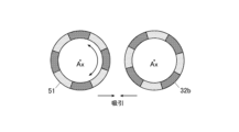
- FIG. 3A is a schematic side view showing the clutch 5 in the connected state
- FIG. 3B is a diagram showing how magnets face each other in the clutch 5 in the connected state
- FIG. 4A is a schematic side view showing the clutch 5 in the disconnected state
- FIG. 4B is a diagram showing how magnets face each other in the clutch 5 in the disconnected state.
- the clutch 5 is arranged between the speed change mechanism 3 and the spool 6, and can switch the torque transmission state between the speed change mechanism 3 and the spool 6 between a state in which torque is transmitted and a state in which torque is not transmitted. . That is, the clutch 5 switches the transmission mechanism 3 and the spool 6 between a connected state in which they are connected and a disconnected state in which the connection is released.
- the clutch 5 includes a clutch magnet 51 and a key member 52 .
- the clutch magnet 51 is formed in a disc shape centered on the central axis Ax, and is provided at the input-side end of the spool shaft 61 .
- the clutch magnet 51 is configured to have the same inner/outer diameter size and polarity arrangement as those of the inner pole magnet 32b, and is arranged so as to axially face the end face of the inner pole magnet 32b on the counter-input side. That is, the clutch magnet 51 has the same number of poles as the inner pole magnet 32b, and a plurality of magnets with different polarities are alternately arranged in the circumferential direction.
- the clutch magnet 51 is rotatably supported around the central axis Ax and connected to a clutch lever 53 attached to the frame 10 .
- the clutch magnet 51 When the clutch lever 53 is operated, the clutch magnet 51 rotates about the central axis Ax by one pole so that the polarity position of the clutch magnet 51 in the circumferential direction is reversed. As for the rotation of the clutch magnet 51 by the clutch lever 53, the clutch magnet 51 may rotate integrally with the spool shaft 61, or only the clutch magnet 51 may rotate.
- the key member 52 is provided at the input-side end of the spool shaft 61 and is fitted into a key groove 54 provided at the non-input-side end of the inner rotor 32 to provide a gap between the inner rotor 32 and the spool shaft 61 . to transmit the rotational force. More specifically, the portion of the spool shaft 61 closer to the input side than the spool 6 is configured to be axially movable. A state in which the groove 54 is fitted and a state in which the fitting is released can be taken.
- the direction of rotation of the clutch magnet 51 at this time is preferably the direction in which the rotation of the inner rotor 32 is restrained by the one-way clutch 23 .
- the clutch 5 is not limited to the one having the above configuration, and may be any one that can connect the inner rotor 32 of the transmission mechanism 3 and the spool 6 by magnetic force.
- the shaft 32a of the inner rotor 32 having the key groove 54 may move axially during connection and disconnection.
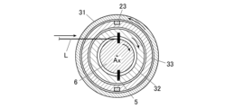
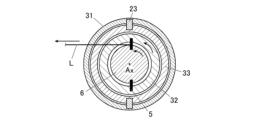
- FIG. 5A to 5C are diagrams for explaining the operation of the reel device 1.
- FIG. 5A when the fishing line L is wound, as shown in FIG. 5A, when the user rotates the handle 2, the outer rotor 31 of the transmission mechanism 3 connected to the handle 2 also rotates in the same direction. .
- the outer rotor 31 rotates, the spatial magnetic flux waveform of the outer pole magnets 31a is modulated by the magnetic pole pieces 33a of the stator 33, and rotational torque is transmitted to the inner rotor 32 (rotating in the opposite direction).
- the gear ratio becomes the number of outer pole pairs/the number of inner pole pairs, and the speed is increased in this embodiment.
- the spool 6, which is connected to the inner rotor 32 via the clutch 5, also rotates in the same direction as the inner rotor 32, and the fishing line L is reeled in at an increased speed.
- the spool 6 rotates in a direction opposite to that during line winding, and the inner side connected to the spool 6 rotates as shown in FIG. 5B.
- the rotor 32 also rotates in the same direction.
- the inner rotor 32 rotates, the outer rotor 31 also tries to rotate in the direction opposite to the direction during line winding. cannot rotate.
- the inner rotor 32 is out of step and rotates independently of the outer rotor 31, and drag starts.
- FIG. 5C the fishing line L is pulled out from the spool 6 and dragged.
- the transmission mechanism 3 when the user rotates the drag screw 34, the inner pole magnet 32b moves in the axial direction. As a result, the axial length (that is, the torque transmission area) of the inner pole magnet 32b, the outer pole magnet 31a, and the magnetic pole piece 33a are changed to change the out-of-step torque and thus the drag force (tension of the fishing line L when the drag is generated). can be adjusted.
- the outer rotor 31 or the stator 33 may be axially moved instead of the inner rotor 32 (inner pole magnet 32b). That is, the transmission mechanism 3 may be configured such that at least one of the stator 33, the outer rotor 31, and the inner rotor 32 is axially movable. However, it is more preferable to move the stator 33 in terms of generating a large torque change with a small amount of movement.
- the rotational force input to the steering wheel 2 is changed in speed by magnetic modulation in the speed change mechanism 3 and transmitted to the spool 6 .
- power torque
- torque can be transmitted from the handle 2 to the spool 6 in a non-contact manner, suppressing power loss at the contact points and changes in characteristics due to contact conditions that occur with mechanical (contact) torque transmission mechanisms.
- the amount of maintenance required in the past to suppress these problems can be greatly reduced. Therefore, it is possible to suitably transmit the rotational torque.
- clutch return is a phenomenon in which the clutch is suddenly released when the spool rotates at a high speed, and the main gear (transmission mechanism) is engaged.
- the main gear (transmission mechanism 3) of the magnetic modulation method of the present embodiment performs non-contact power transmission and has a torque limit function, so even if clutch return occurs, there is little possibility of failure.
- the outer rotor 31 connected to the handle 2 and the inner rotor 32 connected to the spool 6 are out of synchronism to enable dragging.
- drag force variation factors include aging, environmental dependence, rotational speed of the spool 6, and frictional heat due to continuous pulling of the fishing line L.
- bait reels are said to have a drag position farther from the spool axis due to their structure, resulting in lower drag operating performance than spinning reels.
- a baitcasting reel that has a drag from the spool via the main gear (transmission mechanism) has a lower drag performance than a spinning reel that has a drag directly under the spool shaft (due to disturbance factors such as the main gear and clutch). , it is difficult to obtain a good torque limit function).
- the transmission mechanism 3 is configured so that at least one of the stator 33, the outer rotor 31 and the inner rotor 32 can move in the axial direction. As a result, the torque transmission area in the speed change mechanism 3 can be changed to adjust the out-of-step torque and thus the drag force.
- the reel device 1 when the spool 6 winds the fishing line L, the outer rotor 31 and the inner rotor 32 rotate in opposite directions.
- the reel device 1 can be used with the same feel as a conventional bait reel in which the handle and the spool are connected by a mechanical gear.
- the steering wheel 2, the transmission mechanism 3, and the spool 6 have the same central axis Ax, that is, their rotation central axes are positioned on the same straight line.
- Ax central axis of rotation of the handle and the spool are displaced in parallel due to the interposition of mechanical gears
- the user's torque on the handle tends to generate a moment that rotates the reel itself around the rotation center axis of the spool. can be suppressed. Therefore, the user can easily apply force to the handle 2 and can wind the fishing line L favorably.
- FIG. 6 is a cross-sectional view schematically showing a reel device 1A according to a first modified example of the above embodiment.
- the reel device 1A according to this modified example differs from the reel device 1 of the above-described embodiment in that the outer rotor 31 and the inner rotor 32 are connected by the second one-way clutch 35 .
- a second one-way clutch 35 is provided between the arm 22 of the handle 2 fixed to the outer rotor 31 and the shaft 32a of the inner rotor 32 .
- This second one-way clutch 35 is an example of the one-way clutch according to the present invention. , and when the inner rotor 32 rotates in the direction in which the spool 6 reels out the fishing line L, the outer rotor 31 and the inner rotor 32 are constrained to rotate in the same direction. .
- the second one-way clutch 35 permits the rotation of the outer rotor 31 and the inner rotor 32 when they rotate in directions opposite to each other, and restrains them when they rotate in the same direction. good.
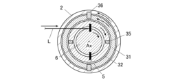
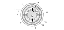
- FIG. 7A and 7B are diagrams for explaining the operation of the reel device 1A.
- the reel device 1A when the fishing line L is wound, the user rotates the handle 2 as shown in FIG. A fishing line L is wound up.
- the outer rotor 31 and the inner rotor 32 rotate in opposite directions, the second one-way clutch 35 does not restrict the rotation.
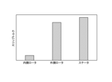
- FIG. 8A is a diagram showing an example of slip torque (out-of-step torque) waveforms of the outer rotor 31, the inner rotor 32, and the stator 33 when the stator 33 is forcibly rotated
- FIG. 8B shows torque peak values at this time. It is a figure which compared. As shown in these figures, the inner rotor 32 is accelerated, so its slip torque is relatively small. On the other hand, the slip torque of the outer rotor 31 and the stator 33 is larger than that of the inner rotor 32 by the reduction ratio, and the slip torque of the stator 33 is the largest. Therefore, by rotating the outer rotor 31 and the inner rotor 32 while restraining them, only the stator 33 is equivalently rotated, so the slip torque and drag force increase.
- the second one-way clutch 35 that connects the outer rotor 31 and the inner rotor 32 rotates when the inner rotor 32 rotates in the direction in which the spool 6 lets out the fishing line L. 31 and inner rotor 32 are restrained to rotate in the same direction.
- the out-of-step torque can be increased compared to the case where only the inner rotor 32 is out-of-step, and the drag force can be increased.
- FIG. 9 is a cross-sectional view schematically showing a reel device 1B according to a second modification of the above embodiment.
- the reel device 1B according to this modified example differs from the reel device 1A of the first modified example in that it includes a friction-type second clutch 36 that connects the handle 2 and the outer rotor 31.
- the second clutch 36 integrally rotates the handle 2 and the outer rotor 31 when the constraint torque is less than a predetermined value, and relatively rotates (slips) them when the constraint torque is greater than or equal to the predetermined value.
- FIG. 10A to 10C are diagrams for explaining the operation of the reel device 1B.
- the reel device 1B when the fishing line L is wound, the user rotates the handle 2 as shown in FIG. A fishing line L is wound up.
- the steering wheel 2 and the outer rotor 31 are connected via the friction-type second clutch 36 that slips at a predetermined torque.
- a frictional drag force is obtained at the second clutch 36 in the same manner as a conventional drag. Also, even if the rotation of the handle 2 is restrained during dragging, the line is not locked.
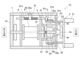
- FIG. 11 is a cross-sectional view schematically showing a reel device 1C according to a third modified example of the above embodiment. As shown in this figure, the reel device 1C according to this modification differs from the reel device 1 of the above-described embodiment in that a level wind mechanism (level winder) 8 is provided.
- a level wind mechanism level winder 8
- the level wind mechanism 8 uniformly winds the fishing line L around the spool 6 by winding the fishing line L around the spool 6 while moving it laterally (in the axial direction).
- the level wind mechanism 8 includes a worm shaft 81 , a moving member 82 and a driving gear 83 .
- the worm shaft 81 is arranged on the outer diameter side of the spool 6 while extending parallel to the central axis Ax, and is rotatably supported by the frame 10 .
- a gear 81 a is formed in a portion of the worm shaft 81 corresponding to the spool 6 .
- a pinion gear 81b is provided at the end of the worm shaft 81 opposite to the input side.
- the moving member 82 meshes with the gear 81a of the worm shaft 81, and is provided so as to reciprocate in the axial direction as the worm shaft 81 rotates.
- the moving member 82 has a through hole 82a for guiding the fishing line L.
- the drive gear 83 is integrally provided on the spool shaft 61 and meshes with the pinion gear 81 b of the worm shaft 81 .
- the worm shaft 81 also rotates because the drive gear 83 that rotates integrally with the spool 6 meshes with the pinion gear 81b as the spool 6 rotates.
- the moving member 82 reciprocates in the axial direction, and the fishing line L inserted through the through hole 82a of the worm shaft 81 also moves in the axial direction and is wound up (or unwound) on the spool 6 .
- the level wind mechanism 8 is not limited to the structure described above, and conventionally known structure of the same mechanism can be applied.
- the level wind mechanism 8 of this modified example can be suitably applied not only to the above embodiment but also to other modified examples.
- the level wind mechanism 8 may have a structure in which its driving force (rotational force of the worm shaft 81) is transmitted in a non-contact manner.
- a worm shaft magnet 81c instead of the pinion gear 81b and the drive gear 83, a worm shaft magnet 81c may be provided.
- the worm shaft magnet 81c is formed in the shape of a disk coaxial with the worm shaft 81 and is provided at the input side end of the worm shaft 81. are arranged opposite each other.
- the outer pole magnet 31a of the outer rotor 31 has an end opposite to the input side facing the worm shaft magnet 81c in the radial direction, and the other portion is supported by the yoke 31b.
- the worm shaft magnet 81c has a plurality of magnets (not shown) in which a plurality of magnets with different polarities are alternately arranged in the circumferential direction, and is magnetically coupled to the outer pole magnet 31a of the outer rotor 31. there is Therefore, the worm shaft 81 rotates with the rotation of the outer rotor 31, and the moving member 82 moves. This allows the level wind mechanism 8 to function. It should be noted that the worm shaft 81 is not limited to the configuration described above, and may be configured to rotate by magnetic force as the outer rotor 31 rotates.
- the present invention is not limited to the above embodiments.
- a reel device for fishing has been described as an example.
- the reel device according to the present invention is not limited to fishing, but can be widely applied to general reel devices for winding and feeding string-like bodies.
- the string-like object to be wound by the reel device is not limited to a fishing line, but includes a wide range of string-like objects such as wire.
- the reel device according to the present invention can also be applied to electric reels.
- the clutch 5 connects the speed change mechanism 3 and the spool 6 by magnetic force, but the clutch 5 may be a conventional mechanical (friction) clutch.
- each part of the reel device 1 (especially the magnets and magnetic pole pieces of each part) is preferably coated with a water-resistant coating to suppress corrosion by water (especially seawater).
- the present invention is useful for suitably transmitting rotational torque.
Landscapes
- Life Sciences & Earth Sciences (AREA)
- Environmental Sciences (AREA)
- Animal Husbandry (AREA)
- Biodiversity & Conservation Biology (AREA)
- Engineering & Computer Science (AREA)
- Power Engineering (AREA)
Priority Applications (3)
| Application Number | Priority Date | Filing Date | Title |
|---|---|---|---|
| EP22898211.2A EP4437846A4 (en) | 2021-11-24 | 2022-09-16 | REEL DEVICE |
| JP2023563528A JP7843776B2 (ja) | 2021-11-24 | 2022-09-16 | リール装置 |
| US18/669,074 US20240306623A1 (en) | 2021-11-24 | 2024-05-20 | Reel device |
Applications Claiming Priority (2)
| Application Number | Priority Date | Filing Date | Title |
|---|---|---|---|
| JP2021-189802 | 2021-11-24 | ||
| JP2021189802 | 2021-11-24 |
Related Child Applications (1)
| Application Number | Title | Priority Date | Filing Date |
|---|---|---|---|
| US18/669,074 Continuation US20240306623A1 (en) | 2021-11-24 | 2024-05-20 | Reel device |
Publications (1)
| Publication Number | Publication Date |
|---|---|
| WO2023095426A1 true WO2023095426A1 (ja) | 2023-06-01 |
Family
ID=86539185
Family Applications (1)
| Application Number | Title | Priority Date | Filing Date |
|---|---|---|---|
| PCT/JP2022/034662 Ceased WO2023095426A1 (ja) | 2021-11-24 | 2022-09-16 | リール装置 |
Country Status (4)
| Country | Link |
|---|---|
| US (1) | US20240306623A1 (https=) |
| EP (1) | EP4437846A4 (https=) |
| JP (1) | JP7843776B2 (https=) |
| WO (1) | WO2023095426A1 (https=) |
Cited By (1)
| Publication number | Priority date | Publication date | Assignee | Title |
|---|---|---|---|---|
| WO2025115518A1 (ja) * | 2023-11-30 | 2025-06-05 | 住友重機械工業株式会社 | リール装置 |
Citations (13)
| Publication number | Priority date | Publication date | Assignee | Title |
|---|---|---|---|---|
| US3378710A (en) * | 1964-06-01 | 1968-04-16 | Micro Pump Corp | Magnetic transmission |
| JPS58117866U (ja) * | 1982-02-03 | 1983-08-11 | ダイワ精工株式会社 | 魚釣用リ−ルのバツクラツシユ防止装置 |
| JPS6375172U (https=) * | 1986-10-31 | 1988-05-19 | ||
| JP2004033024A (ja) * | 2002-06-28 | 2004-02-05 | Daiwa Seiko Inc | 魚釣用電動リール |
| JP2004081114A (ja) * | 2002-08-27 | 2004-03-18 | Daiwa Seiko Inc | 魚釣用リール |
| JP2004173516A (ja) * | 2002-11-25 | 2004-06-24 | Daiwa Seiko Inc | 魚釣用リール |
| JP3120657U (ja) * | 2005-12-16 | 2006-04-20 | 公治 竹内 | 魚釣り用リールの歯車装置 |
| JP2014161162A (ja) * | 2013-02-20 | 2014-09-04 | Seiko Epson Corp | 電気機械装置、ロボット、及び移動体 |
| JP2016214123A (ja) * | 2015-05-19 | 2016-12-22 | グローブライド株式会社 | 魚釣用リール |
| JP2018113918A (ja) | 2017-01-19 | 2018-07-26 | 株式会社シマノ | 両軸受リール |
| CN108935361A (zh) * | 2018-09-17 | 2018-12-07 | 慈溪德宝渔具有限公司 | 一种渔轮可以控制线轮转速的磁力刹车机构 |
| JP2022098036A (ja) | 2020-12-21 | 2022-07-01 | グローブライド株式会社 | 両軸受けリール |
| JP2022108840A (ja) | 2021-01-14 | 2022-07-27 | シマノコンポネンツ マレーシア エスディーエヌ.ビーエッチディー. | 両軸受リール |
Family Cites Families (2)
| Publication number | Priority date | Publication date | Assignee | Title |
|---|---|---|---|---|
| CN205161638U (zh) * | 2015-11-17 | 2016-04-20 | 慈溪市永杰精工渔具有限公司 | 一种通过磁力调节转速的实现缓速下降的筏钓轮 |
| CN212306564U (zh) * | 2020-07-16 | 2021-01-08 | 何杰平 | 一种防炸线的路亚轮 |
-
2022
- 2022-09-16 WO PCT/JP2022/034662 patent/WO2023095426A1/ja not_active Ceased
- 2022-09-16 JP JP2023563528A patent/JP7843776B2/ja active Active
- 2022-09-16 EP EP22898211.2A patent/EP4437846A4/en active Pending
-
2024
- 2024-05-20 US US18/669,074 patent/US20240306623A1/en active Pending
Patent Citations (13)
| Publication number | Priority date | Publication date | Assignee | Title |
|---|---|---|---|---|
| US3378710A (en) * | 1964-06-01 | 1968-04-16 | Micro Pump Corp | Magnetic transmission |
| JPS58117866U (ja) * | 1982-02-03 | 1983-08-11 | ダイワ精工株式会社 | 魚釣用リ−ルのバツクラツシユ防止装置 |
| JPS6375172U (https=) * | 1986-10-31 | 1988-05-19 | ||
| JP2004033024A (ja) * | 2002-06-28 | 2004-02-05 | Daiwa Seiko Inc | 魚釣用電動リール |
| JP2004081114A (ja) * | 2002-08-27 | 2004-03-18 | Daiwa Seiko Inc | 魚釣用リール |
| JP2004173516A (ja) * | 2002-11-25 | 2004-06-24 | Daiwa Seiko Inc | 魚釣用リール |
| JP3120657U (ja) * | 2005-12-16 | 2006-04-20 | 公治 竹内 | 魚釣り用リールの歯車装置 |
| JP2014161162A (ja) * | 2013-02-20 | 2014-09-04 | Seiko Epson Corp | 電気機械装置、ロボット、及び移動体 |
| JP2016214123A (ja) * | 2015-05-19 | 2016-12-22 | グローブライド株式会社 | 魚釣用リール |
| JP2018113918A (ja) | 2017-01-19 | 2018-07-26 | 株式会社シマノ | 両軸受リール |
| CN108935361A (zh) * | 2018-09-17 | 2018-12-07 | 慈溪德宝渔具有限公司 | 一种渔轮可以控制线轮转速的磁力刹车机构 |
| JP2022098036A (ja) | 2020-12-21 | 2022-07-01 | グローブライド株式会社 | 両軸受けリール |
| JP2022108840A (ja) | 2021-01-14 | 2022-07-27 | シマノコンポネンツ マレーシア エスディーエヌ.ビーエッチディー. | 両軸受リール |
Non-Patent Citations (1)
| Title |
|---|
| See also references of EP4437846A4 |
Cited By (1)
| Publication number | Priority date | Publication date | Assignee | Title |
|---|---|---|---|---|
| WO2025115518A1 (ja) * | 2023-11-30 | 2025-06-05 | 住友重機械工業株式会社 | リール装置 |
Also Published As
| Publication number | Publication date |
|---|---|
| JP7843776B2 (ja) | 2026-04-10 |
| EP4437846A1 (en) | 2024-10-02 |
| US20240306623A1 (en) | 2024-09-19 |
| JPWO2023095426A1 (https=) | 2023-06-01 |
| EP4437846A4 (en) | 2025-03-26 |
Similar Documents
| Publication | Publication Date | Title |
|---|---|---|
| JP6514066B2 (ja) | 両軸受リール | |
| US8256598B2 (en) | Permanent magnet wrap spring clutch | |
| WO2023095426A1 (ja) | リール装置 | |
| KR102812743B1 (ko) | 스풀을 제동하는 제동 장치 및 이것을 구비한 낚시용 릴 | |
| JP5529689B2 (ja) | 負荷感応型自動変速装置を内蔵した巻上機 | |
| KR102819842B1 (ko) | 스풀을 제동하는 제동 장치 및 이를 구비한 낚시용 릴 | |
| KR102823336B1 (ko) | 스풀을 제동하는 제동 장치 및 이를 구비한 낚시용 릴 | |
| JP6342218B2 (ja) | 電動リールのモータ制御装置 | |
| JP7544673B2 (ja) | 魚釣用リール | |
| CN102192252A (zh) | 一种电磁离合器 | |
| EP3911868B1 (en) | Rotational coupling device with armature release collar | |
| JP6416693B2 (ja) | 魚釣用リール | |
| JP6449718B2 (ja) | 魚釣用リール | |
| JP6829020B2 (ja) | 両軸受リール | |
| KR20090076824A (ko) | 디클러칭 메커니즘 | |
| JP2025088199A (ja) | リール装置 | |
| JP3515882B2 (ja) | 魚釣用リール | |
| KR102706599B1 (ko) | 베이트릴용 다극 마그넷 브레이크 | |
| CN2731168Y (zh) | 扭簧电磁离合器 | |
| JPH10262521A (ja) | 魚釣用リール | |
| US12219942B2 (en) | Automatically adjusting variable gear ratio fishing reel | |
| JP7513573B2 (ja) | 電動巻き上げ装置及び魚釣用電動リール | |
| JP7616966B2 (ja) | 電動巻き上げ装置 | |
| WO2025104943A1 (ja) | 制動装置、及び魚釣用リール | |
| JP2020092659A (ja) | ベイトリール、ベイトリールに用いられる電磁ブレーキおよびベイトリール用スプール |
Legal Events
| Date | Code | Title | Description |
|---|---|---|---|
| 121 | Ep: the epo has been informed by wipo that ep was designated in this application |
Ref document number: 22898211 Country of ref document: EP Kind code of ref document: A1 |
|
| WWE | Wipo information: entry into national phase |
Ref document number: 2023563528 Country of ref document: JP |
|
| WWE | Wipo information: entry into national phase |
Ref document number: 2022898211 Country of ref document: EP |
|
| NENP | Non-entry into the national phase |
Ref country code: DE |
|
| ENP | Entry into the national phase |
Ref document number: 2022898211 Country of ref document: EP Effective date: 20240624 |