WO2023095352A1 - 媒体給送装置 - Google Patents
媒体給送装置 Download PDFInfo
- Publication number
- WO2023095352A1 WO2023095352A1 PCT/JP2021/043697 JP2021043697W WO2023095352A1 WO 2023095352 A1 WO2023095352 A1 WO 2023095352A1 JP 2021043697 W JP2021043697 W JP 2021043697W WO 2023095352 A1 WO2023095352 A1 WO 2023095352A1
- Authority
- WO
- WIPO (PCT)
- Prior art keywords
- roller
- medium
- feeding
- separation roller
- separation
- Prior art date
- Legal status (The legal status is an assumption and is not a legal conclusion. Google has not performed a legal analysis and makes no representation as to the accuracy of the status listed.)
- Ceased
Links
Images





Classifications
-
- B—PERFORMING OPERATIONS; TRANSPORTING
- B65—CONVEYING; PACKING; STORING; HANDLING THIN OR FILAMENTARY MATERIAL
- B65H—HANDLING THIN OR FILAMENTARY MATERIAL, e.g. SHEETS, WEBS, CABLES
- B65H5/00—Feeding articles separated from piles; Feeding articles to machines
- B65H5/06—Feeding articles separated from piles; Feeding articles to machines by rollers or balls, e.g. between rollers
-
- B—PERFORMING OPERATIONS; TRANSPORTING
- B65—CONVEYING; PACKING; STORING; HANDLING THIN OR FILAMENTARY MATERIAL
- B65H—HANDLING THIN OR FILAMENTARY MATERIAL, e.g. SHEETS, WEBS, CABLES
- B65H3/00—Separating articles from piles
- B65H3/02—Separating articles from piles using friction forces between articles and separator
- B65H3/06—Rollers or like rotary separators
-
- B—PERFORMING OPERATIONS; TRANSPORTING
- B65—CONVEYING; PACKING; STORING; HANDLING THIN OR FILAMENTARY MATERIAL
- B65H—HANDLING THIN OR FILAMENTARY MATERIAL, e.g. SHEETS, WEBS, CABLES
- B65H3/00—Separating articles from piles
- B65H3/02—Separating articles from piles using friction forces between articles and separator
- B65H3/06—Rollers or like rotary separators
- B65H3/0638—Construction of the rollers or like rotary separators
-
- B—PERFORMING OPERATIONS; TRANSPORTING
- B65—CONVEYING; PACKING; STORING; HANDLING THIN OR FILAMENTARY MATERIAL
- B65H—HANDLING THIN OR FILAMENTARY MATERIAL, e.g. SHEETS, WEBS, CABLES
- B65H3/00—Separating articles from piles
- B65H3/02—Separating articles from piles using friction forces between articles and separator
- B65H3/06—Rollers or like rotary separators
- B65H3/0669—Driving devices therefor
-
- B—PERFORMING OPERATIONS; TRANSPORTING
- B65—CONVEYING; PACKING; STORING; HANDLING THIN OR FILAMENTARY MATERIAL
- B65H—HANDLING THIN OR FILAMENTARY MATERIAL, e.g. SHEETS, WEBS, CABLES
- B65H3/00—Separating articles from piles
- B65H3/02—Separating articles from piles using friction forces between articles and separator
- B65H3/06—Rollers or like rotary separators
- B65H3/0684—Rollers or like rotary separators on moving support, e.g. pivoting, for bringing the roller or like rotary separator into contact with the pile
-
- B—PERFORMING OPERATIONS; TRANSPORTING
- B65—CONVEYING; PACKING; STORING; HANDLING THIN OR FILAMENTARY MATERIAL
- B65H—HANDLING THIN OR FILAMENTARY MATERIAL, e.g. SHEETS, WEBS, CABLES
- B65H3/00—Separating articles from piles
- B65H3/46—Supplementary devices or measures to assist separation or prevent double feed
- B65H3/52—Friction retainers acting on under or rear side of article being separated
- B65H3/5207—Non-driven retainers, e.g. movable retainers being moved by the motion of the article
- B65H3/5215—Non-driven retainers, e.g. movable retainers being moved by the motion of the article the retainers positioned under articles separated from the top of the pile
- B65H3/5223—Retainers of the pad-type, e.g. friction pads
-
- B—PERFORMING OPERATIONS; TRANSPORTING
- B65—CONVEYING; PACKING; STORING; HANDLING THIN OR FILAMENTARY MATERIAL
- B65H—HANDLING THIN OR FILAMENTARY MATERIAL, e.g. SHEETS, WEBS, CABLES
- B65H3/00—Separating articles from piles
- B65H3/46—Supplementary devices or measures to assist separation or prevent double feed
- B65H3/52—Friction retainers acting on under or rear side of article being separated
- B65H3/5246—Driven retainers, i.e. the motion thereof being provided by a dedicated drive
- B65H3/5253—Driven retainers, i.e. the motion thereof being provided by a dedicated drive the retainers positioned under articles separated from the top of the pile
- B65H3/5261—Retainers of the roller type, e.g. rollers
-
- B—PERFORMING OPERATIONS; TRANSPORTING
- B65—CONVEYING; PACKING; STORING; HANDLING THIN OR FILAMENTARY MATERIAL
- B65H—HANDLING THIN OR FILAMENTARY MATERIAL, e.g. SHEETS, WEBS, CABLES
- B65H3/00—Separating articles from piles
- B65H3/46—Supplementary devices or measures to assist separation or prevent double feed
- B65H3/56—Elements, e.g. scrapers, fingers, needles, brushes, acting on separated article or on edge of the pile
-
- B—PERFORMING OPERATIONS; TRANSPORTING
- B65—CONVEYING; PACKING; STORING; HANDLING THIN OR FILAMENTARY MATERIAL
- B65H—HANDLING THIN OR FILAMENTARY MATERIAL, e.g. SHEETS, WEBS, CABLES
- B65H2404/00—Parts for transporting or guiding the handled material
- B65H2404/10—Rollers
- B65H2404/13—Details of longitudinal profile
- B65H2404/131—Details of longitudinal profile shape
- B65H2404/1316—Details of longitudinal profile shape stepped or grooved
- B65H2404/13161—Regularly spaced grooves
-
- B—PERFORMING OPERATIONS; TRANSPORTING
- B65—CONVEYING; PACKING; STORING; HANDLING THIN OR FILAMENTARY MATERIAL
- B65H—HANDLING THIN OR FILAMENTARY MATERIAL, e.g. SHEETS, WEBS, CABLES
- B65H2801/00—Application field
- B65H2801/03—Image reproduction devices
- B65H2801/12—Single-function printing machines, typically table-top machines
Definitions
- the present disclosure relates to a medium feeding device.
- a medium feeding device such as a scanner uses a feeding roller and a separation roller to separate and feed media.
- Foreign matter such as paper dust, filler, coating agent (pigment), and powder may adhere to the medium fed by such a medium feeding device.
- a feeding roller has been developed in which a groove capable of containing foreign matter is formed.
- a paper feed roller made of a rubber composition and provided with unevenness on the roller surface has been disclosed (see Patent Document 1).
- Media feeding devices are required to be able to feed media better.
- the object of the medium feeding device according to the embodiment is to feed the medium more satisfactorily.
- a medium feeding device includes a feeding roller for feeding a medium, a separation roller made of resin and arranged to face the feeding roller, and a feeding roller.
- a pressing portion that presses one of the feeding roller and the separation roller against the other such that a nip region is formed at a position where the separation roller contacts the feeding roller;
- a plurality of grooves arranged perpendicular to the feeding direction are formed, the pitch of the plurality of grooves is set such that there is always at least one groove in the nip region during medium feeding;
- the width of the groove is set to 0.5 mm or more, and the contact area ratio S is set to 0.5 or more. area of the feed roller groove) ⁇ /(surface area of the feed roller in the nip region).
- the medium feeding device can feed the medium more satisfactorily.
- FIG. 1 is a perspective view showing a medium feeding device 100 according to an embodiment
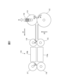
- FIG. 4 is a diagram for explaining a transport path inside the medium feeding device 100
- FIG. FIG. 4 is a schematic diagram for explaining forces applied to each roller
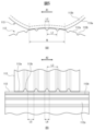
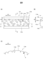
- It is a schematic diagram for demonstrating the surface of each roller.
- (A) and (B) are schematic diagrams for explaining grooves of respective rollers.
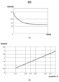
- (A) and (B) are graphs for explaining a contact area ratio S.
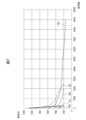
- FIG. 5 is a graph for explaining a contact area ratio S;
- (A), (B), and (C) are schematic diagrams for explaining the separation roller 113.
- FIG. Fig. 3 is a graph showing the relationship between media movement speed and amplitude;
- (A) and (B) are graphs for explaining a contact area ratio P.
- FIG. 4 is a graph showing the relationship between frequency and sound pressure;
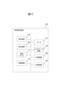
- 2 is a block diagram showing a schematic configuration of the medium feeding device 100;
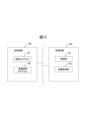
- FIG. 2 is a diagram showing a schematic configuration of a storage device 140 and a processing circuit 150;
- FIG. 7 is a flow chart showing an example of the operation of medium reading processing;
- FIG. 11 is a schematic diagram for explaining another separation roller 213;
- 3 is a diagram showing a schematic configuration of another processing circuit 350;
- FIG. 1 is a perspective view showing a medium feeding device 100 configured as an image scanner.
- the medium feeding device 100 feeds and conveys a medium, which is an original, and picks up an image.
- the medium may be paper, thin paper, cardboard, card, booklet, envelope, or the like. Foreign matter such as paper dust, filler that adheres to the paper during paper production, coating agent (pigment) that adheres to coated paper, and powder that adheres during color printing adheres to the medium to be fed.
- the media feeding device 100 may be a facsimile machine, a copier, a multifunction peripheral (MFP), or the like. It should be noted that the medium to be conveyed may be a print object or the like instead of the document, and the medium feeding device 100 may be a printer or the like.
- the medium feeding device 100 includes a lower housing 101, an upper housing 102, a mounting table 103, a discharge table 104, an operation device 105, a display device 106, and the like.
- arrow A1 indicates the medium transport direction
- arrow A2 indicates the width direction orthogonal to the medium transport direction
- arrow A3 indicates the height direction orthogonal to the medium transport surface.
- upstream refers to upstream in the medium transport direction A1
- downstream refers to downstream in the medium transport direction A1.
- the upper housing 102 is positioned to cover the upper surface of the medium feeding device 100, and rotates to the lower housing 101 with a hinge so that it can be opened and closed when the medium is clogged or when cleaning the inside of the medium feeding device 100. engaged as possible.
- the mounting table 103 engages with the lower housing 101 and mounts a medium to be fed and transported.
- the ejection table 104 engages with the upper housing 102 and places the ejected medium. Note that the discharge table 104 may be engaged with the lower housing 101 .
- the operation device 105 has an input device such as a button and an interface circuit that acquires signals from the input device, receives an input operation by the user, and outputs an operation signal according to the user's input operation.
- the display device 106 has a display including liquid crystal, organic EL (Electro-Luminescence), etc. and an interface circuit for outputting image data to the display, and displays the image data on the display.
- FIG. 2 is a diagram for explaining the transport path inside the medium feeding device 100.
- FIG. 2 is a diagram for explaining the transport path inside the medium feeding device 100.
- the transport path inside the medium feeding device 100 includes a medium sensor 111, a feeding roller 112, a separation roller 113, a first transport roller 114, a first opposing roller 115, an imaging device 116, a second transport roller 117, and a second opposing roller. 118 and the like.
- each of the feeding roller 112, the separating roller 113, the first conveying roller 114, the first facing roller 115, the second conveying roller 117 and/or the second facing roller 118 is not limited to one, and may be plural. good.
- the feeding roller 112, the separating roller 113, the first conveying roller 114, the first facing roller 115, the second conveying roller 117 and/or the second facing roller 118 are arranged in the width direction A2 orthogonal to the medium conveying direction. They are arranged side by side at intervals.
- the upper surface of the lower housing 101 forms the lower guide 101a of the medium transport path
- the lower surface of the upper housing 102 forms the upper guide 102a of the medium transport path.
- the medium sensor 111 is arranged upstream from the feed roller 112 and the separation roller 113 .
- the medium sensor 111 has a contact detection sensor and detects whether or not a medium is mounted on the mounting table 103 .
- the medium sensor 111 generates and outputs a medium signal whose signal value changes depending on whether the medium is mounted on the mounting table 103 or not.
- the medium sensor 111 is not limited to a contact detection sensor, and any other sensor capable of detecting the presence or absence of a medium, such as a light detection sensor, may be used as the medium sensor 111 .
- the feeding roller 112 is provided in the lower housing 101, and separates and feeds the medium placed on the placing table 103 in order from the bottom.
- the feed roller 112 is made of resin such as rubber or plastic, metal such as iron, or the like.
- the separation roller 113 is a so-called brake roller or retard roller, is provided in the upper housing 102 , and is arranged to face the feeding roller 112 .
- the separation roller 113 is provided rotatably or stopably in the direction opposite to the medium feeding direction.
- the separation roller 113 is made of resin such as rubber or plastic, metal such as iron, or the like. Note that the feeding roller 112 is provided in the upper housing 102 and the separation roller 113 is provided in the lower housing 101, and the feeding roller 112 feeds the medium placed on the mounting table 103 in order from the top. good.
- the first conveying roller 114 and the first opposing roller 115 are arranged downstream of the feeding roller 112 and the separating roller 113 in the medium conveying direction A1.
- the first conveying roller 114 is provided in the upper housing 102 and conveys the medium fed by the feeding roller 112 and separation roller 113 to the imaging device 116 .
- the first conveying roller 114 is made of resin such as rubber or plastic, metal such as iron, or the like.
- the first facing roller 115 is provided in the lower housing 101 below the first conveying roller 114 so as to face the first conveying roller 114 , and rotates following the first conveying roller 114 .
- the first opposed roller 115 is made of resin such as rubber or plastic, metal such as iron, or the like. Note that the first conveying roller 114 may be provided on the lower housing 101 and the first opposing roller 115 may be provided on the upper housing 102 .
- the imaging device 116 is an example of an imaging unit, is arranged downstream of the first transport rollers 114 and the first opposing rollers 115 in the medium transport direction A1, and is transported by the first transport rollers 114 and the first opposing rollers 115. image the medium.
- the image pickup device 116 includes a first image pickup device 116a and a second image pickup device 116b arranged to face each other with the medium transport path interposed therebetween.
- the first imaging device 116a has a linear optical system type CIS (Contact Image Sensor) line sensor having CMOS (Complementary Metal Oxide Semiconductor) imaging elements arranged linearly in the main scanning direction. Also, the first imaging device 116a has a lens that forms an image on an imaging device, and an A/D converter that amplifies an electrical signal output from the imaging device and performs analog/digital (A/D) conversion. The first imaging device 116a captures an image of the surface of the medium being conveyed, generates an input image, and outputs the input image, under the control of a processing circuit, which will be described later.
- CIS Contact Image Sensor
- CMOS Complementary Metal Oxide Semiconductor
- the second imaging device 116b has a linear optical system type CIS line sensor having CMOS imaging elements linearly arranged in the main scanning direction.
- the second imaging device 116b also has a lens that forms an image on the imaging device, and an A/D converter that amplifies the electrical signal output from the imaging device and performs analog/digital (A/D) conversion.
- the second image capturing device 116b captures an image of the back surface of the medium being conveyed, generates an input image, and outputs the input image, under the control of a processing circuit, which will be described later.
- the medium feeding device 100 may have only one of the first imaging device 116a and the second imaging device 116b and read only one side of the medium.
- a line sensor of the same magnification optical system type CIS provided with the CMOS imaging device a line sensor of the same magnification optical system type CIS provided with the CCD (Charge Coupled Device) imaging device may be used.
- a reduction optics type line sensor having a CMOS or CCD imaging device may be used.
- the second conveying roller 117 and the second opposing roller 118 are arranged downstream from the imaging device 116, that is, from the feeding roller 112 and the separating roller 113 in the medium conveying direction A1.
- the second transport roller 117 is provided in the upper housing 102 , transports the medium transported by the first transport roller 114 and the first opposed roller 115 further downstream, and discharges the medium to the discharge table 104 .
- the second conveying roller 117 is made of resin such as rubber or plastic, metal such as iron, or the like.
- the second opposing roller 118 is provided in the lower housing 101 below the second transport roller 117 so as to face the second transport roller 117 , and rotates following the second transport roller 117 .
- the second opposing roller 118 is made of resin such as rubber or plastic, metal such as iron, or the like.
- the second conveying roller 117 may be provided on the lower housing 101 and the second facing roller 118 may be provided on the upper housing 102 .
- the feeding roller 112 rotates in the direction of the arrow A4, that is, in the medium feeding direction
- the medium placed on the mounting table 103 moves between the lower guide 101a and the upper guide 102a in the medium conveying direction A1.
- the separation roller 113 rotates or stops in the direction of arrow A5, that is, the direction opposite to the medium feeding direction.
- the medium is fed between the first conveying roller 114 and the first opposing roller 115 while being guided by the lower guide 101a and the upper guide 102a.
- the medium is fed between the first imaging device 116a and the second imaging device 116b by rotating the first transport roller 114 in the direction of arrow A6.
- the medium read by the imaging device 116 is discharged onto the discharge table 104 as the second transport roller 117 rotates in the direction of arrow A7.
- FIG. 3 is a schematic diagram for explaining forces applied to the feeding roller 112 and the separation roller 113.
- FIG. 3 is a schematic diagram for explaining forces applied to the feeding roller 112 and the separation roller 113.
- the medium feeding device 100 further has a pressing member 119. As shown in FIG. 3, the medium feeding device 100 further has a pressing member 119. As shown in FIG.
- the pressing member 119 is an example of a pressing portion, one end of which is provided on the upper housing 102 and the other end of which is provided on the shaft that is the rotating shaft of the separation roller 113, and presses the separation roller 113 toward the feed roller 112 side.
- the pressing member 119 includes an elastic member such as a torsion coil spring, and generates a pressing force W that presses the separation roller 113 toward the feeding roller 112 side.
- a nip region is formed at a position where the feeding roller 112 and the separation roller 113 are in contact with each other by the pressing member 119 .
- the pressing member 119 may include other spring members such as leaf springs, rubber members, or the like.
- the pressing member 119 may be provided so as to press the feeding roller 112 toward the separation roller 113 side. In this manner, the pressing member 119 presses one of the feeding roller 112 and the separation roller 113 against the other such that a nip region is formed at the position where the feeding roller 112 and the separation roller 113 contact each other.
- FIG. 4 is a schematic diagram for explaining the surfaces of the feed roller 112 and the separation roller 113.
- FIG. FIG. 4 is a perspective view of the feed roller 112 and separation roller 113 viewed from the downstream side.
- a shaft (rotating axis of the feed roller 112) is provided in a width direction A2 perpendicular to the medium feeding direction, i.e., perpendicular to the medium feeding direction.
- a plurality of grooves 112b arranged parallel to each other are formed. That is, the plurality of grooves 112b are arranged side by side at intervals in the medium feeding direction so as to extend in the direction orthogonal to the medium feeding direction.
- the term "perpendicular to the medium feeding direction” is not limited to an angle of 90° with the medium feeding direction. For example, an angle within the range of ⁇ 5°) is also included.
- the feeding roller 112 can more efficiently peel off (scrape off) the foreign matter adhering to the medium. , and the foreign matter can be more efficiently accommodated in the groove 112b.
- a plurality of grooves are arranged in the medium conveying direction A1, that is, parallel to the medium feeding direction (perpendicular to the shaft that is the rotation axis of the separation roller 113).
- 113b is formed. That is, the plurality of grooves 113b are arranged side by side at intervals in the direction orthogonal to the medium feeding direction so as to extend in the medium feeding direction.
- parallel to the medium feeding direction is not limited to an angle of 0° with the medium feeding direction. For example, an angle within the range of ⁇ 5°) is also included.
- the medium feeding device 100 can suppress the occurrence of double feeding of the medium.
- the grooves 113b are arranged on the surface 113a of the separation roller 113 in parallel with the medium feeding direction, the position of the grooves 113b in the nip region N does not change when the separation roller 113 rotates, and the separation force is increased. is kept constant. As a result, the medium feeding device 100 can suppress the occurrence of double feeding of media.
- the medium feeding device 100 can suppress the occurrence of double feeding of media.
- the extending direction of the grooves 112b of the feeding roller 112 and the extending direction of the grooves 113b of the separation roller 113 are orthogonal to each other, there is a high probability that foreign matter that is frayed from the medium and extends in various directions It is housed in a ditch.
- FIG. 5A is a schematic diagram for explaining the groove 112b of the feeding roller 112.
- FIG. 5A is a schematic side view of the nip region between the feeding roller 112 and the separation roller 113.
- FIG. 5A is a schematic diagram for explaining the groove 112b of the feeding roller 112.
- FIG. 5A is a schematic side view of the nip region between the feeding roller 112 and the separation roller 113.
- a plurality of grooves 112b are formed along the circumferential direction at regular pitches L1.
- the pitch L1 of the plurality of grooves 112b is set such that there is always at least one groove 112b within the nip region N during media feeding.
- the width L2 of each groove 112b of the feeding roller 112 is set to 0.5 mm or more.
- the medium feeding device 100 can efficiently accommodate the fibers adhering to the surface 112a of the feeding roller 112 in the groove 112b. .
- the medium feeding device 100 prevents the fibers from adhering to the surface 112a of the feeding roller 112, reducing the coefficient of friction between the surface 112a of the feeding roller 112 and the medium, and preventing the medium from slipping. can. Therefore, the medium feeding device 100 can suppress the occurrence of medium jams.
- FIG. 5B is a schematic diagram for explaining the groove 113b of the separation roller 113.
- FIG. FIG. 5B is a schematic diagram of the periphery of the nip area between the feeding roller 112 and the separating roller 113 as seen from the downstream side.
- each groove 113b of the separation roller 113 is set to 0.5 mm or more.
- the medium feeding device 100 can efficiently accommodate the fibers adhering to the surface 113a of the separation roller 113 in the groove 113b.
- the medium feeding device 100 can prevent the medium from slipping due to the fibers adhering to the surface 113a of the separation roller 113 and the coefficient of friction between the surface 113a of the separation roller 113 and the medium being reduced. Therefore, the medium feeding device 100 can suppress the occurrence of medium jams.
- the contact area ratio S is set to be 0.5 or more.
- FIGS. 6A, 6B, and 7 are graphs for explaining the contact area ratio S of the feeding roller 112.
- FIG. 6A is a graph showing the relationship between the number of media fed by a feeding roller and the coefficient of friction between the feeding roller feeding that number of media and the media.
- the horizontal axis of FIG. 6A indicates the number of media fed by the feeding roller, and the vertical axis indicates the coefficient of friction between the feeding roller that has fed that number of media and the media.
- This feeding roller is a roller that does not have grooves and has a coefficient of friction with the medium of about 3.0 in the initial state (the state in which the medium has not yet been fed).
- the coefficient of friction between the feeding roller and the media decreases, increasing the possibility of media slippage.
- the frequency of occurrence of media slip rapidly increased when the coefficient of friction was less than 1.4.
- the maximum static friction force between two objects is calculated by multiplying the shear strength (constant if the materials of the objects are the same) and the area where the two objects are actually in contact. That is, the frictional force between two bodies is proportional to the contact area.
- FIG. 6(B) is a graph showing the relationship between the contact area ratio S of the feeding roller having grooves and the coefficient of friction between the feeding roller and the medium.
- the horizontal axis of FIG. 6B indicates the contact area ratio S of the feeding roller, and the vertical axis indicates the coefficient of friction between the feeding roller and the medium.
- the coefficient of friction is less than 1.4, the frequency of medium slippage is high, so the coefficient of friction is preferably 1.4 or more.
- the contact area ratio S is set by setting the threshold value (1.4) of the friction coefficient at which the frequency of medium slippage increases to the initial value (3 .0) (1.4/3.0 ⁇ 0.5) or more.
- the medium feeding device 100 can reduce the frequency of medium slippage during medium feeding.
- FIG. 7 shows the number of media fed by the feeding roller and the media feeding force ( It is a graph showing the relationship with feed force).
- the horizontal axis in FIG. 7 indicates the number of media fed by the feeding roller, and the vertical axis indicates the media feeding force by the feeding roller that has fed that number of media.
- the medium feeding force by the feeding roller 112 is a force applied to the medium fed by the feeding roller 112 in the medium feeding direction. It is measured by attaching a tension gauge.
- a graph 701 shows a graph for a feeding roller with a contact area ratio S of 0.35.
- a graph 702 shows a graph for a feeding roller with a contact area ratio S of 0.50.
- a graph 703 shows a graph for a feeding roller with a contact area ratio S of 0.60.
- a graph 704 shows a graph for a feeding roller with a contact area ratio S of 0.90.
- a graph 705 shows a graph for a feeding roller with a contact area ratio S of 0.95.
- a feeding force of 200 [gf] or more was required.
- the feeding roller with the contact area ratio S of 0.35 generates a sufficient feeding force in the initial state (the state in which the medium has not yet been fed), and feeds the medium satisfactorily. could be delivered.
- the feeding force abruptly decreases every time the medium is fed, and when about 200 sheets of media are fed, the feeding force becomes less than 200 [gf], can no longer be fed properly.
- the feeding rollers with the contact area ratio S of 0.50, 0.60, or 0.80, in the initial state and in the state of feeding 1000 or more media A sufficient feeding force was generated, and the medium could be fed satisfactorily.
- the feeding roller with the contact area ratio S of 0.95 cannot generate a sufficient feeding force in the initial state, and cannot properly feed the medium. I could't do it.
- the feeding roller 112 can feed the medium satisfactorily for a long period of time.
- the contact area ratio S is preferably set to 0.9 or less. As a result, the feeding roller 112 can continue to feed the medium satisfactorily for a long period of time from the initial state.
- the contact area ratio S of the feeding roller 112 is defined by the following formula (2) from the formula (1), and the pitch L1 of the grooves 112b of the feeding roller 112 is determined from the formula (2) by the following formula: (3).
- Contact area ratio S ⁇ (Pitch L1 of groove 112b of feeding roller 112 ⁇ Width L2 of groove 112b of feeding roller 112) ⁇ /(Width L2 of groove 112b of feeding roller 112) (2)
- Pitch L1 of groove 112b of feeding roller 112 (width L2 of groove 112b of feeding roller 112)/(1-contact area ratio S) (3)
- the pitch of the groove 112b of the feeding roller 112 is The minimum value of L1 is 1.0 mm. Also, generally, the width of the nip region between the feeding roller and the separation roller is set in the range of 4.0 mm or more and 6.0 mm or less.
- the pitch L1 of the grooves 112b of the feed roller 112 is set so that at least one groove 112b always exists within the nip area N during medium feeding, so the maximum value of the pitch L1 is 4.0 mm. is. Therefore, the pitch L1 of the plurality of grooves 112b of the feeding roller 112 is 1.0 mm or more and 4.0 mm or less.
- the width of the grooves 112b of the feeding roller 112 is The maximum value of L2 is 2.0 mm. Therefore, the width L2 of the groove 112b of the feeding roller 112 is 2.0 mm or less.
- the fiber length of 95% or more of hardwood pulp used as paper is 2.0 mm or less, and the fiber length of 50% or more of softwood pulp used as paper is 2.0 mm or less. Therefore, by setting the width L2 of the groove 112b of the feeding roller 112 to 2.0 mm, the medium feeding device 100 accommodates most of the hardwood pulp and softwood pulp fibers in the groove 112b of the feeding roller 112. be able to.
- the feeding roller 112 can efficiently accommodate foreign matter adhering to the medium to be fed in the groove 112b, and can continue to feed the medium satisfactorily for a long period of time from the initial state.
- FIG. 8A is a schematic view of the surface 113a of the separation roller 113 viewed from above
- FIG. 8B is a cross-sectional view taken along line AA' of FIG. 8A
- FIG. ) is a cross-sectional view taken along the line BB' of FIG. 8(A).
- the surface 113a of the separation roller 113 is formed with a plurality of flat portions 113c arranged between the plurality of grooves 113b.
- a plurality of openings 113d are formed in each of the plurality of flat portions 113c.
- Each opening 113d is formed by hollowing out a portion of the flat portion 113c in a hemispherical shape (dome shape). That is, each opening 113d is formed in a circular shape when viewed from above.
- each opening 113d may be formed in an arbitrary shape such as an elliptical shape, a rectangular shape, a triangular shape, or the like.
- a barking sound is a sound in a specific frequency band (eg, 3 kHz to 4 kHz, 6.5 kHz to 8 kHz, etc.).
- the vibration frequency f ss is calculated by the following formula (5), and the vibration amplitude A ss is calculated by the following formula (6).
- f ss kv/ ⁇ 2( ⁇ s ⁇ k )W ⁇ (5)
- a ss ( ⁇ s - ⁇ k )W/k (6)
- k is the stiffness (spring constant) of the surface 113 a of the separation roller 113
- v is the speed at which the medium moves relative to the surface 113 a of the separation roller 113
- ⁇ s is the coefficient of static friction between the surface 113a of the separation roller 113 and the medium.
- ⁇ k is the coefficient of dynamic friction between the surface 113a of the separation roller 113 and the medium.
- W is the vertical load applied to the surface 113a of the separation roller 113;
- the vibration amplitude A ss is calculated by the following equation (7).
- a ss v/2f ss (7)
- the amplitude A ss of the surface 113a of the separation roller 113 is proportional to the moving speed v of the medium relative to the surface 113a of the separation roller 113.
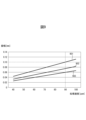
- FIG. 9 is a graph showing the relationship between the medium moving speed (processing speed) with respect to the surface 113a of the separation roller 113 and the amplitude A ss of the surface 113a of the separation roller 113. As shown in FIG.
- FIG. 9 The horizontal axis of FIG. 9 indicates the moving speed (processing speed) [ppm] of the medium with respect to the surface 113a of the separation roller 113, and the vertical axis indicates the amplitude A ss [mm] of vibration of the surface 113a of the separation roller 113.
- FIG. A graph 901 shows the amplitude A ss when the frequency f ss of the vibration of the surface 113a of the separation roller 113 is 3 kHz.
- Graph 902 shows the amplitude A ss when the frequency f ss is 4 kHz.
- Graph 903 shows the amplitude A ss when the frequency f ss is 5 kHz.
- the moving speed (processing speed) of the medium in the medium feeding device is 90 ppm or less. Therefore, as shown in FIG. 9, the amplitude A ss of the surface 113a of the separation roller 113 is 0.10 mm or less when the frequency f ss of vibration of the surface 113a of the separation roller 113 is 3 kHz or more and 5 kHz or less. .
- the medium feeding device 100 prevents sound generated by vibration of the surface 113a of the separation roller 113 from propagating on the surface 113a. It is possible to block (reduce) the noise.
- the width L5 (see FIG. 5B) of the plurality of flat portions 113c respectively arranged between the plurality of grooves 113b is , 1.0 mm or more.
- the diameter d of the opening 113d is too large, the media are not well separated.
- a media feeding experiment was conducted using a plurality of separation rollers each having a flat portion width of 1.0 mm and openings having different diameters. As a result, when the diameter of the opening was 0.35 mm or less, the media were well separated, but when the diameter of the opening was greater than 0.35 mm, the media were not separated. Therefore, the diameter d of the plurality of openings 113d is preferably 0.35 mm or less.
- the diameter d of the plurality of openings 113d is set to 0.10 mm or more and 0.35 mm or less. As a result, the medium feeding device 100 can suppress the generation of squeaking noise while separating the medium satisfactorily.
- the depth H of the plurality of openings 113d is preferably 0.2 mm or more so that the openings 113d remain even when the surface 113a of the separation roller 113 is worn.
- the separation roller is generally formed as an annular elastic body around a shaft that is a rotation axis.
- the annular elastic body includes two layers, an outer layer made of a non-foamed layer and an inner layer made of a foamed layer.
- the thickness (depth) of the outer layer is generally set to 1.0 mm or more and 1.5 mm or less.
- the depth H of the plurality of openings 113d is preferably 1.0 mm or less so that the plurality of openings 113d are formed in the outer layer of the separation roller 113 .
- the depth H of the plurality of openings 113d is set to 0.2 mm or more and 1.0 mm or less.
- the medium feeding device 100 can form the opening 113d only in the outer layer of the separation roller 113, and can continue to hold the opening 113d even when the surface 113a is worn.
- the contact area ratio P of the surface 113a of the separation roller 113 is set to 0.4 or more.
- the contact area ratio P of the separation roller 113 is calculated by the following formula (8).
- Contact area ratio P ⁇ (Surface area of surface 113a of separation roller 113 in nip region N ⁇ Area of groove 113b of separation roller 113 in nip region N ⁇ Total area of opening 113d of separation roller 113 in nip region N) ⁇ / (Surface area of surface 113a of separation roller 113 in nip region N) (8)
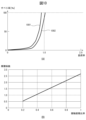
- FIG. 10(A), (B) and 11 are graphs for explaining the contact area ratio P of the separation roller 113.
- FIG. 10(A), (B) and 11 are graphs for explaining the contact area ratio P of the separation roller 113.
- FIG. 10A is a graph showing the relationship between the load factor applied to the medium fed by the feed roller 112 and the separation roller 113 and the slip ratio between the feed roller 112 and the medium.
- the horizontal axis of FIG. 10A indicates the load factor applied to the medium fed by the feeding roller 112 and separation roller 113, and the vertical axis indicates the slip ratio between the feeding roller 112 and the medium.
- a graph 1001 shows the slip ratio when the contact area ratio P of the separation roller 113 is 0.37
- a graph 1002 shows the slip ratio when the contact area ratio P of the separation roller 113 is 0.40.
- a load factor ⁇ applied to the medium fed by the feed roller 112 and the separation roller 113 is calculated by the following equation (9).
- ⁇ F/W (9)
- W is the force with which the pressing member 119 presses the separation roller 113 toward the feeding roller 112 side.
- F is the force exerted by the pressing force W on the medium being fed in the direction opposite to the medium conveying direction A1.
- a slip ratio R between the feed roller 112 and the medium is calculated by the following equation (10).
- R ⁇ (V r ⁇ V p )/V r ⁇ 100 (10)
- V r is the peripheral velocity of the feeding roller 112 (moving speed of the surface 112a of the feeding roller 112).
- V p is the velocity of movement of the surface of the medium.
- the load factor ⁇ when the slip ratio is 100% is the coefficient of friction between the feeding roller 112 and the medium, and the friction between the separation roller 113 and the medium. indicates the coefficient. That is, as shown in graph 1001, the coefficient of friction between the separation roller 113 and the medium is approximately 0.9 when the contact area ratio P of the separation roller 113 is 0.37. Further, as shown in graph 1002, the coefficient of friction between the separation roller 113 and the medium is approximately 1.0 when the contact area ratio P of the separation roller 113 is 0.40.
- the limit value of this torque limiter is set to such a value that the torque via the torque limiter is cut off when there is one medium, and the torque via the torque limiter is transmitted when there are a plurality of mediums.
- the separation roller 113 follows the feeding roller 112 without rotating according to the driving force from the motor.
- the separating roller 113 rotates or stops in the direction opposite to the medium feeding direction, and separates the medium in contact with the feeding roller 112 from the other media, thereby stacking them. to prevent transmission from occurring.
- the separation roller 113 follows the feeding roller 112, so that only a specific region continues to face the feeding roller 112, and wear can be suppressed.
- the coefficient of friction between the separation roller 113 and the medium must have a value of 1.0 or more, so the contact area ratio P of the separation roller 113 is It should be 0.40 or more.
- FIG. 10B is a graph showing the relationship between the contact area ratio P of the separation roller 113 and the coefficient of friction between the separation roller 113 and the medium.
- the horizontal axis of FIG. 10B indicates the contact area ratio P of the separation roller 113
- the vertical axis indicates the coefficient of friction between the separation roller 113 and the medium.
- the contact area ratio P of the separation roller 113 is preferably 0.40 or more.
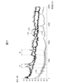
- FIG. 11 is a graph showing the relationship between frequency and sound pressure of sounds generated around the separation roller 113 .
- the horizontal axis of FIG. 11 indicates frequency, and the vertical axis indicates sound pressure.
- a graph 1101 shows a graph when the medium is fed by the separation roller whose contact area ratio S is 0.70.
- a graph 1102 shows a graph when the medium is fed by the separation roller whose contact area ratio S is 0.65.
- a graph 1103 shows a graph when the medium is fed by the separation roller whose contact area ratio S is 0.60.
- Graph 1104 shows the graph when no media is being fed.
- the separation roller As shown in graphs 1101 and 1102, with the separation roller having the contact area ratio S of 0.70 or 0.65, the frequency band R1 of 3 kHz to 4 kHz and its harmonic overtones of 6.5 kHz to 8 kHz are used during medium feeding. A loud abnormal noise (crying noise) is generated in the band R2.
- the separation roller with the contact area ratio S of 0.60 does not generate a loud noise (squeal) in the frequency bands R1 and R2 during medium feeding. That is, by setting the contact area ratio P of the separation roller 113 to 0.60 or less, the medium feeding device 100 can suppress the generation of squeaking noise.
- the opening 113d of the separation roller 113 is preferably set so that the contact area ratio P of the separation roller 113 is 0.4 or more and 0.6 or less.
- the medium feeding device 100 can suppress the generation of squeaking noise while suppressing wear of the separation roller 113 during medium feeding.
- the medium feeding device 100 can more effectively suppress the generation of squeaks.
- the contact area ratio P of the surface 113a of the separation roller 113 is preferably set to 0.5 or more.
- the medium feeding device 100 can reduce the frequency of occurrence of medium slippage during medium separation.
- the opening 113d may be omitted from the surface 113a of the separation roller 113.
- the contact area ratio P of the separation roller 113 is defined by the following formula (12) from the formula (11), and the pitch L3 of the grooves 113b of the separation roller 113 is determined by the following formula (13) from the formula (12).
- Pitch L3 of groove 113b of separation roller 113 (width L4 of groove 113b of separation roller 113)/(1-contact area ratio P) (13)
- the minimum width L4 of the groove 113b of the separation roller 113 is 0.5 mm and the minimum contact area ratio P is 0.5
- the minimum pitch L3 of the groove 113b of the separation roller 113 is 1.5 mm. 0 mm. Therefore, the pitch L3 of the plurality of grooves 113b of the separation roller 113 is 1.0 mm or more.
- the separation roller 113 can efficiently keep the foreign matter adhering to the fed medium in the groove 113b, and can continue to separate the medium satisfactorily for a long period of time from the initial state.
- the width L4 of the groove 113b of the separation roller 113 may be set to 2.0 mm or less.
- the fiber length of 95% or more of hardwood pulp used as paper is 2.0 mm or less
- the fiber length of 50% or more of softwood pulp used as paper is 2.0 mm or less. Therefore, by setting the width L4 of the groove 113b of the separation roller 113 to 2.0 mm, the medium feeding device 100 can accommodate most of the hardwood pulp and softwood pulp fibers in the groove 112b of the feeding roller 112. can be done.
- the pitch L3 of the grooves 113b of the separation roller 113 may be set to 4.0 mm or less.
- FIG. 12 is a block diagram showing a schematic configuration of the medium feeding device 100. As shown in FIG. 12
- the medium feeding device 100 further has a motor 131, an interface device 132, a storage device 140, a processing circuit 150, etc. in addition to the above configuration.
- the motor 131 has one or more motors, and rotates the feed roller 112, the separation roller 113, the first transport roller 114, and/or the second transport roller 117 in response to a control signal from the processing circuit 150 to feed the medium. be transported.
- the first opposing roller 115 and/or the second opposing roller 118 may be provided so as to rotate according to the driving force of the motor 131 instead of being driven to rotate by the first conveying roller 114 or the second conveying roller 117. .
- the interface device 132 has an interface circuit conforming to a serial bus such as USB, for example, and is electrically connected to an information processing device (for example, personal computer, personal digital assistant, etc.) (not shown) to receive an input image and various information. Send and receive.
- an information processing device for example, personal computer, personal digital assistant, etc.
- a communication unit having an antenna for transmitting and receiving wireless signals and a wireless communication interface device for transmitting and receiving signals through a wireless communication line according to a predetermined communication protocol may be used.
- the predetermined communication protocol is, for example, a wireless LAN (Local Area Network).
- the communication unit may have a wired communication interface device for transmitting and receiving signals through a wired communication line according to a communication protocol such as a wired LAN.
- the storage device 140 includes memory devices such as RAM (Random Access Memory) and ROM (Read Only Memory), fixed disk devices such as hard disks, or portable storage devices such as flexible disks and optical disks.
- the storage device 140 also stores computer programs, databases, tables, and the like used for various processes of the medium feeding device 100 .
- the computer program may be installed in the storage device 140 from a computer-readable portable recording medium using a known setup program or the like.
- Portable recording media are, for example, CD-ROMs (compact disc read only memory), DVD-ROMs (digital versatile disc read only memory), and the like.
- the processing circuit 150 operates based on a program stored in the storage device 140 in advance.
- the processing circuit is, for example, a CPU (Central Processing Unit).
- a DSP digital signal processor
- LSI large scale integration
- ASIC Application Specific Integrated Circuit
- FPGA Field-Programmable Gate Array
- the processing circuit 150 is connected to the operation device 105, the display device 106, the medium sensor 111, the imaging device 116, the motor 131, the interface device 132, the storage device 140, etc., and controls these units. Based on the medium signal received from the medium sensor 111, the processing circuit 150 performs drive control of the motor 131, imaging control of the imaging device 116, and the like. The processing circuit 150 acquires an input image from the imaging device 116 and transmits it to the information processing device via the interface device 132 .
- FIG. 13 is a diagram showing a schematic configuration of the storage device 140 and the processing circuit 150. As shown in FIG. 13
- the storage device 140 stores a control program 141, an image acquisition program 142, and the like. Each of these programs is a functional module implemented by software running on a processor.
- the processing circuit 150 reads each program stored in the storage device 140 and operates according to each read program. Thereby, the processing circuit 150 functions as a control section 151 and an image acquisition section 152 .
- FIG. 14 is a flow chart showing an example of the operation of the medium reading process of the medium feeding device 100.
- control unit 151 receives an instruction to read a medium from the operation device 105 or the interface device 132 when a user inputs an instruction to read the medium using the operation device 105 or the information processing device. (step S101).
- control unit 151 acquires a medium signal from the medium sensor 111, and determines whether or not a medium is placed on the placing table 103 based on the acquired medium signal (step S102). If no medium is placed on the placing table 103, the control unit 151 terminates the series of steps.
- control unit 151 drives the motor 131 to rotate the feeding roller 112 , the separating roller 113 , the first conveying roller 114 and/or the second conveying roller 117 . Rotate (step S103). Accordingly, the control unit 151 causes each roller to feed and convey the medium.
- control unit 151 causes the imaging device 116 to image a medium, acquires an input image from the imaging device 116, and outputs the acquired input image by transmitting it to the information processing device via the interface device 132. (Step S104).
- control unit 151 determines whether or not the medium remains on the mounting table 103 (step S105). When the medium remains on the mounting table 103, the control unit 151 returns the process to step S104 and repeats the processes of steps S104 and S105.
- control unit 151 controls the motor 131 to stop the feeding roller 112, the separating roller 113, the first conveying roller 114 and/or the second conveying roller 117. (step S106). Then, the control unit 151 ends the series of steps.
- the groove 112b is formed in the feeding roller 112 so that foreign matter can be well accommodated while suppressing the occurrence of medium slip. As a result, the medium feeding device 100 can feed the medium more satisfactorily.
- the groove 113b and the opening 113d are formed in the separation roller 113 so that the separation roller 113 can be prevented from being worn and squeaking noise can be suppressed.
- the medium feeding device 100 can reduce the replacement frequency of parts and improve usability, and as a result, it is possible to improve user convenience.
- the medium feeding device 100 suppresses the generation of squeaking noise by providing an opening 113d (concave portion) on the flat portion 113c instead of providing a protrusion on the surface 113a of the separation roller 113 . Even if the separation roller 113 is worn, it takes a long time for the entire flat portion 113c to wear away and the opening 113d to disappear. It becomes possible to
- FIG. 15 is a schematic diagram for explaining the surface 213a of the separation roller 213 in the medium feeding device according to another embodiment.
- a separation roller 213 shown in FIG. 15 is used in place of the separation roller 113 of the medium feeding device 100 .
- Separation roller 213 has a configuration similar to that of separation roller 113 .
- a plurality of flat portions 213c arranged between the plurality of grooves 213b are formed with a plurality of openings 213d.
- the plurality of openings 213d are arranged in a zigzag pattern.
- the medium feeding device can feed the medium even when the plurality of openings 213d are arranged in a zigzag pattern.
- FIG. 16 is a diagram showing a schematic configuration of a processing circuit 350 in a medium feeding device according to still another embodiment.
- the processing circuit 350 is used in place of the processing circuit 150 of the medium feeding device 100 and performs medium reading processing and the like instead of the processing circuit 150 .
- the processing circuit 350 has a control circuit 351, an image acquisition circuit 352, and the like. Each of these units may be composed of an independent integrated circuit, microprocessor, firmware, or the like.
- the control circuit 351 is an example of a control section and has the same function as the control section 151.
- the control circuit 351 receives an operation signal from the operation device 105 or the interface device 132 and a medium signal from the medium sensor 111 .
- the control circuit 351 controls the motor 131 based on the received information.
- the image acquisition circuit 352 is an example of an image acquisition section and has the same function as the image acquisition section 152.
- the image acquisition circuit 352 acquires an input image from the imaging device 116 and outputs it to the interface device 132 .
- the medium feeding device can feed the medium more satisfactorily even when the processing circuit 350 is used.
- Appendix 2 The medium feeding device according to appendix 1, wherein the plurality of openings are arranged in a staggered pattern.
- Appendix 3 The medium feeding device according to appendix 1 or 2, wherein the diameters of the plurality of openings are 0.10 mm or more and 0.35 mm or less.
- Appendix 4 The medium feeding device according to any one of Appendices 1 to 3, wherein the depth of the plurality of openings is 0.2 mm or more and 1.0 mm or less.
- Appendix 5 The medium feeding device according to any one of Appendices 1 to 4, wherein a plurality of grooves arranged perpendicularly to the medium feeding direction are formed on the surface of the feeding roller.
- the pitch of the plurality of grooves of the feed roller is set such that there is always at least one groove within the nip area during media feeding;
- the width of the plurality of grooves of the feeding roller is set to 0.5 mm or more, and the contact area ratio S is set to 0.5 or more,
- the contact area ratio S is ⁇ (the surface area of the feeding roller in the nip region ⁇ the groove area of the feeding roller in the nip region) ⁇ /(the surface area of the feeding roller in the nip region).
Landscapes
- Engineering & Computer Science (AREA)
- Mechanical Engineering (AREA)
- Sheets, Magazines, And Separation Thereof (AREA)
- Delivering By Means Of Belts And Rollers (AREA)
Abstract
媒体をより良好に給送することが可能な媒体給送装置を提供する。媒体給送装置は、媒体を給送するための給送ローラと、樹脂で形成され、且つ、給送ローラに対向して配置された分離ローラと、給送ローラと分離ローラとが接する位置にニップ領域が形成されるように、給送ローラ及び分離ローラの一方を他方に対して押圧する押圧部と、を有し、給送ローラの表面には、媒体の給送方向に対して垂直に配置された複数の溝が形成され、複数の溝のピッチは、媒体給送中に、ニップ領域内に少なくとも1本の溝が常に存在するように設定され、複数の溝の幅は、0.5mm以上であり、且つ、接触面積比率Sが0.5以上となるように設定され、接触面積比率Sは、{(ニップ領域における給送ローラの表面積-ニップ領域における給送ローラの溝の面積)}/(ニップ領域における給送ローラの表面積)である。
Description
本開示は、媒体給送装置に関する。
一般に、スキャナ等の媒体給送装置は、給送ローラ及び分離ローラを用いて、媒体を分離しながら給送する。このような媒体給送装置で給送される媒体には、紙粉、填料、塗工剤(顔料)、パウダ等の異物が付着している場合がある。このような媒体が給送される場合、媒体の表面に付着した異物が給送ローラに付着して、給送ローラの表面の摩擦係数が低下し、給送性能が低下する可能性がある。そのため、近年、異物を収容可能な溝が形成された給送ローラが開発されている。
ゴム組成物からなり、ローラ表面に凹凸を設けた紙送りローラが開示されている(特許文献1を参照)。
媒体給送装置では、媒体をより良好に給送できることが求められている。
実施形態に係る媒体給送装置は、媒体をより良好に給送することを目的とする。
実施形態の一側面に係る媒体給送装置は、媒体を給送するための給送ローラと、樹脂で形成され、且つ、給送ローラに対向して配置された分離ローラと、給送ローラと分離ローラとが接する位置にニップ領域が形成されるように、給送ローラ及び分離ローラの一方を他方に対して押圧する押圧部と、を有し、給送ローラの表面には、媒体の給送方向に対して垂直に配置された複数の溝が形成され、複数の溝のピッチは、媒体給送中に、ニップ領域内に少なくとも1本の溝が常に存在するように設定され、複数の溝の幅は、0.5mm以上であり、且つ、接触面積比率Sが0.5以上となるように設定され、接触面積比率Sは、{(ニップ領域における給送ローラの表面積-ニップ領域における給送ローラの溝の面積)}/(ニップ領域における給送ローラの表面積)である。
本実施形態によれば、媒体給送装置は、媒体をより良好に給送することが可能となる。
本発明の目的及び効果は、特に請求項において指摘される構成要素及び組み合わせを用いることによって認識され且つ得られるだろう。前述の一般的な説明及び後述の詳細な説明の両方は、例示的及び説明的なものであり、特許請求の範囲に記載されている本発明を制限するものではない。
以下、本開示の一側面に係る媒体給送装置、制御方法及び制御プログラムについて図を参照しつつ説明する。但し、本発明の技術的範囲はそれらの実施の形態に限定されず、特許請求の範囲に記載された発明とその均等物に及ぶ点に留意されたい。
図1は、イメージスキャナとして構成された媒体給送装置100を示す斜視図である。媒体給送装置100は、原稿である媒体を給送及び搬送し、撮像する。媒体は、用紙、薄紙、厚紙、カード、冊子又は封筒等である。給送される媒体には、紙粉、用紙作成時に付着される填料、塗工紙に付着される塗工剤(顔料)、カラー印刷時に付着されるパウダ等の異物が付着している。媒体給送装置100は、ファクシミリ、複写機、プリンタ複合機(MFP、Multifunction Peripheral)等でもよい。なお、搬送される媒体は、原稿でなく印刷対象物等でもよく、媒体給送装置100はプリンタ等でもよい。
媒体給送装置100は、下側筐体101、上側筐体102、載置台103、排出台104、操作装置105及び表示装置106等を備える。図1において矢印A1は媒体搬送方向を示し、矢印A2は媒体搬送方向と直交する幅方向を示し、矢印A3は媒体搬送面と直交する高さ方向を示す。以下では、上流とは媒体搬送方向A1の上流のことをいい、下流とは媒体搬送方向A1の下流のことをいう。
上側筐体102は、媒体給送装置100の上面を覆う位置に配置され、媒体つまり時、媒体給送装置100内部の清掃時等に開閉可能なように、ヒンジにより下側筐体101に回転可能に係合している。
載置台103は、下側筐体101に係合し、給送及び搬送される媒体を載置する。排出台104は、上側筐体102に係合し、排出された媒体を載置する。なお、排出台104は、下側筐体101に係合してもよい。
操作装置105は、ボタン等の入力デバイス及び入力デバイスから信号を取得するインタフェース回路を有し、利用者による入力操作を受け付け、利用者の入力操作に応じた操作信号を出力する。表示装置106は、液晶、有機EL(Electro-Luminescence)等を含むディスプレイ及びディスプレイに画像データを出力するインタフェース回路を有し、画像データをディスプレイに表示する。
図2は、媒体給送装置100内部の搬送経路を説明するための図である。
媒体給送装置100内部の搬送経路は、媒体センサ111、給送ローラ112、分離ローラ113、第1搬送ローラ114、第1対向ローラ115、撮像装置116、第2搬送ローラ117及び第2対向ローラ118等を有している。
なお、給送ローラ112、分離ローラ113、第1搬送ローラ114、第1対向ローラ115、第2搬送ローラ117及び/又は第2対向ローラ118のそれぞれの数は一つに限定されず、複数でもよい。その場合、給送ローラ112、分離ローラ113、第1搬送ローラ114、第1対向ローラ115、第2搬送ローラ117及び/又は第2対向ローラ118は、それぞれ媒体搬送方向と直交する幅方向A2に間隔を空けて並べて配置される。
下側筐体101の上面は、媒体の搬送路の下側ガイド101aを形成し、上側筐体102の下面は、媒体の搬送路の上側ガイド102aを形成する。
媒体センサ111は、給送ローラ112及び分離ローラ113より上流側に配置される。媒体センサ111は、接触検出センサを有し、載置台103に媒体が載置されているか否かを検出する。媒体センサ111は、載置台103に媒体が載置されている状態と載置されていない状態とで信号値が変化する媒体信号を生成して出力する。なお、媒体センサ111は接触検知センサに限定されず、媒体センサ111として、光検知センサ等の、媒体の有無を検出可能な他の任意のセンサが使用されてもよい。
給送ローラ112は、下側筐体101に設けられ、載置台103に載置された媒体を下側から順に分離して給送する。給送ローラ112は、ゴムもしくはプラスチック等の樹脂又は鉄等の金属等で形成される。分離ローラ113は、いわゆるブレーキローラ又はリタードローラであり、上側筐体102に設けられ、給送ローラ112に対向して配置される。分離ローラ113は、媒体給送方向の反対方向に回転可能に又は停止可能に設けられる。分離ローラ113は、ゴムもしくはプラスチック等の樹脂又は鉄等の金属等で形成される。なお、給送ローラ112が上側筐体102に、分離ローラ113が下側筐体101に設けられ、給送ローラ112は、載置台103に載置された媒体を上側から順に給送してもよい。
第1搬送ローラ114及び第1対向ローラ115は、媒体搬送方向A1において給送ローラ112及び分離ローラ113より下流側に配置される。第1搬送ローラ114は、上側筐体102に設けられ、給送ローラ112及び分離ローラ113によって給送された媒体を撮像装置116に搬送する。第1搬送ローラ114は、ゴムもしくはプラスチック等の樹脂又は鉄等の金属等で形成される。第1対向ローラ115は、下側筐体101に、第1搬送ローラ114の下側に第1搬送ローラ114に対向して設けられ、第1搬送ローラ114に従動して回転する。第1対向ローラ115は、ゴムもしくはプラスチック等の樹脂又は鉄等の金属等で形成される。なお、第1搬送ローラ114が下側筐体101に設けられ、第1対向ローラ115が上側筐体102に設けられてもよい。
撮像装置116は、撮像部の一例であり、媒体搬送方向A1において、第1搬送ローラ114及び第1対向ローラ115の下流側に配置され、第1搬送ローラ114及び第1対向ローラ115により搬送された媒体を撮像する。撮像装置116は、媒体搬送路を挟んで相互に対向して配置された第1撮像装置116a及び第2撮像装置116bを含む。
第1撮像装置116aは、主走査方向に直線状に配列されたCMOS(Complementary Metal Oxide Semiconductor)による撮像素子を有する等倍光学系タイプのCIS(Contact Image Sensor)によるラインセンサを有する。また、第1撮像装置116aは、撮像素子上に像を結ぶレンズと、撮像素子から出力された電気信号を増幅し、アナログ/デジタル(A/D)変換するA/D変換器とを有する。第1撮像装置116aは、後述する処理回路からの制御に従って、搬送される媒体の表面を撮像して入力画像を生成し、出力する。
同様に、第2撮像装置116bは、主走査方向に直線状に配列されたCMOSによる撮像素子を有する等倍光学系タイプのCISによるラインセンサを有する。また、第2撮像装置116bは、撮像素子上に像を結ぶレンズと、撮像素子から出力された電気信号を増幅し、アナログ/デジタル(A/D)変換するA/D変換器とを有する。第2撮像装置116bは、後述する処理回路からの制御に従って、搬送される媒体の裏面を撮像して入力画像を生成し、出力する。
なお、媒体給送装置100は、第1撮像装置116a及び第2撮像装置116bを一方だけ配置し、媒体の片面だけを読み取ってもよい。また、CMOSによる撮像素子を備える等倍光学系タイプのCISによるラインセンサの代わりに、CCD(Charge Coupled Device)による撮像素子を備える等倍光学系タイプのCISによるラインセンサが利用されてもよい。また、CMOS又はCCDによる撮像素子を備える縮小光学系タイプのラインセンサが利用されてもよい。
第2搬送ローラ117及び第2対向ローラ118は、媒体搬送方向A1において撮像装置116より、即ち給送ローラ112及び分離ローラ113より下流側に配置される。第2搬送ローラ117は、上側筐体102に設けられ、第1搬送ローラ114及び第1対向ローラ115によって搬送された媒体をさらに下流側に搬送し、排出台104に排出する。第2搬送ローラ117は、ゴムもしくはプラスチック等の樹脂又は鉄等の金属等で形成される。第2対向ローラ118は、下側筐体101に、第2搬送ローラ117の下側に第2搬送ローラ117に対向して設けられ、第2搬送ローラ117に従動して回転する。第2対向ローラ118は、ゴムもしくはプラスチック等の樹脂又は鉄等の金属等で形成される。なお、第2搬送ローラ117が下側筐体101に設けられ、第2対向ローラ118が上側筐体102に設けられてもよい。
載置台103に載置された媒体は、給送ローラ112が矢印A4の方向、即ち媒体給送方向に回転することによって、下側ガイド101aと上側ガイド102aの間を媒体搬送方向A1に向かって搬送される。分離ローラ113は、矢印A5の方向、即ち媒体給送方向の反対方向に回転又は停止する。給送ローラ112及び分離ローラ113の働きにより、載置台103に複数の媒体が載置されている場合、載置台103に載置されている媒体のうち給送ローラ112と接触している媒体のみが分離される。これにより、分離された媒体以外の媒体の搬送が制限される(重送の防止)。
媒体は、下側ガイド101aと上側ガイド102aによりガイドされながら、第1搬送ローラ114と第1対向ローラ115の間に送り込まれる。媒体は、第1搬送ローラ114が矢印A6の方向に回転することによって、第1撮像装置116aと第2撮像装置116bの間に送り込まれる。撮像装置116により読み取られた媒体は、第2搬送ローラ117が矢印A7の方向に回転することによって排出台104上に排出される。
図3は、給送ローラ112及び分離ローラ113に加えられる力について説明するための模式図である。
図3に示すように、媒体給送装置100は、押圧部材119をさらに有する。
押圧部材119は、押圧部の一例であり、一端が上側筐体102に、他端が分離ローラ113の回転軸であるシャフトに設けられ、分離ローラ113を給送ローラ112側に押圧する。押圧部材119は、ねじりコイルばね等の弾性部材を含み、分離ローラ113を給送ローラ112側に押圧する押圧力Wを発生させる。押圧部材119により、給送ローラ112と分離ローラ113とが接する位置にニップ領域が形成される。なお、押圧部材119は、板ばね等の他のばね部材、又は、ゴム部材等を含んでもよい。また、押圧部材119は、給送ローラ112を分離ローラ113側に押圧するように設けられてもよい。このように、押圧部材119は、給送ローラ112と分離ローラ113とが接する位置にニップ領域が形成されるように、給送ローラ112及び分離ローラ113の一方を他方に対して押圧する。
図4は、給送ローラ112及び分離ローラ113の表面について説明するための模式図である。図4は、給送ローラ112及び分離ローラ113を下流側から見た斜視図である。
図4に示すように、給送ローラ112の表面112aには、媒体搬送方向と直交する幅方向A2に、即ち媒体の給送方向に対して垂直に(給送ローラ112の回転軸であるシャフトと平行に)配置された複数の溝112bが形成される。即ち、複数の溝112bは、それぞれ媒体の給送方向と直交する方向に延伸するように、媒体の給送方向に相互に間隔を空けて並べて配置される。なお、媒体の給送方向に対して垂直とは、媒体の給送方向となす角度が90°であることに限定されず、媒体の給送方向となす角度が90°に対して所定角度(例えば±5°の範囲内の角度)傾いていることも含む。給送ローラ112の表面112aに媒体の給送方向に対して垂直に溝112bが配置されることにより、給送ローラ112は、媒体に付着している異物をより効率良く剥離する(削り取る)ことが可能となり、異物をより効率良く溝112bに収容することができる。
また、分離ローラ113の表面113aには、媒体搬送方向A1に、即ち媒体の給送方向に対して平行に(分離ローラ113の回転軸であるシャフトに対して垂直に)配置された複数の溝113bが形成される。即ち、複数の溝113bは、それぞれ媒体の給送方向に延伸するように、媒体の給送方向と直交する方向に相互に間隔を空けて並べて配置される。なお、媒体の給送方向に対して平行とは、媒体の給送方向となす角度が0°であることに限定されず、媒体の給送方向となす角度が0°に対して所定角度(例えば±5°の範囲内の角度)傾いていることも含む。分離ローラ113の表面113aに溝113bが配置されることにより、分離ローラ113によって媒体が押し戻される力が大きくなり、媒体給送装置100は、媒体の重送の発生を抑制できる。特に、分離ローラ113の表面113aに媒体の給送方向に対して平行に溝113bが配置されることにより、分離ローラ113の回転時に、ニップ領域Nにおける溝113bの位置が変化せず、分離力が一定に保たれる。これにより、媒体給送装置100は、媒体の重送の発生を抑制できる。
また、給送ローラ112の溝112bの延伸方向と、分離ローラ113の溝113bの延伸方向とが異なることにより、溝112b及び溝113bが干渉しあって分離ローラ113がバウンド(振動)することが抑制される。これにより、媒体給送装置100は、媒体の重送の発生を抑制できる。
また、給送ローラ112の溝112bの延伸方向と、分離ローラ113の溝113bの延伸方向とが相互に直交することにより、媒体からほつれて様々な方向に延伸する異物は、高い確率で、何れかの溝に収容される。
図5(A)は、給送ローラ112の溝112bについて説明するための模式図である。図5(A)は、給送ローラ112と分離ローラ113のニップ領域の周辺を側方から見た模式図である。
図5(A)に示すように、給送ローラ112の表面112aにおいて、複数の溝112bは、円周方向に沿って一定のピッチL1毎に形成される。複数の溝112bのピッチL1は、媒体給送中に、ニップ領域N内に少なくとも1本の溝112bが常に存在するように設定される。また、給送ローラ112の各溝112bの幅L2は、0.5mm以上となるように設定される。
ユーザの使用環境で媒体のスリップが発生するようになり返却されたローラ、及び、加速試験により媒体のスリップが発生するようになったローラを観測した結果、ローラに付着していた紙の繊維の固まりの90%以上が0.5mm以下であった。即ち、媒体給送時において、用紙等の媒体に含まれる繊維全体が剥離する可能性は低く、繊維の一部がほつれて媒体の表面に浮き上がり、ローラに擦れて剥離する可能性が高いことがわかった。媒体給送装置100は、給送ローラ112の溝112bの幅L2を0.5mm以上となるように設定することにより、給送ローラ112の表面112aに付着した繊維を効率良く溝112bに収容できる。これにより、媒体給送装置100は、給送ローラ112の表面112aに繊維が付着して給送ローラ112の表面112aと媒体の間の摩擦係数が低減し、媒体のスリップが発生することを抑制できる。したがって、媒体給送装置100は、媒体のジャムの発生を抑制できる。
図5(B)は、分離ローラ113の溝113bについて説明するための模式図である。図5(B)は、給送ローラ112と分離ローラ113のニップ領域の周辺を下流側から見た模式図である。
図5(B)に示すように、分離ローラ113の表面113aにおいて、複数の溝113bは、幅方向A2に沿って一定のピッチL3毎に形成される。また、分離ローラ113の各溝113bの幅L4は、0.5mm以上となるように設定される。
上記したように、媒体のスリップが発生するようになったローラを観測した結果、ローラに付着していた紙の繊維の固まりの90%以上が0.5mm以下であった。媒体給送装置100は、分離ローラ113の溝113bの幅L4を0.5mm以上となるように設定することにより、分離ローラ113の表面113aに付着した繊維を効率良く溝113bに収容できる。これにより、媒体給送装置100は、分離ローラ113の表面113aに繊維が付着して分離ローラ113の表面113aと媒体の間の摩擦係数が低減して媒体のスリップが発生することを抑制できる。したがって、媒体給送装置100は、媒体のジャムの発生を抑制できる。
また、給送ローラ112の表面112aにおいて、接触面積比率Sは、0.5以上となるように設定される。給送ローラ112の接触面積比率Sは、以下の式(1)により算出される。
接触面積比率S={(ニップ領域Nにおける給送ローラ112の表面112aの表面積-ニップ領域Nにおける給送ローラ112の溝112bの面積)}/(ニップ領域Nにおける給送ローラ112の表面112aの表面積) (1)
接触面積比率S={(ニップ領域Nにおける給送ローラ112の表面112aの表面積-ニップ領域Nにおける給送ローラ112の溝112bの面積)}/(ニップ領域Nにおける給送ローラ112の表面112aの表面積) (1)
図6(A)、(B)及び図7は、給送ローラ112の接触面積比率Sについて説明するためのグラフである。
図6(A)は、給送ローラにより給送された媒体の数と、その数の媒体を給送した給送ローラと媒体の間の摩擦係数との関係を示すグラフである。図6(A)の横軸は給送ローラにより給送された媒体の数を示し、縦軸はその数の媒体を給送した給送ローラと媒体の間の摩擦係数を示す。この給送ローラは、初期状態(まだ媒体を給送していない状態)において、溝を有しておらず且つ媒体との間の摩擦係数が約3.0であるローラである。図6(A)に示すように、給送した媒体の数が増大するほど、給送ローラと媒体の間の摩擦係数は低減し、媒体のスリップが発生する可能性が増大する。特に、異物が付着した媒体を大量に給送する加速試験を行った結果、摩擦係数が1.4未満になった場合に、媒体のスリップが発生する頻度が急激に増大することがわかった。
なお、二つの物体の間の最大静摩擦力は、せん断強さ(物体の材料が同一である場合は定数)と、二つの物体が実際に接触している面積との積で算出される。即ち、二つの物体の間の摩擦力は、接触面積に比例する。
図6(B)は、溝を有する給送ローラの接触面積比率Sと、給送ローラと媒体の間の摩擦係数との関係を示すグラフである。図6(B)の横軸は給送ローラの接触面積比率Sを示し、縦軸は給送ローラと媒体の間の摩擦係数を示す。図6(B)に示すように、接触面積比率Sと摩擦係数の間には、比例関係が成立している。上記したように、摩擦係数が1.4未満である場合、媒体のスリップが発生する頻度が高いため、摩擦係数は、1.4以上であることが好ましい。接触面積比率Sと摩擦係数の間には比例関係が成立しているため、接触面積比率Sは、媒体のスリップが発生する頻度が高くなる摩擦係数の閾値(1.4)を初期値(3.0)で除算した値(1.4/3.0≒0.5)以上であることが好ましい。給送ローラ112の接触面積比率Sが0.5以上に設定されることにより、媒体給送装置100は、媒体の給送時に媒体のスリップが発生する頻度を低減させることが可能となる。
図7は、異物が付着した媒体を大量に給送する加速試験における、給送ローラにより給送された媒体の数と、その数の媒体を給送した給送ローラによる媒体の給送力(フィード力)との関係を示すグラフである。図7の横軸は給送ローラにより給送された媒体の数を示し、縦軸はその数の媒体を給送した給送ローラによる媒体の給送力を示す。給送ローラ112による媒体の給送力は、給送ローラ112により給送される媒体に媒体給送方向にかかる力であり、給送ローラ112により給送される媒体の上流側の端部にテンションゲージを取り付けることにより測定される。
グラフ701は、接触面積比率Sが0.35である給送ローラについてのグラフを示す。グラフ702は、接触面積比率Sが0.50である給送ローラについてのグラフを示す。グラフ703は、接触面積比率Sが0.60である給送ローラについてのグラフを示す。グラフ704は、接触面積比率Sが0.90である給送ローラについてのグラフを示す。グラフ705は、接触面積比率Sが0.95である給送ローラについてのグラフを示す。
媒体を適切に給送させるためには、給送力として200[gf]以上の力が必要であった。グラフ701に示すように、接触面積比率Sが0.35である給送ローラは、初期状態(まだ媒体を給送していない状態)では、十分な給送力を発生させ、媒体を良好に給送することができた。しかしながら、この給送ローラでは、媒体を給送させるたびに給送力が急激に低減し、200枚程度の媒体を給送したときに、給送力が200[gf]未満となって、媒体を適切に給送できなくなった。また、グラフ702、703、704に示すように、接触面積比率Sが0.50、0.60又は0.80である給送ローラは、初期状態及び1000以上の媒体を給送した状態において、十分な給送力を発生させ、媒体を良好に給送することができた。一方、グラフ705に示すように、接触面積比率Sが0.95である給送ローラは、初期状態において、既に十分な給送力を発生することができず、媒体を適切に給送することができなかった。
したがって、上記したように、接触面積比率Sが0.5以上に設定されることにより、給送ローラ112は、長期間にわたって媒体を良好に給送することが可能となる。また、接触面積比率Sは、0.9以下となるように設定されることが好ましい。これにより、給送ローラ112は、初期状態から長期間にわたって媒体を良好に給送し続けることが可能となる。
また、給送ローラ112の接触面積比率Sは、式(1)から以下の式(2)のように規定され、給送ローラ112の溝112bのピッチL1は、式(2)から以下の式(3)のように規定される。
接触面積比率S={(給送ローラ112の溝112bのピッチL1-給送ローラ112の溝112bの幅L2)}/(給送ローラ112の溝112bの幅L2) (2)
給送ローラ112の溝112bのピッチL1=(給送ローラ112の溝112bの幅L2)/(1-接触面積比率S) (3)
接触面積比率S={(給送ローラ112の溝112bのピッチL1-給送ローラ112の溝112bの幅L2)}/(給送ローラ112の溝112bの幅L2) (2)
給送ローラ112の溝112bのピッチL1=(給送ローラ112の溝112bの幅L2)/(1-接触面積比率S) (3)
給送ローラ112の溝112bの幅L2の最小値が0.5mmであり、接触面積比率Sの最小値が0.5であるため、式(3)から、給送ローラ112の溝112bのピッチL1の最小値は、1.0mmである。また、一般に、給送ローラと分離ローラのニップ領域の幅は、4.0mm以上且つ6.0mm以下の範囲に設定される。給送ローラ112の溝112bのピッチL1は、媒体給送中に、ニップ領域N内に少なくとも1本の溝112bが常に存在するように設定されるため、ピッチL1の最大値は、4.0mmである。したがって、給送ローラ112の複数の溝112bのピッチL1は、1.0mm以上且つ4.0mm以下である。
給送ローラ112の溝112bの幅L2は、式(3)から以下の式(4)のように規定される。
給送ローラ112の溝112bの幅L2=(給送ローラ112の溝112bのピッチL1)×(1-接触面積比率S) (4)
給送ローラ112の溝112bの幅L2=(給送ローラ112の溝112bのピッチL1)×(1-接触面積比率S) (4)
給送ローラ112の溝112bのピッチL1の最大値が4.0mmであり、接触面積比率Sの最小値が0.5であるため、式(4)から、給送ローラ112の溝112bの幅L2の最大値は、2.0mmである。したがって、給送ローラ112の溝112bの幅L2は、2.0mm以下である。なお、用紙として使用される広葉樹パルプの95%以上の繊維長は2.0mm以下であり、用紙として使用される針葉樹パルプの50%以上の繊維長は2.0mm以下である。したがって、給送ローラ112の溝112bの幅L2が2.0mmに設定されることにより、媒体給送装置100は、大半の広葉樹パルプ及び針葉樹パルプの繊維を給送ローラ112の溝112bに収容することができる。
これらにより、給送ローラ112は、給送される媒体に付着した異物を溝112bに効率良く収容しつつ、初期状態から長期間にわたって媒体を良好に給送し続けることが可能となる。
図8(A)、(B)、(C)は、分離ローラ113の表面113aについて説明するための模式図である。図8(A)は、分離ローラ113の表面113aを上方から見た模式図であり、図8(B)は、図8(A)のA-A’線断面図であり、図8(C)は、図8(A)のB-B’線断面図である。
図8(A)、(B)、(C)に示すように、分離ローラ113の表面113aには、複数の溝113bの間にそれぞれ配置された複数の平坦部113cが形成される。また、複数の平坦部113cには、それぞれ複数の開口部113dが形成される。各開口部113dは、平坦部113cの一部を半球状(ドーム状)にくり抜くことにより形成される。即ち、各開口部113dは、上方から見た場合に円状に形成される。なお、各開口部113dは、楕円状、矩形状、三角形状等、任意の形状に形成されてもよい。
媒体が給送される際、分離ローラ113による媒体の分離動作によって分離ローラ113の表面113aが振動することにより、分離ローラ113の周辺には、異音(いわゆる鳴き音、スリップスティック音)が発生する。鳴き音は、特定の周波数帯域(例えば3kHz~4kHz、6.5kHz~8kHz等)の音である。
分離ローラ113の表面113a上の振動系について、振動の周波数fssは、以下の式(5)で算出され、振動の振幅Assは、以下の式(6)で算出される。
fss=kv/{2(μs-μk)W} (5)
Ass=(μs-μk)W/k (6)
ここで、kは分離ローラ113の表面113aの剛性(ばね定数)である。vは分離ローラ113の表面113aに対して媒体が移動する移動速度である。μsは分離ローラ113の表面113aと媒体の間の静摩擦係数である。μkは分離ローラ113の表面113aと媒体の間の動摩擦係数である。Wは分離ローラ113の表面113aにかかる垂直荷重である。周波数fss及び振幅Assの算出については「中野健、前川覚、ソフトマテリアルと摩擦振動、第177回ゴム技術シンポジウム、日本ゴム協会、p1-10(2012)」を参照されたい。
fss=kv/{2(μs-μk)W} (5)
Ass=(μs-μk)W/k (6)
ここで、kは分離ローラ113の表面113aの剛性(ばね定数)である。vは分離ローラ113の表面113aに対して媒体が移動する移動速度である。μsは分離ローラ113の表面113aと媒体の間の静摩擦係数である。μkは分離ローラ113の表面113aと媒体の間の動摩擦係数である。Wは分離ローラ113の表面113aにかかる垂直荷重である。周波数fss及び振幅Assの算出については「中野健、前川覚、ソフトマテリアルと摩擦振動、第177回ゴム技術シンポジウム、日本ゴム協会、p1-10(2012)」を参照されたい。
式(5)、(6)から、振動の振幅Assは、以下の式(7)で算出される。
Ass=v/2fss (7)
式(7)に示すように、分離ローラ113の表面113aの振幅Assは、分離ローラ113の表面113aに対する媒体の移動速度vに比例する。
Ass=v/2fss (7)
式(7)に示すように、分離ローラ113の表面113aの振幅Assは、分離ローラ113の表面113aに対する媒体の移動速度vに比例する。
図9は、分離ローラ113の表面113aに対する媒体の移動速度(処理速度)と、分離ローラ113の表面113aの振幅Assとの間の関係を示すグラフである。
図9の横軸は分離ローラ113の表面113aに対する媒体の移動速度(処理速度)[ppm]を示し、縦軸は分離ローラ113の表面113aの振動における振幅Ass[mm]を示す。グラフ901は、分離ローラ113の表面113aの振動における周波数fssが3kHzである場合の振幅Assを示す。グラフ902は、周波数fssが4kHzである場合の振幅Assを示す。グラフ903は、周波数fssが5kHzである場合の振幅Assを示す。
一般に、媒体給送装置における媒体の移動速度(処理速度)は、90ppm以下である。そのため、図9に示すように、分離ローラ113の表面113aの振動における周波数fssが3kHz以上且つ5kHz以下である場合の、分離ローラ113の表面113aの振幅Assは、0.10mm以下である。媒体給送装置100は、複数の開口部113dの直径(最大幅)dを0.10mm以上とすることにより、分離ローラ113の表面113aの振動により発生する音が表面113a上を伝搬することを遮断(軽減)させることが可能となる。
また、一般に、媒体を良好に分離するために、分離ローラ113の表面113aにおいて、複数の溝113bの間にそれぞれ配置された複数の平坦部113cの幅L5(図5(b)を参照)は、1.0mm以上に設定される。それに対して、開口部113dの直径dが大きすぎると、媒体が良好に分離されない。平坦部の幅が1.0mmであり且つ開口部の直径がそれぞれ異なる複数の分離ローラを用いて、媒体を給送する実験を行った。その結果、開口部の直径が0.35mm以下である場合には媒体が良好に分離されたが、開口部の直径が0.35mmより大きい場合に媒体が分離されない事象が発生した。したがって、複数の開口部113dの直径dは、0.35mm以下であることが好ましい。
したがって、複数の開口部113dの直径dは、0.10mm以上且つ0.35mm以下に設定される。これにより、媒体給送装置100は、媒体を良好に分離しつつ、鳴き音の発生を抑制することが可能となる。
また、分離ローラ113の表面113aが摩耗した場合でも、開口部113dが存在するように、複数の開口部113dの深さHは0.2mm以上であることが好ましい。
また、一般に、分離ローラは、回転軸であるシャフトの周囲に、環状弾性体として形成される。環状弾性体は、非発泡層からなる外層と、発泡層からなる内層との二層を含んでいる。このような分離ローラにおいて、一般に、外層の厚さ(深さ)は、1.0mm以上且つ1.5mm以下に設定される。複数の開口部113dが分離ローラ113の外層に形成されるように、複数の開口部113dの深さHは1.0mm以下であることが好ましい。
したがって、複数の開口部113dの深さHは、0.2mm以上且つ1.0mm以下に設定される。これにより、媒体給送装置100は、分離ローラ113の外層にのみ開口部113dを形成しつつ、表面113aが摩耗した場合でも、開口部113dを保持し続けることが可能となる。
また、分離ローラ113の表面113aにおいて、接触面積比率Pは、0.4以上となるように設定される。分離ローラ113の接触面積比率Pは、以下の式(8)により算出される。
接触面積比率P={(ニップ領域Nにおける分離ローラ113の表面113aの表面積-ニップ領域Nにおける分離ローラ113の溝113bの面積-ニップ領域Nにおける分離ローラ113の開口部113dの総面積)}/(ニップ領域Nにおける分離ローラ113の表面113aの表面積) (8)
接触面積比率P={(ニップ領域Nにおける分離ローラ113の表面113aの表面積-ニップ領域Nにおける分離ローラ113の溝113bの面積-ニップ領域Nにおける分離ローラ113の開口部113dの総面積)}/(ニップ領域Nにおける分離ローラ113の表面113aの表面積) (8)
図10(A)、(B)及び図11は、分離ローラ113の接触面積比率Pについて説明するためのグラフである。
図10(A)は、給送ローラ112及び分離ローラ113により給送される媒体にかかる負荷率と、給送ローラ112と媒体の間のすべり率との関係を示すグラフである。図10(A)の横軸は給送ローラ112及び分離ローラ113により給送される媒体にかかる負荷率を示し、縦軸は給送ローラ112と媒体の間のすべり率を示す。グラフ1001は、分離ローラ113の接触面積比率Pが0.37である場合のすべり率を示し、グラフ1002は、分離ローラ113の接触面積比率Pが0.40である場合のすべり率を示す。
給送ローラ112及び分離ローラ113により給送される媒体にかかる負荷率ηは、以下の式(9)により算出される。
η=F/W (9)
ここで、Wは、押圧部材119により分離ローラ113を給送ローラ112側に押圧する力である。Fは、押圧力Wにより、給送される媒体に対して媒体搬送方向A1と反対側にかかる力である。
η=F/W (9)
ここで、Wは、押圧部材119により分離ローラ113を給送ローラ112側に押圧する力である。Fは、押圧力Wにより、給送される媒体に対して媒体搬送方向A1と反対側にかかる力である。
給送ローラ112と媒体の間のすべり率Rは、以下の式(10)により算出される。
R={(Vr-Vp)/Vr}×100 (10)
ここで、Vrは、給送ローラ112の周速度(給送ローラ112の表面112aの移動速度)である。Vpは、媒体の表面の移動速度である。
R={(Vr-Vp)/Vr}×100 (10)
ここで、Vrは、給送ローラ112の周速度(給送ローラ112の表面112aの移動速度)である。Vpは、媒体の表面の移動速度である。
すべり率が0%である場合、媒体は給送ローラ112に対してすべることなく給送され、すべり率が100%である場合、給送ローラ112が回転しているのにもかかわらず、媒体は停止している。すべり率が100%である場合の負荷率η、即ち媒体が停止している場合の負荷率ηは、給送ローラ112と媒体の間の摩擦係数、及び、分離ローラ113と媒体の間の摩擦係数を示す。即ち、グラフ1001に示すように、分離ローラ113の接触面積比率Pが0.37である場合の分離ローラ113と媒体の間の摩擦係数は約0.9である。また、グラフ1002に示すように、分離ローラ113の接触面積比率Pが0.40である場合の分離ローラ113と媒体の間の摩擦係数は約1.0である。
後述するモータからの駆動力は、トルクリミッタを介して分離ローラ113に伝達される。このトルクリミッタのリミット値は、媒体が一つの場合はトルクリミッタを介した回転力が絶たれ、媒体が複数の場合はトルクリミッタを介した回転力が伝達されるような値に設定される。これにより、媒体が一つだけ搬送される場合、分離ローラ113は、モータからの駆動力に従って回転することなく、給送ローラ112に従って従動する。一方、媒体が複数搬送される場合、分離ローラ113は、媒体給送方向の反対方向に回転又は停止し、給送ローラ112と接触している媒体とそれ以外の媒体とを分離して、重送の発生を防止する。分離ローラ113は、媒体が一つだけ搬送される場合に、給送ローラ112に従って従動することにより、特定の領域のみが給送ローラ112と対向し続けて、摩耗することを抑制できる。
但し、分離ローラ113が給送ローラ112に従って従動するためには、分離ローラ113と媒体の間の摩擦係数が1.0以上の値を有する必要があるため、分離ローラ113の接触面積比率Pが0.40以上である必要がある。
図10(B)は、分離ローラ113の接触面積比率Pと、分離ローラ113と媒体の間の摩擦係数との関係を示すグラフである。図10(B)の横軸は分離ローラ113の接触面積比率Pを示し、縦軸は分離ローラ113と媒体の間の摩擦係数を示す。図10(B)に示すように、接触面積比率Pと摩擦係数の間には、比例関係が成立している。上記したように、摩擦係数が1.0未満である場合、媒体が一つだけ搬送される場合に分離ローラ113が給送ローラ112に従って従動しないため、摩擦係数が1.0以上となるように、分離ローラ113の接触面積比率Pは0.40以上であることが好ましい。分離ローラ113の接触面積比率Pが0.40以上に設定されることにより、媒体給送装置100は、媒体の給送時に分離ローラ113の特定の領域のみが摩耗することを抑制できる。
図11は、分離ローラ113の周辺に発生する音について、周波数と音圧の関係を示すグラフである。図11の横軸は周波数を示し、縦軸は音圧を示す。グラフ1101は、接触面積比率Sが0.70である分離ローラによる媒体給送時のグラフを示す。グラフ1102は、接触面積比率Sが0.65である分離ローラによる媒体給送時のグラフを示す。グラフ1103は、接触面積比率Sが0.60である分離ローラによる媒体給送時のグラフを示す。グラフ1104は、媒体を給送していない時のグラフを示す。
グラフ1101、1102に示すように、接触面積比率Sが0.70又は0.65である分離ローラでは、媒体給送時に、3kHz~4kHzの周波数帯域R1及びその倍音の6.5kHz~8kHzの周波数帯域R2において大きい異音(鳴き音)が発生している。一方、グラフ1103に示すように、接触面積比率Sが0.60である分離ローラでは、媒体給送時に、周波数帯域R1、R2において大きい異音(鳴き音)が発生していない。即ち、分離ローラ113の接触面積比率Pが0.60以下に設定されることにより、媒体給送装置100は、鳴き音の発生を抑制できる。
したがって、分離ローラ113の開口部113dは、分離ローラ113の接触面積比率Pが0.4以上、且つ、0.6以下となるように設定されることが好ましい。これにより、媒体給送装置100は、媒体の給送時に分離ローラ113が摩耗することを抑制しつつ、鳴き音の発生を抑制できる。
なお、分離ローラ113の平坦部113cにおいて、ニップ領域N内の円周方向に沿った何れのライン内においても、二つ以上の開口部113dが配置されることが好ましい。これにより、媒体給送装置100は、より良好に鳴き音の発生を抑制できる。
また、給送ローラ112の表面112aと同様に、分離ローラ113の表面113aにおいて、接触面積比率Pは、0.5以上となるように設定されることが好ましい。分離ローラ113の接触面積比率Sが0.5以上に設定されることにより、媒体給送装置100は、媒体の分離時に媒体のスリップが発生する頻度を低減させることが可能となる。
また、分離ローラ113の表面113aにおいて、開口部113dは省略されてもよい。その場合、分離ローラ113の接触面積比率Pは、以下の式(11)により算出される。
接触面積比率P={(ニップ領域Nにおける分離ローラ113の表面113aの表面積-ニップ領域Nにおける分離ローラ113の溝113bの面積)}/(ニップ領域Nにおける分離ローラ113の表面113aの表面積) (11)
接触面積比率P={(ニップ領域Nにおける分離ローラ113の表面113aの表面積-ニップ領域Nにおける分離ローラ113の溝113bの面積)}/(ニップ領域Nにおける分離ローラ113の表面113aの表面積) (11)
また、分離ローラ113の接触面積比率Pは、式(11)から以下の式(12)のように規定され、分離ローラ113の溝113bのピッチL3は、式(12)から以下の式(13)のように規定される。
接触面積比率P={(分離ローラ113の溝113bのピッチL3-分離ローラ113の溝113bの幅L4)}/(分離ローラ113の溝113bの幅L4) (12)
分離ローラ113の溝113bのピッチL3=(分離ローラ113の溝113bの幅L4)/(1-接触面積比率P) (13)
接触面積比率P={(分離ローラ113の溝113bのピッチL3-分離ローラ113の溝113bの幅L4)}/(分離ローラ113の溝113bの幅L4) (12)
分離ローラ113の溝113bのピッチL3=(分離ローラ113の溝113bの幅L4)/(1-接触面積比率P) (13)
分離ローラ113の溝113bの幅L4の最小値が0.5mmであり、接触面積比率Pの最小値が0.5であるため、分離ローラ113の溝113bのピッチL3の最小値は、1.0mmである。したがって、分離ローラ113の複数の溝113bのピッチL3は、1.0mm以上である。
これにより、分離ローラ113は、給送される媒体に付着した異物を溝113bに効率良く収容しつつ、初期状態から長期間にわたって媒体を良好に分離し続けることが可能となる。
また、給送ローラ112の溝112bと同様に、分離ローラ113の溝113bの幅L4は、2.0mm以下に設定されてもよい。上記したように、用紙として使用される広葉樹パルプの95%以上の繊維長は2.0mm以下であり、用紙として使用される針葉樹パルプの50%以上の繊維長は2.0mm以下である。したがって、分離ローラ113の溝113bの幅L4が2.0mmに設定されることにより、媒体給送装置100は、大半の広葉樹パルプ及び針葉樹パルプの繊維を給送ローラ112の溝112bに収容することができる。また、給送ローラ112の溝112bと同様に、分離ローラ113の溝113bのピッチL3は、4.0mm以下に設定されてもよい。
図12は、媒体給送装置100の概略構成を示すブロック図である。
媒体給送装置100は、前述した構成に加えて、モータ131、インタフェース装置132、記憶装置140及び処理回路150等をさらに有する。
モータ131は、一又は複数のモータを有し、処理回路150からの制御信号によって、給送ローラ112、分離ローラ113、第1搬送ローラ114及び/又は第2搬送ローラ117を回転させて媒体を搬送させる。なお、第1対向ローラ115及び/又は第2対向ローラ118は、第1搬送ローラ114又は第2搬送ローラ117に従動回転するのでなく、モータ131の駆動力に従って回転するように設けられてもよい。
インタフェース装置132は、例えばUSB等のシリアルバスに準じるインタフェース回路を有し、不図示の情報処理装置(例えば、パーソナルコンピュータ、携帯情報端末等)と電気的に接続して入力画像及び各種の情報を送受信する。また、インタフェース装置132の代わりに、無線信号を送受信するアンテナと、所定の通信プロトコルに従って、無線通信回線を通じて信号の送受信を行うための無線通信インタフェース装置とを有する通信部が用いられてもよい。所定の通信プロトコルは、例えば無線LAN(Local Area Network)である。通信部は、有線LAN等の通信プロトコルに従って、有線通信回線を通じて信号の送受信を行うための有線通信インタフェース装置を有してもよい。
記憶装置140は、RAM(Random Access Memory)、ROM(Read Only Memory)等のメモリ装置、ハードディスク等の固定ディスク装置、又はフレキシブルディスク、光ディスク等の可搬用の記憶装置等を有する。また、記憶装置140には、媒体給送装置100の各種処理に用いられるコンピュータプログラム、データベース、テーブル等が格納される。コンピュータプログラムは、コンピュータ読み取り可能な可搬型記録媒体から、公知のセットアッププログラム等を用いて記憶装置140にインストールされてもよい。可搬型記録媒体は、例えばCD-ROM(compact disc read only memory)、DVD-ROM(digital versatile disc read only memory)等である。
処理回路150は、予め記憶装置140に記憶されているプログラムに基づいて動作する。処理回路は、例えばCPU(Central Processing Unit)である。処理回路150として、DSP(digital signal processor)、LSI(large scale integration)、ASIC(Application Specific Integrated Circuit)、FPGA(Field-Programmable Gate Array)等が用いられてもよい。
処理回路150は、操作装置105、表示装置106、媒体センサ111、撮像装置116、モータ131、インタフェース装置132及び記憶装置140等と接続され、これらの各部を制御する。処理回路150は、媒体センサ111から受信した媒体信号に基づいて、モータ131の駆動制御、撮像装置116の撮像制御等を行う。処理回路150は、撮像装置116から入力画像を取得し、インタフェース装置132を介して情報処理装置に送信する。
図13は、記憶装置140及び処理回路150の概略構成を示す図である。
図13に示すように、記憶装置140には、制御プログラム141及び画像取得プログラム142等が記憶される。これらの各プログラムは、プロセッサ上で動作するソフトウェアにより実装される機能モジュールである。処理回路150は、記憶装置140に記憶された各プログラムを読み取り、読み取った各プログラムに従って動作する。これにより、処理回路150は、制御部151及び画像取得部152として機能する。
図14は、媒体給送装置100の媒体読取処理の動作の例を示すフローチャートである。
以下、図14に示したフローチャートを参照しつつ、媒体給送装置100の媒体読取処理の動作の例を説明する。なお、以下に説明する動作のフローは、予め記憶装置140に記憶されているプログラムに基づき主に処理回路150により媒体給送装置100の各要素と協働して実行される。
最初に、制御部151は、利用者により操作装置105又は情報処理装置を用いて媒体の読み取りの指示が入力されて、媒体の読み取りを指示する操作信号を操作装置105又はインタフェース装置132から受信するまで待機する(ステップS101)。
次に、制御部151は、媒体センサ111から媒体信号を取得し、取得した媒体信号に基づいて、載置台103に媒体が載置されているか否かを判定する(ステップS102)。載置台103に媒体が載置されていない場合、制御部151は、一連のステップを終了する。
一方、載置台103に媒体が載置されている場合、制御部151は、モータ131を駆動して、給送ローラ112、分離ローラ113、第1搬送ローラ114及び/又は第2搬送ローラ117を回転させる(ステップS103)。これにより制御部151は、各ローラに媒体を給送及び搬送させる。
次に、制御部151は、撮像装置116に媒体を撮像させて、撮像装置116から入力画像を取得し、取得した入力画像を、インタフェース装置132を介して情報処理装置に送信することにより出力する(ステップS104)。
次に、制御部151は、媒体センサ111から受信する媒体信号に基づいて載置台103に媒体が残っているか否かを判定する(ステップS105)。載置台103に媒体が残っている場合、制御部151は、処理をステップS104へ戻し、ステップS104~S105の処理を繰り返す。
一方、載置台103に媒体が残っていない場合、制御部151は、給送ローラ112、分離ローラ113、第1搬送ローラ114及び/又は第2搬送ローラ117を停止させるように、モータ131を制御する(ステップS106)。そして、制御部151は、一連のステップを終了する。
以上詳述したように、媒体給送装置100では、給送ローラ112において、媒体のスリップの発生を抑制しつつ異物を良好に収容できるように溝112bが形成される。これにより、媒体給送装置100は、媒体をより良好に給送することが可能となった。
さらに、媒体給送装置100では、分離ローラ113において、分離ローラ113の摩耗の発生を抑制しつつ鳴き音の発生を抑制できるように溝113b及び開口部113dが形成される。これにより、媒体給送装置100は、部品の交換頻度を低減させるとともに、ユーザビリティを向上させることが可能となり、その結果、利用者の利便性を向上させることが可能となった。
特に、媒体給送装置100は、分離ローラ113の表面113a上に突起を設けるのでなく、平坦部113c上に開口部113d(凹部)を設けることにより、鳴き音の発生を抑制している。分離ローラ113が摩耗した場合であっても、平坦部113c全体がすり減って開口部113dがなくなるまでには多大な時間がかかるため、媒体給送装置100は、長期間にわたって鳴き音の発生を抑制することが可能となる。
図15は、他の実施形態に係る媒体給送装置における分離ローラ213の表面213aについて説明するための模式図である。
図15に示す分離ローラ213は、媒体給送装置100の分離ローラ113に代えて使用される。分離ローラ213は、分離ローラ113と同様の構成を有する。但し、分離ローラ213の表面213aにおいて、複数の溝213bの間にそれぞれ配置された複数の平坦部213cには、それぞれ複数の開口部213dが形成される。複数の開口部213dは、千鳥状に配置される。これにより、媒体給送装置は、分離ローラ213の表面213aにおいて、開口部213dを高密度に効率良く配置することが可能となり、鳴き音の発生をより抑制することが可能となる。
以上詳述したように、媒体給送装置は、複数の開口部213dが千鳥状に配置される場合も、媒体をより良好に給送することが可能となった。
図16は、さらに他の実施形態に係る媒体給送装置における処理回路350の概略構成を示す図である。処理回路350は、媒体給送装置100の処理回路150の代わりに使用され、処理回路150の代わりに、媒体読取処理等を実行する。処理回路350は、制御回路351及び画像取得回路352等を有する。なお、これらの各部は、それぞれ独立した集積回路、マイクロプロセッサ、ファームウェア等で構成されてもよい。
制御回路351は、制御部の一例であり、制御部151と同様の機能を有する。制御回路351は、操作装置105又はインタフェース装置132から操作信号を、媒体センサ111から媒体信号を受信する。制御回路351は、受信した各情報に基づいてモータ131を制御する。
画像取得回路352は、画像取得部の一例であり、画像取得部152と同様の機能を有する。画像取得回路352は、撮像装置116から入力画像を取得し、インタフェース装置132に出力する。
以上詳述したように、媒体給送装置は、処理回路350を用いる場合においても、媒体をより良好に給送することが可能となった。
上述した実施の形態に関し、さらに以下の付記を開示する。
(付記1)
媒体を給送するための給送ローラと、
樹脂で形成され、且つ、前記給送ローラに対向して配置された分離ローラと、
前記給送ローラと前記分離ローラとが接する位置にニップ領域が形成されるように、前記給送ローラ及び前記分離ローラの一方を他方に対して押圧する押圧部と、を有し、
前記分離ローラの表面には、媒体の給送方向に対して平行に配置された複数の溝と、前記複数の溝の間にそれぞれ配置された複数の平坦部が形成され、
前記複数の平坦部には、それぞれ複数の開口部が形成され、
前記開口部は、接触面積比率Pが0.4以上、且つ、0.6以下となるように設定され、
前記接触面積比率Pは、{(前記ニップ領域における前記分離ローラの表面積)-(前記ニップ領域における前記分離ローラの溝の面積-前記ニップ領域における前記分離ローラの開口部の総面積)}/(前記ニップ領域における前記分離ローラの表面積)である、
ことを特徴とする媒体給送装置。
媒体を給送するための給送ローラと、
樹脂で形成され、且つ、前記給送ローラに対向して配置された分離ローラと、
前記給送ローラと前記分離ローラとが接する位置にニップ領域が形成されるように、前記給送ローラ及び前記分離ローラの一方を他方に対して押圧する押圧部と、を有し、
前記分離ローラの表面には、媒体の給送方向に対して平行に配置された複数の溝と、前記複数の溝の間にそれぞれ配置された複数の平坦部が形成され、
前記複数の平坦部には、それぞれ複数の開口部が形成され、
前記開口部は、接触面積比率Pが0.4以上、且つ、0.6以下となるように設定され、
前記接触面積比率Pは、{(前記ニップ領域における前記分離ローラの表面積)-(前記ニップ領域における前記分離ローラの溝の面積-前記ニップ領域における前記分離ローラの開口部の総面積)}/(前記ニップ領域における前記分離ローラの表面積)である、
ことを特徴とする媒体給送装置。
(付記2)
前記複数の開口部は、千鳥状に配置される、付記1に記載の媒体給送装置。
前記複数の開口部は、千鳥状に配置される、付記1に記載の媒体給送装置。
(付記3)
前記複数の開口部の直径は、0.10mm以上且つ0.35mm以下である、付記1または2に記載の媒体給送装置。
前記複数の開口部の直径は、0.10mm以上且つ0.35mm以下である、付記1または2に記載の媒体給送装置。
(付記4)
前記複数の開口部の深さは、0.2mm以上且つ1.0mm以下である、付記1~3の何れか一項に記載の媒体給送装置。
前記複数の開口部の深さは、0.2mm以上且つ1.0mm以下である、付記1~3の何れか一項に記載の媒体給送装置。
(付記5)
前記給送ローラの表面には、媒体の給送方向に対して垂直に配置された複数の溝が形成される、付記1~4の何れか一項に記載の媒体給送装置。
前記給送ローラの表面には、媒体の給送方向に対して垂直に配置された複数の溝が形成される、付記1~4の何れか一項に記載の媒体給送装置。
(付記6)
前記給送ローラの複数の溝のピッチは、媒体給送中に、前記ニップ領域内に少なくとも1本の溝が常に存在するように設定され、
前記給送ローラの複数の溝の幅は、0.5mm以上であり、且つ、接触面積比率Sが0.5以上となるように設定され、
前記接触面積比率Sは、{(前記ニップ領域における前記給送ローラの表面積-前記ニップ領域における前記給送ローラの溝の面積)}/(前記ニップ領域における前記給送ローラの表面積)である、付記5に記載の媒体給送装置。
前記給送ローラの複数の溝のピッチは、媒体給送中に、前記ニップ領域内に少なくとも1本の溝が常に存在するように設定され、
前記給送ローラの複数の溝の幅は、0.5mm以上であり、且つ、接触面積比率Sが0.5以上となるように設定され、
前記接触面積比率Sは、{(前記ニップ領域における前記給送ローラの表面積-前記ニップ領域における前記給送ローラの溝の面積)}/(前記ニップ領域における前記給送ローラの表面積)である、付記5に記載の媒体給送装置。
100 媒体給送装置、112 給送ローラ、112a 表面、112b 溝、113 分離ローラ、113a 表面、113b 溝、119 押圧部材
Claims (5)
- 媒体を給送するための給送ローラと、
樹脂で形成され、且つ、前記給送ローラに対向して配置された分離ローラと、
前記給送ローラと前記分離ローラとが接する位置にニップ領域が形成されるように、前記給送ローラ及び前記分離ローラの一方を他方に対して押圧する押圧部と、を有し、
前記給送ローラの表面には、媒体の給送方向に対して垂直に配置された複数の溝が形成され、
前記複数の溝のピッチは、媒体給送中に、前記ニップ領域内に少なくとも1本の溝が常に存在するように設定され、
前記複数の溝の幅は、0.5mm以上であり、且つ、接触面積比率Sが0.5以上となるように設定され、
前記接触面積比率Sは、{(前記ニップ領域における前記給送ローラの表面積-前記ニップ領域における前記給送ローラの溝の面積)}/(前記ニップ領域における前記給送ローラの表面積)である、
ことを特徴とする媒体給送装置。 - 前記接触面積比率Sは、0.9以下となるように設定される、請求項1に記載の媒体給送装置。
- 前記分離ローラの表面には、媒体の給送方向に対して平行に配置された複数の溝が形成される、請求項1または2に記載の媒体給送装置。
- 前記分離ローラの複数の溝の幅は、0.5mm以上であり、且つ、接触面積比率Pが0.5以上となるように設定され、
前記接触面積比率Pは、{(前記ニップ領域における前記分離ローラの表面積-前記ニップ領域における前記分離ローラの溝の面積)}/(前記ニップ領域における前記分離ローラの表面積)である、請求項3に記載の媒体給送装置。 - 前記給送ローラの複数の溝の幅は、2.0mm以下であり、
前記給送ローラの複数の溝のピッチは、1.0mm以上且つ4.0mm以下である、請求項1~4の何れか一項に記載の媒体給送装置。
Priority Applications (4)
| Application Number | Priority Date | Filing Date | Title |
|---|---|---|---|
| PCT/JP2021/043697 WO2023095352A1 (ja) | 2021-11-29 | 2021-11-29 | 媒体給送装置 |
| JP2023563497A JP7606011B2 (ja) | 2021-11-29 | 2021-11-29 | 媒体給送装置 |
| US18/666,205 US20240300756A1 (en) | 2021-11-29 | 2024-05-16 | Media feeding apparatus |
| JP2024218164A JP7854491B2 (ja) | 2021-11-29 | 2024-12-12 | 媒体給送装置 |
Applications Claiming Priority (1)
| Application Number | Priority Date | Filing Date | Title |
|---|---|---|---|
| PCT/JP2021/043697 WO2023095352A1 (ja) | 2021-11-29 | 2021-11-29 | 媒体給送装置 |
Related Child Applications (1)
| Application Number | Title | Priority Date | Filing Date |
|---|---|---|---|
| US18/666,205 Continuation US20240300756A1 (en) | 2021-11-29 | 2024-05-16 | Media feeding apparatus |
Publications (1)
| Publication Number | Publication Date |
|---|---|
| WO2023095352A1 true WO2023095352A1 (ja) | 2023-06-01 |
Family
ID=86539088
Family Applications (1)
| Application Number | Title | Priority Date | Filing Date |
|---|---|---|---|
| PCT/JP2021/043697 Ceased WO2023095352A1 (ja) | 2021-11-29 | 2021-11-29 | 媒体給送装置 |
Country Status (3)
| Country | Link |
|---|---|
| US (1) | US20240300756A1 (ja) |
| JP (2) | JP7606011B2 (ja) |
| WO (1) | WO2023095352A1 (ja) |
Citations (2)
| Publication number | Priority date | Publication date | Assignee | Title |
|---|---|---|---|---|
| JPH0853251A (ja) * | 1994-08-08 | 1996-02-27 | Bridgestone Corp | 弾性体ロール |
| JP2019127363A (ja) * | 2018-01-24 | 2019-08-01 | キヤノン株式会社 | 給送回転体、シート給送装置及び画像形成装置 |
Family Cites Families (8)
| Publication number | Priority date | Publication date | Assignee | Title |
|---|---|---|---|---|
| JP3744319B2 (ja) | 2000-08-04 | 2006-02-08 | 東海ゴム工業株式会社 | 給紙ローラー |
| JP4936992B2 (ja) | 2007-05-23 | 2012-05-23 | 東海ゴム工業株式会社 | 紙送り用ロールの製法 |
| JP5506838B2 (ja) | 2012-02-16 | 2014-05-28 | 住友ゴム工業株式会社 | 紙送りローラの製造方法 |
| TWI566952B (zh) * | 2015-10-06 | 2017-01-21 | 虹光精密工業股份有限公司 | 傳輸輪以及包含其之傳動組件及事務機 |
| JP6114800B1 (ja) * | 2015-10-23 | 2017-04-12 | 株式会社Pfu | 給送ローラ |
| JP6667357B2 (ja) | 2016-04-25 | 2020-03-18 | 株式会社Pfu | ローラ |
| JP2019199352A (ja) | 2018-05-18 | 2019-11-21 | キヤノン電子株式会社 | 原稿給送装置および画像読取装置 |
| JP7190107B2 (ja) * | 2019-01-24 | 2022-12-15 | 株式会社リコー | シート取り扱い装置及び画像形成装置 |
-
2021
- 2021-11-29 WO PCT/JP2021/043697 patent/WO2023095352A1/ja not_active Ceased
- 2021-11-29 JP JP2023563497A patent/JP7606011B2/ja active Active
-
2024
- 2024-05-16 US US18/666,205 patent/US20240300756A1/en active Pending
- 2024-12-12 JP JP2024218164A patent/JP7854491B2/ja active Active
Patent Citations (2)
| Publication number | Priority date | Publication date | Assignee | Title |
|---|---|---|---|---|
| JPH0853251A (ja) * | 1994-08-08 | 1996-02-27 | Bridgestone Corp | 弾性体ロール |
| JP2019127363A (ja) * | 2018-01-24 | 2019-08-01 | キヤノン株式会社 | 給送回転体、シート給送装置及び画像形成装置 |
Also Published As
| Publication number | Publication date |
|---|---|
| US20240300756A1 (en) | 2024-09-12 |
| JP2025026721A (ja) | 2025-02-21 |
| JPWO2023095352A1 (ja) | 2023-06-01 |
| JP7606011B2 (ja) | 2024-12-24 |
| JP7854491B2 (ja) | 2026-05-01 |
Similar Documents
| Publication | Publication Date | Title |
|---|---|---|
| KR100536488B1 (ko) | 시이트재의 공급 방법과 그 장치 및 그 장치를 구비한화상 형성 장치 | |
| US5996990A (en) | Sheet feeding apparatus | |
| JPH09124175A (ja) | 自動給紙装置 | |
| JP5699946B2 (ja) | シート送り装置 | |
| JP7328137B2 (ja) | 媒体搬送装置 | |
| WO2023095352A1 (ja) | 媒体給送装置 | |
| JP6114800B1 (ja) | 給送ローラ | |
| JP6667357B2 (ja) | ローラ | |
| US7614622B2 (en) | Sheet feeding apparatus and image forming apparatus | |
| US10065820B2 (en) | Sheet conveying apparatus | |
| JP3140827B2 (ja) | 紙葉分離装置及び紙葉分離方法 | |
| JP3792933B2 (ja) | 紙搬送装置 | |
| WO2023089741A1 (ja) | 媒体搬送装置 | |
| JP2009018921A (ja) | 給紙機構、給紙装置、画像形成装置 | |
| JP2003267573A (ja) | 給紙装置 | |
| KR100416560B1 (ko) | 용지픽업장치 | |
| JP3239006B2 (ja) | シート材搬送装置及び画像形成装置 | |
| JP2011173695A (ja) | 原稿分離機構 | |
| JPS5986529A (ja) | 給紙装置 | |
| JP2008138816A (ja) | トルクリミッタ及びシート給送装置 | |
| JP4928658B2 (ja) | 画像形成装置用の駆動装置、画像形成装置 | |
| JP2004026493A (ja) | 給送装置とそれを備えた画像形成装置及びシート材の給送方法 | |
| TW201020119A (en) | Sheet separating device capable of suppressing noise and automatic document feeder and manufacturing method thereof | |
| CN103922166A (zh) | 片材进给器件以及图像形成装置 | |
| JP2006306597A (ja) | 給紙装置の分離装置 |
Legal Events
| Date | Code | Title | Description |
|---|---|---|---|
| 121 | Ep: the epo has been informed by wipo that ep was designated in this application |
Ref document number: 21965718 Country of ref document: EP Kind code of ref document: A1 |
|
| WWE | Wipo information: entry into national phase |
Ref document number: 2023563497 Country of ref document: JP |
|
| NENP | Non-entry into the national phase |
Ref country code: DE |
|
| 122 | Ep: pct application non-entry in european phase |
Ref document number: 21965718 Country of ref document: EP Kind code of ref document: A1 |