WO2023090457A1 - 接着性粒子及び積層体 - Google Patents
接着性粒子及び積層体 Download PDFInfo
- Publication number
- WO2023090457A1 WO2023090457A1 PCT/JP2022/043163 JP2022043163W WO2023090457A1 WO 2023090457 A1 WO2023090457 A1 WO 2023090457A1 JP 2022043163 W JP2022043163 W JP 2022043163W WO 2023090457 A1 WO2023090457 A1 WO 2023090457A1
- Authority
- WO
- WIPO (PCT)
- Prior art keywords
- particles
- group
- substrate
- adhesive particles
- laminate
- Prior art date
- Legal status (The legal status is an assumption and is not a legal conclusion. Google has not performed a legal analysis and makes no representation as to the accuracy of the status listed.)
- Ceased
Links
Images


Classifications
-
- C—CHEMISTRY; METALLURGY
- C09—DYES; PAINTS; POLISHES; NATURAL RESINS; ADHESIVES; COMPOSITIONS NOT OTHERWISE PROVIDED FOR; APPLICATIONS OF MATERIALS NOT OTHERWISE PROVIDED FOR
- C09J—ADHESIVES; NON-MECHANICAL ASPECTS OF ADHESIVE PROCESSES IN GENERAL; ADHESIVE PROCESSES NOT PROVIDED FOR ELSEWHERE; USE OF MATERIALS AS ADHESIVES
- C09J183/00—Adhesives based on macromolecular compounds obtained by reactions forming in the main chain of the macromolecule a linkage containing silicon, with or without sulfur, nitrogen, oxygen, or carbon only; Adhesives based on derivatives of such polymers
- C09J183/04—Polysiloxanes
-
- C—CHEMISTRY; METALLURGY
- C08—ORGANIC MACROMOLECULAR COMPOUNDS; THEIR PREPARATION OR CHEMICAL WORKING-UP; COMPOSITIONS BASED THEREON
- C08J—WORKING-UP; GENERAL PROCESSES OF COMPOUNDING; AFTER-TREATMENT NOT COVERED BY SUBCLASSES C08B, C08C, C08F, C08G or C08H
- C08J3/00—Processes of treating or compounding macromolecular substances
- C08J3/12—Powdering or granulating
-
- G—PHYSICS
- G02—OPTICS
- G02F—OPTICAL DEVICES OR ARRANGEMENTS FOR THE CONTROL OF LIGHT BY MODIFICATION OF THE OPTICAL PROPERTIES OF THE MEDIA OF THE ELEMENTS INVOLVED THEREIN; NON-LINEAR OPTICS; FREQUENCY-CHANGING OF LIGHT; OPTICAL LOGIC ELEMENTS; OPTICAL ANALOGUE/DIGITAL CONVERTERS
- G02F1/00—Devices or arrangements for the control of the intensity, colour, phase, polarisation or direction of light arriving from an independent light source, e.g. switching, gating or modulating; Non-linear optics
- G02F1/01—Devices or arrangements for the control of the intensity, colour, phase, polarisation or direction of light arriving from an independent light source, e.g. switching, gating or modulating; Non-linear optics for the control of the intensity, phase, polarisation or colour
- G02F1/13—Devices or arrangements for the control of the intensity, colour, phase, polarisation or direction of light arriving from an independent light source, e.g. switching, gating or modulating; Non-linear optics for the control of the intensity, phase, polarisation or colour based on liquid crystals, e.g. single liquid crystal display cells
- G02F1/133—Constructional arrangements; Operation of liquid crystal cells; Circuit arrangements
- G02F1/1333—Constructional arrangements; Manufacturing methods
- G02F1/1339—Gaskets; Spacers; Sealing of cells
- G02F1/13398—Spacer materials; Spacer properties
-
- B—PERFORMING OPERATIONS; TRANSPORTING
- B32—LAYERED PRODUCTS
- B32B—LAYERED PRODUCTS, i.e. PRODUCTS BUILT-UP OF STRATA OF FLAT OR NON-FLAT, e.g. CELLULAR OR HONEYCOMB, FORM
- B32B27/00—Layered products comprising a layer of synthetic resin
- B32B27/14—Layered products comprising a layer of synthetic resin next to a particulate layer
-
- C—CHEMISTRY; METALLURGY
- C08—ORGANIC MACROMOLECULAR COMPOUNDS; THEIR PREPARATION OR CHEMICAL WORKING-UP; COMPOSITIONS BASED THEREON
- C08J—WORKING-UP; GENERAL PROCESSES OF COMPOUNDING; AFTER-TREATMENT NOT COVERED BY SUBCLASSES C08B, C08C, C08F, C08G or C08H
- C08J3/00—Processes of treating or compounding macromolecular substances
- C08J3/12—Powdering or granulating
- C08J3/126—Polymer particles coated by polymer, e.g. core shell structures
-
- C—CHEMISTRY; METALLURGY
- C08—ORGANIC MACROMOLECULAR COMPOUNDS; THEIR PREPARATION OR CHEMICAL WORKING-UP; COMPOSITIONS BASED THEREON
- C08J—WORKING-UP; GENERAL PROCESSES OF COMPOUNDING; AFTER-TREATMENT NOT COVERED BY SUBCLASSES C08B, C08C, C08F, C08G or C08H
- C08J3/00—Processes of treating or compounding macromolecular substances
- C08J3/12—Powdering or granulating
- C08J3/128—Polymer particles coated by inorganic and non-macromolecular organic compounds
-
- C—CHEMISTRY; METALLURGY
- C08—ORGANIC MACROMOLECULAR COMPOUNDS; THEIR PREPARATION OR CHEMICAL WORKING-UP; COMPOSITIONS BASED THEREON
- C08K—Use of inorganic or non-macromolecular organic substances as compounding ingredients
- C08K9/00—Use of pretreated ingredients
- C08K9/04—Ingredients treated with organic substances
- C08K9/06—Ingredients treated with organic substances with silicon-containing compounds
-
- C—CHEMISTRY; METALLURGY
- C08—ORGANIC MACROMOLECULAR COMPOUNDS; THEIR PREPARATION OR CHEMICAL WORKING-UP; COMPOSITIONS BASED THEREON
- C08L—COMPOSITIONS OF MACROMOLECULAR COMPOUNDS
- C08L63/00—Compositions of epoxy resins; Compositions of derivatives of epoxy resins
-
- C—CHEMISTRY; METALLURGY
- C08—ORGANIC MACROMOLECULAR COMPOUNDS; THEIR PREPARATION OR CHEMICAL WORKING-UP; COMPOSITIONS BASED THEREON
- C08L—COMPOSITIONS OF MACROMOLECULAR COMPOUNDS
- C08L83/00—Compositions of macromolecular compounds obtained by reactions forming in the main chain of the macromolecule a linkage containing silicon with or without sulfur, nitrogen, oxygen or carbon only; Compositions of derivatives of such polymers
- C08L83/04—Polysiloxanes
-
- C—CHEMISTRY; METALLURGY
- C09—DYES; PAINTS; POLISHES; NATURAL RESINS; ADHESIVES; COMPOSITIONS NOT OTHERWISE PROVIDED FOR; APPLICATIONS OF MATERIALS NOT OTHERWISE PROVIDED FOR
- C09J—ADHESIVES; NON-MECHANICAL ASPECTS OF ADHESIVE PROCESSES IN GENERAL; ADHESIVE PROCESSES NOT PROVIDED FOR ELSEWHERE; USE OF MATERIALS AS ADHESIVES
- C09J11/00—Features of adhesives not provided for in group C09J9/00, e.g. additives
-
- C—CHEMISTRY; METALLURGY
- C09—DYES; PAINTS; POLISHES; NATURAL RESINS; ADHESIVES; COMPOSITIONS NOT OTHERWISE PROVIDED FOR; APPLICATIONS OF MATERIALS NOT OTHERWISE PROVIDED FOR
- C09J—ADHESIVES; NON-MECHANICAL ASPECTS OF ADHESIVE PROCESSES IN GENERAL; ADHESIVE PROCESSES NOT PROVIDED FOR ELSEWHERE; USE OF MATERIALS AS ADHESIVES
- C09J163/00—Adhesives based on epoxy resins; Adhesives based on derivatives of epoxy resins
-
- C—CHEMISTRY; METALLURGY
- C09—DYES; PAINTS; POLISHES; NATURAL RESINS; ADHESIVES; COMPOSITIONS NOT OTHERWISE PROVIDED FOR; APPLICATIONS OF MATERIALS NOT OTHERWISE PROVIDED FOR
- C09J—ADHESIVES; NON-MECHANICAL ASPECTS OF ADHESIVE PROCESSES IN GENERAL; ADHESIVE PROCESSES NOT PROVIDED FOR ELSEWHERE; USE OF MATERIALS AS ADHESIVES
- C09J5/00—Adhesive processes in general; Adhesive processes not provided for elsewhere, e.g. relating to primers
-
- G—PHYSICS
- G02—OPTICS
- G02F—OPTICAL DEVICES OR ARRANGEMENTS FOR THE CONTROL OF LIGHT BY MODIFICATION OF THE OPTICAL PROPERTIES OF THE MEDIA OF THE ELEMENTS INVOLVED THEREIN; NON-LINEAR OPTICS; FREQUENCY-CHANGING OF LIGHT; OPTICAL LOGIC ELEMENTS; OPTICAL ANALOGUE/DIGITAL CONVERTERS
- G02F1/00—Devices or arrangements for the control of the intensity, colour, phase, polarisation or direction of light arriving from an independent light source, e.g. switching, gating or modulating; Non-linear optics
- G02F1/01—Devices or arrangements for the control of the intensity, colour, phase, polarisation or direction of light arriving from an independent light source, e.g. switching, gating or modulating; Non-linear optics for the control of the intensity, phase, polarisation or colour
- G02F1/13—Devices or arrangements for the control of the intensity, colour, phase, polarisation or direction of light arriving from an independent light source, e.g. switching, gating or modulating; Non-linear optics for the control of the intensity, phase, polarisation or colour based on liquid crystals, e.g. single liquid crystal display cells
- G02F1/133—Constructional arrangements; Operation of liquid crystal cells; Circuit arrangements
- G02F1/1333—Constructional arrangements; Manufacturing methods
- G02F1/1339—Gaskets; Spacers; Sealing of cells
-
- G—PHYSICS
- G02—OPTICS
- G02F—OPTICAL DEVICES OR ARRANGEMENTS FOR THE CONTROL OF LIGHT BY MODIFICATION OF THE OPTICAL PROPERTIES OF THE MEDIA OF THE ELEMENTS INVOLVED THEREIN; NON-LINEAR OPTICS; FREQUENCY-CHANGING OF LIGHT; OPTICAL LOGIC ELEMENTS; OPTICAL ANALOGUE/DIGITAL CONVERTERS
- G02F1/00—Devices or arrangements for the control of the intensity, colour, phase, polarisation or direction of light arriving from an independent light source, e.g. switching, gating or modulating; Non-linear optics
- G02F1/01—Devices or arrangements for the control of the intensity, colour, phase, polarisation or direction of light arriving from an independent light source, e.g. switching, gating or modulating; Non-linear optics for the control of the intensity, phase, polarisation or colour
- G02F1/19—Devices or arrangements for the control of the intensity, colour, phase, polarisation or direction of light arriving from an independent light source, e.g. switching, gating or modulating; Non-linear optics for the control of the intensity, phase, polarisation or colour based on variable-reflection or variable-refraction elements not provided for in groups G02F1/015 - G02F1/169
-
- B—PERFORMING OPERATIONS; TRANSPORTING
- B32—LAYERED PRODUCTS
- B32B—LAYERED PRODUCTS, i.e. PRODUCTS BUILT-UP OF STRATA OF FLAT OR NON-FLAT, e.g. CELLULAR OR HONEYCOMB, FORM
- B32B7/00—Layered products characterised by the relation between layers; Layered products characterised by the relative orientation of features between layers, or by the relative values of a measurable parameter between layers, i.e. products comprising layers having different physical, chemical or physicochemical properties; Layered products characterised by the interconnection of layers
- B32B7/04—Interconnection of layers
- B32B7/12—Interconnection of layers using interposed adhesives or interposed materials with bonding properties
-
- C—CHEMISTRY; METALLURGY
- C08—ORGANIC MACROMOLECULAR COMPOUNDS; THEIR PREPARATION OR CHEMICAL WORKING-UP; COMPOSITIONS BASED THEREON
- C08G—MACROMOLECULAR COMPOUNDS OBTAINED OTHERWISE THAN BY REACTIONS ONLY INVOLVING UNSATURATED CARBON-TO-CARBON BONDS
- C08G59/00—Polycondensates containing more than one epoxy group per molecule; Macromolecules obtained by polymerising compounds containing more than one epoxy group per molecule using curing agents or catalysts which react with the epoxy groups
- C08G59/18—Macromolecules obtained by polymerising compounds containing more than one epoxy group per molecule using curing agents or catalysts which react with the epoxy groups ; e.g. general methods of curing
- C08G59/40—Macromolecules obtained by polymerising compounds containing more than one epoxy group per molecule using curing agents or catalysts which react with the epoxy groups ; e.g. general methods of curing characterised by the curing agents used
- C08G59/50—Amines
- C08G59/5026—Amines cycloaliphatic
-
- C—CHEMISTRY; METALLURGY
- C08—ORGANIC MACROMOLECULAR COMPOUNDS; THEIR PREPARATION OR CHEMICAL WORKING-UP; COMPOSITIONS BASED THEREON
- C08G—MACROMOLECULAR COMPOUNDS OBTAINED OTHERWISE THAN BY REACTIONS ONLY INVOLVING UNSATURATED CARBON-TO-CARBON BONDS
- C08G59/00—Polycondensates containing more than one epoxy group per molecule; Macromolecules obtained by polymerising compounds containing more than one epoxy group per molecule using curing agents or catalysts which react with the epoxy groups
- C08G59/18—Macromolecules obtained by polymerising compounds containing more than one epoxy group per molecule using curing agents or catalysts which react with the epoxy groups ; e.g. general methods of curing
- C08G59/40—Macromolecules obtained by polymerising compounds containing more than one epoxy group per molecule using curing agents or catalysts which react with the epoxy groups ; e.g. general methods of curing characterised by the curing agents used
- C08G59/50—Amines
- C08G59/5033—Amines aromatic
-
- C—CHEMISTRY; METALLURGY
- C08—ORGANIC MACROMOLECULAR COMPOUNDS; THEIR PREPARATION OR CHEMICAL WORKING-UP; COMPOSITIONS BASED THEREON
- C08G—MACROMOLECULAR COMPOUNDS OBTAINED OTHERWISE THAN BY REACTIONS ONLY INVOLVING UNSATURATED CARBON-TO-CARBON BONDS
- C08G77/00—Macromolecular compounds obtained by reactions forming a linkage containing silicon with or without sulfur, nitrogen, oxygen or carbon in the main chain of the macromolecule
- C08G77/04—Polysiloxanes
-
- C—CHEMISTRY; METALLURGY
- C08—ORGANIC MACROMOLECULAR COMPOUNDS; THEIR PREPARATION OR CHEMICAL WORKING-UP; COMPOSITIONS BASED THEREON
- C08J—WORKING-UP; GENERAL PROCESSES OF COMPOUNDING; AFTER-TREATMENT NOT COVERED BY SUBCLASSES C08B, C08C, C08F, C08G or C08H
- C08J2333/00—Characterised by the use of homopolymers or copolymers of compounds having one or more unsaturated aliphatic radicals, each having only one carbon-to-carbon double bond, and only one being terminated by only one carboxyl radical, or of salts, anhydrides, esters, amides, imides, or nitriles thereof; Derivatives of such polymers
- C08J2333/02—Homopolymers or copolymers of acids; Metal or ammonium salts thereof
-
- C—CHEMISTRY; METALLURGY
- C08—ORGANIC MACROMOLECULAR COMPOUNDS; THEIR PREPARATION OR CHEMICAL WORKING-UP; COMPOSITIONS BASED THEREON
- C08J—WORKING-UP; GENERAL PROCESSES OF COMPOUNDING; AFTER-TREATMENT NOT COVERED BY SUBCLASSES C08B, C08C, C08F, C08G or C08H
- C08J2383/00—Characterised by the use of macromolecular compounds obtained by reactions forming in the main chain of the macromolecule a linkage containing silicon with or without sulfur, nitrogen, oxygen, or carbon only; Derivatives of such polymers
- C08J2383/04—Polysiloxanes
-
- C—CHEMISTRY; METALLURGY
- C08—ORGANIC MACROMOLECULAR COMPOUNDS; THEIR PREPARATION OR CHEMICAL WORKING-UP; COMPOSITIONS BASED THEREON
- C08J—WORKING-UP; GENERAL PROCESSES OF COMPOUNDING; AFTER-TREATMENT NOT COVERED BY SUBCLASSES C08B, C08C, C08F, C08G or C08H
- C08J2463/00—Characterised by the use of epoxy resins; Derivatives of epoxy resins
-
- C—CHEMISTRY; METALLURGY
- C08—ORGANIC MACROMOLECULAR COMPOUNDS; THEIR PREPARATION OR CHEMICAL WORKING-UP; COMPOSITIONS BASED THEREON
- C08J—WORKING-UP; GENERAL PROCESSES OF COMPOUNDING; AFTER-TREATMENT NOT COVERED BY SUBCLASSES C08B, C08C, C08F, C08G or C08H
- C08J2477/00—Characterised by the use of polyamides obtained by reactions forming a carboxylic amide link in the main chain; Derivatives of such polymers
-
- C—CHEMISTRY; METALLURGY
- C09—DYES; PAINTS; POLISHES; NATURAL RESINS; ADHESIVES; COMPOSITIONS NOT OTHERWISE PROVIDED FOR; APPLICATIONS OF MATERIALS NOT OTHERWISE PROVIDED FOR
- C09J—ADHESIVES; NON-MECHANICAL ASPECTS OF ADHESIVE PROCESSES IN GENERAL; ADHESIVE PROCESSES NOT PROVIDED FOR ELSEWHERE; USE OF MATERIALS AS ADHESIVES
- C09J2203/00—Applications of adhesives in processes or use of adhesives in the form of films or foils
- C09J2203/318—Applications of adhesives in processes or use of adhesives in the form of films or foils for the production of liquid crystal displays
-
- C—CHEMISTRY; METALLURGY
- C09—DYES; PAINTS; POLISHES; NATURAL RESINS; ADHESIVES; COMPOSITIONS NOT OTHERWISE PROVIDED FOR; APPLICATIONS OF MATERIALS NOT OTHERWISE PROVIDED FOR
- C09J—ADHESIVES; NON-MECHANICAL ASPECTS OF ADHESIVE PROCESSES IN GENERAL; ADHESIVE PROCESSES NOT PROVIDED FOR ELSEWHERE; USE OF MATERIALS AS ADHESIVES
- C09J2463/00—Presence of epoxy resin
-
- C—CHEMISTRY; METALLURGY
- C09—DYES; PAINTS; POLISHES; NATURAL RESINS; ADHESIVES; COMPOSITIONS NOT OTHERWISE PROVIDED FOR; APPLICATIONS OF MATERIALS NOT OTHERWISE PROVIDED FOR
- C09J—ADHESIVES; NON-MECHANICAL ASPECTS OF ADHESIVE PROCESSES IN GENERAL; ADHESIVE PROCESSES NOT PROVIDED FOR ELSEWHERE; USE OF MATERIALS AS ADHESIVES
- C09J2477/00—Presence of polyamide
-
- C—CHEMISTRY; METALLURGY
- C09—DYES; PAINTS; POLISHES; NATURAL RESINS; ADHESIVES; COMPOSITIONS NOT OTHERWISE PROVIDED FOR; APPLICATIONS OF MATERIALS NOT OTHERWISE PROVIDED FOR
- C09J—ADHESIVES; NON-MECHANICAL ASPECTS OF ADHESIVE PROCESSES IN GENERAL; ADHESIVE PROCESSES NOT PROVIDED FOR ELSEWHERE; USE OF MATERIALS AS ADHESIVES
- C09J2483/00—Presence of polysiloxane
Definitions
- the present invention relates to adhesive particles and laminates using the adhesive particles.
- Light control materials such as light control glass and light control film are sometimes used in display devices such as liquid crystal display devices and in-vehicle displays.
- the light modulating material is a material that has the property that the light transmittance changes depending on whether or not an electric field is applied, and the amount of incident light can be adjusted.
- the light modulating material uses particles as spacers to control the gap between the substrates.
- an adhesive may be used to bond two sheets of glass or film substrates together.
- the liquid crystal display element is constructed by arranging liquid crystal between two glass or film substrates.
- particles are used as spacers in order to control the gap between the substrates.
- an adhesive is sometimes used to bond two sheets of glass or film substrates together.
- Patent Document 1 discloses a particle comprising a substrate particle and a coating portion disposed on the surface of the substrate particle.
- the material of the coating portion is a compound having a specific structure.
- Patent Literature 1 describes a thermoplastic resin as a material for the covering portion.
- Patent Document 2 discloses curable resin particles formed from a photocurable compound or a thermosetting compound.
- the particles tend to separate from the base material, causing variations in the gap between the base materials.
- the laminate has a curved surface portion, it is very difficult to suppress separation of the spacer particles from the base material and to ensure uniformity of the gap between the base materials.
- An object of the present invention is to provide adhesive particles capable of sufficiently enhancing adhesiveness, suppressing separation from substrates, and controlling the gap between substrates with high precision.
- Another object of the present invention is to provide a laminate using the adhesive particles.
- the present invention comprises a substrate particle and a coating disposed on the surface of the substrate particle, the coating comprising a thermosetting resin and having a 10% K value at 25°C. is 100 N/mm 2 or more and 3000 N/mm 2 or less.
- the 10% K value at 25° C. after heating the adhesive particles at 120° C. for 1 hour is 110 N/mm 2 or more and 3500 N/mm 2 or less.
- the base particles have a 10% K value at 25° C. of 100 N/mm 2 or more and 3000 N/mm 2 or less.
- the compression recovery rate at 25°C is 5% or more and 50% or less.
- the coating portion has a thickness of 0.5 ⁇ m or more and 5.0 ⁇ m or less.
- the coating contains a compound having a structure represented by the following formula (1).
- R1 and R2 each represent an organic group having an amino group, an organic group having an epoxy group, an organic group having an amide group, an organic group having an isocyanate group, or an organic group having a hydroxy group.
- R3 represents an alkyl group having 1 to 2 carbon atoms, an alkoxy group having 1 to 2 carbon atoms, or a vinyl group; p is 1 or 1.5; when p is 1, q is 1, and R4 represents a hydrogen atom, an alkyl group having 1 to 2 carbon atoms, an alkoxy group having 1 to 2 carbon atoms, or a vinyl group; when p is 1.5, q is 0; ; n represents an integer from 1 to 100;
- thermosetting resin in the coating contains epoxy resin.
- a broad aspect of the invention comprising a first substrate, a second substrate, spacer particles disposed between said first substrate and said second substrate, A laminate is provided, wherein the spacer particles are adhered to the first substrate and the second substrate, and the material of the spacer particles comprises the adhesive particles described above.
- the spacer particles contain a compound having a structural unit represented by the following formula (11).
- R3 represents an alkyl group having 1 to 2 carbon atoms, an alkoxy group having 1 to 2 carbon atoms, or a vinyl group
- p is 1 or 1.5
- R4 represents a hydrogen atom, an alkyl group having 1 to 2 carbon atoms, an alkoxy group having 1 to 2 carbon atoms, or a vinyl group
- p is 1.5
- q is 0
- n represents an integer from 1 to 100.
- the laminate has a curved surface portion.
- the laminate is a light control laminate, and the light control layer is arranged between the first base material and the second base material. further provide.
- the adhesive particle according to the present invention comprises a substrate particle and a coating portion disposed on the surface of the substrate particle, wherein the coating portion contains a thermosetting resin and has a 10% K value at 25 ° C. is 100 N/mm 2 or more and 3000 N/mm 2 or less. Since the adhesive particles according to the present invention have the above configuration, the adhesiveness can be sufficiently improved, separation from the substrate can be suppressed, and the gap between the substrates can be controlled with high accuracy. can do.
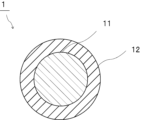
- FIG. 1 is a cross-sectional view schematically showing adhesive particles according to a first embodiment of the present invention.
- FIG. 2 is a cross-sectional view schematically showing a laminate using adhesive particles according to the first embodiment of the present invention.
- FIG. 3 is a cross-sectional view schematically showing a PDLC-type light control laminate using adhesive particles according to the first embodiment of the present invention.
- FIG. 4 is a cross-sectional view schematically showing an SPD-type light control laminate using adhesive particles according to the first embodiment of the present invention.
- (meth)acrylate means one or both of “acrylate” and “methacrylate”
- (meth)acryl means one or both of "acrylic” and “methacrylic”. means both.
- An adhesive particle according to the present invention comprises a substrate particle and a coating portion arranged on the surface of the substrate particle.
- the covering portion contains a thermosetting resin.
- the adhesive particles according to the present invention have a 10% K value at 25° C. of 100 N/mm 2 or more and 3000 N/mm 2 or less.
- the adhesive particles according to the present invention have the above configuration, the adhesiveness of the adhesive particles can be sufficiently enhanced.
- the adhesive particles according to the present invention have the above configuration, when the adhesive particles are used as a material for the spacer particles, the separation of the spacer particles from the base material can be suppressed. and the gap between the substrates can be controlled with high precision.
- the adhesive particles according to the present invention have the above configuration, it is possible to prevent the substrate from being scratched.
- peeling of the base material can be suppressed when the particles are used in the light control laminate.
- the adhesive particles according to the present invention are provided with the above configuration, for example, even if the laminate has a curved surface portion, the adhesive particles do not move on the curved surface portion, and the base material The uniformity of the gap between them can be ensured.
- the adhesive particles according to the present invention can suppress the peeling of the adhesive particles from the substrate even if the laminate has a curved surface portion, so that the uniformity of the gap between the substrates can be ensured. can do. As a result, it is possible to suppress the occurrence of problems such as color unevenness in the liquid crystal display device caused by non-uniformity of the gap.
- a spherical shape is not limited to a true spherical shape, but includes a substantially spherical shape, and includes, for example, a shape having an aspect ratio (major axis/minor axis) of 1.5 or less.
- the 10% K value at 25° C. of the adhesive particles is 100 N/mm 2 or more and 3000 N/mm 2 or less.
- the 10% K value at 25° C. of the adhesive particles is preferably 200 N/mm 2 or more, more preferably 300 N/mm 2 or more, still more preferably 1000 N/mm 2 or more, and preferably 2800 N/mm 2 or less. , more preferably 2500 N/mm 2 or less, still more preferably 2000 N/mm 2 or less.
- the 10% K value at 25°C of the adhesive particles is equal to or higher than the lower limit and equal to or lower than the upper limit, the effects of the present invention can be exhibited more effectively. Also, the substrate can be prevented from being damaged. Further, when the 10% K value at 25° C. of the adhesive particles is equal to or higher than the lower limit and equal to or lower than the upper limit, peeling of the substrate can be further suppressed when used in the light control laminate. can.
- the 10% K value at 25°C of the adhesive particles can be measured as follows. Using a microcompression tester, the adhesive particles are compressed at 25° C. with a smooth indenter end face of a cylinder (50 ⁇ m in diameter, made of diamond) under conditions of applying a maximum test load of 20 mN for 60 seconds. The load value (N) and compression displacement (mm) at this time are measured. From the measured values obtained, the 10% K value at 25° C. can be obtained by the following formula. As the microcompression tester, for example, "Fischer Scope H-100" manufactured by Fisher Co., Ltd. is used.
- the 10% K value at 25° C. after heating the adhesive particles at 120° C. for 1 hour is preferably 110 N/mm 2 or more, more preferably 150 N/mm 2 or more, and still more preferably 300 N/mm 2 or more. Yes, preferably 3500 N/mm 2 or less, more preferably 3000 N/mm 2 or less, and even more preferably 2800 N/mm 2 or less.
- the 10% K value at 25°C after heating the adhesive particles at 120°C for 1 hour is at least the above lower limit and below the above upper limit, the effect of the present invention can be exhibited more effectively. . Also, the substrate can be prevented from being damaged. Further, when the 10% K value at 25° C. after heating the adhesive particles at 120° C. for 1 hour is equal to or higher than the lower limit and equal to or lower than the upper limit, when used in a light control laminate, the base material delamination can be further suppressed.
- the 10% K value at 25°C after heating the adhesive particles at 120°C for 1 hour (10% K value at 25°C after heating) can be measured as follows.
- the adhesive particles are heated at 120° C. for 1 hour in a blower constant temperature thermostat (for example, “DKN302” manufactured by Yamato Scientific Co., Ltd.).
- a microcompression tester the adhesive particles after heating are compressed at 25° C. with a smooth indenter end face of a cylinder (50 ⁇ m in diameter, made of diamond) under conditions of applying a maximum test load of 20 mN for 60 seconds.
- the load value (N) and compression displacement (mm) at this time are measured. From the measured values obtained, the 10% K value at 25° C. after heating can be obtained by the following formula.
- the microcompression tester for example, "Fischer Scope H-100" manufactured by Fisher Co., Ltd. is used.
- a method for controlling the 10% K value at 25° C. after heating the adhesive particles at 120° C. for 1 hour to a suitable range a method of adjusting the 10% K value at 25° C. of the substrate particles. , a method of using a preferable material for the covering portion, and a method of adjusting the contents of the thermosetting resin used for the covering portion and a curing agent to be described later.
- the 10% K value at 25° C. of the substrate particles is less than 100 N/mm 2 , it is preferable to control the 10% K value by using a preferred material for the coating portion.
- the compression recovery rate of the adhesive particles at 25°C is preferably 5% or more, more preferably 10% or more, and preferably 50% or less, more preferably 40% or less.
- the compression recovery rate at 25° C. of the adhesive particles is equal to or higher than the lower limit and equal to or lower than the upper limit, the effects of the present invention can be exhibited more effectively. Further, when the compression recovery rate of the adhesive particles at 25°C is equal to or higher than the lower limit and equal to or lower than the upper limit, peeling of the base material can be further suppressed when used in the light control laminate. .
- the compression recovery rate of the adhesive particles at 25°C can be measured as follows.
- a single adhesive particle that has been dispersed is subjected to a smooth indenter end face of a cylinder (50 ⁇ m in diameter, made of diamond) at 25° C. toward the center of the adhesive particle at an origin load value of 1.5°C.
- a compression recovery rate is derived by applying a load under the conditions of 0 mN and a reverse load value of 10 mN and analyzing the recovery behavior after the load is removed. By measuring the load-compression displacement during this period, the compression recovery rate can be obtained from the following formula. Note that the load speed is 0.33 mN/sec.
- the microcompression tester for example, "Fischer Scope H-100" manufactured by Fisher Co., Ltd. is used.
- Compression recovery rate (%) [L2/L1] x 100
- L1 Compressive displacement from the origin load value to the reverse load value when the load is applied
- L2 Unloading displacement from the reverse load value to the origin load value when releasing the load
- the particle size of the adhesive particles is preferably 1 ⁇ m or more, more preferably 3 ⁇ m or more, still more preferably 10 ⁇ m or more, preferably 150 ⁇ m or less, more preferably 100 ⁇ m or less, and It is preferably 50 ⁇ m or less.
- the particle diameter of the adhesive particles means the diameter when the adhesive particles are spherical, and when the adhesive particles have a shape other than a spherical shape, it is assumed to be a true sphere corresponding to the volume. means the diameter when The particle size of the adhesive particles is preferably an average particle size, more preferably a number average particle size.
- the average particle size of the adhesive particles can be measured by any particle size distribution analyzer. For example, it can be measured using a particle size distribution measuring apparatus using the principle of laser light scattering, electrical resistance value change, image analysis after imaging, or the like.
- a particle size distribution measuring device (“Multisizer 4" manufactured by Beckman Coulter) is used to measure the particle size of about 100,000 adhesive particles, and the average value is A method of calculating is exemplified.
- the CV value of the particle diameter of the adhesive particles is preferably 10% or less, more preferably 7% or less.
- the smaller the CV value of the particle diameter of the adhesive particles the better.
- the CV value of the particle diameter of the adhesive particles is equal to or less than the above upper limit. is performed, the adhesive particles can follow the laminate, and movement of the adhesive particles can be suppressed.
- the lower limit of the CV value of the particle diameter of the adhesive particles is not particularly limited.
- the CV value of the particle diameter of the adhesive particles may be 0% or more, or 7% or more.
- the CV value (variation coefficient) of the particle size of the adhesive particles can be measured as follows.
- CV value (%) ( ⁇ /Dn) ⁇ 100 ⁇ : standard deviation of the particle size of the adhesive particles Dn: average value of the particle size of the adhesive particles
- the aspect ratio of the adhesive particles is preferably 1.5 or less, more preferably 1.3 or less.
- the above aspect ratio indicates major axis/minor axis.
- the aspect ratio is obtained by observing 10 arbitrary adhesive particles with an electron microscope or an optical microscope, defining the maximum diameter and the minimum diameter as the major diameter and the minor diameter, respectively, and averaging the major diameter / minor diameter of each spherical adhesive particle. It is preferable to obtain by calculating the value.
- the lower limit of the aspect ratio of the adhesive particles is not particularly limited.
- the aspect ratio of the adhesive particles may be 1.0 or more, or 1.1 or more.
- the tensile yield stress of the adhesive particles is preferably 0.07 MPa or more, more preferably 0.10 MPa or more, and still more preferably 0.12 MPa or more. is preferred.
- the upper limit of the tensile yield stress of the adhesive particles is not particularly limited. In the following adhesion test A, the tensile yield stress of the adhesive particles may be 0.12 MPa or less, or 0.07 MPa or less.
- Adhesion test A Glass substrates are prepared as the first base material and the second base material. 14000 particles/mm 2 of adhesive particles are scattered on the surface of the first substrate. A second substrate is then placed over the adhesive particles. The adhesive particles are adhered to the first and second substrates by heating at 120° C. for 1 hour at a pressure of 5 kgf/cm 2 in accordance with the method of JIS K6850 to prepare a test body (test sample). .
- a Tensilon universal material testing machine for example, "RTI-1310" manufactured by A&D Co., Ltd.
- the adhesive strength of the specimen obtained at a tensile speed of 20 mm / min and a load cell rating of 1000 N is measured at 23 ° C. . This measured value is taken as the tensile yield stress of the adhesive particles.
- the 90° peel strength of the adhesive particles is preferably 0.1 N/30 mm or more, more preferably 0.5 N/30 mm or more, and still more preferably is preferably 1.0 N/30 mm or more.
- the upper limit of the 90° peel strength of the adhesive particles is not particularly limited.
- the 90° peel strength of the adhesive particles may be 10.0 N/30 mm or less, or 0.1 N/30 mm or less.
- Adhesion test B As the first base material and the second base material, according to a known method, films with alignment films are prepared by casting a polyimide solution on a PET film, drying, and rubbing. 14000 particles/mm 2 of adhesive particles are scattered on the surface of the first substrate. Then, according to the method of JIS K6850, the pressure is 5 kgf/cm 2 and the adhesive particles are heated at 120° C. for 1 hour to adhere the adhesive particles onto the first and second substrates, thereby forming a test body (test sample). make. Based on JIS K6854:1999, the measurement is performed using a tensile tester (for example, "Autograph AGS" manufactured by Shimadzu Corporation) at a tensile speed of 50 mm/sec. This measured value is taken as the 90° peel strength of the adhesive particles.
- a tensile tester for example, "Autograph AGS” manufactured by Shimadzu Corporation
- the adhesive particles according to the present invention are suitably used as materials for spacer particles.
- the adhesive particles according to the present invention are particularly suitable for use as a material for spacer particles in a light control laminate.
- the adhesive particles may be used as a material for spacer particles for a light control glass, or may be used as a material for spacer particles for a light control film.
- the adhesive particles are preferably used as a material for spacer particles for light control glass or a material for spacer particles for light control film.
- FIG. 1 is a cross-sectional view schematically showing adhesive particles according to the first embodiment of the present invention.
- the adhesive particles 1 include base particles 11 and coating portions 12 arranged on the surfaces of the base particles 11 .
- the covering portion 12 covers the surfaces of the substrate particles 11 .
- the adhesive particles 1 are coated particles in which the surfaces of the substrate particles 11 are coated with the coating portion 12 .
- the covering portion may completely cover the surface of the base particle, or may not completely cover the surface of the base particle.
- the substrate particles may have portions not covered with the covering portion.
- the covering portion 12 contains a thermosetting resin.
- the adhesive particles 1 have a 10% K value at 25° C. of 100 N/mm 2 or more and 3000 N/mm 2 or less.
- the material of the substrate particles is not particularly limited.
- the substrate particles may contain an organic material or may contain an inorganic material.
- organic material examples include polyolefin resins such as polyethylene, polypropylene, polystyrene, polyvinyl chloride, polyvinylidene chloride, polyisobutylene, and polybutadiene; acrylic resins such as polymethyl methacrylate and polymethyl acrylate; polycarbonates, polyamides, phenol formaldehyde resins, and melamine.
- polyolefin resins such as polyethylene, polypropylene, polystyrene, polyvinyl chloride, polyvinylidene chloride, polyisobutylene, and polybutadiene
- acrylic resins such as polymethyl methacrylate and polymethyl acrylate
- polycarbonates polyamides, phenol formaldehyde resins, and melamine.
- Formaldehyde resin benzoguanamine formaldehyde resin, urea formaldehyde resin, phenol resin, melamine resin, benzoguanamine resin, urea resin, epoxy resin, unsaturated polyester resin, saturated polyester resin, polyethylene terephthalate, polysulfone, polyphenylene oxide, polyacetal, polyimide, polyamideimide, Examples include polyetheretherketone, polyethersulfone, and divinylbenzene polymer.
- the divinylbenzene polymer may be a divinylbenzene copolymer.
- the divinylbenzene copolymer and the like examples include a divinylbenzene-styrene copolymer and a divinylbenzene-(meth)acrylate copolymer. Since the hardness of the adhesive particles and the substrate particles can be easily controlled within a suitable range, the substrate particles are formed by polymerizing one or more polymerizable monomers having an ethylenically unsaturated group. It preferably contains a polymer.
- the polymerizable monomer having an ethylenically unsaturated group includes a non-crosslinking monomer and a crosslinkable monomer. and monomers of the same type.
- non-crosslinkable monomers examples include vinyl compounds such as styrene monomers such as styrene, ⁇ -methylstyrene, and chlorostyrene; vinyl ether compounds such as methyl vinyl ether, ethyl vinyl ether, and propyl vinyl ether; vinyl acetate, vinyl butyrate, Acid vinyl ester compounds such as vinyl laurate and vinyl stearate; halogen-containing monomers such as vinyl chloride and vinyl fluoride; ) Alkyl ( meth) acrylate compounds; oxygen atom-containing (meth) acrylate compounds such as 2-hydroxyethyl (meth) acrylate, glycerol (meth) acrylate, polyoxyethylene (meth) acrylate, glycidyl (meth) acrylate; (meth) acrylonitrile and the like Nitrile-containing monomers; halogen-containing (meth)acrylate compounds such as trifluoromethyl (meth)acrylate and pentafluor
- crosslinkable monomers examples include vinyl monomers such as divinylbenzene, 1,4-divinyloxybutane and divinylsulfone as vinyl compounds; and tetramethylolmethane tetra(meth)acrylate as (meth)acrylic compounds.
- polytetramethylene glycol diacrylate tetramethylolmethane tri(meth)acrylate, tetramethylolmethane di(meth)acrylate, trimethylolpropane tri(meth)acrylate, dipentaerythritol hexa(meth)acrylate, dipentaerythritol penta(meth)acrylate ) acrylate, glycerol tri(meth)acrylate, glycerol di(meth)acrylate, polyethylene glycol di(meth)acrylate, polypropylene glycol di(meth)acrylate, polytetramethylene glycol di(meth)acrylate, 1,4-butanediol di Polyfunctional (meth)acrylate compounds such as (meth)acrylates; triallyl (iso)cyanurate, triallyl trimellitate, diallyl phthalate, diallyl acrylamide, diallyl ether as allyl compounds; tetrameth
- the substrate particles can be obtained by polymerizing the polymerizable monomer having the ethylenically unsaturated group.
- the polymerization method is not particularly limited, and includes known methods such as radical polymerization, ionic polymerization, polycondensation (condensation polymerization, polycondensation), addition condensation, living polymerization, and living radical polymerization.
- Other polymerization methods include suspension polymerization in the presence of a radical polymerization initiator.
- Examples of the inorganic material include silicate glass, borosilicate glass, lead glass, soda lime glass, alumina and alumina silicate glass.
- the substrate particles may be formed only of the organic material, may be formed only of the inorganic material, or may be formed of both the organic material and the inorganic material. From the viewpoint of easily controlling the compression properties of the substrate particles and the adhesive particles within a suitable range, the substrate particles may be made of only an organic material, or may be made of both an organic material and an inorganic material. It is preferable that
- the base particles may contain other components as necessary.
- the other components include coloring agents, polymerization inhibitors, polymerization initiators, pigment dispersants, polymer dispersants, surfactants, and the like. Only one of the other components may be used, or two or more thereof may be used in combination.
- the 10% K value at 25° C. of the substrate particles is preferably 100 N/mm 2 or more, more preferably 300 N/mm 2 or more, still more preferably 1000 N/mm 2 or more, and preferably 3000 N/mm 2 or less. , more preferably 2500 N/mm 2 or less, still more preferably 2000 N/mm 2 or less.
- the 10% K value at 25° C. of the substrate particles is equal to or higher than the lower limit and equal to or lower than the upper limit, the effects of the present invention can be exhibited even more effectively. Also, the substrate can be prevented from being damaged. Further, when the 10% K value at 25° C. of the substrate particles is at least the above lower limit and below the above upper limit, when the obtained adhesive particles are used in a light control laminate, the substrate does not peel off. can be further suppressed.
- the 10% K value at 25°C of the base particles can be measured as follows. Using a microcompression tester, the substrate particles are compressed at 25° C. with a smooth indenter end face of a cylinder (diameter 50 ⁇ m, made of diamond) under conditions of applying a maximum test load of 20 mN for 60 seconds. The load value (N) and compression displacement (mm) at this time are measured. From the measured values obtained, the 10% K value at 25° C. can be obtained by the following formula. As the microcompression tester, for example, "Fischer Scope H-100" manufactured by Fisher Co., Ltd. is used.
- the compression recovery rate of the substrate particles at 25°C is preferably 5% or more, more preferably 10% or more, and preferably 50% or less, more preferably 40% or less.
- the compression recovery rate at 25° C. of the substrate particles is equal to or higher than the lower limit and equal to or lower than the upper limit, the effects of the present invention can be exhibited more effectively. Further, when the compression recovery rate of the substrate particles at 25° C. is equal to or more than the lower limit and equal to or less than the upper limit, peeling of the substrate can be further suppressed when used in the light control laminate. .
- the compression recovery rate of the substrate particles at 25°C can be measured as follows.
- one dispersed substrate particle is subjected to a smooth indenter end face of a cylinder (50 ⁇ m in diameter, made of diamond) at 25° C. toward the center of the substrate particle with an origin load value of 1.5°C.
- a load is applied under the conditions of 0 mN and a reverse load value of 10 mN, and the compression recovery rate is derived by analyzing the recovery behavior after the load is removed. By measuring the load-compression displacement during this period, the compression recovery rate can be obtained from the following formula. Note that the load speed is 0.33 mN/sec.
- the microcompression tester for example, "Fischer Scope H-100" manufactured by Fisher Co., Ltd. is used.
- Compression recovery rate (%) [L2/L1] x 100
- L1 Compressive displacement from the origin load value to the reverse load value when the load is applied
- L2 Unloading displacement from the reverse load value to the origin load value when releasing the load
- the particle size of the substrate particles is preferably 1.0 ⁇ m or more, more preferably 5.0 ⁇ m or more, still more preferably 10 ⁇ m or more, and more preferably 50 ⁇ m or less, more preferably It is 40 ⁇ m or less, more preferably 30 ⁇ m or less.
- the particle size of the substrate particles is preferably the average particle size, more preferably the number average particle size.
- the particle diameter of the substrate particles is preferably determined by measuring the particle diameters of approximately 100,000 substrate particles using a particle size distribution analyzer and calculating the average particle diameter. Examples of the particle size distribution analyzer include "Multisizer 4" manufactured by Beckman Coulter.
- the CV value (variation coefficient) of the particle size of the substrate particles is preferably 10% or less, more preferably 7% or less, and even more preferably 5% or less.
- the lower limit of the CV value of the particle diameter of the substrate particles is not particularly limited.
- the CV value of the particle diameter of the substrate particles may be 2% or more.
- the CV value of the particle diameter of the substrate particles is expressed by the following formula.
- CV value (%) ( ⁇ /Dn) ⁇ 100 ⁇ : standard deviation of particle size of substrate particles Dn: average value of particle size of substrate particles
- the coating part is arranged on the surface of the substrate particle.
- the surface area (coverage) covered by the coating portion on the surface of the substrate particles is preferably 80% or more, out of 100% of the total surface area of the substrate particles. Preferably it is 90% or more.
- the upper limit of the coverage rate is not particularly limited. The coverage may be 100% or less.
- the above coverage is set to an image magnification of 10,000 times using a field emission scanning electron microscope (FE-SEM), 20 adhesive particles are randomly selected, and the surface of each adhesive particle is Observe. The percentage of the surface area of the portion of the adhesive particles covered with the substrate particles relative to the projected area of the entire substrate particles is measured, and the arithmetic mean is taken as the coverage.
- FE-SEM field emission scanning electron microscope
- the thickness of the coating portion is preferably 0.5 ⁇ m or more, more preferably 0.7 ⁇ m or more, still more preferably 1.0 ⁇ m or more, and preferably 8.0 ⁇ m or less. It is preferably 5.0 ⁇ m or less.
- the thickness of the coating portion means the thickness of the coating portion only in the portion where the coating portion is arranged on the surface of the substrate particle. A portion of the surface of the base material particle where there is no coating portion is not taken into consideration when calculating the thickness of the coating portion.
- the covering portion may be a single layer or two or more layers (multilayer).
- the thickness of the covering portion means the thickness of the entire covering portion.
- the materials forming each layer of the covering portion may be different.
- the thickness of the coating portion can be calculated from the difference between the particle size of the substrate particles and the particle size of the adhesive particles.
- the thickness of the coating portion can also be determined by observing the cross section of the adhesive particles using, for example, a transmission electron microscope (TEM).
- TEM transmission electron microscope
- the ratio of the thickness of the coating portion to the particle size of the substrate particles is preferably 0.001 or more, more preferably It is 0.01 or more, preferably 1.0 or less, more preferably 0.5 or less, and still more preferably 0.4 or less.
- the covering portion contains a thermosetting resin.
- thermosetting resins examples include epoxy resins, crosslinkable acrylic resins, phenol resins, melamine resins, urethane resins, and crosslinkable polyamide resins.
- the thermosetting resin in the coating preferably contains an epoxy resin, a crosslinkable acrylic resin, or a crosslinkable polyamide resin, and more preferably contains an epoxy resin.
- the epoxy resin is preferably a polyfunctional epoxy resin.
- the polyfunctional epoxy resin may be a bifunctional epoxy resin, a bifunctional or higher functional epoxy resin, a trifunctional epoxy resin, or a trifunctional or higher functional epoxy resin. , a tetrafunctional epoxy resin, or a tetrafunctional or higher epoxy resin.
- Bifunctional epoxy resins include bisphenol A type epoxy resins and bisphenol F type epoxy resins.
- the trifunctional epoxy resins include triazine-type epoxy resins and glycidylamine-type epoxy resins.
- Examples of the tetrafunctional epoxy resins include tetrakisphenolethane type epoxy resins and glycidylamine type epoxy resins. Only one type of the epoxy resin may be used, or two or more types may be used in combination.
- the above thermosetting resin is preferably used in combination with a curing agent.
- the curing agent cures the thermosetting resin.
- the curing agent is not particularly limited. Examples of the curing agent include imidazole curing agents, amine curing agents, phenol curing agents, thiol curing agents, and acid anhydride curing agents. Only one kind of the curing agent may be used, or two or more kinds thereof may be used in combination. From the viewpoint of easily controlling the compression properties of the adhesive particles within a suitable range, the curing agent is preferably an amine curing agent.
- the imidazole curing agent is not particularly limited.
- Examples of the imidazole curing agent include 2-methylimidazole, 2-ethyl-4-methylimidazole, 1-cyanoethyl-2-phenylimidazole, 1-cyanoethyl-2-phenylimidazolium trimellitate, 2,4-diamino-6.
- the thiol curing agent is not particularly limited.
- the thiol curing agent may be a polythiol curing agent.
- Examples of the thiol curing agent include trimethylolpropane tris-3-mercaptopropionate, pentaerythritol tetrakis-3-mercaptopropionate, and dipentaerythritol hexa-3-mercaptopropionate.
- the above amine curing agent is not particularly limited.
- examples of the amine curing agent include ethylenediamine, hexamethylenediamine, octamethylenediamine, decamethylenediamine, norbornanediamine, 3,9-bis(3-aminopropyl)-2,4,8,10-tetraspiro[5.5].
- undecane bis(4-aminocyclohexyl)methane, phenylenediamine, 2,2-bis[4-(4-aminophenoxy)phenyl]propane, metaphenylenediamine, diaminodiphenylmethane, diaminophenyl ether, metaxylenediamine, diaminonaphthalene, bisaminomethylcyclohexane, diaminodiphenylsulfone, and the like.
- the amine curing agent is ethylenediamine, hexamethylenediamine, octamethylenediamine, metaphenylenediamine, norbornanediamine, diaminodiphenylmethane, diaminodiphenylsulfone, phenylenediamine, or 2,2-bis[4-(4-aminophenoxy)phenyl].
- Propane is preferred.
- the amine curing agent is the preferred compound described above, the compression properties of the adhesive particles can be easily controlled within a suitable range.
- the amine curing agent may be ethylenediamine, norbornanediamine, phenylenediamine, or 2,2-bis[4-(4-aminophenoxy)phenyl ] Propane is more preferred, and norbornanediamine is even more preferred.
- the acid anhydride curing agent is not particularly limited.
- As the acid anhydride curing agent a wide range of acid anhydrides commonly used as curing agents for thermosetting resins such as epoxy resins can be used.
- Examples of the acid anhydride curing agent include phthalic anhydride, tetrahydrophthalic anhydride, trialkyltetrahydrophthalic anhydride, hexahydrophthalic anhydride, methylhexahydrophthalic anhydride, methyltetrahydrophthalic anhydride, and methylbutenyltetrahydrophthalic anhydride.
- anhydrides of phthalic acid derivatives maleic anhydride, nadic anhydride, methyl nadic anhydride, glutaric anhydride, succinic anhydride, glycerin bis trimellitic anhydride monoacetate, and ethylene glycol bis trimellitic anhydride.
- acid anhydride curing agent trifunctional acid anhydride curing agent such as trimellitic anhydride, and pyromellitic anhydride, benzophenone tetracarboxylic anhydride, methylcyclohexene tetracarboxylic anhydride, polyazelaic anhydride, etc. and a tetrafunctional or higher acid anhydride curing agent.
- the polymerization method is not particularly limited, and radical polymerization, ionic polymerization, polycondensation (condensation polymerization, condensation polymerization), addition condensation, living polymerization, living radical polymerization, etc. Polymerization can be carried out by known methods.
- the above adhesive particles can be easily obtained by performing dispersion polymerization or the like using a material containing a polyfunctional epoxy resin and a curing agent in a solution.
- a method of suspension polymerization using a solution in which a polyfunctional epoxy resin and a curing agent are dissolved as an oil layer and a method of polymerizing by swelling a solution in which a polyfunctional epoxy resin and a curing agent are dissolved using non-crosslinked seed particles. It can be obtained by a method such as a seed polymerization method.
- the content of the thermosetting resin in 100% by weight of the covering portion is preferably 30% by weight or more, more preferably 50% by weight or more, still more preferably 60% by weight or more, and particularly preferably 80% by weight or more. , preferably 100% by weight or less, more preferably 95% by weight or less, and even more preferably 90% by weight or less.
- the adhesiveness can be further enhanced.
- the content of the thermosetting resin in 100% by weight of the adhesive particles is preferably 10% by weight or more, more preferably 20% by weight or more, still more preferably 30% by weight or more, and particularly preferably 40% by weight or more. Yes, preferably 75% by weight or less, more preferably 70% by weight or less, and even more preferably 60% by weight or less.
- the adhesiveness can be further enhanced.
- the covering portion preferably contains a compound having a structure represented by the following formula (1).
- R1 and R2 each represent an organic group having an amino group, an organic group having an epoxy group, an organic group having an amide group, an organic group having an isocyanate group, or an organic group having a hydroxy group.
- R3 represents an alkyl group having 1 to 2 carbon atoms, an alkoxy group having 1 to 2 carbon atoms, or a vinyl group.
- p is 1 or 1.5.
- R4 represents a hydrogen atom, an alkyl group having 1 or 2 carbon atoms, an alkoxy group having 1 or 2 carbon atoms, or a vinyl group.
- p is 1.5
- q is 0 (R4 is absent).
- n represents an integer from 1 to 100;
- the above formula (1) is represented by the following formula (1A) when p is 1.
- R1 and R2 each represent an organic group having an amino group, an organic group having an epoxy group, an organic group having an amide group, an organic group having an isocyanate group, or an organic group having a hydroxyl group.
- R3 represents an alkyl group having 1 to 2 carbon atoms, an alkoxy group having 1 to 2 carbon atoms, or a vinyl group.
- R4 represents a hydrogen atom, an alkyl group having 1 to 2 carbon atoms, an alkoxy group having 1 to 2 carbon atoms, or a vinyl group.
- n represents an integer from 1 to 100;
- the above formula (1) is represented by the following formula (1B) when p is 1.5.
- R1 and R2 each represent an organic group having an amino group, an organic group having an epoxy group, an organic group having an amide group, an organic group having an isocyanate group, or an organic group having a hydroxy group.
- R3 represents an alkyl group having 1 to 2 carbon atoms, an alkoxy group having 1 to 2 carbon atoms, or a vinyl group.
- n represents an integer from 1 to 100;
- a compound having a structure represented by the above formula (1B) is generally called a polysilsesquioxane.
- q in the above formula (1) is 0 and R4 does not exist.
- R1 and R2 are each an organic group having an amino group, an organic group having an epoxy group, an organic group having an amide group, an organic group having an isocyanate group, or represents an organic group having a hydroxy group.
- R1 and R2 may be the same or different.
- R1 and R2 are each preferably an organic group having an amino group or an organic group having an epoxy group. .
- R3 represents an alkyl group having 1 to 2 carbon atoms, an alkoxy group having 1 to 2 carbon atoms, or a vinyl group. From the viewpoint of further improving the adhesiveness, in the above formulas (1), (1A) and (1B), R3 is preferably a methyl group, an ethyl group or a vinyl group, more preferably a methyl group. .
- R4 represents a hydrogen atom, an alkyl group having 1 to 2 carbon atoms, an alkoxy group having 1 to 2 carbon atoms, or a vinyl group. From the viewpoint of further enhancing adhesiveness, in the above formulas (1) and (1A), R4 is preferably a methyl group, an ethyl group or a vinyl group, more preferably a methyl group.
- n represents an integer of 1-100. From the viewpoint of further increasing the adhesiveness, in the above formulas (1), (1A) and (1B), n is preferably an integer of 2 or more, preferably an integer of 50 or less, more preferably an integer of 10 or less is.
- R3 and R4 may be the same or different.
- a plurality of R3 may be the same or different.
- a plurality of R4 may be the same or different.
- the compound having the structure represented by the above formula (1) may include the compound having the structure represented by the above formula (1A), and the compound having the structure represented by the above formula (1B). It may contain a compound having a structure represented by the above formula (1A) and a compound having a structure represented by the above formula (1B).
- the compound having the structure represented by formula (1) may include the compound having the structure represented by formula (1A) and the compound having the structure represented by formula (1B).
- the compound having the structure represented by the formula (1) may be a compound having the structure represented by the formula (1A) and the structure represented by the formula (1B).
- the structure represented by the above formula (1) may be the structure represented by the above formula (1A) or the structure represented by the above formula (1B).
- the compound having the structure represented by formula (1) above preferably contains the compound having the structure represented by formula (1A) above.
- the structure represented by the above formula (1) is preferably the structure represented by the above formula (1A).
- the content of the compound having the structure represented by the formula (1) in 100% by weight of the covering portion is preferably 1% by weight or more, more preferably 5% by weight or more, and still more preferably 10% by weight or more. , preferably 50% by weight or less, more preferably 40% by weight or less, and even more preferably 30% by weight or less.
- the adhesiveness can be further enhanced.
- the compound having the structure represented by the formula (1) includes both the compound having the structure represented by the formula (1A) and the compound having the structure represented by the formula (1B). be.
- the above content represents the sum of the content of the compound having the structure represented by formula (1A) and the content of the compound having the structure represented by formula (1B).
- the covering part may contain other components as necessary.
- the other components include coloring agents, polymerization initiators, polymerization inhibitors, adhesion imparting agents, anti-coloring agents, surfactants, polymer dispersants, and the like. Only one of the other components may be used, or two or more thereof may be used in combination.
- a laminate according to the present invention (hereinafter sometimes referred to as a laminate (A)) includes a first base material, a second base material, and the first base material and the second base material. and spacer particles disposed between.
- the spacer particles adhere to the first base material and the second base material.
- the material of the spacer particles contains the adhesive particles.
- the spacer particles can be formed in the laminate (A) by thermosetting the thermosetting resin or by reacting the compound having the structure represented by the formula (1). can. Further, the spacer particles can be formed between the first base material and the second base material by heat-curing the thermosetting resin or reacting the compound having the structure represented by the formula (1). It can be adhered to materials.
- a laminate (B) includes a first base material, a second base material, and the first base material and the second base material. spacer particles disposed between the substrate of the In the laminate (B), the spacer particles adhere to the first base material and the second base material.
- the material of the spacer particles contains the adhesive particles, and the spacer particles contain a compound having a structural unit represented by the following formula (11).
- the spacer particles can be formed in the laminate (B) by thermosetting the thermosetting resin or reacting the compound having the structure represented by the formula (1). can.
- the spacer particles can be formed between the first base material and the second base material by heat-curing the thermosetting resin or reacting the compound having the structure represented by the formula (1). It can be adhered to materials.
- R3 represents an alkyl group having 1 to 2 carbon atoms, an alkoxy group having 1 to 2 carbon atoms, or a vinyl group.
- p is 1 or 1.5.
- R4 represents a hydrogen atom, an alkyl group having 1 or 2 carbon atoms, an alkoxy group having 1 or 2 carbon atoms, or a vinyl group.
- p is 1.5, q is 0 (R4 is absent).
- n represents an integer from 1 to 100;
- the adhesiveness can be sufficiently improved, the separation of the spacer particles from the substrate is suppressed, and , the gap between the substrates can be controlled with high precision.
- the layered product (A) and the layered product (B) according to the present invention are provided with the above configuration, it is possible to prevent the substrate from being scratched.
- the layered product (A) and the layered product (B) according to the present invention have the above-described configuration, so that peeling of the base material can be suppressed when used in the light control layered product. .
- the layered product (A) and the layered product (B) according to the present invention are provided with the above-described configuration, for example, even if the layered product has a curved surface portion, the spacer particles are formed in the curved surface portion. The uniformity of the gap between the substrates can be ensured without being crushed. Moreover, even if the laminate has a curved surface portion, separation of the spacer particles from the base material can be suppressed, so that the uniformity of the gap between the base materials can be ensured. As a result, it is possible to suppress the occurrence of problems such as color unevenness in the liquid crystal display device caused by non-uniformity of the gap.
- R3 represents an alkyl group having 1 to 2 carbon atoms, an alkoxy group having 1 to 2 carbon atoms, or a vinyl group.
- R4 represents a hydrogen atom, an alkyl group having 1 to 2 carbon atoms, an alkoxy group having 1 to 2 carbon atoms, or a vinyl group.
- n represents an integer from 1 to 100;
- R3 represents an alkyl group having 1 to 2 carbon atoms, an alkoxy group having 1 to 2 carbon atoms, or a vinyl group.
- n represents an integer from 1 to 100;
- a compound having a structural unit represented by the above formula (11B) is generally called a polysilsesquioxane.
- q in the above formula (11) is 0 and R4 does not exist.
- R3 represents an alkyl group having 1 to 2 carbon atoms, an alkoxy group having 1 to 2 carbon atoms, or a vinyl group. From the viewpoint of further improving adhesiveness, in the above formulas (11), (11A) and (11B), R3 is preferably a methyl group, an ethyl group or a vinyl group, more preferably a methyl group. .
- R4 represents a hydrogen atom, an alkyl group having 1 to 2 carbon atoms, an alkoxy group having 1 to 2 carbon atoms, or a vinyl group. From the viewpoint of further enhancing adhesiveness, R4 in the above formulas (11) and (11A) is preferably a methyl group, an ethyl group or a vinyl group, more preferably a methyl group.
- n represents an integer of 1-100. From the viewpoint of further increasing the adhesiveness, in the above formulas (11), (11A) and (11B), n is preferably an integer of 2 or more, preferably an integer of 50 or less, more preferably an integer of 10 or less is.
- R3 and R4 may be the same or different.
- a plurality of R3 when n is 2 or more, a plurality of R3 may be the same or different.
- a plurality of R4 when n is 2 or more, a plurality of R4 may be the same or different.
- the compound having a structural unit represented by the formula (11) may contain a compound having a structural unit represented by the formula (11A), and has a structural unit represented by the formula (11B).
- a compound having a structural unit represented by the above formula (11A) and a compound having a structural unit represented by the above formula (11B) may be included.
- a compound having a structural unit represented by the formula (11) may include a compound having a structural unit represented by the formula (11A) and a compound having a structural unit represented by the formula (11B). . In this case, even if the compound having the structural unit represented by the formula (11) is a compound having the structural unit represented by the formula (11A) and the structural unit represented by the formula (11B) good.
- the structural unit represented by formula (11) above may be the structural unit represented by formula (11A) above, or the structural unit represented by formula (11B) above.
- the compound having the structural unit represented by formula (11) preferably contains a compound having the structural unit represented by formula (11A).
- the structural unit represented by formula (11) above is preferably the structural unit represented by formula (11A) above.
- the content of the compound having the structural unit represented by the above formula (11) is preferably 1% by weight or more, more preferably 5% by weight, based on 100% by weight of the spacer particles. Above, more preferably 10% by weight or more, preferably 50% by weight or less, more preferably 40% by weight or less, and even more preferably 30% by weight or less.
- the compound having the structural unit represented by the formula (11) includes both the compound having the structural unit represented by the formula (11A) and the compound having the structural unit represented by the formula (11B). may contain. In this case, the content represents the sum of the content of the compound having the structural unit represented by formula (11A) and the content of the compound having the structural unit represented by formula (11B).
- the spacer particles can be obtained by heating the adhesive particles.
- the spacer particles can be obtained, for example, by heating the adhesive particles at 80° C. to 150° C. for 0.5 hours to 3 hours. More specific conditions can be obtained, for example, by heating the adhesive particles at 120° C. for 1 hour.
- FIG. 2 is a cross-sectional view schematically showing a laminate using adhesive particles according to the first embodiment of the present invention.
- the spacer particles 1X are adhered to the first base material 2 and the second base material 3 .
- the material of the spacer particles 1X contains the adhesive particles.
- the spacer particles 1X contain a compound having a structural unit represented by formula (11) above.
- the spacer particles are formed in the layered body 51 by thermally curing the thermosetting resin or by reacting the compound having the structure represented by the formula (1). Further, the spacer particles can be formed between the first base material and the second base material by heat-curing the thermosetting resin or reacting the compound having the structure represented by the formula (1). glued to the material.
- the laminate may or may not have a curved surface portion.
- the laminate preferably has a curved surface portion.
- the laminate may have a folded or curved shape.
- the laminate preferably has a folded or curved shape, and is preferably used in a folded or curved shape.
- the laminate may have a bent portion or a curved portion.
- the laminate, the first substrate and the second substrate are flexible so that they can have a folded or curved shape.
- the curvature of the curved surface portion of the laminate is preferably 300R or more and 1800R or less.
- the adhesive particles according to the present invention can be used to reduce the thickness of the entire laminate. Adhesion can be sufficiently enhanced over a long period of time. Furthermore, separation from the substrate can be suppressed, and the gap between the substrates can be controlled with high accuracy.
- the laminate is preferably used for vehicle window glass, partitions, or the like.
- Examples of the vehicle include vehicles, ships, aircraft, and the like.
- the laminate is preferably used for window glass of vehicles such as vehicles, ships, and aircraft, partitions, and the like.
- the laminate is preferably a windowpane or a partition, and more preferably a windowpane or a partition for a vehicle such as a vehicle, ship, or aircraft.
- the laminate may be a window glass for a vehicle such as a vehicle, a ship, an aircraft, or the like, or may be a partition.
- the vehicle is a transportation vehicle.
- the partition may be a member that is arranged between the seats of the vehicle and partitions the seats.
- the laminate may be a light modulating laminate.
- the laminate is suitably used as a light control laminate.
- the layered product is a light control layered product, it is preferable that the layered product further includes a light control layer arranged between the first base material and the second base material.
- the light modulating layer contains the spacer particles.
- the light control layered product may be a PDLC (Polymer Dispersed Liquid Crystal) type light control layered product or an SPD (Suspended Particle Device) type light control layered product.
- the light control layered product is preferably an SPD type or PDLC type light control layered product.
- the light control laminate may not be a liquid crystal display device.
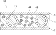
- FIG. 3 is a cross-sectional view schematically showing a PDLC-type light control laminate using adhesive particles according to the first embodiment of the present invention.
- FIG. 4 is a cross-sectional view schematically showing an SPD-type light control laminate using adhesive particles according to the first embodiment of the present invention. 3 and 4, the size, thickness, shape and amount of addition of the light modulating layer and the adhesive particles are appropriately changed from the actual size and shape for convenience of illustration.
- the light modulating layer 4 is sandwiched between the first base material 2 and the second base material 3 .
- the light control layer 4 is arranged between the first base material 2 and the second base material 3 .
- a sealant may be arranged around the light control layer 4 .
- the light control layer 4 includes spacer particles 1X, liquid crystal capsules 4A, and binders 4B.
- the liquid crystal capsule 4A is a liquid crystal material.
- the liquid crystal capsules 4A are dispersed in the binder 4B.
- the liquid crystal capsule 4A is held in a capsule shape in the binder 4B.
- the liquid crystal material may be encapsulated and dispersed in the binder, or the liquid crystal material may be dispersed in the binder as a continuous phase.
- the spacer particles 1X are in contact with the first base material 2 and the second base material 3.
- the spacer particles 1X control the gap between the first base material 2 and the second base material 3.
- the spacer particles 1X contain a compound having a structural unit represented by formula (11) above.
- the material of the spacer particles 1X contains the adhesive particles described above.
- Electrodes are formed on the surface of the first base material 2 and on the surface of the second base material 3 (not shown). Examples of materials for the electrodes include indium tin oxide (ITO). The electrodes are preferably transparent electrodes.
- the orientation of the liquid crystal molecules in the liquid crystal capsule 4A is not uniform. It scatters in the binder and becomes opaque.
- the liquid crystal molecules in the liquid crystal capsule 4A are aligned in a direction parallel to the electric field.
- the binder 4B and the liquid crystal material have the same refractive index, light can be transmitted therethrough, resulting in a transparent state.
- the light modulating layer 5 is sandwiched between the first substrate 2 and the second substrate 3 .
- the light control layer 5 is arranged between the first base material 2 and the second base material 3 .
- the light control layer 5 includes spacer particles 1X, light control suspension liquid droplets 5A, and a resin matrix 5B. Droplets 5A of light conditioning suspension are dispersed in a resin matrix 5B. The droplets 5A of the light control suspension are held in a droplet state in the resin matrix 5B.
- the droplets 5A of the light adjusting suspension contain the dispersion medium 5Aa and the light adjusting particles 5Ab.
- the light adjusting particles 5Ab are dispersed in the dispersion medium 5Aa.
- the spacer particles 1X are in contact with the first base material 2 and the second base material 3.
- the spacer particles 1X control the gap between the first base material 2 and the second base material 3.
- the spacer particles 1X contain a compound having a structural unit represented by formula (11) above.
- the material of the spacer particles 1X contains the adhesive particles described above.
- Electrodes are formed on the surface of the first base material 2 and on the surface of the second base material 3 (not shown). Examples of materials for the electrodes include indium tin oxide (ITO). The electrodes are preferably transparent electrodes.
- the light adjustment particles 5Ab are arranged in a direction parallel to the electric field. Therefore, the incident light can pass between the arranged light adjusting particles 5Ab and can be transmitted through the light adjusting layer 5.
- the light control layer preferably has light control properties. Dimmability is a property that the visible light transmittance changes depending on whether or not an electric field is applied, and the amount of incident light can be adjusted.
- the light control layer includes the spacer particles.
- the light modulating layer preferably further includes a binder and a liquid crystal material dispersed in the binder.
- the liquid crystal material is not particularly limited, and may be any liquid crystal material as long as it has the property of changing its orientation when an electric field is applied.
- the liquid crystal material may be dispersed in the binder as a continuous phase, or may be dispersed in the binder in the form of liquid crystal drops or liquid crystal capsules.
- Examples of the liquid crystal material include nematic liquid crystal and cholesteric liquid crystal.
- nematic liquid crystal Materials for the nematic liquid crystal include cyanobiphenyl, phenyl ester, azoxybenzene, fluorine-containing biphenyl, carbonate, and Schiff base materials. Only one kind of the nematic liquid crystal material may be used, or two or more kinds thereof may be used in combination.
- Materials for the cholesteric liquid crystal include steroidal cholesterol derivatives, Schiff bases, azos, azoxys, benzoates, biphenyls, terphenyls, cyclohexylcarboxylates, phenylcyclohexanes, biphenylcyclohexanes, and pyrimidines.
- cholesteric liquid crystal material Only one kind of the cholesteric liquid crystal material may be used, or two or more kinds thereof may be used in combination.
- the binder holds the liquid crystal material and suppresses the flow of the liquid crystal material.
- the binder is not particularly limited as long as it does not dissolve in the liquid crystal material, has strength to withstand external force, and has high transparency to reflected light and incident light.
- the binder material include water-soluble polymer materials such as gelatin, polyvinyl alcohol, cellulose derivatives, polyacrylic acid-based polymers, ethyleneimine, polyethylene oxide, polyacrylamide, polystyrene sulfonate, polyamidine, isoprene-based sulfonic acid polymers, and materials capable of forming an aqueous emulsion such as fluorine resin, silicone resin, acrylic resin, urethane resin, and epoxy resin. Only one kind of the binder material may be used, or two or more kinds thereof may be used in combination.
- the binder is preferably crosslinked with a crosslinking agent.
- the cross-linking agent is not particularly limited as long as it forms cross-links between the binders and hardens the binder, makes it insoluble, or makes it insoluble.
- Examples of the cross-linking agent include acetaldehyde, glutaraldehyde, glyoxal, potassium alum hydrate of a polyvalent metal salt compound, adipic acid dihydrazide, melamine formalin oligomer, ethylene glycol diglycidyl ether, polyamide epichlorohydrin, and polycarbodiimide. mentioned. Only one kind of the crosslinking agent may be used, or two or more kinds thereof may be used in combination.
- the light control layer further comprises a resin matrix and a light control suspension dispersed in the resin matrix.
- the light control suspension contains a dispersion medium and light control particles dispersed in the dispersion medium.
- the light adjusting particles include carbon-based materials such as polyiodide and carbon black, metal materials such as copper, nickel, iron, cobalt, chromium, titanium, and aluminum, and inorganic compound materials such as silicon nitride, titanium nitride, and aluminum oxide. etc. Also, these materials may be particles coated with a polymer. Only one type of the light adjusting particles may be used, or two or more types may be used in combination.
- the dispersion medium disperses the light adjustment particles in a fluid state.
- the dispersion medium selectively adheres to the light control particles, coats the light control particles, and causes the light control particles to migrate to the phase-separated droplet phase upon phase separation from the resin matrix.
- It is preferably a material that is functional, non-electrically conductive, and incompatible with the resin matrix.
- the dispersion medium is preferably a liquid copolymer having a refractive index similar to that of the resin matrix when the light control laminate is formed.
- a (meth)acrylic ester oligomer having a fluoro group or a hydroxyl group is preferable, and a (meth)acrylic ester oligomer having a fluoro group and a hydroxyl group is more preferable.
- the fluoro or hydroxyl monomer units are oriented toward the light modulating particles and the remaining monomer units stabilize the droplets of the light modulating suspension in the resin matrix. Therefore, the light control particles are easily dispersed in the light control suspension, and the light control particles are easily guided into the phase-separated droplets during phase separation from the resin matrix.
- Examples of the (meth)acrylic acid ester oligomer having a fluoro group or a hydroxyl group include 2,2,2-trifluoroethyl methacrylate/butyl acrylate/2-hydroxyethyl acrylate copolymer, and 3,5,5 acrylic acid.
- the weight average molecular weight of the (meth)acrylate oligomer is preferably 1000 or more, more preferably 2000 or more, and preferably 20000 or less, more preferably 10000 or less.
- the light control layer can be produced using the resin material for forming the resin matrix and the light control suspension.
- the resin material is preferably a resin material that cures when irradiated with energy rays.
- resin materials that are cured by irradiation with energy rays include polymer compositions that contain photopolymerization initiators and polymer compounds that are cured by energy rays such as ultraviolet rays, visible rays, and electron beams.
- the polymer composition include a polymer composition containing a polymerizable monomer having an ethylenically unsaturated group and a photopolymerization initiator.
- the polymerizable monomer having an ethylenically unsaturated group include non-crosslinkable monomers and crosslinkable monomers.
- non-crosslinkable monomers examples include vinyl compounds such as styrene monomers such as styrene, ⁇ -methylstyrene, and chlorostyrene; vinyl ether compounds such as methyl vinyl ether, ethyl vinyl ether, and propyl vinyl ether; vinyl acetate, vinyl butyrate, Acid vinyl ester compounds such as vinyl laurate and vinyl stearate; halogen-containing monomers such as vinyl chloride and vinyl fluoride; ) Alkyl ( meth) acrylate compounds; oxygen atom-containing (meth) acrylate compounds such as 2-hydroxyethyl (meth) acrylate, glycerol (meth) acrylate, polyoxyethylene (meth) acrylate, glycidyl (meth) acrylate; (meth) acrylonitrile and the like Nitrile-containing monomers; halogen-containing (meth)acrylate compounds such as trifluoromethyl (meth)acrylate and pentafluor
- crosslinkable monomers examples include vinyl monomers such as divinylbenzene, 1,4-divinyloxybutane and divinylsulfone as vinyl compounds; and tetramethylolmethane tetra(meth)acrylate as (meth)acrylic compounds.
- polytetramethylene glycol diacrylate tetramethylolmethane tri(meth)acrylate, tetramethylolmethane di(meth)acrylate, trimethylolpropane tri(meth)acrylate, dipentaerythritol hexa(meth)acrylate, dipentaerythritol penta(meth)acrylate ) acrylate, glycerol tri(meth)acrylate, glycerol di(meth)acrylate, polyethylene glycol di(meth)acrylate, polypropylene glycol di(meth)acrylate, polytetramethylene glycol di(meth)acrylate, 1,3-butylene glycol di(meth)acrylate Polyfunctional (meth)acrylate compounds such as (meth)acrylate, 1,4-butanediol di(meth)acrylate, 1,6-hexanediol di(meth)acrylate, 1,9-nonaned
- photopolymerization initiator examples include 2,2-dimethoxy-1,2-diphenylethan-1-one, 1-(4-(2-hydroxyethoxy)phenyl)-2-hydroxy-2-methyl-1-propane -1-one, bis(2,4,6-trimethylbenzoyl)phenylphosphine oxide, 2-hydroxy-2-methyl-1-phenylpropan-1-one, and (1-hydroxycyclohexyl)phenylketone. be done.
- the resin material may contain organic solvent-soluble resin, thermoplastic resin, poly(meth)acrylic acid, and the like.
- the resin material may contain various additives such as an anti-coloring agent, an antioxidant, and an adhesion imparting agent, and may contain a solvent.
- the first substrate is preferably a transparent substrate.
- the second base material is preferably a transparent base material.
- the transparent substrate is, for example, a substrate having optical transparency (light transmissive substrate). For example, light is transmitted from one side of the transparent substrate to the other side through the transparent substrate. For example, when viewing a substance on the other side through the transparent substrate from one side of the transparent substrate, the substance can be visually recognized. Transparency also includes translucence, for example.
- the transparent substrate may be colorless and transparent, or may be colored and transparent.
- the materials of the first base material and the second base material are not particularly limited.
- the material of the first base material and the material of the second base material may be the same or different.
- materials for the first base material and the second base material include glass and resin films.
- the glass include soda-lime glass, lead glass, borosilicate glass for general construction, glasses of various compositions for other applications, and functional glasses such as heat-reflecting glass, heat-absorbing glass, and tempered glass.
- the resin film include polyester films such as polyethylene terephthalate, polyolefin films such as polypropylene, and resin films such as acrylic resin films.
- the first substrate and the second substrate are preferably resin substrates, more preferably resin films, because they are excellent in transparency, moldability, adhesiveness, processability, and the like. , more preferably a polyethylene terephthalate (PET) film.
- PET polyethylene terephthalate
- the first base material and the second base material may include a base body and a conductive film formed on the surface of the base body so that an electric field for dimming can be applied.
- the conductive film include indium tin oxide (ITO), SnO 2 and In 2 O 3 .
- the conductive film is preferably a transparent conductive film.
- the visible light transmittance of the first base material and the second base material is preferably 75% or more, more preferably 80% or more.
- the visible light transmittance of the first base material and the second base material can be measured in accordance with ISO13837:2008 by carrying out spectrometry or the like.
- Base particles A (acrylic-divinylbenzene copolymer particles, average particle size 15.0 ⁇ m, prepared according to Synthesis Example 1 below)
- Base particles B carbon black-dispersed acrylic-divinylbenzene copolymer particles, average particle size 18.0 ⁇ m, prepared according to Synthesis Example 2 below)
- Base particles C (acrylic-divinylbenzene copolymer particles, average particle size 15.0 ⁇ m, prepared according to Synthesis Example 3 below)
- Base particle D (“Micropearl SP-215" manufactured by Sekisui Chemical Co., Ltd., average particle size 15.0 ⁇ m)
- Substrate particles E (silicone particles, average particle size 16.0 ⁇ m, prepared according to Synthesis Example 4 below)
- Base particles F (acrylic-divinylbenzene copolymer particles, average particle size 20.0 ⁇ m, prepared according to Synthesis Example 5 below)
- Base particles G (“Micropearl SP-220” manufactured by Sekisui Chemical
- Synthesis example 1 Polystyrene particles having an average particle size of 5.0 ⁇ m were prepared as seed particles. 3.5 parts by weight of the above polystyrene particles, 500 parts by weight of ion-exchanged water, and 120 parts by weight of a 5% by weight aqueous solution of polyvinyl alcohol were mixed to prepare a mixed solution. After ultrasonically dispersing the mixed liquid, the mixed liquid was placed in a separable flask and uniformly stirred.
- Synthesis example 2 Polystyrene particles having an average particle size of 5.0 ⁇ m were prepared as seed particles. 3.5 parts by weight of the above polystyrene particles, 500 parts by weight of ion-exchanged water, and 120 parts by weight of a 5% by weight aqueous solution of polyvinyl alcohol were mixed to prepare a mixed solution. After ultrasonically dispersing the mixed liquid, the mixed liquid was placed in a separable flask and uniformly stirred.
- the emulsified liquid was added in two portions to the mixed liquid in the separable flask and stirred for 8 hours to allow the seed particles to absorb the monomer, thereby obtaining a suspension containing seed particles in which the monomer was swollen. . After that, 400 parts by weight of a 5% by weight aqueous solution of polyvinyl alcohol was added, and heating was started to react at 85° C. for 11 hours to obtain particles. The obtained particles were purified to obtain substrate particles B by a classification operation.
- the aqueous solution B was added. After that, emulsification was performed using a Shirasu Porous Glass (SPG) membrane (average pore size: about 20 ⁇ m). After that, the temperature was raised to 85° C. and polymerization was carried out for 9 hours. The whole amount of the polymerized particles was washed with water by centrifugation, classified, and freeze-dried to obtain substrate particles E.
- SPG Shirasu Porous Glass
- Polystyrene particles having an average particle size of 5.0 ⁇ m were prepared as seed particles. 3.5 parts by weight of the above polystyrene particles, 500 parts by weight of ion-exchanged water, and 120 parts by weight of a 5% by weight aqueous solution of polyvinyl alcohol were mixed to prepare a mixed solution. After ultrasonically dispersing the mixed liquid, the mixed liquid was placed in a separable flask and uniformly stirred.
- Thermosetting resin Epoxy resin (equal mixture of "EPICLON-EXA-850CRP” manufactured by DIC and "EPICLON-EXA-4850-150” manufactured by DIC) Polyamide resin ("Aronmighty FS-1750SV10" manufactured by Toagosei Co., Ltd.)
- Curing agent I amine curing agent, "Norbornanediamine” manufactured by Mitsui Chemicals Fine Co., Ltd.
- Curing agent II aromatic amine curing agent, "4,4'-diaminodiphenylmethane” manufactured by Tokyo Chemical Industry Co., Ltd.
- a compound having a structure represented by the above formula (1) Compound A ("X-22-163" manufactured by Shin-Etsu Silicone Co., Ltd.)
- Adhesive particles were produced in the same manner as in Example 1, except that the type of substrate particles and the structure of the coating portion were changed as shown in Tables 1-4.
- Example 10 3 parts by weight of base particles C, 15 parts by weight of polyamide resin, 4.8 parts by weight of cetyltrimethylammonium bromide as a dispersion stabilizer, and 100 parts by weight of ethanol were placed in a reaction vessel equipped with a thermometer, a stirrer and a cooling tube. was added and uniformly dissolved by stirring at 25° C. for 1 hour. Next, 1000 parts by weight of a 5% by weight aqueous solution of polyvinyl alcohol was added to the container to obtain a composite of the substrate particles and the polyamide resin. After freeze-drying the resulting composite, a classification operation was performed to recover the adhesive particles.
- a light control film was prepared in which a known SPD layer was arranged between two sheets of PET film on which transparent and conductive ITO was vapor-deposited, except that 5% by weight of the obtained adhesive particles were dispersed.
- the light control film was sandwiched between two sheets of transparent glass, a weight of 5 kg was placed, and the film was placed on a hot plate and heated at 120° C. for 1 hour to bond the upper and lower substrates.
- sandwiching the light control film between two sheets of transparent glass an SPD type light control laminate in which spacer particles are adhered to the first and second substrates was produced.
- a light control film was prepared by disposing a known PDLC layer between two sheets of PET film on which transparent and conductive ITO was vapor-deposited, except that 5% by weight of the obtained adhesive particles were dispersed.
- the light control film was sandwiched between two sheets of transparent glass, a weight of 5 kg was placed, and the film was placed on a hot plate and heated at 120° C. for 1 hour to bond the upper and lower substrates.
- a PDLC type light control laminate in which spacer particles are adhered to the first and second substrates was produced.
- Average Particle Size About 100,000 particles of the obtained adhesive particles were measured for particle size using a particle size distribution analyzer (“Multisizer 4” manufactured by Beckman Coulter, Inc.) to measure the average particle size.
- Adhesion tensile yield stress
- a test body test sample was prepared according to the above-described adhesion test A.
- Tensilon universal material testing machine RTI-1310 manufactured by A&D was used to measure the tensile yield stress of the specimen at 23°C (adhesion test A).
- Adhesion (tensile yield stress) was determined according to the following criteria.
- Tensile yield stress is 0.12 MPa or more
- Tensile yield stress is 0.10 MPa or more and less than 0.12 MPa
- Tensile yield stress is 0.07 MPa or more and less than 0.10 MPa
- Tensile yield stress is 0.07 MPa less than
- Adhesiveness (90° peel strength) Using the obtained adhesive particles, a test body (test sample) was prepared according to the above-described adhesion test B. In accordance with JIS K6854: 1999, using a tensile tester ("Autograph AGS" manufactured by Shimadzu Corporation), the 90 ° peel strength at 23 ° C. of the above test body was measured at a tensile speed of 50 mm / sec (adhesion sex test B). Adhesiveness (90° peel strength) was judged according to the following criteria.
- 90° peel strength is 1.0 N/30 mm or more ⁇ : 90° peel strength is 0.5 N/30 mm or more and less than 1.0 N/30 mm ⁇ : 90° peel strength is 0.1 N/30 mm or more, 0. Less than 5N/30mm x: 90° peel strength less than 0.1N/30mm
- the obtained light control laminate was curved using a cylindrical plate having a curvature of 0.1 to obtain a light control laminate having a curved surface portion.
- VHX-2000 manufactured by Keyence Corporation
- the number of remaining spacer particles was counted in five arbitrary 1 cm 2 regions on the surface of the second substrate. The standard deviation of the number of remaining spacer particles was determined, and the survivability of the spacer particles was judged according to the following criteria.
- Standard deviation is less than 2 ⁇ : Standard deviation is 2 or more and less than 4 ⁇ : Standard deviation is 4 or more and less than 6 ⁇ : Standard deviation is 6 or more
- the obtained light control laminate was curved using a cylindrical plate having a curvature of 0.1 to obtain a light control laminate having a curved surface portion.
- the thickness of the light modulating layer of the light modulating laminate was measured using a scanning electron microscope.
- the ratio of the minimum thickness of the light control layer to the maximum thickness of the light control layer was calculated, and the gap controllability was calculated as follows. Judged by the standard.
- composition and results of the adhesive particles are shown in Tables 1 to 4 below.
Landscapes
- Chemical & Material Sciences (AREA)
- Organic Chemistry (AREA)
- Physics & Mathematics (AREA)
- Chemical Kinetics & Catalysis (AREA)
- Medicinal Chemistry (AREA)
- Polymers & Plastics (AREA)
- Health & Medical Sciences (AREA)
- Nonlinear Science (AREA)
- General Physics & Mathematics (AREA)
- Optics & Photonics (AREA)
- Crystallography & Structural Chemistry (AREA)
- Mathematical Physics (AREA)
- Inorganic Chemistry (AREA)
- Adhesives Or Adhesive Processes (AREA)
- Laminated Bodies (AREA)
Priority Applications (5)
| Application Number | Priority Date | Filing Date | Title |
|---|---|---|---|
| CN202280071262.XA CN118159901A (zh) | 2021-11-22 | 2022-11-22 | 粘接性粒子和叠层体 |
| EP22895738.7A EP4439162A4 (en) | 2021-11-22 | 2022-11-22 | ADHESIVE PARTICLES AND LAMINATE |
| KR1020247016034A KR20240102972A (ko) | 2021-11-22 | 2022-11-22 | 접착성 입자 및 적층체 |
| JP2022573500A JPWO2023090457A1 (https=) | 2021-11-22 | 2022-11-22 | |
| US18/711,724 US20250011635A1 (en) | 2021-11-22 | 2022-11-22 | Adhesive particles and laminate |
Applications Claiming Priority (2)
| Application Number | Priority Date | Filing Date | Title |
|---|---|---|---|
| JP2021189156 | 2021-11-22 | ||
| JP2021-189156 | 2021-11-22 |
Publications (1)
| Publication Number | Publication Date |
|---|---|
| WO2023090457A1 true WO2023090457A1 (ja) | 2023-05-25 |
Family
ID=86397189
Family Applications (1)
| Application Number | Title | Priority Date | Filing Date |
|---|---|---|---|
| PCT/JP2022/043163 Ceased WO2023090457A1 (ja) | 2021-11-22 | 2022-11-22 | 接着性粒子及び積層体 |
Country Status (7)
| Country | Link |
|---|---|
| US (1) | US20250011635A1 (https=) |
| EP (1) | EP4439162A4 (https=) |
| JP (1) | JPWO2023090457A1 (https=) |
| KR (1) | KR20240102972A (https=) |
| CN (1) | CN118159901A (https=) |
| TW (1) | TW202335853A (https=) |
| WO (1) | WO2023090457A1 (https=) |
Families Citing this family (2)
| Publication number | Priority date | Publication date | Assignee | Title |
|---|---|---|---|---|
| CN118159902A (zh) * | 2021-11-22 | 2024-06-07 | 积水化学工业株式会社 | 粘接性粒子和叠层体 |
| CN119348260B (zh) * | 2024-09-11 | 2025-10-14 | 杭州诗蓝过滤科技有限公司 | 一种超柔透气防水膜及其制备方法 |
Citations (6)
| Publication number | Priority date | Publication date | Assignee | Title |
|---|---|---|---|---|
| JP2007156319A (ja) * | 2005-12-08 | 2007-06-21 | Sekisui Chem Co Ltd | 強固着性液晶スペーサの製造方法、強固着性液晶スペーサ、スペーサ分散液及び液晶表示装置 |
| WO2016181860A1 (ja) * | 2015-05-08 | 2016-11-17 | 積水化学工業株式会社 | シリコーン粒子、シリコーン粒子の製造方法、液晶滴下工法用シール剤及び液晶表示素子 |
| JP2016218257A (ja) | 2015-05-20 | 2016-12-22 | 積水化学工業株式会社 | 液晶滴下工法用シール剤に用いる硬化性樹脂粒子、液晶滴下工法用シール剤及び液晶表示素子 |
| WO2018016378A1 (ja) * | 2016-07-19 | 2018-01-25 | 積水化学工業株式会社 | 調光積層体及び調光積層体用樹脂スペーサ |
| JP2018132740A (ja) | 2017-02-17 | 2018-08-23 | 積水化学工業株式会社 | 粒子及び液晶表示素子 |
| WO2018203500A1 (ja) * | 2017-05-01 | 2018-11-08 | 積水化学工業株式会社 | 樹脂粒子、接続材料及び接続構造体 |
Family Cites Families (4)
| Publication number | Priority date | Publication date | Assignee | Title |
|---|---|---|---|---|
| JP3832777B2 (ja) * | 1996-08-12 | 2006-10-11 | 宇部日東化成株式会社 | エポキシ樹脂被覆熱接着性粒子の製造方法 |
| US20090033859A1 (en) * | 2005-06-21 | 2009-02-05 | Michihisa Ueda | Liquid Crystal Spacer, Spacer Diffusion Liquid, Liquid Crystal Display Device Manufacturing Method, and Liquid Crystal Display Device |
| JP7411386B2 (ja) * | 2019-11-07 | 2024-01-11 | 信越化学工業株式会社 | エポキシ変性シリコーン微粒子及びその製造方法、並びに該微粒子を含有する熱硬化性樹脂組成物及び封止材 |
| CN118159902A (zh) * | 2021-11-22 | 2024-06-07 | 积水化学工业株式会社 | 粘接性粒子和叠层体 |
-
2022
- 2022-11-22 KR KR1020247016034A patent/KR20240102972A/ko not_active Withdrawn
- 2022-11-22 CN CN202280071262.XA patent/CN118159901A/zh active Pending
- 2022-11-22 JP JP2022573500A patent/JPWO2023090457A1/ja not_active Withdrawn
- 2022-11-22 TW TW111144636A patent/TW202335853A/zh unknown
- 2022-11-22 WO PCT/JP2022/043163 patent/WO2023090457A1/ja not_active Ceased
- 2022-11-22 US US18/711,724 patent/US20250011635A1/en active Pending
- 2022-11-22 EP EP22895738.7A patent/EP4439162A4/en active Pending
Patent Citations (6)
| Publication number | Priority date | Publication date | Assignee | Title |
|---|---|---|---|---|
| JP2007156319A (ja) * | 2005-12-08 | 2007-06-21 | Sekisui Chem Co Ltd | 強固着性液晶スペーサの製造方法、強固着性液晶スペーサ、スペーサ分散液及び液晶表示装置 |
| WO2016181860A1 (ja) * | 2015-05-08 | 2016-11-17 | 積水化学工業株式会社 | シリコーン粒子、シリコーン粒子の製造方法、液晶滴下工法用シール剤及び液晶表示素子 |
| JP2016218257A (ja) | 2015-05-20 | 2016-12-22 | 積水化学工業株式会社 | 液晶滴下工法用シール剤に用いる硬化性樹脂粒子、液晶滴下工法用シール剤及び液晶表示素子 |
| WO2018016378A1 (ja) * | 2016-07-19 | 2018-01-25 | 積水化学工業株式会社 | 調光積層体及び調光積層体用樹脂スペーサ |
| JP2018132740A (ja) | 2017-02-17 | 2018-08-23 | 積水化学工業株式会社 | 粒子及び液晶表示素子 |
| WO2018203500A1 (ja) * | 2017-05-01 | 2018-11-08 | 積水化学工業株式会社 | 樹脂粒子、接続材料及び接続構造体 |
Non-Patent Citations (1)
| Title |
|---|
| See also references of EP4439162A4 |
Also Published As
| Publication number | Publication date |
|---|---|
| TW202335853A (zh) | 2023-09-16 |
| EP4439162A4 (en) | 2025-11-12 |
| US20250011635A1 (en) | 2025-01-09 |
| EP4439162A1 (en) | 2024-10-02 |
| CN118159901A (zh) | 2024-06-07 |
| JPWO2023090457A1 (https=) | 2023-05-25 |
| KR20240102972A (ko) | 2024-07-03 |
Similar Documents
| Publication | Publication Date | Title |
|---|---|---|
| TWI832804B (zh) | 調光積層體及調光積層體用樹脂間隔件 | |
| JP2023112207A (ja) | 調光積層体及び調光積層体用樹脂スペーサ | |
| WO2023090457A1 (ja) | 接着性粒子及び積層体 | |
| WO2023090456A1 (ja) | 接着性粒子及び積層体 | |
| JP2025041960A (ja) | 着色樹脂粒子及び調光積層体 | |
| JP7534909B2 (ja) | 調光積層体 | |
| JP7755568B2 (ja) | 接着性粒子、接着剤及び調光積層体 | |
| CN116601000B (zh) | 粘接性粒子、粘接剂及调光叠层体 | |
| TWI908950B (zh) | 接著性粒子、接著劑及調光積層體 | |
| JP7579361B2 (ja) | 着色樹脂粒子及び調光積層体 | |
| JP7198668B2 (ja) | 複合粒子、複合粒子粉体及び調光材 |
Legal Events
| Date | Code | Title | Description |
|---|---|---|---|
| WWE | Wipo information: entry into national phase |
Ref document number: 2022573500 Country of ref document: JP |
|
| 121 | Ep: the epo has been informed by wipo that ep was designated in this application |
Ref document number: 22895738 Country of ref document: EP Kind code of ref document: A1 |
|
| WWE | Wipo information: entry into national phase |
Ref document number: 202280071262.X Country of ref document: CN |
|
| WWE | Wipo information: entry into national phase |
Ref document number: 18711724 Country of ref document: US |
|
| WWE | Wipo information: entry into national phase |
Ref document number: 2022895738 Country of ref document: EP |
|
| NENP | Non-entry into the national phase |
Ref country code: DE |
|
| ENP | Entry into the national phase |
Ref document number: 2022895738 Country of ref document: EP Effective date: 20240624 |