WO2023090457A1 - Adhesive particles and laminate - Google Patents
Adhesive particles and laminate Download PDFInfo
- Publication number
- WO2023090457A1 WO2023090457A1 PCT/JP2022/043163 JP2022043163W WO2023090457A1 WO 2023090457 A1 WO2023090457 A1 WO 2023090457A1 JP 2022043163 W JP2022043163 W JP 2022043163W WO 2023090457 A1 WO2023090457 A1 WO 2023090457A1
- Authority
- WO
- WIPO (PCT)
- Prior art keywords
- particles
- group
- substrate
- adhesive particles
- laminate
- Prior art date
Links
- 239000002245 particle Substances 0.000 title claims abstract description 442
- 239000000853 adhesive Substances 0.000 title claims abstract description 171
- 230000001070 adhesive effect Effects 0.000 title claims abstract description 171
- 239000000463 material Substances 0.000 claims abstract description 152
- 229920005989 resin Polymers 0.000 claims abstract description 56
- 239000011347 resin Substances 0.000 claims abstract description 56
- 229910052700 potassium Inorganic materials 0.000 claims abstract description 38
- 229920001187 thermosetting polymer Polymers 0.000 claims abstract description 30
- 239000000758 substrate Substances 0.000 claims description 143
- 150000001875 compounds Chemical class 0.000 claims description 67
- 125000006850 spacer group Chemical group 0.000 claims description 64
- 125000004432 carbon atom Chemical group C* 0.000 claims description 44
- 239000011248 coating agent Substances 0.000 claims description 35
- 238000000576 coating method Methods 0.000 claims description 35
- 239000003822 epoxy resin Substances 0.000 claims description 32
- 125000000962 organic group Chemical group 0.000 claims description 32
- 229920000647 polyepoxide Polymers 0.000 claims description 32
- 125000000391 vinyl group Chemical group [H]C([*])=C([H])[H] 0.000 claims description 32
- 238000007906 compression Methods 0.000 claims description 29
- 230000006835 compression Effects 0.000 claims description 26
- 238000010438 heat treatment Methods 0.000 claims description 25
- 125000000217 alkyl group Chemical group 0.000 claims description 24
- 125000003545 alkoxy group Chemical group 0.000 claims description 22
- 238000011084 recovery Methods 0.000 claims description 20
- 125000004435 hydrogen atom Chemical group [H]* 0.000 claims description 12
- 125000002887 hydroxy group Chemical group [H]O* 0.000 claims description 11
- 125000003277 amino group Chemical group 0.000 claims description 7
- 125000003700 epoxy group Chemical group 0.000 claims description 7
- 125000003368 amide group Chemical group 0.000 claims description 6
- IQPQWNKOIGAROB-UHFFFAOYSA-N isocyanate group Chemical group [N-]=C=O IQPQWNKOIGAROB-UHFFFAOYSA-N 0.000 claims description 6
- 230000002708 enhancing effect Effects 0.000 abstract description 10
- 239000002585 base Substances 0.000 description 102
- NIXOWILDQLNWCW-UHFFFAOYSA-M Acrylate Chemical compound [O-]C(=O)C=C NIXOWILDQLNWCW-UHFFFAOYSA-M 0.000 description 44
- 239000010410 layer Substances 0.000 description 43
- 238000001723 curing Methods 0.000 description 41
- 239000003795 chemical substances by application Substances 0.000 description 40
- -1 polyethylene Polymers 0.000 description 37
- 239000000178 monomer Substances 0.000 description 36
- 239000004973 liquid crystal related substance Substances 0.000 description 32
- 238000000034 method Methods 0.000 description 24
- MYRTYDVEIRVNKP-UHFFFAOYSA-N 1,2-Divinylbenzene Chemical compound C=CC1=CC=CC=C1C=C MYRTYDVEIRVNKP-UHFFFAOYSA-N 0.000 description 22
- 239000000047 product Substances 0.000 description 22
- 229920001577 copolymer Polymers 0.000 description 21
- 238000012360 testing method Methods 0.000 description 21
- PEDCQBHIVMGVHV-UHFFFAOYSA-N Glycerine Chemical compound OCC(O)CO PEDCQBHIVMGVHV-UHFFFAOYSA-N 0.000 description 20
- 239000011230 binding agent Substances 0.000 description 19
- 239000011521 glass Substances 0.000 description 17
- 239000007788 liquid Substances 0.000 description 17
- 239000000725 suspension Substances 0.000 description 14
- 238000006073 displacement reaction Methods 0.000 description 12
- 239000011159 matrix material Substances 0.000 description 12
- 229920000642 polymer Polymers 0.000 description 12
- 239000007864 aqueous solution Substances 0.000 description 11
- 230000015572 biosynthetic process Effects 0.000 description 11
- LNEPOXFFQSENCJ-UHFFFAOYSA-N haloperidol Chemical compound C1CC(O)(C=2C=CC(Cl)=CC=2)CCN1CCCC(=O)C1=CC=C(F)C=C1 LNEPOXFFQSENCJ-UHFFFAOYSA-N 0.000 description 11
- 238000003786 synthesis reaction Methods 0.000 description 11
- 239000004983 Polymer Dispersed Liquid Crystal Substances 0.000 description 10
- 230000005684 electric field Effects 0.000 description 10
- 239000004372 Polyvinyl alcohol Substances 0.000 description 9
- 150000001252 acrylic acid derivatives Chemical class 0.000 description 9
- CQEYYJKEWSMYFG-UHFFFAOYSA-N butyl acrylate Chemical compound CCCCOC(=O)C=C CQEYYJKEWSMYFG-UHFFFAOYSA-N 0.000 description 9
- 239000002775 capsule Substances 0.000 description 9
- 239000002612 dispersion medium Substances 0.000 description 9
- LYCAIKOWRPUZTN-UHFFFAOYSA-N ethylene glycol Natural products OCCO LYCAIKOWRPUZTN-UHFFFAOYSA-N 0.000 description 9
- RAXXELZNTBOGNW-UHFFFAOYSA-N imidazole Natural products C1=CNC=N1 RAXXELZNTBOGNW-UHFFFAOYSA-N 0.000 description 9
- 238000006116 polymerization reaction Methods 0.000 description 9
- 229920002451 polyvinyl alcohol Polymers 0.000 description 9
- LFQSCWFLJHTTHZ-UHFFFAOYSA-N Ethanol Chemical compound CCO LFQSCWFLJHTTHZ-UHFFFAOYSA-N 0.000 description 8
- PPBRXRYQALVLMV-UHFFFAOYSA-N Styrene Chemical compound C=CC1=CC=CC=C1 PPBRXRYQALVLMV-UHFFFAOYSA-N 0.000 description 8
- 150000008065 acid anhydrides Chemical class 0.000 description 8
- 150000001412 amines Chemical class 0.000 description 8
- 125000002496 methyl group Chemical group [H]C([H])([H])* 0.000 description 8
- 238000000926 separation method Methods 0.000 description 8
- XLYOFNOQVPJJNP-UHFFFAOYSA-N water Substances O XLYOFNOQVPJJNP-UHFFFAOYSA-N 0.000 description 8
- 239000004793 Polystyrene Substances 0.000 description 7
- 235000011187 glycerol Nutrition 0.000 description 7
- 238000005192 partition Methods 0.000 description 7
- 229920002223 polystyrene Polymers 0.000 description 7
- 229920002545 silicone oil Polymers 0.000 description 7
- RRHGJUQNOFWUDK-UHFFFAOYSA-N Isoprene Chemical compound CC(=C)C=C RRHGJUQNOFWUDK-UHFFFAOYSA-N 0.000 description 6
- OKKJLVBELUTLKV-UHFFFAOYSA-N Methanol Chemical compound OC OKKJLVBELUTLKV-UHFFFAOYSA-N 0.000 description 6
- 238000009826 distribution Methods 0.000 description 6
- 229910010272 inorganic material Inorganic materials 0.000 description 6
- 239000000203 mixture Substances 0.000 description 6
- 239000011368 organic material Substances 0.000 description 6
- 229940059574 pentaerithrityl Drugs 0.000 description 6
- WXZMFSXDPGVJKK-UHFFFAOYSA-N pentaerythritol Chemical compound OCC(CO)(CO)CO WXZMFSXDPGVJKK-UHFFFAOYSA-N 0.000 description 6
- 239000003505 polymerization initiator Substances 0.000 description 6
- 239000000243 solution Substances 0.000 description 6
- PSGCQDPCAWOCSH-UHFFFAOYSA-N (4,7,7-trimethyl-3-bicyclo[2.2.1]heptanyl) prop-2-enoate Chemical compound C1CC2(C)C(OC(=O)C=C)CC1C2(C)C PSGCQDPCAWOCSH-UHFFFAOYSA-N 0.000 description 5
- TXBCBTDQIULDIA-UHFFFAOYSA-N 2-[[3-hydroxy-2,2-bis(hydroxymethyl)propoxy]methyl]-2-(hydroxymethyl)propane-1,3-diol Chemical compound OCC(CO)(CO)COCC(CO)(CO)CO TXBCBTDQIULDIA-UHFFFAOYSA-N 0.000 description 5
- 239000004925 Acrylic resin Substances 0.000 description 5
- 229920000178 Acrylic resin Polymers 0.000 description 5
- XMSVKICKONKVNM-UHFFFAOYSA-N bicyclo[2.2.1]heptane-3,4-diamine Chemical compound C1CC2(N)C(N)CC1C2 XMSVKICKONKVNM-UHFFFAOYSA-N 0.000 description 5
- 229910003460 diamond Inorganic materials 0.000 description 5
- 239000010432 diamond Substances 0.000 description 5
- 230000000694 effects Effects 0.000 description 5
- 125000001153 fluoro group Chemical group F* 0.000 description 5
- 230000001965 increasing effect Effects 0.000 description 5
- 239000011147 inorganic material Substances 0.000 description 5
- 229920006122 polyamide resin Polymers 0.000 description 5
- 230000000379 polymerizing effect Effects 0.000 description 5
- 239000000126 substance Substances 0.000 description 5
- KAKZBPTYRLMSJV-UHFFFAOYSA-N Butadiene Chemical compound C=CC=C KAKZBPTYRLMSJV-UHFFFAOYSA-N 0.000 description 4
- CERQOIWHTDAKMF-UHFFFAOYSA-N Methacrylic acid Chemical compound CC(=C)C(O)=O CERQOIWHTDAKMF-UHFFFAOYSA-N 0.000 description 4
- 239000004988 Nematic liquid crystal Substances 0.000 description 4
- NIXOWILDQLNWCW-UHFFFAOYSA-N acrylic acid group Chemical group C(C=C)(=O)O NIXOWILDQLNWCW-UHFFFAOYSA-N 0.000 description 4
- WERYXYBDKMZEQL-UHFFFAOYSA-N butane-1,4-diol Chemical compound OCCCCO WERYXYBDKMZEQL-UHFFFAOYSA-N 0.000 description 4
- 238000006243 chemical reaction Methods 0.000 description 4
- 239000003086 colorant Substances 0.000 description 4
- 239000003431 cross linking reagent Substances 0.000 description 4
- ZUOUZKKEUPVFJK-UHFFFAOYSA-N diphenyl Chemical compound C1=CC=CC=C1C1=CC=CC=C1 ZUOUZKKEUPVFJK-UHFFFAOYSA-N 0.000 description 4
- 239000000839 emulsion Substances 0.000 description 4
- FJKIXWOMBXYWOQ-UHFFFAOYSA-N ethenoxyethane Chemical compound CCOC=C FJKIXWOMBXYWOQ-UHFFFAOYSA-N 0.000 description 4
- ZLNAFSPCNATQPQ-UHFFFAOYSA-N ethenyl-dimethoxy-methylsilane Chemical compound CO[Si](C)(OC)C=C ZLNAFSPCNATQPQ-UHFFFAOYSA-N 0.000 description 4
- 125000001495 ethyl group Chemical group [H]C([H])([H])C([H])([H])* 0.000 description 4
- 229910052736 halogen Inorganic materials 0.000 description 4
- 150000002367 halogens Chemical class 0.000 description 4
- NAQMVNRVTILPCV-UHFFFAOYSA-N hexane-1,6-diamine Chemical compound NCCCCCCN NAQMVNRVTILPCV-UHFFFAOYSA-N 0.000 description 4
- WGCNASOHLSPBMP-UHFFFAOYSA-N hydroxyacetaldehyde Natural products OCC=O WGCNASOHLSPBMP-UHFFFAOYSA-N 0.000 description 4
- 229920000139 polyethylene terephthalate Polymers 0.000 description 4
- 239000005020 polyethylene terephthalate Substances 0.000 description 4
- 238000010526 radical polymerization reaction Methods 0.000 description 4
- 229910000077 silane Inorganic materials 0.000 description 4
- 150000003573 thiols Chemical class 0.000 description 4
- 238000002834 transmittance Methods 0.000 description 4
- GEYOCULIXLDCMW-UHFFFAOYSA-N 1,2-phenylenediamine Chemical compound NC1=CC=CC=C1N GEYOCULIXLDCMW-UHFFFAOYSA-N 0.000 description 3
- LIFHMKCDDVTICL-UHFFFAOYSA-N 6-(chloromethyl)phenanthridine Chemical compound C1=CC=C2C(CCl)=NC3=CC=CC=C3C2=C1 LIFHMKCDDVTICL-UHFFFAOYSA-N 0.000 description 3
- 239000004342 Benzoyl peroxide Substances 0.000 description 3
- OMPJBNCRMGITSC-UHFFFAOYSA-N Benzoylperoxide Chemical compound C=1C=CC=CC=1C(=O)OOC(=O)C1=CC=CC=C1 OMPJBNCRMGITSC-UHFFFAOYSA-N 0.000 description 3
- 229920002799 BoPET Polymers 0.000 description 3
- 239000004986 Cholesteric liquid crystals (ChLC) Substances 0.000 description 3
- WSFSSNUMVMOOMR-UHFFFAOYSA-N Formaldehyde Chemical compound O=C WSFSSNUMVMOOMR-UHFFFAOYSA-N 0.000 description 3
- 229920000877 Melamine resin Polymers 0.000 description 3
- 229920003171 Poly (ethylene oxide) Polymers 0.000 description 3
- 239000002262 Schiff base Substances 0.000 description 3
- 150000004753 Schiff bases Chemical class 0.000 description 3
- ZJCCRDAZUWHFQH-UHFFFAOYSA-N Trimethylolpropane Chemical compound CCC(CO)(CO)CO ZJCCRDAZUWHFQH-UHFFFAOYSA-N 0.000 description 3
- 239000012790 adhesive layer Substances 0.000 description 3
- 150000008064 anhydrides Chemical class 0.000 description 3
- 235000019400 benzoyl peroxide Nutrition 0.000 description 3
- 230000001588 bifunctional effect Effects 0.000 description 3
- 235000010290 biphenyl Nutrition 0.000 description 3
- 239000002270 dispersing agent Substances 0.000 description 3
- MBGQQKKTDDNCSG-UHFFFAOYSA-N ethenyl-diethoxy-methylsilane Chemical compound CCO[Si](C)(C=C)OCC MBGQQKKTDDNCSG-UHFFFAOYSA-N 0.000 description 3
- 239000005357 flat glass Substances 0.000 description 3
- 238000013007 heat curing Methods 0.000 description 3
- AMGQUBHHOARCQH-UHFFFAOYSA-N indium;oxotin Chemical compound [In].[Sn]=O AMGQUBHHOARCQH-UHFFFAOYSA-N 0.000 description 3
- 239000003999 initiator Substances 0.000 description 3
- FPYJFEHAWHCUMM-UHFFFAOYSA-N maleic anhydride Chemical compound O=C1OC(=O)C=C1 FPYJFEHAWHCUMM-UHFFFAOYSA-N 0.000 description 3
- 238000004519 manufacturing process Methods 0.000 description 3
- 239000011259 mixed solution Substances 0.000 description 3
- 238000012643 polycondensation polymerization Methods 0.000 description 3
- 238000006068 polycondensation reaction Methods 0.000 description 3
- 229920001296 polysiloxane Polymers 0.000 description 3
- 229920005992 thermoplastic resin Polymers 0.000 description 3
- VZCYOOQTPOCHFL-UHFFFAOYSA-N trans-butenedioic acid Natural products OC(=O)C=CC(O)=O VZCYOOQTPOCHFL-UHFFFAOYSA-N 0.000 description 3
- SRPWOOOHEPICQU-UHFFFAOYSA-N trimellitic anhydride Chemical compound OC(=O)C1=CC=C2C(=O)OC(=O)C2=C1 SRPWOOOHEPICQU-UHFFFAOYSA-N 0.000 description 3
- PUPZLCDOIYMWBV-UHFFFAOYSA-N (+/-)-1,3-Butanediol Chemical compound CC(O)CCO PUPZLCDOIYMWBV-UHFFFAOYSA-N 0.000 description 2
- LTQBNYCMVZQRSD-UHFFFAOYSA-N (4-ethenylphenyl)-trimethoxysilane Chemical compound CO[Si](OC)(OC)C1=CC=C(C=C)C=C1 LTQBNYCMVZQRSD-UHFFFAOYSA-N 0.000 description 2
- WZCQRUWWHSTZEM-UHFFFAOYSA-N 1,3-phenylenediamine Chemical compound NC1=CC=CC(N)=C1 WZCQRUWWHSTZEM-UHFFFAOYSA-N 0.000 description 2
- MWZJGRDWJVHRDV-UHFFFAOYSA-N 1,4-bis(ethenoxy)butane Chemical compound C=COCCCCOC=C MWZJGRDWJVHRDV-UHFFFAOYSA-N 0.000 description 2
- PWGJDPKCLMLPJW-UHFFFAOYSA-N 1,8-diaminooctane Chemical compound NCCCCCCCCN PWGJDPKCLMLPJW-UHFFFAOYSA-N 0.000 description 2
- OVGRCEFMXPHEBL-UHFFFAOYSA-N 1-ethenoxypropane Chemical compound CCCOC=C OVGRCEFMXPHEBL-UHFFFAOYSA-N 0.000 description 2
- QTKPMCIBUROOGY-UHFFFAOYSA-N 2,2,2-trifluoroethyl 2-methylprop-2-enoate Chemical compound CC(=C)C(=O)OCC(F)(F)F QTKPMCIBUROOGY-UHFFFAOYSA-N 0.000 description 2
- FXNDIJDIPNCZQJ-UHFFFAOYSA-N 2,4,4-trimethylpent-1-ene Chemical group CC(=C)CC(C)(C)C FXNDIJDIPNCZQJ-UHFFFAOYSA-N 0.000 description 2
- SBYMUDUGTIKLCR-UHFFFAOYSA-N 2-chloroethenylbenzene Chemical compound ClC=CC1=CC=CC=C1 SBYMUDUGTIKLCR-UHFFFAOYSA-N 0.000 description 2
- 125000000954 2-hydroxyethyl group Chemical group [H]C([*])([H])C([H])([H])O[H] 0.000 description 2
- 125000003903 2-propenyl group Chemical group [H]C([*])([H])C([H])=C([H])[H] 0.000 description 2
- DOYKFSOCSXVQAN-UHFFFAOYSA-N 3-[diethoxy(methyl)silyl]propyl 2-methylprop-2-enoate Chemical compound CCO[Si](C)(OCC)CCCOC(=O)C(C)=C DOYKFSOCSXVQAN-UHFFFAOYSA-N 0.000 description 2
- LZMNXXQIQIHFGC-UHFFFAOYSA-N 3-[dimethoxy(methyl)silyl]propyl 2-methylprop-2-enoate Chemical compound CO[Si](C)(OC)CCCOC(=O)C(C)=C LZMNXXQIQIHFGC-UHFFFAOYSA-N 0.000 description 2
- ATVJXMYDOSMEPO-UHFFFAOYSA-N 3-prop-2-enoxyprop-1-ene Chemical compound C=CCOCC=C ATVJXMYDOSMEPO-UHFFFAOYSA-N 0.000 description 2
- XDLMVUHYZWKMMD-UHFFFAOYSA-N 3-trimethoxysilylpropyl 2-methylprop-2-enoate Chemical compound CO[Si](OC)(OC)CCCOC(=O)C(C)=C XDLMVUHYZWKMMD-UHFFFAOYSA-N 0.000 description 2
- KBQVDAIIQCXKPI-UHFFFAOYSA-N 3-trimethoxysilylpropyl prop-2-enoate Chemical compound CO[Si](OC)(OC)CCCOC(=O)C=C KBQVDAIIQCXKPI-UHFFFAOYSA-N 0.000 description 2
- YNWJPOVPFGCGLE-UHFFFAOYSA-N 4,4-diethoxybut-1-enylsilane Chemical compound C(C)OC(CC=C[SiH3])OCC YNWJPOVPFGCGLE-UHFFFAOYSA-N 0.000 description 2
- MZZPECHJKDVTOI-UHFFFAOYSA-N 4,4-dimethoxybut-1-enylsilane Chemical compound COC(CC=C[SiH3])OC MZZPECHJKDVTOI-UHFFFAOYSA-N 0.000 description 2
- KMKWGXGSGPYISJ-UHFFFAOYSA-N 4-[4-[2-[4-(4-aminophenoxy)phenyl]propan-2-yl]phenoxy]aniline Chemical compound C=1C=C(OC=2C=CC(N)=CC=2)C=CC=1C(C)(C)C(C=C1)=CC=C1OC1=CC=C(N)C=C1 KMKWGXGSGPYISJ-UHFFFAOYSA-N 0.000 description 2
- NLHHRLWOUZZQLW-UHFFFAOYSA-N Acrylonitrile Chemical compound C=CC#N NLHHRLWOUZZQLW-UHFFFAOYSA-N 0.000 description 2
- LZZYPRNAOMGNLH-UHFFFAOYSA-M Cetrimonium bromide Chemical compound [Br-].CCCCCCCCCCCCCCCC[N+](C)(C)C LZZYPRNAOMGNLH-UHFFFAOYSA-M 0.000 description 2
- MQJKPEGWNLWLTK-UHFFFAOYSA-N Dapsone Chemical compound C1=CC(N)=CC=C1S(=O)(=O)C1=CC=C(N)C=C1 MQJKPEGWNLWLTK-UHFFFAOYSA-N 0.000 description 2
- XMSXQFUHVRWGNA-UHFFFAOYSA-N Decamethylcyclopentasiloxane Chemical compound C[Si]1(C)O[Si](C)(C)O[Si](C)(C)O[Si](C)(C)O[Si](C)(C)O1 XMSXQFUHVRWGNA-UHFFFAOYSA-N 0.000 description 2
- 239000004641 Diallyl-phthalate Substances 0.000 description 2
- PIICEJLVQHRZGT-UHFFFAOYSA-N Ethylenediamine Chemical compound NCCN PIICEJLVQHRZGT-UHFFFAOYSA-N 0.000 description 2
- YCKRFDGAMUMZLT-UHFFFAOYSA-N Fluorine atom Chemical compound [F] YCKRFDGAMUMZLT-UHFFFAOYSA-N 0.000 description 2
- XEEYBQQBJWHFJM-UHFFFAOYSA-N Iron Chemical compound [Fe] XEEYBQQBJWHFJM-UHFFFAOYSA-N 0.000 description 2
- VQTUBCCKSQIDNK-UHFFFAOYSA-N Isobutene Chemical group CC(C)=C VQTUBCCKSQIDNK-UHFFFAOYSA-N 0.000 description 2
- PXHVJJICTQNCMI-UHFFFAOYSA-N Nickel Chemical compound [Ni] PXHVJJICTQNCMI-UHFFFAOYSA-N 0.000 description 2
- 239000004952 Polyamide Substances 0.000 description 2
- 239000002202 Polyethylene glycol Substances 0.000 description 2
- 239000004642 Polyimide Substances 0.000 description 2
- 239000004743 Polypropylene Substances 0.000 description 2
- ATUOYWHBWRKTHZ-UHFFFAOYSA-N Propane Chemical compound CCC ATUOYWHBWRKTHZ-UHFFFAOYSA-N 0.000 description 2
- OFOBLEOULBTSOW-UHFFFAOYSA-N Propanedioic acid Natural products OC(=O)CC(O)=O OFOBLEOULBTSOW-UHFFFAOYSA-N 0.000 description 2
- 241001074085 Scophthalmus aquosus Species 0.000 description 2
- BOTDANWDWHJENH-UHFFFAOYSA-N Tetraethyl orthosilicate Chemical compound CCO[Si](OCC)(OCC)OCC BOTDANWDWHJENH-UHFFFAOYSA-N 0.000 description 2
- 229920001807 Urea-formaldehyde Polymers 0.000 description 2
- XTXRWKRVRITETP-UHFFFAOYSA-N Vinyl acetate Chemical compound CC(=O)OC=C XTXRWKRVRITETP-UHFFFAOYSA-N 0.000 description 2
- BZHJMEDXRYGGRV-UHFFFAOYSA-N Vinyl chloride Chemical compound ClC=C BZHJMEDXRYGGRV-UHFFFAOYSA-N 0.000 description 2
- QYKIQEUNHZKYBP-UHFFFAOYSA-N Vinyl ether Chemical class C=COC=C QYKIQEUNHZKYBP-UHFFFAOYSA-N 0.000 description 2
- RMKZLFMHXZAGTM-UHFFFAOYSA-N [dimethoxy(propyl)silyl]oxymethyl prop-2-enoate Chemical compound CCC[Si](OC)(OC)OCOC(=O)C=C RMKZLFMHXZAGTM-UHFFFAOYSA-N 0.000 description 2
- 239000002253 acid Substances 0.000 description 2
- XYLMUPLGERFSHI-UHFFFAOYSA-N alpha-Methylstyrene Chemical compound CC(=C)C1=CC=CC=C1 XYLMUPLGERFSHI-UHFFFAOYSA-N 0.000 description 2
- PNEYBMLMFCGWSK-UHFFFAOYSA-N aluminium oxide Inorganic materials [O-2].[O-2].[O-2].[Al+3].[Al+3] PNEYBMLMFCGWSK-UHFFFAOYSA-N 0.000 description 2
- 239000004305 biphenyl Substances 0.000 description 2
- BXLNNBFOYDZVGN-UHFFFAOYSA-N bis(ethenyl)-ethyl-methylsilane Chemical compound CC[Si](C)(C=C)C=C BXLNNBFOYDZVGN-UHFFFAOYSA-N 0.000 description 2
- QUDWYFHPNIMBFC-UHFFFAOYSA-N bis(prop-2-enyl) benzene-1,2-dicarboxylate Chemical compound C=CCOC(=O)C1=CC=CC=C1C(=O)OCC=C QUDWYFHPNIMBFC-UHFFFAOYSA-N 0.000 description 2
- IISBACLAFKSPIT-UHFFFAOYSA-N bisphenol A Chemical compound C=1C=C(O)C=CC=1C(C)(C)C1=CC=C(O)C=C1 IISBACLAFKSPIT-UHFFFAOYSA-N 0.000 description 2
- PXKLMJQFEQBVLD-UHFFFAOYSA-N bisphenol F Chemical compound C1=CC(O)=CC=C1CC1=CC=C(O)C=C1 PXKLMJQFEQBVLD-UHFFFAOYSA-N 0.000 description 2
- 239000005388 borosilicate glass Substances 0.000 description 2
- ZXYULJCZWBKBCX-UHFFFAOYSA-N but-1-enyl(diethoxy)silane Chemical compound C(C)C=C[SiH](OCC)OCC ZXYULJCZWBKBCX-UHFFFAOYSA-N 0.000 description 2
- LKZYQDVVGTXQTR-UHFFFAOYSA-N but-1-enyl(dimethoxy)silane Chemical compound CCC=C[SiH](OC)OC LKZYQDVVGTXQTR-UHFFFAOYSA-N 0.000 description 2
- 239000006229 carbon black Substances 0.000 description 2
- 125000003178 carboxy group Chemical group [H]OC(*)=O 0.000 description 2
- 239000007795 chemical reaction product Substances 0.000 description 2
- 230000000052 comparative effect Effects 0.000 description 2
- 239000002131 composite material Substances 0.000 description 2
- 238000009833 condensation Methods 0.000 description 2
- 230000005494 condensation Effects 0.000 description 2
- 238000001816 cooling Methods 0.000 description 2
- MEWFSXFFGFDHGV-UHFFFAOYSA-N cyclohexyl(trimethoxy)silane Chemical compound CO[Si](OC)(OC)C1CCCCC1 MEWFSXFFGFDHGV-UHFFFAOYSA-N 0.000 description 2
- KQAHMVLQCSALSX-UHFFFAOYSA-N decyl(trimethoxy)silane Chemical compound CCCCCCCCCC[Si](OC)(OC)OC KQAHMVLQCSALSX-UHFFFAOYSA-N 0.000 description 2
- AHUXYBVKTIBBJW-UHFFFAOYSA-N dimethoxy(diphenyl)silane Chemical compound C=1C=CC=CC=1[Si](OC)(OC)C1=CC=CC=C1 AHUXYBVKTIBBJW-UHFFFAOYSA-N 0.000 description 2
- VHPUZTHRFWIGAW-UHFFFAOYSA-N dimethoxy-di(propan-2-yl)silane Chemical compound CO[Si](OC)(C(C)C)C(C)C VHPUZTHRFWIGAW-UHFFFAOYSA-N 0.000 description 2
- CVQVSVBUMVSJES-UHFFFAOYSA-N dimethoxy-methyl-phenylsilane Chemical compound CO[Si](C)(OC)C1=CC=CC=C1 CVQVSVBUMVSJES-UHFFFAOYSA-N 0.000 description 2
- YYLGKUPAFFKGRQ-UHFFFAOYSA-N dimethyldiethoxysilane Chemical compound CCO[Si](C)(C)OCC YYLGKUPAFFKGRQ-UHFFFAOYSA-N 0.000 description 2
- ZZTCPWRAHWXWCH-UHFFFAOYSA-N diphenylmethanediamine Chemical compound C=1C=CC=CC=1C(N)(N)C1=CC=CC=C1 ZZTCPWRAHWXWCH-UHFFFAOYSA-N 0.000 description 2
- 239000006185 dispersion Substances 0.000 description 2
- AFOSIXZFDONLBT-UHFFFAOYSA-N divinyl sulfone Chemical compound C=CS(=O)(=O)C=C AFOSIXZFDONLBT-UHFFFAOYSA-N 0.000 description 2
- BXKDSDJJOVIHMX-UHFFFAOYSA-N edrophonium chloride Chemical compound [Cl-].CC[N+](C)(C)C1=CC=CC(O)=C1 BXKDSDJJOVIHMX-UHFFFAOYSA-N 0.000 description 2
- MEGHWIAOTJPCHQ-UHFFFAOYSA-N ethenyl butanoate Chemical compound CCCC(=O)OC=C MEGHWIAOTJPCHQ-UHFFFAOYSA-N 0.000 description 2
- GLVVKKSPKXTQRB-UHFFFAOYSA-N ethenyl dodecanoate Chemical compound CCCCCCCCCCCC(=O)OC=C GLVVKKSPKXTQRB-UHFFFAOYSA-N 0.000 description 2
- AFSIMBWBBOJPJG-UHFFFAOYSA-N ethenyl octadecanoate Chemical compound CCCCCCCCCCCCCCCCCC(=O)OC=C AFSIMBWBBOJPJG-UHFFFAOYSA-N 0.000 description 2
- FWDBOZPQNFPOLF-UHFFFAOYSA-N ethenyl(triethoxy)silane Chemical compound CCO[Si](OCC)(OCC)C=C FWDBOZPQNFPOLF-UHFFFAOYSA-N 0.000 description 2
- NKSJNEHGWDZZQF-UHFFFAOYSA-N ethenyl(trimethoxy)silane Chemical compound CO[Si](OC)(OC)C=C NKSJNEHGWDZZQF-UHFFFAOYSA-N 0.000 description 2
- SBRXLTRZCJVAPH-UHFFFAOYSA-N ethyl(trimethoxy)silane Chemical compound CC[Si](OC)(OC)OC SBRXLTRZCJVAPH-UHFFFAOYSA-N 0.000 description 2
- 229910052731 fluorine Inorganic materials 0.000 description 2
- 239000011737 fluorine Substances 0.000 description 2
- XUCNUKMRBVNAPB-UHFFFAOYSA-N fluoroethene Chemical compound FC=C XUCNUKMRBVNAPB-UHFFFAOYSA-N 0.000 description 2
- 125000003055 glycidyl group Chemical group C(C1CO1)* 0.000 description 2
- LEQAOMBKQFMDFZ-UHFFFAOYSA-N glyoxal Chemical compound O=CC=O LEQAOMBKQFMDFZ-UHFFFAOYSA-N 0.000 description 2
- CZWLNMOIEMTDJY-UHFFFAOYSA-N hexyl(trimethoxy)silane Chemical compound CCCCCC[Si](OC)(OC)OC CZWLNMOIEMTDJY-UHFFFAOYSA-N 0.000 description 2
- 239000003112 inhibitor Substances 0.000 description 2
- 238000012690 ionic polymerization Methods 0.000 description 2
- ZFSLODLOARCGLH-UHFFFAOYSA-N isocyanuric acid Chemical compound OC1=NC(O)=NC(O)=N1 ZFSLODLOARCGLH-UHFFFAOYSA-N 0.000 description 2
- 239000005355 lead glass Substances 0.000 description 2
- 238000010550 living polymerization reaction Methods 0.000 description 2
- VZCYOOQTPOCHFL-UPHRSURJSA-N maleic acid Chemical compound OC(=O)\C=C/C(O)=O VZCYOOQTPOCHFL-UPHRSURJSA-N 0.000 description 2
- 239000011976 maleic acid Substances 0.000 description 2
- XJRBAMWJDBPFIM-UHFFFAOYSA-N methyl vinyl ether Chemical compound COC=C XJRBAMWJDBPFIM-UHFFFAOYSA-N 0.000 description 2
- BFXIKLCIZHOAAZ-UHFFFAOYSA-N methyltrimethoxysilane Chemical compound CO[Si](C)(OC)OC BFXIKLCIZHOAAZ-UHFFFAOYSA-N 0.000 description 2
- 150000002825 nitriles Chemical class 0.000 description 2
- MSRJTTSHWYDFIU-UHFFFAOYSA-N octyltriethoxysilane Chemical compound CCCCCCCC[Si](OCC)(OCC)OCC MSRJTTSHWYDFIU-UHFFFAOYSA-N 0.000 description 2
- 239000003921 oil Substances 0.000 description 2
- 230000003287 optical effect Effects 0.000 description 2
- 125000004430 oxygen atom Chemical group O* 0.000 description 2
- 125000006340 pentafluoro ethyl group Chemical group FC(F)(F)C(F)(F)* 0.000 description 2
- 238000005191 phase separation Methods 0.000 description 2
- 239000005011 phenolic resin Substances 0.000 description 2
- 125000001997 phenyl group Chemical group [H]C1=C([H])C([H])=C(*)C([H])=C1[H] 0.000 description 2
- 229920002647 polyamide Polymers 0.000 description 2
- 229920001223 polyethylene glycol Polymers 0.000 description 2
- 229920001721 polyimide Polymers 0.000 description 2
- 229920001155 polypropylene Polymers 0.000 description 2
- 229920001451 polypropylene glycol Polymers 0.000 description 2
- 229920000734 polysilsesquioxane polymer Polymers 0.000 description 2
- 239000001294 propane Substances 0.000 description 2
- 239000005288 shirasu porous glass Substances 0.000 description 2
- 150000004756 silanes Chemical class 0.000 description 2
- 239000005368 silicate glass Substances 0.000 description 2
- 239000005361 soda-lime glass Substances 0.000 description 2
- 239000003381 stabilizer Substances 0.000 description 2
- 239000004094 surface-active agent Substances 0.000 description 2
- 238000010557 suspension polymerization reaction Methods 0.000 description 2
- 238000004154 testing of material Methods 0.000 description 2
- LFQCEHFDDXELDD-UHFFFAOYSA-N tetramethyl orthosilicate Chemical compound CO[Si](OC)(OC)OC LFQCEHFDDXELDD-UHFFFAOYSA-N 0.000 description 2
- 229920002803 thermoplastic polyurethane Polymers 0.000 description 2
- DENFJSAFJTVPJR-UHFFFAOYSA-N triethoxy(ethyl)silane Chemical compound CCO[Si](CC)(OCC)OCC DENFJSAFJTVPJR-UHFFFAOYSA-N 0.000 description 2
- CPUDPFPXCZDNGI-UHFFFAOYSA-N triethoxy(methyl)silane Chemical compound CCO[Si](C)(OCC)OCC CPUDPFPXCZDNGI-UHFFFAOYSA-N 0.000 description 2
- 125000002023 trifluoromethyl group Chemical group FC(F)(F)* 0.000 description 2
- XYJRNCYWTVGEEG-UHFFFAOYSA-N trimethoxy(2-methylpropyl)silane Chemical compound CO[Si](OC)(OC)CC(C)C XYJRNCYWTVGEEG-UHFFFAOYSA-N 0.000 description 2
- JRSJRHKJPOJTMS-UHFFFAOYSA-N trimethoxy(2-phenylethenyl)silane Chemical compound CO[Si](OC)(OC)C=CC1=CC=CC=C1 JRSJRHKJPOJTMS-UHFFFAOYSA-N 0.000 description 2
- ZNOCGWVLWPVKAO-UHFFFAOYSA-N trimethoxy(phenyl)silane Chemical compound CO[Si](OC)(OC)C1=CC=CC=C1 ZNOCGWVLWPVKAO-UHFFFAOYSA-N 0.000 description 2
- LGROXJWYRXANBB-UHFFFAOYSA-N trimethoxy(propan-2-yl)silane Chemical compound CO[Si](OC)(OC)C(C)C LGROXJWYRXANBB-UHFFFAOYSA-N 0.000 description 2
- GRPURDFRFHUDSP-UHFFFAOYSA-N tris(prop-2-enyl) benzene-1,2,4-tricarboxylate Chemical compound C=CCOC(=O)C1=CC=C(C(=O)OCC=C)C(C(=O)OCC=C)=C1 GRPURDFRFHUDSP-UHFFFAOYSA-N 0.000 description 2
- RSJKGSCJYJTIGS-UHFFFAOYSA-N undecane Chemical compound CCCCCCCCCCC RSJKGSCJYJTIGS-UHFFFAOYSA-N 0.000 description 2
- 229920001567 vinyl ester resin Polymers 0.000 description 2
- 229920002554 vinyl polymer Polymers 0.000 description 2
- 239000004711 α-olefin Substances 0.000 description 2
- QNODIIQQMGDSEF-UHFFFAOYSA-N (1-hydroxycyclohexyl)-phenylmethanone Chemical compound C=1C=CC=CC=1C(=O)C1(O)CCCCC1 QNODIIQQMGDSEF-UHFFFAOYSA-N 0.000 description 1
- LTVUCOSIZFEASK-MPXCPUAZSA-N (3ar,4s,7r,7as)-3a-methyl-3a,4,7,7a-tetrahydro-4,7-methano-2-benzofuran-1,3-dione Chemical compound C([C@H]1C=C2)[C@H]2[C@H]2[C@]1(C)C(=O)OC2=O LTVUCOSIZFEASK-MPXCPUAZSA-N 0.000 description 1
- KNDQHSIWLOJIGP-UMRXKNAASA-N (3ar,4s,7r,7as)-rel-3a,4,7,7a-tetrahydro-4,7-methanoisobenzofuran-1,3-dione Chemical compound O=C1OC(=O)[C@@H]2[C@H]1[C@]1([H])C=C[C@@]2([H])C1 KNDQHSIWLOJIGP-UMRXKNAASA-N 0.000 description 1
- MUTGBJKUEZFXGO-OLQVQODUSA-N (3as,7ar)-3a,4,5,6,7,7a-hexahydro-2-benzofuran-1,3-dione Chemical compound C1CCC[C@@H]2C(=O)OC(=O)[C@@H]21 MUTGBJKUEZFXGO-OLQVQODUSA-N 0.000 description 1
- KMOUUZVZFBCRAM-OLQVQODUSA-N (3as,7ar)-3a,4,7,7a-tetrahydro-2-benzofuran-1,3-dione Chemical compound C1C=CC[C@@H]2C(=O)OC(=O)[C@@H]21 KMOUUZVZFBCRAM-OLQVQODUSA-N 0.000 description 1
- ZMAMKNPVAMKIIC-UHFFFAOYSA-N (5-benzyl-2-phenyl-1h-imidazol-4-yl)methanol Chemical compound OCC=1N=C(C=2C=CC=CC=2)NC=1CC1=CC=CC=C1 ZMAMKNPVAMKIIC-UHFFFAOYSA-N 0.000 description 1
- RUEBPOOTFCZRBC-UHFFFAOYSA-N (5-methyl-2-phenyl-1h-imidazol-4-yl)methanol Chemical compound OCC1=C(C)NC(C=2C=CC=CC=2)=N1 RUEBPOOTFCZRBC-UHFFFAOYSA-N 0.000 description 1
- QERNPKXJOBLNFM-UHFFFAOYSA-N 1,1,2,2,3,3,4,4-octafluoropentane Chemical compound CC(F)(F)C(F)(F)C(F)(F)C(F)F QERNPKXJOBLNFM-UHFFFAOYSA-N 0.000 description 1
- 229940058015 1,3-butylene glycol Drugs 0.000 description 1
- RYHBNJHYFVUHQT-UHFFFAOYSA-N 1,4-Dioxane Chemical compound C1COCCO1 RYHBNJHYFVUHQT-UHFFFAOYSA-N 0.000 description 1
- ALVZNPYWJMLXKV-UHFFFAOYSA-N 1,9-Nonanediol Chemical compound OCCCCCCCCCO ALVZNPYWJMLXKV-UHFFFAOYSA-N 0.000 description 1
- UWFRVQVNYNPBEF-UHFFFAOYSA-N 1-(2,4-dimethylphenyl)propan-1-one Chemical compound CCC(=O)C1=CC=C(C)C=C1C UWFRVQVNYNPBEF-UHFFFAOYSA-N 0.000 description 1
- ZNJXRXXJPIFFAO-UHFFFAOYSA-N 2,2,3,3,4,4,5,5-octafluoropentyl 2-methylprop-2-enoate Chemical compound CC(=C)C(=O)OCC(F)(F)C(F)(F)C(F)(F)C(F)F ZNJXRXXJPIFFAO-UHFFFAOYSA-N 0.000 description 1
- VHJHZYSXJKREEE-UHFFFAOYSA-N 2,2,3,3-tetrafluoropropyl prop-2-enoate Chemical compound FC(F)C(F)(F)COC(=O)C=C VHJHZYSXJKREEE-UHFFFAOYSA-N 0.000 description 1
- KWVGIHKZDCUPEU-UHFFFAOYSA-N 2,2-dimethoxy-2-phenylacetophenone Chemical compound C=1C=CC=CC=1C(OC)(OC)C(=O)C1=CC=CC=C1 KWVGIHKZDCUPEU-UHFFFAOYSA-N 0.000 description 1
- SMZOUWXMTYCWNB-UHFFFAOYSA-N 2-(2-methoxy-5-methylphenyl)ethanamine Chemical compound COC1=CC=C(C)C=C1CCN SMZOUWXMTYCWNB-UHFFFAOYSA-N 0.000 description 1
- FALRKNHUBBKYCC-UHFFFAOYSA-N 2-(chloromethyl)pyridine-3-carbonitrile Chemical compound ClCC1=NC=CC=C1C#N FALRKNHUBBKYCC-UHFFFAOYSA-N 0.000 description 1
- XMLYCEVDHLAQEL-UHFFFAOYSA-N 2-hydroxy-2-methyl-1-phenylpropan-1-one Chemical compound CC(C)(O)C(=O)C1=CC=CC=C1 XMLYCEVDHLAQEL-UHFFFAOYSA-N 0.000 description 1
- GWZMWHWAWHPNHN-UHFFFAOYSA-N 2-hydroxypropyl prop-2-enoate Chemical compound CC(O)COC(=O)C=C GWZMWHWAWHPNHN-UHFFFAOYSA-N 0.000 description 1
- LXBGSDVWAMZHDD-UHFFFAOYSA-N 2-methyl-1h-imidazole Chemical compound CC1=NC=CN1 LXBGSDVWAMZHDD-UHFFFAOYSA-N 0.000 description 1
- WLPATYNQCGVFFH-UHFFFAOYSA-N 2-phenylbenzonitrile Chemical group N#CC1=CC=CC=C1C1=CC=CC=C1 WLPATYNQCGVFFH-UHFFFAOYSA-N 0.000 description 1
- HWZGZWSHHNWSBP-UHFFFAOYSA-N 3-(2,3-diaminophenoxy)benzene-1,2-diamine Chemical compound NC1=CC=CC(OC=2C(=C(N)C=CC=2)N)=C1N HWZGZWSHHNWSBP-UHFFFAOYSA-N 0.000 description 1
- BVYPJEBKDLFIDL-UHFFFAOYSA-N 3-(2-phenylimidazol-1-yl)propanenitrile Chemical compound N#CCCN1C=CN=C1C1=CC=CC=C1 BVYPJEBKDLFIDL-UHFFFAOYSA-N 0.000 description 1
- URDOJQUSEUXVRP-UHFFFAOYSA-N 3-triethoxysilylpropyl 2-methylprop-2-enoate Chemical compound CCO[Si](OCC)(OCC)CCCOC(=O)C(C)=C URDOJQUSEUXVRP-UHFFFAOYSA-N 0.000 description 1
- YBRVSVVVWCFQMG-UHFFFAOYSA-N 4,4'-diaminodiphenylmethane Chemical compound C1=CC(N)=CC=C1CC1=CC=C(N)C=C1 YBRVSVVVWCFQMG-UHFFFAOYSA-N 0.000 description 1
- DZIHTWJGPDVSGE-UHFFFAOYSA-N 4-[(4-aminocyclohexyl)methyl]cyclohexan-1-amine Chemical compound C1CC(N)CCC1CC1CCC(N)CC1 DZIHTWJGPDVSGE-UHFFFAOYSA-N 0.000 description 1
- VQVIHDPBMFABCQ-UHFFFAOYSA-N 5-(1,3-dioxo-2-benzofuran-5-carbonyl)-2-benzofuran-1,3-dione Chemical compound C1=C2C(=O)OC(=O)C2=CC(C(C=2C=C3C(=O)OC(=O)C3=CC=2)=O)=C1 VQVIHDPBMFABCQ-UHFFFAOYSA-N 0.000 description 1
- ZLQGITSKRNWIOT-UHFFFAOYSA-N 5-(dimethylamino)furan-2-carbaldehyde Chemical compound CN(C)C1=CC=C(C=O)O1 ZLQGITSKRNWIOT-UHFFFAOYSA-N 0.000 description 1
- ULKLGIFJWFIQFF-UHFFFAOYSA-N 5K8XI641G3 Chemical compound CCC1=NC=C(C)N1 ULKLGIFJWFIQFF-UHFFFAOYSA-N 0.000 description 1
- MWSKJDNQKGCKPA-UHFFFAOYSA-N 6-methyl-3a,4,5,7a-tetrahydro-2-benzofuran-1,3-dione Chemical compound C1CC(C)=CC2C(=O)OC(=O)C12 MWSKJDNQKGCKPA-UHFFFAOYSA-N 0.000 description 1
- GZVHEAJQGPRDLQ-UHFFFAOYSA-N 6-phenyl-1,3,5-triazine-2,4-diamine Chemical compound NC1=NC(N)=NC(C=2C=CC=CC=2)=N1 GZVHEAJQGPRDLQ-UHFFFAOYSA-N 0.000 description 1
- GOYGTBXFJBGGLI-UHFFFAOYSA-N 7a-but-1-enyl-3a-methyl-4,5-dihydro-2-benzofuran-1,3-dione Chemical compound C1=CCCC2(C)C(=O)OC(=O)C21C=CCC GOYGTBXFJBGGLI-UHFFFAOYSA-N 0.000 description 1
- QTBSBXVTEAMEQO-UHFFFAOYSA-M Acetate Chemical compound CC([O-])=O QTBSBXVTEAMEQO-UHFFFAOYSA-M 0.000 description 1
- 238000012935 Averaging Methods 0.000 description 1
- NOWKCMXCCJGMRR-UHFFFAOYSA-N Aziridine Chemical compound C1CN1 NOWKCMXCCJGMRR-UHFFFAOYSA-N 0.000 description 1
- LSNNMFCWUKXFEE-UHFFFAOYSA-M Bisulfite Chemical compound OS([O-])=O LSNNMFCWUKXFEE-UHFFFAOYSA-M 0.000 description 1
- 230000005653 Brownian motion process Effects 0.000 description 1
- OKTJSMMVPCPJKN-UHFFFAOYSA-N Carbon Chemical compound [C] OKTJSMMVPCPJKN-UHFFFAOYSA-N 0.000 description 1
- BVKZGUZCCUSVTD-UHFFFAOYSA-L Carbonate Chemical compound [O-]C([O-])=O BVKZGUZCCUSVTD-UHFFFAOYSA-L 0.000 description 1
- VYZAMTAEIAYCRO-UHFFFAOYSA-N Chromium Chemical compound [Cr] VYZAMTAEIAYCRO-UHFFFAOYSA-N 0.000 description 1
- 229940126062 Compound A Drugs 0.000 description 1
- RYGMFSIKBFXOCR-UHFFFAOYSA-N Copper Chemical compound [Cu] RYGMFSIKBFXOCR-UHFFFAOYSA-N 0.000 description 1
- XDTMQSROBMDMFD-UHFFFAOYSA-N Cyclohexane Chemical compound C1CCCCC1 XDTMQSROBMDMFD-UHFFFAOYSA-N 0.000 description 1
- BRLQWZUYTZBJKN-UHFFFAOYSA-N Epichlorohydrin Chemical compound ClCC1CO1 BRLQWZUYTZBJKN-UHFFFAOYSA-N 0.000 description 1
- IMROMDMJAWUWLK-UHFFFAOYSA-N Ethenol Chemical compound OC=C IMROMDMJAWUWLK-UHFFFAOYSA-N 0.000 description 1
- VZCYOOQTPOCHFL-OWOJBTEDSA-N Fumaric acid Natural products OC(=O)\C=C\C(O)=O VZCYOOQTPOCHFL-OWOJBTEDSA-N 0.000 description 1
- 108010010803 Gelatin Proteins 0.000 description 1
- SXRSQZLOMIGNAQ-UHFFFAOYSA-N Glutaraldehyde Chemical compound O=CCCCC=O SXRSQZLOMIGNAQ-UHFFFAOYSA-N 0.000 description 1
- NLDMNSXOCDLTTB-UHFFFAOYSA-N Heterophylliin A Natural products O1C2COC(=O)C3=CC(O)=C(O)C(O)=C3C3=C(O)C(O)=C(O)C=C3C(=O)OC2C(OC(=O)C=2C=C(O)C(O)=C(O)C=2)C(O)C1OC(=O)C1=CC(O)=C(O)C(O)=C1 NLDMNSXOCDLTTB-UHFFFAOYSA-N 0.000 description 1
- 239000004640 Melamine resin Substances 0.000 description 1
- CERQOIWHTDAKMF-UHFFFAOYSA-M Methacrylate Chemical compound CC(=C)C([O-])=O CERQOIWHTDAKMF-UHFFFAOYSA-M 0.000 description 1
- ISWSIDIOOBJBQZ-UHFFFAOYSA-N Phenol Chemical compound OC1=CC=CC=C1 ISWSIDIOOBJBQZ-UHFFFAOYSA-N 0.000 description 1
- LGRFSURHDFAFJT-UHFFFAOYSA-N Phthalic anhydride Natural products C1=CC=C2C(=O)OC(=O)C2=C1 LGRFSURHDFAFJT-UHFFFAOYSA-N 0.000 description 1
- 239000004696 Poly ether ether ketone Substances 0.000 description 1
- 229920002845 Poly(methacrylic acid) Polymers 0.000 description 1
- 229920002319 Poly(methyl acrylate) Polymers 0.000 description 1
- 229930182556 Polyacetal Natural products 0.000 description 1
- 239000004962 Polyamide-imide Substances 0.000 description 1
- 239000005062 Polybutadiene Substances 0.000 description 1
- 239000004695 Polyether sulfone Substances 0.000 description 1
- 239000004698 Polyethylene Substances 0.000 description 1
- 229920002367 Polyisobutene Polymers 0.000 description 1
- 239000004721 Polyphenylene oxide Substances 0.000 description 1
- 229920001328 Polyvinylidene chloride Polymers 0.000 description 1
- 229910052581 Si3N4 Inorganic materials 0.000 description 1
- BLRPTPMANUNPDV-UHFFFAOYSA-N Silane Chemical compound [SiH4] BLRPTPMANUNPDV-UHFFFAOYSA-N 0.000 description 1
- 239000004990 Smectic liquid crystal Substances 0.000 description 1
- 229910006404 SnO 2 Inorganic materials 0.000 description 1
- 229920002125 Sokalan® Polymers 0.000 description 1
- PJANXHGTPQOBST-VAWYXSNFSA-N Stilbene Natural products C=1C=CC=CC=1/C=C/C1=CC=CC=C1 PJANXHGTPQOBST-VAWYXSNFSA-N 0.000 description 1
- RTAQQCXQSZGOHL-UHFFFAOYSA-N Titanium Chemical compound [Ti] RTAQQCXQSZGOHL-UHFFFAOYSA-N 0.000 description 1
- NRTOMJZYCJJWKI-UHFFFAOYSA-N Titanium nitride Chemical compound [Ti]#N NRTOMJZYCJJWKI-UHFFFAOYSA-N 0.000 description 1
- JOBBTVPTPXRUBP-UHFFFAOYSA-N [3-(3-sulfanylpropanoyloxy)-2,2-bis(3-sulfanylpropanoyloxymethyl)propyl] 3-sulfanylpropanoate Chemical compound SCCC(=O)OCC(COC(=O)CCS)(COC(=O)CCS)COC(=O)CCS JOBBTVPTPXRUBP-UHFFFAOYSA-N 0.000 description 1
- AATODONPOVNXKH-UHFFFAOYSA-N [4-(hydroxymethyl)-2-(4-methylphenyl)-1h-imidazol-5-yl]methanol Chemical compound C1=CC(C)=CC=C1C1=NC(CO)=C(CO)N1 AATODONPOVNXKH-UHFFFAOYSA-N 0.000 description 1
- UUQQGGWZVKUCBD-UHFFFAOYSA-N [4-(hydroxymethyl)-2-phenyl-1h-imidazol-5-yl]methanol Chemical compound N1C(CO)=C(CO)N=C1C1=CC=CC=C1 UUQQGGWZVKUCBD-UHFFFAOYSA-N 0.000 description 1
- WWXRDEDHUNFFFG-UHFFFAOYSA-N [5-methyl-2-(4-methylphenyl)-1h-imidazol-4-yl]methanol Chemical compound OCC1=C(C)NC(C=2C=CC(C)=CC=2)=N1 WWXRDEDHUNFFFG-UHFFFAOYSA-N 0.000 description 1
- GUCYFKSBFREPBC-UHFFFAOYSA-N [phenyl-(2,4,6-trimethylbenzoyl)phosphoryl]-(2,4,6-trimethylphenyl)methanone Chemical compound CC1=CC(C)=CC(C)=C1C(=O)P(=O)(C=1C=CC=CC=1)C(=O)C1=C(C)C=C(C)C=C1C GUCYFKSBFREPBC-UHFFFAOYSA-N 0.000 description 1
- IKHGUXGNUITLKF-XPULMUKRSA-N acetaldehyde Chemical compound [14CH]([14CH3])=O IKHGUXGNUITLKF-XPULMUKRSA-N 0.000 description 1
- 239000011149 active material Substances 0.000 description 1
- 239000000654 additive Substances 0.000 description 1
- IBVAQQYNSHJXBV-UHFFFAOYSA-N adipic acid dihydrazide Chemical compound NNC(=O)CCCCC(=O)NN IBVAQQYNSHJXBV-UHFFFAOYSA-N 0.000 description 1
- GZCGUPFRVQAUEE-SLPGGIOYSA-N aldehydo-D-glucose Chemical compound OC[C@@H](O)[C@@H](O)[C@H](O)[C@@H](O)C=O GZCGUPFRVQAUEE-SLPGGIOYSA-N 0.000 description 1
- 125000003342 alkenyl group Chemical group 0.000 description 1
- 229910052782 aluminium Inorganic materials 0.000 description 1
- XAGFODPZIPBFFR-UHFFFAOYSA-N aluminium Chemical compound [Al] XAGFODPZIPBFFR-UHFFFAOYSA-N 0.000 description 1
- 235000011126 aluminium potassium sulphate Nutrition 0.000 description 1
- 239000003963 antioxidant agent Substances 0.000 description 1
- 230000003078 antioxidant effect Effects 0.000 description 1
- 150000004982 aromatic amines Chemical class 0.000 description 1
- 125000005337 azoxy group Chemical group [N+]([O-])(=N*)* 0.000 description 1
- GAUZCKBSTZFWCT-UHFFFAOYSA-N azoxybenzene Chemical compound C=1C=CC=CC=1[N+]([O-])=NC1=CC=CC=C1 GAUZCKBSTZFWCT-UHFFFAOYSA-N 0.000 description 1
- 150000001558 benzoic acid derivatives Chemical class 0.000 description 1
- 230000005540 biological transmission Effects 0.000 description 1
- JRXXLCKWQFKACW-UHFFFAOYSA-N biphenylacetylene Chemical compound C1=CC=CC=C1C#CC1=CC=CC=C1 JRXXLCKWQFKACW-UHFFFAOYSA-N 0.000 description 1
- 150000004074 biphenyls Chemical class 0.000 description 1
- 238000005537 brownian motion Methods 0.000 description 1
- 235000019437 butane-1,3-diol Nutrition 0.000 description 1
- JHIWVOJDXOSYLW-UHFFFAOYSA-N butyl 2,2-difluorocyclopropane-1-carboxylate Chemical compound CCCCOC(=O)C1CC1(F)F JHIWVOJDXOSYLW-UHFFFAOYSA-N 0.000 description 1
- 229910052799 carbon Inorganic materials 0.000 description 1
- 239000003575 carbonaceous material Substances 0.000 description 1
- 238000005266 casting Methods 0.000 description 1
- 239000001913 cellulose Substances 0.000 description 1
- 229920002678 cellulose Polymers 0.000 description 1
- 238000005119 centrifugation Methods 0.000 description 1
- 150000001841 cholesterols Chemical class 0.000 description 1
- 229910052804 chromium Inorganic materials 0.000 description 1
- 239000011651 chromium Substances 0.000 description 1
- 229910017052 cobalt Inorganic materials 0.000 description 1
- 239000010941 cobalt Substances 0.000 description 1
- GUTLYIVDDKVIGB-UHFFFAOYSA-N cobalt atom Chemical compound [Co] GUTLYIVDDKVIGB-UHFFFAOYSA-N 0.000 description 1
- 230000003750 conditioning effect Effects 0.000 description 1
- 238000010276 construction Methods 0.000 description 1
- 229910052802 copper Inorganic materials 0.000 description 1
- 239000010949 copper Substances 0.000 description 1
- 238000004132 cross linking Methods 0.000 description 1
- NZNMSOFKMUBTKW-UHFFFAOYSA-N cyclohexanecarboxylic acid Chemical class OC(=O)C1CCCCC1 NZNMSOFKMUBTKW-UHFFFAOYSA-N 0.000 description 1
- IGARGHRYKHJQSM-UHFFFAOYSA-N cyclohexylbenzene Chemical class C1CCCCC1C1=CC=CC=C1 IGARGHRYKHJQSM-UHFFFAOYSA-N 0.000 description 1
- YQLZOAVZWJBZSY-UHFFFAOYSA-N decane-1,10-diamine Chemical compound NCCCCCCCCCCN YQLZOAVZWJBZSY-UHFFFAOYSA-N 0.000 description 1
- 230000032798 delamination Effects 0.000 description 1
- JJQZDUKDJDQPMQ-UHFFFAOYSA-N dimethoxy(dimethyl)silane Chemical compound CO[Si](C)(C)OC JJQZDUKDJDQPMQ-UHFFFAOYSA-N 0.000 description 1
- KPUWHANPEXNPJT-UHFFFAOYSA-N disiloxane Chemical class [SiH3]O[SiH3] KPUWHANPEXNPJT-UHFFFAOYSA-N 0.000 description 1
- 238000012674 dispersion polymerization Methods 0.000 description 1
- JZKFHQMONDVVNF-UHFFFAOYSA-N dodecyl sulfate;tris(2-hydroxyethyl)azanium Chemical compound OCCN(CCO)CCO.CCCCCCCCCCCCOS(O)(=O)=O JZKFHQMONDVVNF-UHFFFAOYSA-N 0.000 description 1
- 238000001035 drying Methods 0.000 description 1
- 238000010894 electron beam technology Methods 0.000 description 1
- 238000004945 emulsification Methods 0.000 description 1
- 239000003995 emulsifying agent Substances 0.000 description 1
- 150000002148 esters Chemical class 0.000 description 1
- BITPLIXHRASDQB-UHFFFAOYSA-N ethenyl-[ethenyl(dimethyl)silyl]oxy-dimethylsilane Chemical compound C=C[Si](C)(C)O[Si](C)(C)C=C BITPLIXHRASDQB-UHFFFAOYSA-N 0.000 description 1
- CWAFVXWRGIEBPL-UHFFFAOYSA-N ethoxysilane Chemical compound CCO[SiH3] CWAFVXWRGIEBPL-UHFFFAOYSA-N 0.000 description 1
- IIEWJVIFRVWJOD-UHFFFAOYSA-N ethylcyclohexane Chemical compound CCC1CCCCC1 IIEWJVIFRVWJOD-UHFFFAOYSA-N 0.000 description 1
- 125000003916 ethylene diamine group Chemical group 0.000 description 1
- 238000011156 evaluation Methods 0.000 description 1
- 239000012530 fluid Substances 0.000 description 1
- IVJISJACKSSFGE-UHFFFAOYSA-N formaldehyde;1,3,5-triazine-2,4,6-triamine Chemical compound O=C.NC1=NC(N)=NC(N)=N1 IVJISJACKSSFGE-UHFFFAOYSA-N 0.000 description 1
- MSYLJRIXVZCQHW-UHFFFAOYSA-N formaldehyde;6-phenyl-1,3,5-triazine-2,4-diamine Chemical compound O=C.NC1=NC(N)=NC(C=2C=CC=CC=2)=N1 MSYLJRIXVZCQHW-UHFFFAOYSA-N 0.000 description 1
- 238000004108 freeze drying Methods 0.000 description 1
- 239000001530 fumaric acid Substances 0.000 description 1
- ANSXAPJVJOKRDJ-UHFFFAOYSA-N furo[3,4-f][2]benzofuran-1,3,5,7-tetrone Chemical compound C1=C2C(=O)OC(=O)C2=CC2=C1C(=O)OC2=O ANSXAPJVJOKRDJ-UHFFFAOYSA-N 0.000 description 1
- 229920000159 gelatin Polymers 0.000 description 1
- 239000008273 gelatin Substances 0.000 description 1
- 235000019322 gelatine Nutrition 0.000 description 1
- 235000011852 gelatine desserts Nutrition 0.000 description 1
- 229960000587 glutaral Drugs 0.000 description 1
- VANNPISTIUFMLH-UHFFFAOYSA-N glutaric anhydride Chemical compound O=C1CCCC(=O)O1 VANNPISTIUFMLH-UHFFFAOYSA-N 0.000 description 1
- 229940015043 glyoxal Drugs 0.000 description 1
- XXMIOPMDWAUFGU-UHFFFAOYSA-N hexane-1,6-diol Chemical compound OCCCCCCO XXMIOPMDWAUFGU-UHFFFAOYSA-N 0.000 description 1
- 125000004029 hydroxymethyl group Chemical group [H]OC([H])([H])* 0.000 description 1
- 238000010191 image analysis Methods 0.000 description 1
- 238000003384 imaging method Methods 0.000 description 1
- 150000002460 imidazoles Chemical class 0.000 description 1
- 150000002484 inorganic compounds Chemical class 0.000 description 1
- 229910052742 iron Inorganic materials 0.000 description 1
- 238000002356 laser light scattering Methods 0.000 description 1
- 230000033001 locomotion Effects 0.000 description 1
- 238000005259 measurement Methods 0.000 description 1
- JDSHMPZPIAZGSV-UHFFFAOYSA-N melamine Chemical compound NC1=NC(N)=NC(N)=N1 JDSHMPZPIAZGSV-UHFFFAOYSA-N 0.000 description 1
- 239000000155 melt Substances 0.000 description 1
- 239000012528 membrane Substances 0.000 description 1
- 229910052751 metal Inorganic materials 0.000 description 1
- 239000002184 metal Substances 0.000 description 1
- 239000007769 metal material Substances 0.000 description 1
- 125000005395 methacrylic acid group Chemical group 0.000 description 1
- VYKXQOYUCMREIS-UHFFFAOYSA-N methylhexahydrophthalic anhydride Chemical compound C1CCCC2C(=O)OC(=O)C21C VYKXQOYUCMREIS-UHFFFAOYSA-N 0.000 description 1
- 238000002156 mixing Methods 0.000 description 1
- NTNWKDHZTDQSST-UHFFFAOYSA-N naphthalene-1,2-diamine Chemical compound C1=CC=CC2=C(N)C(N)=CC=C21 NTNWKDHZTDQSST-UHFFFAOYSA-N 0.000 description 1
- 229910052759 nickel Inorganic materials 0.000 description 1
- AFEQENGXSMURHA-UHFFFAOYSA-N oxiran-2-ylmethanamine Chemical compound NCC1CO1 AFEQENGXSMURHA-UHFFFAOYSA-N 0.000 description 1
- TWNQGVIAIRXVLR-UHFFFAOYSA-N oxo(oxoalumanyloxy)alumane Chemical compound O=[Al]O[Al]=O TWNQGVIAIRXVLR-UHFFFAOYSA-N 0.000 description 1
- 229920001568 phenolic resin Polymers 0.000 description 1
- 150000003021 phthalic acid derivatives Chemical class 0.000 description 1
- 239000000049 pigment Substances 0.000 description 1
- 229920003229 poly(methyl methacrylate) Polymers 0.000 description 1
- 229920001467 poly(styrenesulfonates) Polymers 0.000 description 1
- 229920002492 poly(sulfone) Polymers 0.000 description 1
- 229920002401 polyacrylamide Polymers 0.000 description 1
- 239000004584 polyacrylic acid Substances 0.000 description 1
- 229920002312 polyamide-imide Polymers 0.000 description 1
- 229920002857 polybutadiene Polymers 0.000 description 1
- 239000004417 polycarbonate Substances 0.000 description 1
- 229920000515 polycarbonate Polymers 0.000 description 1
- 125000003367 polycyclic group Chemical group 0.000 description 1
- 229920006267 polyester film Polymers 0.000 description 1
- 229920001225 polyester resin Polymers 0.000 description 1
- 239000004645 polyester resin Substances 0.000 description 1
- 229920006393 polyether sulfone Polymers 0.000 description 1
- 229920002530 polyetherether ketone Polymers 0.000 description 1
- 229920000573 polyethylene Polymers 0.000 description 1
- 239000004848 polyfunctional curative Substances 0.000 description 1
- 239000002861 polymer material Substances 0.000 description 1
- 239000004926 polymethyl methacrylate Substances 0.000 description 1
- 229920000098 polyolefin Polymers 0.000 description 1
- 229920005672 polyolefin resin Polymers 0.000 description 1
- 229920006324 polyoxymethylene Polymers 0.000 description 1
- 229920006380 polyphenylene oxide Polymers 0.000 description 1
- 229960002796 polystyrene sulfonate Drugs 0.000 description 1
- 239000011970 polystyrene sulfonate Substances 0.000 description 1
- 229920006295 polythiol Polymers 0.000 description 1
- 239000004800 polyvinyl chloride Substances 0.000 description 1
- 229920000915 polyvinyl chloride Polymers 0.000 description 1
- 239000005033 polyvinylidene chloride Substances 0.000 description 1
- 229920000036 polyvinylpyrrolidone Polymers 0.000 description 1
- 239000001267 polyvinylpyrrolidone Substances 0.000 description 1
- 235000013855 polyvinylpyrrolidone Nutrition 0.000 description 1
- 239000011148 porous material Substances 0.000 description 1
- 229940050271 potassium alum Drugs 0.000 description 1
- GRLPQNLYRHEGIJ-UHFFFAOYSA-J potassium aluminium sulfate Chemical compound [Al+3].[K+].[O-]S([O-])(=O)=O.[O-]S([O-])(=O)=O GRLPQNLYRHEGIJ-UHFFFAOYSA-J 0.000 description 1
- 238000002360 preparation method Methods 0.000 description 1
- 150000003230 pyrimidines Chemical class 0.000 description 1
- 239000007870 radical polymerization initiator Substances 0.000 description 1
- 238000007127 saponification reaction Methods 0.000 description 1
- 229920006395 saturated elastomer Polymers 0.000 description 1
- 239000000565 sealant Substances 0.000 description 1
- HQVNEWCFYHHQES-UHFFFAOYSA-N silicon nitride Chemical compound N12[Si]34N5[Si]62N3[Si]51N64 HQVNEWCFYHHQES-UHFFFAOYSA-N 0.000 description 1
- 229920002050 silicone resin Polymers 0.000 description 1
- 239000002356 single layer Substances 0.000 description 1
- 239000002904 solvent Substances 0.000 description 1
- 238000004611 spectroscopical analysis Methods 0.000 description 1
- 230000003637 steroidlike Effects 0.000 description 1
- PJANXHGTPQOBST-UHFFFAOYSA-N stilbene Chemical compound C=1C=CC=CC=1C=CC1=CC=CC=C1 PJANXHGTPQOBST-UHFFFAOYSA-N 0.000 description 1
- 235000021286 stilbenes Nutrition 0.000 description 1
- 238000003756 stirring Methods 0.000 description 1
- 229940014800 succinic anhydride Drugs 0.000 description 1
- 230000008961 swelling Effects 0.000 description 1
- 150000001911 terphenyls Chemical class 0.000 description 1
- WYKYCHHWIJXDAO-UHFFFAOYSA-N tert-butyl 2-ethylhexaneperoxoate Chemical compound CCCCC(CC)C(=O)OOC(C)(C)C WYKYCHHWIJXDAO-UHFFFAOYSA-N 0.000 description 1
- 239000010936 titanium Substances 0.000 description 1
- 229910052719 titanium Inorganic materials 0.000 description 1
- 125000005425 toluyl group Chemical group 0.000 description 1
- 239000005341 toughened glass Substances 0.000 description 1
- 229920006337 unsaturated polyester resin Polymers 0.000 description 1
- 229920003169 water-soluble polymer Polymers 0.000 description 1
Images


Classifications
-
- B—PERFORMING OPERATIONS; TRANSPORTING
- B32—LAYERED PRODUCTS
- B32B—LAYERED PRODUCTS, i.e. PRODUCTS BUILT-UP OF STRATA OF FLAT OR NON-FLAT, e.g. CELLULAR OR HONEYCOMB, FORM
- B32B27/00—Layered products comprising a layer of synthetic resin
-
- C—CHEMISTRY; METALLURGY
- C08—ORGANIC MACROMOLECULAR COMPOUNDS; THEIR PREPARATION OR CHEMICAL WORKING-UP; COMPOSITIONS BASED THEREON
- C08K—Use of inorganic or non-macromolecular organic substances as compounding ingredients
- C08K5/00—Use of organic ingredients
- C08K5/54—Silicon-containing compounds
- C08K5/541—Silicon-containing compounds containing oxygen
-
- C—CHEMISTRY; METALLURGY
- C08—ORGANIC MACROMOLECULAR COMPOUNDS; THEIR PREPARATION OR CHEMICAL WORKING-UP; COMPOSITIONS BASED THEREON
- C08L—COMPOSITIONS OF MACROMOLECULAR COMPOUNDS
- C08L101/00—Compositions of unspecified macromolecular compounds
-
- C—CHEMISTRY; METALLURGY
- C08—ORGANIC MACROMOLECULAR COMPOUNDS; THEIR PREPARATION OR CHEMICAL WORKING-UP; COMPOSITIONS BASED THEREON
- C08L—COMPOSITIONS OF MACROMOLECULAR COMPOUNDS
- C08L63/00—Compositions of epoxy resins; Compositions of derivatives of epoxy resins
-
- C—CHEMISTRY; METALLURGY
- C08—ORGANIC MACROMOLECULAR COMPOUNDS; THEIR PREPARATION OR CHEMICAL WORKING-UP; COMPOSITIONS BASED THEREON
- C08L—COMPOSITIONS OF MACROMOLECULAR COMPOUNDS
- C08L83/00—Compositions of macromolecular compounds obtained by reactions forming in the main chain of the macromolecule a linkage containing silicon with or without sulfur, nitrogen, oxygen or carbon only; Compositions of derivatives of such polymers
- C08L83/04—Polysiloxanes
-
- C—CHEMISTRY; METALLURGY
- C09—DYES; PAINTS; POLISHES; NATURAL RESINS; ADHESIVES; COMPOSITIONS NOT OTHERWISE PROVIDED FOR; APPLICATIONS OF MATERIALS NOT OTHERWISE PROVIDED FOR
- C09J—ADHESIVES; NON-MECHANICAL ASPECTS OF ADHESIVE PROCESSES IN GENERAL; ADHESIVE PROCESSES NOT PROVIDED FOR ELSEWHERE; USE OF MATERIALS AS ADHESIVES
- C09J201/00—Adhesives based on unspecified macromolecular compounds
-
- G—PHYSICS
- G02—OPTICS
- G02F—OPTICAL DEVICES OR ARRANGEMENTS FOR THE CONTROL OF LIGHT BY MODIFICATION OF THE OPTICAL PROPERTIES OF THE MEDIA OF THE ELEMENTS INVOLVED THEREIN; NON-LINEAR OPTICS; FREQUENCY-CHANGING OF LIGHT; OPTICAL LOGIC ELEMENTS; OPTICAL ANALOGUE/DIGITAL CONVERTERS
- G02F1/00—Devices or arrangements for the control of the intensity, colour, phase, polarisation or direction of light arriving from an independent light source, e.g. switching, gating or modulating; Non-linear optics
- G02F1/01—Devices or arrangements for the control of the intensity, colour, phase, polarisation or direction of light arriving from an independent light source, e.g. switching, gating or modulating; Non-linear optics for the control of the intensity, phase, polarisation or colour
- G02F1/13—Devices or arrangements for the control of the intensity, colour, phase, polarisation or direction of light arriving from an independent light source, e.g. switching, gating or modulating; Non-linear optics for the control of the intensity, phase, polarisation or colour based on liquid crystals, e.g. single liquid crystal display cells
- G02F1/133—Constructional arrangements; Operation of liquid crystal cells; Circuit arrangements
- G02F1/1333—Constructional arrangements; Manufacturing methods
- G02F1/1339—Gaskets; Spacers; Sealing of cells
-
- G—PHYSICS
- G02—OPTICS
- G02F—OPTICAL DEVICES OR ARRANGEMENTS FOR THE CONTROL OF LIGHT BY MODIFICATION OF THE OPTICAL PROPERTIES OF THE MEDIA OF THE ELEMENTS INVOLVED THEREIN; NON-LINEAR OPTICS; FREQUENCY-CHANGING OF LIGHT; OPTICAL LOGIC ELEMENTS; OPTICAL ANALOGUE/DIGITAL CONVERTERS
- G02F1/00—Devices or arrangements for the control of the intensity, colour, phase, polarisation or direction of light arriving from an independent light source, e.g. switching, gating or modulating; Non-linear optics
- G02F1/01—Devices or arrangements for the control of the intensity, colour, phase, polarisation or direction of light arriving from an independent light source, e.g. switching, gating or modulating; Non-linear optics for the control of the intensity, phase, polarisation or colour
- G02F1/19—Devices or arrangements for the control of the intensity, colour, phase, polarisation or direction of light arriving from an independent light source, e.g. switching, gating or modulating; Non-linear optics for the control of the intensity, phase, polarisation or colour based on variable-reflection or variable-refraction elements not provided for in groups G02F1/015 - G02F1/169
Definitions
- the present invention relates to adhesive particles and laminates using the adhesive particles.
- Light control materials such as light control glass and light control film are sometimes used in display devices such as liquid crystal display devices and in-vehicle displays.
- the light modulating material is a material that has the property that the light transmittance changes depending on whether or not an electric field is applied, and the amount of incident light can be adjusted.
- the light modulating material uses particles as spacers to control the gap between the substrates.
- an adhesive may be used to bond two sheets of glass or film substrates together.
- the liquid crystal display element is constructed by arranging liquid crystal between two glass or film substrates.
- particles are used as spacers in order to control the gap between the substrates.
- an adhesive is sometimes used to bond two sheets of glass or film substrates together.
- Patent Document 1 discloses a particle comprising a substrate particle and a coating portion disposed on the surface of the substrate particle.
- the material of the coating portion is a compound having a specific structure.
- Patent Literature 1 describes a thermoplastic resin as a material for the covering portion.
- Patent Document 2 discloses curable resin particles formed from a photocurable compound or a thermosetting compound.
- the particles tend to separate from the base material, causing variations in the gap between the base materials.
- the laminate has a curved surface portion, it is very difficult to suppress separation of the spacer particles from the base material and to ensure uniformity of the gap between the base materials.
- An object of the present invention is to provide adhesive particles capable of sufficiently enhancing adhesiveness, suppressing separation from substrates, and controlling the gap between substrates with high precision.
- Another object of the present invention is to provide a laminate using the adhesive particles.
- the present invention comprises a substrate particle and a coating disposed on the surface of the substrate particle, the coating comprising a thermosetting resin and having a 10% K value at 25°C. is 100 N/mm 2 or more and 3000 N/mm 2 or less.
- the 10% K value at 25° C. after heating the adhesive particles at 120° C. for 1 hour is 110 N/mm 2 or more and 3500 N/mm 2 or less.
- the base particles have a 10% K value at 25° C. of 100 N/mm 2 or more and 3000 N/mm 2 or less.
- the compression recovery rate at 25°C is 5% or more and 50% or less.
- the coating portion has a thickness of 0.5 ⁇ m or more and 5.0 ⁇ m or less.
- the coating contains a compound having a structure represented by the following formula (1).
- R1 and R2 each represent an organic group having an amino group, an organic group having an epoxy group, an organic group having an amide group, an organic group having an isocyanate group, or an organic group having a hydroxy group.
- R3 represents an alkyl group having 1 to 2 carbon atoms, an alkoxy group having 1 to 2 carbon atoms, or a vinyl group; p is 1 or 1.5; when p is 1, q is 1, and R4 represents a hydrogen atom, an alkyl group having 1 to 2 carbon atoms, an alkoxy group having 1 to 2 carbon atoms, or a vinyl group; when p is 1.5, q is 0; ; n represents an integer from 1 to 100;
- thermosetting resin in the coating contains epoxy resin.
- a broad aspect of the invention comprising a first substrate, a second substrate, spacer particles disposed between said first substrate and said second substrate, A laminate is provided, wherein the spacer particles are adhered to the first substrate and the second substrate, and the material of the spacer particles comprises the adhesive particles described above.
- the spacer particles contain a compound having a structural unit represented by the following formula (11).
- R3 represents an alkyl group having 1 to 2 carbon atoms, an alkoxy group having 1 to 2 carbon atoms, or a vinyl group
- p is 1 or 1.5
- R4 represents a hydrogen atom, an alkyl group having 1 to 2 carbon atoms, an alkoxy group having 1 to 2 carbon atoms, or a vinyl group
- p is 1.5
- q is 0
- n represents an integer from 1 to 100.
- the laminate has a curved surface portion.
- the laminate is a light control laminate, and the light control layer is arranged between the first base material and the second base material. further provide.
- the adhesive particle according to the present invention comprises a substrate particle and a coating portion disposed on the surface of the substrate particle, wherein the coating portion contains a thermosetting resin and has a 10% K value at 25 ° C. is 100 N/mm 2 or more and 3000 N/mm 2 or less. Since the adhesive particles according to the present invention have the above configuration, the adhesiveness can be sufficiently improved, separation from the substrate can be suppressed, and the gap between the substrates can be controlled with high accuracy. can do.
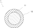
- FIG. 1 is a cross-sectional view schematically showing adhesive particles according to a first embodiment of the present invention.
- FIG. 2 is a cross-sectional view schematically showing a laminate using adhesive particles according to the first embodiment of the present invention.
- FIG. 3 is a cross-sectional view schematically showing a PDLC-type light control laminate using adhesive particles according to the first embodiment of the present invention.
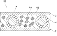
- FIG. 4 is a cross-sectional view schematically showing an SPD-type light control laminate using adhesive particles according to the first embodiment of the present invention.
- (meth)acrylate means one or both of “acrylate” and “methacrylate”
- (meth)acryl means one or both of "acrylic” and “methacrylic”. means both.
- An adhesive particle according to the present invention comprises a substrate particle and a coating portion arranged on the surface of the substrate particle.
- the covering portion contains a thermosetting resin.
- the adhesive particles according to the present invention have a 10% K value at 25° C. of 100 N/mm 2 or more and 3000 N/mm 2 or less.
- the adhesive particles according to the present invention have the above configuration, the adhesiveness of the adhesive particles can be sufficiently enhanced.
- the adhesive particles according to the present invention have the above configuration, when the adhesive particles are used as a material for the spacer particles, the separation of the spacer particles from the base material can be suppressed. and the gap between the substrates can be controlled with high precision.
- the adhesive particles according to the present invention have the above configuration, it is possible to prevent the substrate from being scratched.
- peeling of the base material can be suppressed when the particles are used in the light control laminate.
- the adhesive particles according to the present invention are provided with the above configuration, for example, even if the laminate has a curved surface portion, the adhesive particles do not move on the curved surface portion, and the base material The uniformity of the gap between them can be ensured.
- the adhesive particles according to the present invention can suppress the peeling of the adhesive particles from the substrate even if the laminate has a curved surface portion, so that the uniformity of the gap between the substrates can be ensured. can do. As a result, it is possible to suppress the occurrence of problems such as color unevenness in the liquid crystal display device caused by non-uniformity of the gap.
- a spherical shape is not limited to a true spherical shape, but includes a substantially spherical shape, and includes, for example, a shape having an aspect ratio (major axis/minor axis) of 1.5 or less.
- the 10% K value at 25° C. of the adhesive particles is 100 N/mm 2 or more and 3000 N/mm 2 or less.
- the 10% K value at 25° C. of the adhesive particles is preferably 200 N/mm 2 or more, more preferably 300 N/mm 2 or more, still more preferably 1000 N/mm 2 or more, and preferably 2800 N/mm 2 or less. , more preferably 2500 N/mm 2 or less, still more preferably 2000 N/mm 2 or less.
- the 10% K value at 25°C of the adhesive particles is equal to or higher than the lower limit and equal to or lower than the upper limit, the effects of the present invention can be exhibited more effectively. Also, the substrate can be prevented from being damaged. Further, when the 10% K value at 25° C. of the adhesive particles is equal to or higher than the lower limit and equal to or lower than the upper limit, peeling of the substrate can be further suppressed when used in the light control laminate. can.
- the 10% K value at 25°C of the adhesive particles can be measured as follows. Using a microcompression tester, the adhesive particles are compressed at 25° C. with a smooth indenter end face of a cylinder (50 ⁇ m in diameter, made of diamond) under conditions of applying a maximum test load of 20 mN for 60 seconds. The load value (N) and compression displacement (mm) at this time are measured. From the measured values obtained, the 10% K value at 25° C. can be obtained by the following formula. As the microcompression tester, for example, "Fischer Scope H-100" manufactured by Fisher Co., Ltd. is used.
- the 10% K value at 25° C. after heating the adhesive particles at 120° C. for 1 hour is preferably 110 N/mm 2 or more, more preferably 150 N/mm 2 or more, and still more preferably 300 N/mm 2 or more. Yes, preferably 3500 N/mm 2 or less, more preferably 3000 N/mm 2 or less, and even more preferably 2800 N/mm 2 or less.
- the 10% K value at 25°C after heating the adhesive particles at 120°C for 1 hour is at least the above lower limit and below the above upper limit, the effect of the present invention can be exhibited more effectively. . Also, the substrate can be prevented from being damaged. Further, when the 10% K value at 25° C. after heating the adhesive particles at 120° C. for 1 hour is equal to or higher than the lower limit and equal to or lower than the upper limit, when used in a light control laminate, the base material delamination can be further suppressed.
- the 10% K value at 25°C after heating the adhesive particles at 120°C for 1 hour (10% K value at 25°C after heating) can be measured as follows.
- the adhesive particles are heated at 120° C. for 1 hour in a blower constant temperature thermostat (for example, “DKN302” manufactured by Yamato Scientific Co., Ltd.).
- a microcompression tester the adhesive particles after heating are compressed at 25° C. with a smooth indenter end face of a cylinder (50 ⁇ m in diameter, made of diamond) under conditions of applying a maximum test load of 20 mN for 60 seconds.
- the load value (N) and compression displacement (mm) at this time are measured. From the measured values obtained, the 10% K value at 25° C. after heating can be obtained by the following formula.
- the microcompression tester for example, "Fischer Scope H-100" manufactured by Fisher Co., Ltd. is used.
- a method for controlling the 10% K value at 25° C. after heating the adhesive particles at 120° C. for 1 hour to a suitable range a method of adjusting the 10% K value at 25° C. of the substrate particles. , a method of using a preferable material for the covering portion, and a method of adjusting the contents of the thermosetting resin used for the covering portion and a curing agent to be described later.
- the 10% K value at 25° C. of the substrate particles is less than 100 N/mm 2 , it is preferable to control the 10% K value by using a preferred material for the coating portion.
- the compression recovery rate of the adhesive particles at 25°C is preferably 5% or more, more preferably 10% or more, and preferably 50% or less, more preferably 40% or less.
- the compression recovery rate at 25° C. of the adhesive particles is equal to or higher than the lower limit and equal to or lower than the upper limit, the effects of the present invention can be exhibited more effectively. Further, when the compression recovery rate of the adhesive particles at 25°C is equal to or higher than the lower limit and equal to or lower than the upper limit, peeling of the base material can be further suppressed when used in the light control laminate. .
- the compression recovery rate of the adhesive particles at 25°C can be measured as follows.
- a single adhesive particle that has been dispersed is subjected to a smooth indenter end face of a cylinder (50 ⁇ m in diameter, made of diamond) at 25° C. toward the center of the adhesive particle at an origin load value of 1.5°C.
- a compression recovery rate is derived by applying a load under the conditions of 0 mN and a reverse load value of 10 mN and analyzing the recovery behavior after the load is removed. By measuring the load-compression displacement during this period, the compression recovery rate can be obtained from the following formula. Note that the load speed is 0.33 mN/sec.
- the microcompression tester for example, "Fischer Scope H-100" manufactured by Fisher Co., Ltd. is used.
- Compression recovery rate (%) [L2/L1] x 100
- L1 Compressive displacement from the origin load value to the reverse load value when the load is applied
- L2 Unloading displacement from the reverse load value to the origin load value when releasing the load
- the particle size of the adhesive particles is preferably 1 ⁇ m or more, more preferably 3 ⁇ m or more, still more preferably 10 ⁇ m or more, preferably 150 ⁇ m or less, more preferably 100 ⁇ m or less, and It is preferably 50 ⁇ m or less.
- the particle diameter of the adhesive particles means the diameter when the adhesive particles are spherical, and when the adhesive particles have a shape other than a spherical shape, it is assumed to be a true sphere corresponding to the volume. means the diameter when The particle size of the adhesive particles is preferably an average particle size, more preferably a number average particle size.
- the average particle size of the adhesive particles can be measured by any particle size distribution analyzer. For example, it can be measured using a particle size distribution measuring apparatus using the principle of laser light scattering, electrical resistance value change, image analysis after imaging, or the like.
- a particle size distribution measuring device (“Multisizer 4" manufactured by Beckman Coulter) is used to measure the particle size of about 100,000 adhesive particles, and the average value is A method of calculating is exemplified.
- the CV value of the particle diameter of the adhesive particles is preferably 10% or less, more preferably 7% or less.
- the smaller the CV value of the particle diameter of the adhesive particles the better.
- the CV value of the particle diameter of the adhesive particles is equal to or less than the above upper limit. is performed, the adhesive particles can follow the laminate, and movement of the adhesive particles can be suppressed.
- the lower limit of the CV value of the particle diameter of the adhesive particles is not particularly limited.
- the CV value of the particle diameter of the adhesive particles may be 0% or more, or 7% or more.
- the CV value (variation coefficient) of the particle size of the adhesive particles can be measured as follows.
- CV value (%) ( ⁇ /Dn) ⁇ 100 ⁇ : standard deviation of the particle size of the adhesive particles Dn: average value of the particle size of the adhesive particles
- the aspect ratio of the adhesive particles is preferably 1.5 or less, more preferably 1.3 or less.
- the above aspect ratio indicates major axis/minor axis.
- the aspect ratio is obtained by observing 10 arbitrary adhesive particles with an electron microscope or an optical microscope, defining the maximum diameter and the minimum diameter as the major diameter and the minor diameter, respectively, and averaging the major diameter / minor diameter of each spherical adhesive particle. It is preferable to obtain by calculating the value.
- the lower limit of the aspect ratio of the adhesive particles is not particularly limited.
- the aspect ratio of the adhesive particles may be 1.0 or more, or 1.1 or more.
- the tensile yield stress of the adhesive particles is preferably 0.07 MPa or more, more preferably 0.10 MPa or more, and still more preferably 0.12 MPa or more. is preferred.
- the upper limit of the tensile yield stress of the adhesive particles is not particularly limited. In the following adhesion test A, the tensile yield stress of the adhesive particles may be 0.12 MPa or less, or 0.07 MPa or less.
- Adhesion test A Glass substrates are prepared as the first base material and the second base material. 14000 particles/mm 2 of adhesive particles are scattered on the surface of the first substrate. A second substrate is then placed over the adhesive particles. The adhesive particles are adhered to the first and second substrates by heating at 120° C. for 1 hour at a pressure of 5 kgf/cm 2 in accordance with the method of JIS K6850 to prepare a test body (test sample). .
- a Tensilon universal material testing machine for example, "RTI-1310" manufactured by A&D Co., Ltd.
- the adhesive strength of the specimen obtained at a tensile speed of 20 mm / min and a load cell rating of 1000 N is measured at 23 ° C. . This measured value is taken as the tensile yield stress of the adhesive particles.
- the 90° peel strength of the adhesive particles is preferably 0.1 N/30 mm or more, more preferably 0.5 N/30 mm or more, and still more preferably is preferably 1.0 N/30 mm or more.
- the upper limit of the 90° peel strength of the adhesive particles is not particularly limited.
- the 90° peel strength of the adhesive particles may be 10.0 N/30 mm or less, or 0.1 N/30 mm or less.
- Adhesion test B As the first base material and the second base material, according to a known method, films with alignment films are prepared by casting a polyimide solution on a PET film, drying, and rubbing. 14000 particles/mm 2 of adhesive particles are scattered on the surface of the first substrate. Then, according to the method of JIS K6850, the pressure is 5 kgf/cm 2 and the adhesive particles are heated at 120° C. for 1 hour to adhere the adhesive particles onto the first and second substrates, thereby forming a test body (test sample). make. Based on JIS K6854:1999, the measurement is performed using a tensile tester (for example, "Autograph AGS" manufactured by Shimadzu Corporation) at a tensile speed of 50 mm/sec. This measured value is taken as the 90° peel strength of the adhesive particles.
- a tensile tester for example, "Autograph AGS” manufactured by Shimadzu Corporation
- the adhesive particles according to the present invention are suitably used as materials for spacer particles.
- the adhesive particles according to the present invention are particularly suitable for use as a material for spacer particles in a light control laminate.
- the adhesive particles may be used as a material for spacer particles for a light control glass, or may be used as a material for spacer particles for a light control film.
- the adhesive particles are preferably used as a material for spacer particles for light control glass or a material for spacer particles for light control film.
- FIG. 1 is a cross-sectional view schematically showing adhesive particles according to the first embodiment of the present invention.
- the adhesive particles 1 include base particles 11 and coating portions 12 arranged on the surfaces of the base particles 11 .
- the covering portion 12 covers the surfaces of the substrate particles 11 .
- the adhesive particles 1 are coated particles in which the surfaces of the substrate particles 11 are coated with the coating portion 12 .
- the covering portion may completely cover the surface of the base particle, or may not completely cover the surface of the base particle.
- the substrate particles may have portions not covered with the covering portion.
- the covering portion 12 contains a thermosetting resin.
- the adhesive particles 1 have a 10% K value at 25° C. of 100 N/mm 2 or more and 3000 N/mm 2 or less.
- the material of the substrate particles is not particularly limited.
- the substrate particles may contain an organic material or may contain an inorganic material.
- organic material examples include polyolefin resins such as polyethylene, polypropylene, polystyrene, polyvinyl chloride, polyvinylidene chloride, polyisobutylene, and polybutadiene; acrylic resins such as polymethyl methacrylate and polymethyl acrylate; polycarbonates, polyamides, phenol formaldehyde resins, and melamine.
- polyolefin resins such as polyethylene, polypropylene, polystyrene, polyvinyl chloride, polyvinylidene chloride, polyisobutylene, and polybutadiene
- acrylic resins such as polymethyl methacrylate and polymethyl acrylate
- polycarbonates polyamides, phenol formaldehyde resins, and melamine.
- Formaldehyde resin benzoguanamine formaldehyde resin, urea formaldehyde resin, phenol resin, melamine resin, benzoguanamine resin, urea resin, epoxy resin, unsaturated polyester resin, saturated polyester resin, polyethylene terephthalate, polysulfone, polyphenylene oxide, polyacetal, polyimide, polyamideimide, Examples include polyetheretherketone, polyethersulfone, and divinylbenzene polymer.
- the divinylbenzene polymer may be a divinylbenzene copolymer.
- the divinylbenzene copolymer and the like examples include a divinylbenzene-styrene copolymer and a divinylbenzene-(meth)acrylate copolymer. Since the hardness of the adhesive particles and the substrate particles can be easily controlled within a suitable range, the substrate particles are formed by polymerizing one or more polymerizable monomers having an ethylenically unsaturated group. It preferably contains a polymer.
- the polymerizable monomer having an ethylenically unsaturated group includes a non-crosslinking monomer and a crosslinkable monomer. and monomers of the same type.
- non-crosslinkable monomers examples include vinyl compounds such as styrene monomers such as styrene, ⁇ -methylstyrene, and chlorostyrene; vinyl ether compounds such as methyl vinyl ether, ethyl vinyl ether, and propyl vinyl ether; vinyl acetate, vinyl butyrate, Acid vinyl ester compounds such as vinyl laurate and vinyl stearate; halogen-containing monomers such as vinyl chloride and vinyl fluoride; ) Alkyl ( meth) acrylate compounds; oxygen atom-containing (meth) acrylate compounds such as 2-hydroxyethyl (meth) acrylate, glycerol (meth) acrylate, polyoxyethylene (meth) acrylate, glycidyl (meth) acrylate; (meth) acrylonitrile and the like Nitrile-containing monomers; halogen-containing (meth)acrylate compounds such as trifluoromethyl (meth)acrylate and pentafluor
- crosslinkable monomers examples include vinyl monomers such as divinylbenzene, 1,4-divinyloxybutane and divinylsulfone as vinyl compounds; and tetramethylolmethane tetra(meth)acrylate as (meth)acrylic compounds.
- polytetramethylene glycol diacrylate tetramethylolmethane tri(meth)acrylate, tetramethylolmethane di(meth)acrylate, trimethylolpropane tri(meth)acrylate, dipentaerythritol hexa(meth)acrylate, dipentaerythritol penta(meth)acrylate ) acrylate, glycerol tri(meth)acrylate, glycerol di(meth)acrylate, polyethylene glycol di(meth)acrylate, polypropylene glycol di(meth)acrylate, polytetramethylene glycol di(meth)acrylate, 1,4-butanediol di Polyfunctional (meth)acrylate compounds such as (meth)acrylates; triallyl (iso)cyanurate, triallyl trimellitate, diallyl phthalate, diallyl acrylamide, diallyl ether as allyl compounds; tetrameth
- the substrate particles can be obtained by polymerizing the polymerizable monomer having the ethylenically unsaturated group.
- the polymerization method is not particularly limited, and includes known methods such as radical polymerization, ionic polymerization, polycondensation (condensation polymerization, polycondensation), addition condensation, living polymerization, and living radical polymerization.
- Other polymerization methods include suspension polymerization in the presence of a radical polymerization initiator.
- Examples of the inorganic material include silicate glass, borosilicate glass, lead glass, soda lime glass, alumina and alumina silicate glass.
- the substrate particles may be formed only of the organic material, may be formed only of the inorganic material, or may be formed of both the organic material and the inorganic material. From the viewpoint of easily controlling the compression properties of the substrate particles and the adhesive particles within a suitable range, the substrate particles may be made of only an organic material, or may be made of both an organic material and an inorganic material. It is preferable that
- the base particles may contain other components as necessary.
- the other components include coloring agents, polymerization inhibitors, polymerization initiators, pigment dispersants, polymer dispersants, surfactants, and the like. Only one of the other components may be used, or two or more thereof may be used in combination.
- the 10% K value at 25° C. of the substrate particles is preferably 100 N/mm 2 or more, more preferably 300 N/mm 2 or more, still more preferably 1000 N/mm 2 or more, and preferably 3000 N/mm 2 or less. , more preferably 2500 N/mm 2 or less, still more preferably 2000 N/mm 2 or less.
- the 10% K value at 25° C. of the substrate particles is equal to or higher than the lower limit and equal to or lower than the upper limit, the effects of the present invention can be exhibited even more effectively. Also, the substrate can be prevented from being damaged. Further, when the 10% K value at 25° C. of the substrate particles is at least the above lower limit and below the above upper limit, when the obtained adhesive particles are used in a light control laminate, the substrate does not peel off. can be further suppressed.
- the 10% K value at 25°C of the base particles can be measured as follows. Using a microcompression tester, the substrate particles are compressed at 25° C. with a smooth indenter end face of a cylinder (diameter 50 ⁇ m, made of diamond) under conditions of applying a maximum test load of 20 mN for 60 seconds. The load value (N) and compression displacement (mm) at this time are measured. From the measured values obtained, the 10% K value at 25° C. can be obtained by the following formula. As the microcompression tester, for example, "Fischer Scope H-100" manufactured by Fisher Co., Ltd. is used.
- the compression recovery rate of the substrate particles at 25°C is preferably 5% or more, more preferably 10% or more, and preferably 50% or less, more preferably 40% or less.
- the compression recovery rate at 25° C. of the substrate particles is equal to or higher than the lower limit and equal to or lower than the upper limit, the effects of the present invention can be exhibited more effectively. Further, when the compression recovery rate of the substrate particles at 25° C. is equal to or more than the lower limit and equal to or less than the upper limit, peeling of the substrate can be further suppressed when used in the light control laminate. .
- the compression recovery rate of the substrate particles at 25°C can be measured as follows.
- one dispersed substrate particle is subjected to a smooth indenter end face of a cylinder (50 ⁇ m in diameter, made of diamond) at 25° C. toward the center of the substrate particle with an origin load value of 1.5°C.
- a load is applied under the conditions of 0 mN and a reverse load value of 10 mN, and the compression recovery rate is derived by analyzing the recovery behavior after the load is removed. By measuring the load-compression displacement during this period, the compression recovery rate can be obtained from the following formula. Note that the load speed is 0.33 mN/sec.
- the microcompression tester for example, "Fischer Scope H-100" manufactured by Fisher Co., Ltd. is used.
- Compression recovery rate (%) [L2/L1] x 100
- L1 Compressive displacement from the origin load value to the reverse load value when the load is applied
- L2 Unloading displacement from the reverse load value to the origin load value when releasing the load
- the particle size of the substrate particles is preferably 1.0 ⁇ m or more, more preferably 5.0 ⁇ m or more, still more preferably 10 ⁇ m or more, and more preferably 50 ⁇ m or less, more preferably It is 40 ⁇ m or less, more preferably 30 ⁇ m or less.
- the particle size of the substrate particles is preferably the average particle size, more preferably the number average particle size.
- the particle diameter of the substrate particles is preferably determined by measuring the particle diameters of approximately 100,000 substrate particles using a particle size distribution analyzer and calculating the average particle diameter. Examples of the particle size distribution analyzer include "Multisizer 4" manufactured by Beckman Coulter.
- the CV value (variation coefficient) of the particle size of the substrate particles is preferably 10% or less, more preferably 7% or less, and even more preferably 5% or less.
- the lower limit of the CV value of the particle diameter of the substrate particles is not particularly limited.
- the CV value of the particle diameter of the substrate particles may be 2% or more.
- the CV value of the particle diameter of the substrate particles is expressed by the following formula.
- CV value (%) ( ⁇ /Dn) ⁇ 100 ⁇ : standard deviation of particle size of substrate particles Dn: average value of particle size of substrate particles
- the coating part is arranged on the surface of the substrate particle.
- the surface area (coverage) covered by the coating portion on the surface of the substrate particles is preferably 80% or more, out of 100% of the total surface area of the substrate particles. Preferably it is 90% or more.
- the upper limit of the coverage rate is not particularly limited. The coverage may be 100% or less.
- the above coverage is set to an image magnification of 10,000 times using a field emission scanning electron microscope (FE-SEM), 20 adhesive particles are randomly selected, and the surface of each adhesive particle is Observe. The percentage of the surface area of the portion of the adhesive particles covered with the substrate particles relative to the projected area of the entire substrate particles is measured, and the arithmetic mean is taken as the coverage.
- FE-SEM field emission scanning electron microscope
- the thickness of the coating portion is preferably 0.5 ⁇ m or more, more preferably 0.7 ⁇ m or more, still more preferably 1.0 ⁇ m or more, and preferably 8.0 ⁇ m or less. It is preferably 5.0 ⁇ m or less.
- the thickness of the coating portion means the thickness of the coating portion only in the portion where the coating portion is arranged on the surface of the substrate particle. A portion of the surface of the base material particle where there is no coating portion is not taken into consideration when calculating the thickness of the coating portion.
- the covering portion may be a single layer or two or more layers (multilayer).
- the thickness of the covering portion means the thickness of the entire covering portion.
- the materials forming each layer of the covering portion may be different.
- the thickness of the coating portion can be calculated from the difference between the particle size of the substrate particles and the particle size of the adhesive particles.
- the thickness of the coating portion can also be determined by observing the cross section of the adhesive particles using, for example, a transmission electron microscope (TEM).
- TEM transmission electron microscope
- the ratio of the thickness of the coating portion to the particle size of the substrate particles is preferably 0.001 or more, more preferably It is 0.01 or more, preferably 1.0 or less, more preferably 0.5 or less, and still more preferably 0.4 or less.
- the covering portion contains a thermosetting resin.
- thermosetting resins examples include epoxy resins, crosslinkable acrylic resins, phenol resins, melamine resins, urethane resins, and crosslinkable polyamide resins.
- the thermosetting resin in the coating preferably contains an epoxy resin, a crosslinkable acrylic resin, or a crosslinkable polyamide resin, and more preferably contains an epoxy resin.
- the epoxy resin is preferably a polyfunctional epoxy resin.
- the polyfunctional epoxy resin may be a bifunctional epoxy resin, a bifunctional or higher functional epoxy resin, a trifunctional epoxy resin, or a trifunctional or higher functional epoxy resin. , a tetrafunctional epoxy resin, or a tetrafunctional or higher epoxy resin.
- Bifunctional epoxy resins include bisphenol A type epoxy resins and bisphenol F type epoxy resins.
- the trifunctional epoxy resins include triazine-type epoxy resins and glycidylamine-type epoxy resins.
- Examples of the tetrafunctional epoxy resins include tetrakisphenolethane type epoxy resins and glycidylamine type epoxy resins. Only one type of the epoxy resin may be used, or two or more types may be used in combination.
- the above thermosetting resin is preferably used in combination with a curing agent.
- the curing agent cures the thermosetting resin.
- the curing agent is not particularly limited. Examples of the curing agent include imidazole curing agents, amine curing agents, phenol curing agents, thiol curing agents, and acid anhydride curing agents. Only one kind of the curing agent may be used, or two or more kinds thereof may be used in combination. From the viewpoint of easily controlling the compression properties of the adhesive particles within a suitable range, the curing agent is preferably an amine curing agent.
- the imidazole curing agent is not particularly limited.
- Examples of the imidazole curing agent include 2-methylimidazole, 2-ethyl-4-methylimidazole, 1-cyanoethyl-2-phenylimidazole, 1-cyanoethyl-2-phenylimidazolium trimellitate, 2,4-diamino-6.
- the thiol curing agent is not particularly limited.
- the thiol curing agent may be a polythiol curing agent.
- Examples of the thiol curing agent include trimethylolpropane tris-3-mercaptopropionate, pentaerythritol tetrakis-3-mercaptopropionate, and dipentaerythritol hexa-3-mercaptopropionate.
- the above amine curing agent is not particularly limited.
- examples of the amine curing agent include ethylenediamine, hexamethylenediamine, octamethylenediamine, decamethylenediamine, norbornanediamine, 3,9-bis(3-aminopropyl)-2,4,8,10-tetraspiro[5.5].
- undecane bis(4-aminocyclohexyl)methane, phenylenediamine, 2,2-bis[4-(4-aminophenoxy)phenyl]propane, metaphenylenediamine, diaminodiphenylmethane, diaminophenyl ether, metaxylenediamine, diaminonaphthalene, bisaminomethylcyclohexane, diaminodiphenylsulfone, and the like.
- the amine curing agent is ethylenediamine, hexamethylenediamine, octamethylenediamine, metaphenylenediamine, norbornanediamine, diaminodiphenylmethane, diaminodiphenylsulfone, phenylenediamine, or 2,2-bis[4-(4-aminophenoxy)phenyl].
- Propane is preferred.
- the amine curing agent is the preferred compound described above, the compression properties of the adhesive particles can be easily controlled within a suitable range.
- the amine curing agent may be ethylenediamine, norbornanediamine, phenylenediamine, or 2,2-bis[4-(4-aminophenoxy)phenyl ] Propane is more preferred, and norbornanediamine is even more preferred.
- the acid anhydride curing agent is not particularly limited.
- As the acid anhydride curing agent a wide range of acid anhydrides commonly used as curing agents for thermosetting resins such as epoxy resins can be used.
- Examples of the acid anhydride curing agent include phthalic anhydride, tetrahydrophthalic anhydride, trialkyltetrahydrophthalic anhydride, hexahydrophthalic anhydride, methylhexahydrophthalic anhydride, methyltetrahydrophthalic anhydride, and methylbutenyltetrahydrophthalic anhydride.
- anhydrides of phthalic acid derivatives maleic anhydride, nadic anhydride, methyl nadic anhydride, glutaric anhydride, succinic anhydride, glycerin bis trimellitic anhydride monoacetate, and ethylene glycol bis trimellitic anhydride.
- acid anhydride curing agent trifunctional acid anhydride curing agent such as trimellitic anhydride, and pyromellitic anhydride, benzophenone tetracarboxylic anhydride, methylcyclohexene tetracarboxylic anhydride, polyazelaic anhydride, etc. and a tetrafunctional or higher acid anhydride curing agent.
- the polymerization method is not particularly limited, and radical polymerization, ionic polymerization, polycondensation (condensation polymerization, condensation polymerization), addition condensation, living polymerization, living radical polymerization, etc. Polymerization can be carried out by known methods.
- the above adhesive particles can be easily obtained by performing dispersion polymerization or the like using a material containing a polyfunctional epoxy resin and a curing agent in a solution.
- a method of suspension polymerization using a solution in which a polyfunctional epoxy resin and a curing agent are dissolved as an oil layer and a method of polymerizing by swelling a solution in which a polyfunctional epoxy resin and a curing agent are dissolved using non-crosslinked seed particles. It can be obtained by a method such as a seed polymerization method.
- the content of the thermosetting resin in 100% by weight of the covering portion is preferably 30% by weight or more, more preferably 50% by weight or more, still more preferably 60% by weight or more, and particularly preferably 80% by weight or more. , preferably 100% by weight or less, more preferably 95% by weight or less, and even more preferably 90% by weight or less.
- the adhesiveness can be further enhanced.
- the content of the thermosetting resin in 100% by weight of the adhesive particles is preferably 10% by weight or more, more preferably 20% by weight or more, still more preferably 30% by weight or more, and particularly preferably 40% by weight or more. Yes, preferably 75% by weight or less, more preferably 70% by weight or less, and even more preferably 60% by weight or less.
- the adhesiveness can be further enhanced.
- the covering portion preferably contains a compound having a structure represented by the following formula (1).
- R1 and R2 each represent an organic group having an amino group, an organic group having an epoxy group, an organic group having an amide group, an organic group having an isocyanate group, or an organic group having a hydroxy group.
- R3 represents an alkyl group having 1 to 2 carbon atoms, an alkoxy group having 1 to 2 carbon atoms, or a vinyl group.
- p is 1 or 1.5.
- R4 represents a hydrogen atom, an alkyl group having 1 or 2 carbon atoms, an alkoxy group having 1 or 2 carbon atoms, or a vinyl group.
- p is 1.5
- q is 0 (R4 is absent).
- n represents an integer from 1 to 100;
- the above formula (1) is represented by the following formula (1A) when p is 1.
- R1 and R2 each represent an organic group having an amino group, an organic group having an epoxy group, an organic group having an amide group, an organic group having an isocyanate group, or an organic group having a hydroxyl group.
- R3 represents an alkyl group having 1 to 2 carbon atoms, an alkoxy group having 1 to 2 carbon atoms, or a vinyl group.
- R4 represents a hydrogen atom, an alkyl group having 1 to 2 carbon atoms, an alkoxy group having 1 to 2 carbon atoms, or a vinyl group.
- n represents an integer from 1 to 100;
- the above formula (1) is represented by the following formula (1B) when p is 1.5.
- R1 and R2 each represent an organic group having an amino group, an organic group having an epoxy group, an organic group having an amide group, an organic group having an isocyanate group, or an organic group having a hydroxy group.
- R3 represents an alkyl group having 1 to 2 carbon atoms, an alkoxy group having 1 to 2 carbon atoms, or a vinyl group.
- n represents an integer from 1 to 100;
- a compound having a structure represented by the above formula (1B) is generally called a polysilsesquioxane.
- q in the above formula (1) is 0 and R4 does not exist.
- R1 and R2 are each an organic group having an amino group, an organic group having an epoxy group, an organic group having an amide group, an organic group having an isocyanate group, or represents an organic group having a hydroxy group.
- R1 and R2 may be the same or different.
- R1 and R2 are each preferably an organic group having an amino group or an organic group having an epoxy group. .
- R3 represents an alkyl group having 1 to 2 carbon atoms, an alkoxy group having 1 to 2 carbon atoms, or a vinyl group. From the viewpoint of further improving the adhesiveness, in the above formulas (1), (1A) and (1B), R3 is preferably a methyl group, an ethyl group or a vinyl group, more preferably a methyl group. .
- R4 represents a hydrogen atom, an alkyl group having 1 to 2 carbon atoms, an alkoxy group having 1 to 2 carbon atoms, or a vinyl group. From the viewpoint of further enhancing adhesiveness, in the above formulas (1) and (1A), R4 is preferably a methyl group, an ethyl group or a vinyl group, more preferably a methyl group.
- n represents an integer of 1-100. From the viewpoint of further increasing the adhesiveness, in the above formulas (1), (1A) and (1B), n is preferably an integer of 2 or more, preferably an integer of 50 or less, more preferably an integer of 10 or less is.
- R3 and R4 may be the same or different.
- a plurality of R3 may be the same or different.
- a plurality of R4 may be the same or different.
- the compound having the structure represented by the above formula (1) may include the compound having the structure represented by the above formula (1A), and the compound having the structure represented by the above formula (1B). It may contain a compound having a structure represented by the above formula (1A) and a compound having a structure represented by the above formula (1B).
- the compound having the structure represented by formula (1) may include the compound having the structure represented by formula (1A) and the compound having the structure represented by formula (1B).
- the compound having the structure represented by the formula (1) may be a compound having the structure represented by the formula (1A) and the structure represented by the formula (1B).
- the structure represented by the above formula (1) may be the structure represented by the above formula (1A) or the structure represented by the above formula (1B).
- the compound having the structure represented by formula (1) above preferably contains the compound having the structure represented by formula (1A) above.
- the structure represented by the above formula (1) is preferably the structure represented by the above formula (1A).
- the content of the compound having the structure represented by the formula (1) in 100% by weight of the covering portion is preferably 1% by weight or more, more preferably 5% by weight or more, and still more preferably 10% by weight or more. , preferably 50% by weight or less, more preferably 40% by weight or less, and even more preferably 30% by weight or less.
- the adhesiveness can be further enhanced.
- the compound having the structure represented by the formula (1) includes both the compound having the structure represented by the formula (1A) and the compound having the structure represented by the formula (1B). be.
- the above content represents the sum of the content of the compound having the structure represented by formula (1A) and the content of the compound having the structure represented by formula (1B).
- the covering part may contain other components as necessary.
- the other components include coloring agents, polymerization initiators, polymerization inhibitors, adhesion imparting agents, anti-coloring agents, surfactants, polymer dispersants, and the like. Only one of the other components may be used, or two or more thereof may be used in combination.
- a laminate according to the present invention (hereinafter sometimes referred to as a laminate (A)) includes a first base material, a second base material, and the first base material and the second base material. and spacer particles disposed between.
- the spacer particles adhere to the first base material and the second base material.
- the material of the spacer particles contains the adhesive particles.
- the spacer particles can be formed in the laminate (A) by thermosetting the thermosetting resin or by reacting the compound having the structure represented by the formula (1). can. Further, the spacer particles can be formed between the first base material and the second base material by heat-curing the thermosetting resin or reacting the compound having the structure represented by the formula (1). It can be adhered to materials.
- a laminate (B) includes a first base material, a second base material, and the first base material and the second base material. spacer particles disposed between the substrate of the In the laminate (B), the spacer particles adhere to the first base material and the second base material.
- the material of the spacer particles contains the adhesive particles, and the spacer particles contain a compound having a structural unit represented by the following formula (11).
- the spacer particles can be formed in the laminate (B) by thermosetting the thermosetting resin or reacting the compound having the structure represented by the formula (1). can.
- the spacer particles can be formed between the first base material and the second base material by heat-curing the thermosetting resin or reacting the compound having the structure represented by the formula (1). It can be adhered to materials.
- R3 represents an alkyl group having 1 to 2 carbon atoms, an alkoxy group having 1 to 2 carbon atoms, or a vinyl group.
- p is 1 or 1.5.
- R4 represents a hydrogen atom, an alkyl group having 1 or 2 carbon atoms, an alkoxy group having 1 or 2 carbon atoms, or a vinyl group.
- p is 1.5, q is 0 (R4 is absent).
- n represents an integer from 1 to 100;
- the adhesiveness can be sufficiently improved, the separation of the spacer particles from the substrate is suppressed, and , the gap between the substrates can be controlled with high precision.
- the layered product (A) and the layered product (B) according to the present invention are provided with the above configuration, it is possible to prevent the substrate from being scratched.
- the layered product (A) and the layered product (B) according to the present invention have the above-described configuration, so that peeling of the base material can be suppressed when used in the light control layered product. .
- the layered product (A) and the layered product (B) according to the present invention are provided with the above-described configuration, for example, even if the layered product has a curved surface portion, the spacer particles are formed in the curved surface portion. The uniformity of the gap between the substrates can be ensured without being crushed. Moreover, even if the laminate has a curved surface portion, separation of the spacer particles from the base material can be suppressed, so that the uniformity of the gap between the base materials can be ensured. As a result, it is possible to suppress the occurrence of problems such as color unevenness in the liquid crystal display device caused by non-uniformity of the gap.
- R3 represents an alkyl group having 1 to 2 carbon atoms, an alkoxy group having 1 to 2 carbon atoms, or a vinyl group.
- R4 represents a hydrogen atom, an alkyl group having 1 to 2 carbon atoms, an alkoxy group having 1 to 2 carbon atoms, or a vinyl group.
- n represents an integer from 1 to 100;
- R3 represents an alkyl group having 1 to 2 carbon atoms, an alkoxy group having 1 to 2 carbon atoms, or a vinyl group.
- n represents an integer from 1 to 100;
- a compound having a structural unit represented by the above formula (11B) is generally called a polysilsesquioxane.
- q in the above formula (11) is 0 and R4 does not exist.
- R3 represents an alkyl group having 1 to 2 carbon atoms, an alkoxy group having 1 to 2 carbon atoms, or a vinyl group. From the viewpoint of further improving adhesiveness, in the above formulas (11), (11A) and (11B), R3 is preferably a methyl group, an ethyl group or a vinyl group, more preferably a methyl group. .
- R4 represents a hydrogen atom, an alkyl group having 1 to 2 carbon atoms, an alkoxy group having 1 to 2 carbon atoms, or a vinyl group. From the viewpoint of further enhancing adhesiveness, R4 in the above formulas (11) and (11A) is preferably a methyl group, an ethyl group or a vinyl group, more preferably a methyl group.
- n represents an integer of 1-100. From the viewpoint of further increasing the adhesiveness, in the above formulas (11), (11A) and (11B), n is preferably an integer of 2 or more, preferably an integer of 50 or less, more preferably an integer of 10 or less is.
- R3 and R4 may be the same or different.
- a plurality of R3 when n is 2 or more, a plurality of R3 may be the same or different.
- a plurality of R4 when n is 2 or more, a plurality of R4 may be the same or different.
- the compound having a structural unit represented by the formula (11) may contain a compound having a structural unit represented by the formula (11A), and has a structural unit represented by the formula (11B).
- a compound having a structural unit represented by the above formula (11A) and a compound having a structural unit represented by the above formula (11B) may be included.
- a compound having a structural unit represented by the formula (11) may include a compound having a structural unit represented by the formula (11A) and a compound having a structural unit represented by the formula (11B). . In this case, even if the compound having the structural unit represented by the formula (11) is a compound having the structural unit represented by the formula (11A) and the structural unit represented by the formula (11B) good.
- the structural unit represented by formula (11) above may be the structural unit represented by formula (11A) above, or the structural unit represented by formula (11B) above.
- the compound having the structural unit represented by formula (11) preferably contains a compound having the structural unit represented by formula (11A).
- the structural unit represented by formula (11) above is preferably the structural unit represented by formula (11A) above.
- the content of the compound having the structural unit represented by the above formula (11) is preferably 1% by weight or more, more preferably 5% by weight, based on 100% by weight of the spacer particles. Above, more preferably 10% by weight or more, preferably 50% by weight or less, more preferably 40% by weight or less, and even more preferably 30% by weight or less.
- the compound having the structural unit represented by the formula (11) includes both the compound having the structural unit represented by the formula (11A) and the compound having the structural unit represented by the formula (11B). may contain. In this case, the content represents the sum of the content of the compound having the structural unit represented by formula (11A) and the content of the compound having the structural unit represented by formula (11B).
- the spacer particles can be obtained by heating the adhesive particles.
- the spacer particles can be obtained, for example, by heating the adhesive particles at 80° C. to 150° C. for 0.5 hours to 3 hours. More specific conditions can be obtained, for example, by heating the adhesive particles at 120° C. for 1 hour.
- FIG. 2 is a cross-sectional view schematically showing a laminate using adhesive particles according to the first embodiment of the present invention.
- the spacer particles 1X are adhered to the first base material 2 and the second base material 3 .
- the material of the spacer particles 1X contains the adhesive particles.
- the spacer particles 1X contain a compound having a structural unit represented by formula (11) above.
- the spacer particles are formed in the layered body 51 by thermally curing the thermosetting resin or by reacting the compound having the structure represented by the formula (1). Further, the spacer particles can be formed between the first base material and the second base material by heat-curing the thermosetting resin or reacting the compound having the structure represented by the formula (1). glued to the material.
- the laminate may or may not have a curved surface portion.
- the laminate preferably has a curved surface portion.
- the laminate may have a folded or curved shape.
- the laminate preferably has a folded or curved shape, and is preferably used in a folded or curved shape.
- the laminate may have a bent portion or a curved portion.
- the laminate, the first substrate and the second substrate are flexible so that they can have a folded or curved shape.
- the curvature of the curved surface portion of the laminate is preferably 300R or more and 1800R or less.
- the adhesive particles according to the present invention can be used to reduce the thickness of the entire laminate. Adhesion can be sufficiently enhanced over a long period of time. Furthermore, separation from the substrate can be suppressed, and the gap between the substrates can be controlled with high accuracy.
- the laminate is preferably used for vehicle window glass, partitions, or the like.
- Examples of the vehicle include vehicles, ships, aircraft, and the like.
- the laminate is preferably used for window glass of vehicles such as vehicles, ships, and aircraft, partitions, and the like.
- the laminate is preferably a windowpane or a partition, and more preferably a windowpane or a partition for a vehicle such as a vehicle, ship, or aircraft.
- the laminate may be a window glass for a vehicle such as a vehicle, a ship, an aircraft, or the like, or may be a partition.
- the vehicle is a transportation vehicle.
- the partition may be a member that is arranged between the seats of the vehicle and partitions the seats.
- the laminate may be a light modulating laminate.
- the laminate is suitably used as a light control laminate.
- the layered product is a light control layered product, it is preferable that the layered product further includes a light control layer arranged between the first base material and the second base material.
- the light modulating layer contains the spacer particles.
- the light control layered product may be a PDLC (Polymer Dispersed Liquid Crystal) type light control layered product or an SPD (Suspended Particle Device) type light control layered product.
- the light control layered product is preferably an SPD type or PDLC type light control layered product.
- the light control laminate may not be a liquid crystal display device.
- FIG. 3 is a cross-sectional view schematically showing a PDLC-type light control laminate using adhesive particles according to the first embodiment of the present invention.
- FIG. 4 is a cross-sectional view schematically showing an SPD-type light control laminate using adhesive particles according to the first embodiment of the present invention. 3 and 4, the size, thickness, shape and amount of addition of the light modulating layer and the adhesive particles are appropriately changed from the actual size and shape for convenience of illustration.
- the light modulating layer 4 is sandwiched between the first base material 2 and the second base material 3 .
- the light control layer 4 is arranged between the first base material 2 and the second base material 3 .
- a sealant may be arranged around the light control layer 4 .
- the light control layer 4 includes spacer particles 1X, liquid crystal capsules 4A, and binders 4B.
- the liquid crystal capsule 4A is a liquid crystal material.
- the liquid crystal capsules 4A are dispersed in the binder 4B.
- the liquid crystal capsule 4A is held in a capsule shape in the binder 4B.
- the liquid crystal material may be encapsulated and dispersed in the binder, or the liquid crystal material may be dispersed in the binder as a continuous phase.
- the spacer particles 1X are in contact with the first base material 2 and the second base material 3.
- the spacer particles 1X control the gap between the first base material 2 and the second base material 3.
- the spacer particles 1X contain a compound having a structural unit represented by formula (11) above.
- the material of the spacer particles 1X contains the adhesive particles described above.
- Electrodes are formed on the surface of the first base material 2 and on the surface of the second base material 3 (not shown). Examples of materials for the electrodes include indium tin oxide (ITO). The electrodes are preferably transparent electrodes.
- the orientation of the liquid crystal molecules in the liquid crystal capsule 4A is not uniform. It scatters in the binder and becomes opaque.
- the liquid crystal molecules in the liquid crystal capsule 4A are aligned in a direction parallel to the electric field.
- the binder 4B and the liquid crystal material have the same refractive index, light can be transmitted therethrough, resulting in a transparent state.
- the light modulating layer 5 is sandwiched between the first substrate 2 and the second substrate 3 .
- the light control layer 5 is arranged between the first base material 2 and the second base material 3 .
- the light control layer 5 includes spacer particles 1X, light control suspension liquid droplets 5A, and a resin matrix 5B. Droplets 5A of light conditioning suspension are dispersed in a resin matrix 5B. The droplets 5A of the light control suspension are held in a droplet state in the resin matrix 5B.
- the droplets 5A of the light adjusting suspension contain the dispersion medium 5Aa and the light adjusting particles 5Ab.
- the light adjusting particles 5Ab are dispersed in the dispersion medium 5Aa.
- the spacer particles 1X are in contact with the first base material 2 and the second base material 3.
- the spacer particles 1X control the gap between the first base material 2 and the second base material 3.
- the spacer particles 1X contain a compound having a structural unit represented by formula (11) above.
- the material of the spacer particles 1X contains the adhesive particles described above.
- Electrodes are formed on the surface of the first base material 2 and on the surface of the second base material 3 (not shown). Examples of materials for the electrodes include indium tin oxide (ITO). The electrodes are preferably transparent electrodes.
- the light adjustment particles 5Ab are arranged in a direction parallel to the electric field. Therefore, the incident light can pass between the arranged light adjusting particles 5Ab and can be transmitted through the light adjusting layer 5.
- the light control layer preferably has light control properties. Dimmability is a property that the visible light transmittance changes depending on whether or not an electric field is applied, and the amount of incident light can be adjusted.
- the light control layer includes the spacer particles.
- the light modulating layer preferably further includes a binder and a liquid crystal material dispersed in the binder.
- the liquid crystal material is not particularly limited, and may be any liquid crystal material as long as it has the property of changing its orientation when an electric field is applied.
- the liquid crystal material may be dispersed in the binder as a continuous phase, or may be dispersed in the binder in the form of liquid crystal drops or liquid crystal capsules.
- Examples of the liquid crystal material include nematic liquid crystal and cholesteric liquid crystal.
- nematic liquid crystal Materials for the nematic liquid crystal include cyanobiphenyl, phenyl ester, azoxybenzene, fluorine-containing biphenyl, carbonate, and Schiff base materials. Only one kind of the nematic liquid crystal material may be used, or two or more kinds thereof may be used in combination.
- Materials for the cholesteric liquid crystal include steroidal cholesterol derivatives, Schiff bases, azos, azoxys, benzoates, biphenyls, terphenyls, cyclohexylcarboxylates, phenylcyclohexanes, biphenylcyclohexanes, and pyrimidines.
- cholesteric liquid crystal material Only one kind of the cholesteric liquid crystal material may be used, or two or more kinds thereof may be used in combination.
- the binder holds the liquid crystal material and suppresses the flow of the liquid crystal material.
- the binder is not particularly limited as long as it does not dissolve in the liquid crystal material, has strength to withstand external force, and has high transparency to reflected light and incident light.
- the binder material include water-soluble polymer materials such as gelatin, polyvinyl alcohol, cellulose derivatives, polyacrylic acid-based polymers, ethyleneimine, polyethylene oxide, polyacrylamide, polystyrene sulfonate, polyamidine, isoprene-based sulfonic acid polymers, and materials capable of forming an aqueous emulsion such as fluorine resin, silicone resin, acrylic resin, urethane resin, and epoxy resin. Only one kind of the binder material may be used, or two or more kinds thereof may be used in combination.
- the binder is preferably crosslinked with a crosslinking agent.
- the cross-linking agent is not particularly limited as long as it forms cross-links between the binders and hardens the binder, makes it insoluble, or makes it insoluble.
- Examples of the cross-linking agent include acetaldehyde, glutaraldehyde, glyoxal, potassium alum hydrate of a polyvalent metal salt compound, adipic acid dihydrazide, melamine formalin oligomer, ethylene glycol diglycidyl ether, polyamide epichlorohydrin, and polycarbodiimide. mentioned. Only one kind of the crosslinking agent may be used, or two or more kinds thereof may be used in combination.
- the light control layer further comprises a resin matrix and a light control suspension dispersed in the resin matrix.
- the light control suspension contains a dispersion medium and light control particles dispersed in the dispersion medium.
- the light adjusting particles include carbon-based materials such as polyiodide and carbon black, metal materials such as copper, nickel, iron, cobalt, chromium, titanium, and aluminum, and inorganic compound materials such as silicon nitride, titanium nitride, and aluminum oxide. etc. Also, these materials may be particles coated with a polymer. Only one type of the light adjusting particles may be used, or two or more types may be used in combination.
- the dispersion medium disperses the light adjustment particles in a fluid state.
- the dispersion medium selectively adheres to the light control particles, coats the light control particles, and causes the light control particles to migrate to the phase-separated droplet phase upon phase separation from the resin matrix.
- It is preferably a material that is functional, non-electrically conductive, and incompatible with the resin matrix.
- the dispersion medium is preferably a liquid copolymer having a refractive index similar to that of the resin matrix when the light control laminate is formed.
- a (meth)acrylic ester oligomer having a fluoro group or a hydroxyl group is preferable, and a (meth)acrylic ester oligomer having a fluoro group and a hydroxyl group is more preferable.
- the fluoro or hydroxyl monomer units are oriented toward the light modulating particles and the remaining monomer units stabilize the droplets of the light modulating suspension in the resin matrix. Therefore, the light control particles are easily dispersed in the light control suspension, and the light control particles are easily guided into the phase-separated droplets during phase separation from the resin matrix.
- Examples of the (meth)acrylic acid ester oligomer having a fluoro group or a hydroxyl group include 2,2,2-trifluoroethyl methacrylate/butyl acrylate/2-hydroxyethyl acrylate copolymer, and 3,5,5 acrylic acid.
- the weight average molecular weight of the (meth)acrylate oligomer is preferably 1000 or more, more preferably 2000 or more, and preferably 20000 or less, more preferably 10000 or less.
- the light control layer can be produced using the resin material for forming the resin matrix and the light control suspension.
- the resin material is preferably a resin material that cures when irradiated with energy rays.
- resin materials that are cured by irradiation with energy rays include polymer compositions that contain photopolymerization initiators and polymer compounds that are cured by energy rays such as ultraviolet rays, visible rays, and electron beams.
- the polymer composition include a polymer composition containing a polymerizable monomer having an ethylenically unsaturated group and a photopolymerization initiator.
- the polymerizable monomer having an ethylenically unsaturated group include non-crosslinkable monomers and crosslinkable monomers.
- non-crosslinkable monomers examples include vinyl compounds such as styrene monomers such as styrene, ⁇ -methylstyrene, and chlorostyrene; vinyl ether compounds such as methyl vinyl ether, ethyl vinyl ether, and propyl vinyl ether; vinyl acetate, vinyl butyrate, Acid vinyl ester compounds such as vinyl laurate and vinyl stearate; halogen-containing monomers such as vinyl chloride and vinyl fluoride; ) Alkyl ( meth) acrylate compounds; oxygen atom-containing (meth) acrylate compounds such as 2-hydroxyethyl (meth) acrylate, glycerol (meth) acrylate, polyoxyethylene (meth) acrylate, glycidyl (meth) acrylate; (meth) acrylonitrile and the like Nitrile-containing monomers; halogen-containing (meth)acrylate compounds such as trifluoromethyl (meth)acrylate and pentafluor
- crosslinkable monomers examples include vinyl monomers such as divinylbenzene, 1,4-divinyloxybutane and divinylsulfone as vinyl compounds; and tetramethylolmethane tetra(meth)acrylate as (meth)acrylic compounds.
- polytetramethylene glycol diacrylate tetramethylolmethane tri(meth)acrylate, tetramethylolmethane di(meth)acrylate, trimethylolpropane tri(meth)acrylate, dipentaerythritol hexa(meth)acrylate, dipentaerythritol penta(meth)acrylate ) acrylate, glycerol tri(meth)acrylate, glycerol di(meth)acrylate, polyethylene glycol di(meth)acrylate, polypropylene glycol di(meth)acrylate, polytetramethylene glycol di(meth)acrylate, 1,3-butylene glycol di(meth)acrylate Polyfunctional (meth)acrylate compounds such as (meth)acrylate, 1,4-butanediol di(meth)acrylate, 1,6-hexanediol di(meth)acrylate, 1,9-nonaned
- photopolymerization initiator examples include 2,2-dimethoxy-1,2-diphenylethan-1-one, 1-(4-(2-hydroxyethoxy)phenyl)-2-hydroxy-2-methyl-1-propane -1-one, bis(2,4,6-trimethylbenzoyl)phenylphosphine oxide, 2-hydroxy-2-methyl-1-phenylpropan-1-one, and (1-hydroxycyclohexyl)phenylketone. be done.
- the resin material may contain organic solvent-soluble resin, thermoplastic resin, poly(meth)acrylic acid, and the like.
- the resin material may contain various additives such as an anti-coloring agent, an antioxidant, and an adhesion imparting agent, and may contain a solvent.
- the first substrate is preferably a transparent substrate.
- the second base material is preferably a transparent base material.
- the transparent substrate is, for example, a substrate having optical transparency (light transmissive substrate). For example, light is transmitted from one side of the transparent substrate to the other side through the transparent substrate. For example, when viewing a substance on the other side through the transparent substrate from one side of the transparent substrate, the substance can be visually recognized. Transparency also includes translucence, for example.
- the transparent substrate may be colorless and transparent, or may be colored and transparent.
- the materials of the first base material and the second base material are not particularly limited.
- the material of the first base material and the material of the second base material may be the same or different.
- materials for the first base material and the second base material include glass and resin films.
- the glass include soda-lime glass, lead glass, borosilicate glass for general construction, glasses of various compositions for other applications, and functional glasses such as heat-reflecting glass, heat-absorbing glass, and tempered glass.
- the resin film include polyester films such as polyethylene terephthalate, polyolefin films such as polypropylene, and resin films such as acrylic resin films.
- the first substrate and the second substrate are preferably resin substrates, more preferably resin films, because they are excellent in transparency, moldability, adhesiveness, processability, and the like. , more preferably a polyethylene terephthalate (PET) film.
- PET polyethylene terephthalate
- the first base material and the second base material may include a base body and a conductive film formed on the surface of the base body so that an electric field for dimming can be applied.
- the conductive film include indium tin oxide (ITO), SnO 2 and In 2 O 3 .
- the conductive film is preferably a transparent conductive film.
- the visible light transmittance of the first base material and the second base material is preferably 75% or more, more preferably 80% or more.
- the visible light transmittance of the first base material and the second base material can be measured in accordance with ISO13837:2008 by carrying out spectrometry or the like.
- Base particles A (acrylic-divinylbenzene copolymer particles, average particle size 15.0 ⁇ m, prepared according to Synthesis Example 1 below)
- Base particles B carbon black-dispersed acrylic-divinylbenzene copolymer particles, average particle size 18.0 ⁇ m, prepared according to Synthesis Example 2 below)
- Base particles C (acrylic-divinylbenzene copolymer particles, average particle size 15.0 ⁇ m, prepared according to Synthesis Example 3 below)
- Base particle D (“Micropearl SP-215" manufactured by Sekisui Chemical Co., Ltd., average particle size 15.0 ⁇ m)
- Substrate particles E (silicone particles, average particle size 16.0 ⁇ m, prepared according to Synthesis Example 4 below)
- Base particles F (acrylic-divinylbenzene copolymer particles, average particle size 20.0 ⁇ m, prepared according to Synthesis Example 5 below)
- Base particles G (“Micropearl SP-220” manufactured by Sekisui Chemical
- Synthesis example 1 Polystyrene particles having an average particle size of 5.0 ⁇ m were prepared as seed particles. 3.5 parts by weight of the above polystyrene particles, 500 parts by weight of ion-exchanged water, and 120 parts by weight of a 5% by weight aqueous solution of polyvinyl alcohol were mixed to prepare a mixed solution. After ultrasonically dispersing the mixed liquid, the mixed liquid was placed in a separable flask and uniformly stirred.
- Synthesis example 2 Polystyrene particles having an average particle size of 5.0 ⁇ m were prepared as seed particles. 3.5 parts by weight of the above polystyrene particles, 500 parts by weight of ion-exchanged water, and 120 parts by weight of a 5% by weight aqueous solution of polyvinyl alcohol were mixed to prepare a mixed solution. After ultrasonically dispersing the mixed liquid, the mixed liquid was placed in a separable flask and uniformly stirred.
- the emulsified liquid was added in two portions to the mixed liquid in the separable flask and stirred for 8 hours to allow the seed particles to absorb the monomer, thereby obtaining a suspension containing seed particles in which the monomer was swollen. . After that, 400 parts by weight of a 5% by weight aqueous solution of polyvinyl alcohol was added, and heating was started to react at 85° C. for 11 hours to obtain particles. The obtained particles were purified to obtain substrate particles B by a classification operation.
- the aqueous solution B was added. After that, emulsification was performed using a Shirasu Porous Glass (SPG) membrane (average pore size: about 20 ⁇ m). After that, the temperature was raised to 85° C. and polymerization was carried out for 9 hours. The whole amount of the polymerized particles was washed with water by centrifugation, classified, and freeze-dried to obtain substrate particles E.
- SPG Shirasu Porous Glass
- Polystyrene particles having an average particle size of 5.0 ⁇ m were prepared as seed particles. 3.5 parts by weight of the above polystyrene particles, 500 parts by weight of ion-exchanged water, and 120 parts by weight of a 5% by weight aqueous solution of polyvinyl alcohol were mixed to prepare a mixed solution. After ultrasonically dispersing the mixed liquid, the mixed liquid was placed in a separable flask and uniformly stirred.
- Thermosetting resin Epoxy resin (equal mixture of "EPICLON-EXA-850CRP” manufactured by DIC and "EPICLON-EXA-4850-150” manufactured by DIC) Polyamide resin ("Aronmighty FS-1750SV10" manufactured by Toagosei Co., Ltd.)
- Curing agent I amine curing agent, "Norbornanediamine” manufactured by Mitsui Chemicals Fine Co., Ltd.
- Curing agent II aromatic amine curing agent, "4,4'-diaminodiphenylmethane” manufactured by Tokyo Chemical Industry Co., Ltd.
- a compound having a structure represented by the above formula (1) Compound A ("X-22-163" manufactured by Shin-Etsu Silicone Co., Ltd.)
- Adhesive particles were produced in the same manner as in Example 1, except that the type of substrate particles and the structure of the coating portion were changed as shown in Tables 1-4.
- Example 10 3 parts by weight of base particles C, 15 parts by weight of polyamide resin, 4.8 parts by weight of cetyltrimethylammonium bromide as a dispersion stabilizer, and 100 parts by weight of ethanol were placed in a reaction vessel equipped with a thermometer, a stirrer and a cooling tube. was added and uniformly dissolved by stirring at 25° C. for 1 hour. Next, 1000 parts by weight of a 5% by weight aqueous solution of polyvinyl alcohol was added to the container to obtain a composite of the substrate particles and the polyamide resin. After freeze-drying the resulting composite, a classification operation was performed to recover the adhesive particles.
- a light control film was prepared in which a known SPD layer was arranged between two sheets of PET film on which transparent and conductive ITO was vapor-deposited, except that 5% by weight of the obtained adhesive particles were dispersed.
- the light control film was sandwiched between two sheets of transparent glass, a weight of 5 kg was placed, and the film was placed on a hot plate and heated at 120° C. for 1 hour to bond the upper and lower substrates.
- sandwiching the light control film between two sheets of transparent glass an SPD type light control laminate in which spacer particles are adhered to the first and second substrates was produced.
- a light control film was prepared by disposing a known PDLC layer between two sheets of PET film on which transparent and conductive ITO was vapor-deposited, except that 5% by weight of the obtained adhesive particles were dispersed.
- the light control film was sandwiched between two sheets of transparent glass, a weight of 5 kg was placed, and the film was placed on a hot plate and heated at 120° C. for 1 hour to bond the upper and lower substrates.
- a PDLC type light control laminate in which spacer particles are adhered to the first and second substrates was produced.
- Average Particle Size About 100,000 particles of the obtained adhesive particles were measured for particle size using a particle size distribution analyzer (“Multisizer 4” manufactured by Beckman Coulter, Inc.) to measure the average particle size.
- Adhesion tensile yield stress
- a test body test sample was prepared according to the above-described adhesion test A.
- Tensilon universal material testing machine RTI-1310 manufactured by A&D was used to measure the tensile yield stress of the specimen at 23°C (adhesion test A).
- Adhesion (tensile yield stress) was determined according to the following criteria.
- Tensile yield stress is 0.12 MPa or more
- Tensile yield stress is 0.10 MPa or more and less than 0.12 MPa
- Tensile yield stress is 0.07 MPa or more and less than 0.10 MPa
- Tensile yield stress is 0.07 MPa less than
- Adhesiveness (90° peel strength) Using the obtained adhesive particles, a test body (test sample) was prepared according to the above-described adhesion test B. In accordance with JIS K6854: 1999, using a tensile tester ("Autograph AGS" manufactured by Shimadzu Corporation), the 90 ° peel strength at 23 ° C. of the above test body was measured at a tensile speed of 50 mm / sec (adhesion sex test B). Adhesiveness (90° peel strength) was judged according to the following criteria.
- 90° peel strength is 1.0 N/30 mm or more ⁇ : 90° peel strength is 0.5 N/30 mm or more and less than 1.0 N/30 mm ⁇ : 90° peel strength is 0.1 N/30 mm or more, 0. Less than 5N/30mm x: 90° peel strength less than 0.1N/30mm
- the obtained light control laminate was curved using a cylindrical plate having a curvature of 0.1 to obtain a light control laminate having a curved surface portion.
- VHX-2000 manufactured by Keyence Corporation
- the number of remaining spacer particles was counted in five arbitrary 1 cm 2 regions on the surface of the second substrate. The standard deviation of the number of remaining spacer particles was determined, and the survivability of the spacer particles was judged according to the following criteria.
- Standard deviation is less than 2 ⁇ : Standard deviation is 2 or more and less than 4 ⁇ : Standard deviation is 4 or more and less than 6 ⁇ : Standard deviation is 6 or more
- the obtained light control laminate was curved using a cylindrical plate having a curvature of 0.1 to obtain a light control laminate having a curved surface portion.
- the thickness of the light modulating layer of the light modulating laminate was measured using a scanning electron microscope.
- the ratio of the minimum thickness of the light control layer to the maximum thickness of the light control layer was calculated, and the gap controllability was calculated as follows. Judged by the standard.
- composition and results of the adhesive particles are shown in Tables 1 to 4 below.
Abstract
Provided are adhesive particles capable of sufficiently enhancing adhesiveness, suppressing peeling from base materials, and highly accurately controlling a gap between the base materials. Adhesive particles (1) according to the present invention each comprise: a base material particle (11); and a cover (12) disposed on the surface of the base material particle. The cover includes a thermosetting resin, and a 10% K value of the adhesive particles at 25℃ is 100-3000 N/mm2.<sp />
Description
本発明は、接着性粒子、及び上記接着性粒子を用いた積層体に関する。
The present invention relates to adhesive particles and laminates using the adhesive particles.
液晶表示装置及び車載用ディスプレイ等のディスプレイ装置に、調光ガラスや調光フィルム等の調光材料が用いられることがある。調光材料は、電界の印加の有無により光透過率が変化する性質を有し、入射光量の調整が可能な材料である。近年、ディスプレイ装置の大画面化、曲面化に伴い、曲面部を有する調光材料のニーズが高まっている。該調光材料では、基材間のギャップを制御するために、スペーサとして粒子が用いられている。また、該調光材料では、2枚のガラス又はフィルム基材を貼り合わせるために、接着剤が用いられることがある。
Light control materials such as light control glass and light control film are sometimes used in display devices such as liquid crystal display devices and in-vehicle displays. The light modulating material is a material that has the property that the light transmittance changes depending on whether or not an electric field is applied, and the amount of incident light can be adjusted. In recent years, with the increase in screen size and curved surface of display devices, there is an increasing need for a light modulating material having a curved surface portion. The light modulating material uses particles as spacers to control the gap between the substrates. Moreover, in the light modulating material, an adhesive may be used to bond two sheets of glass or film substrates together.
また、液晶表示素子は、2枚のガラス又はフィルム基材間に液晶が配置されて構成されている。該液晶表示素子では、基材間のギャップを制御するために、スペーサとして粒子が用いられている。また、該液晶表示素子では、2枚のガラス又はフィルム基材を貼り合わせるために、接着剤が用いられることがある。
In addition, the liquid crystal display element is constructed by arranging liquid crystal between two glass or film substrates. In the liquid crystal display element, particles are used as spacers in order to control the gap between the substrates. Also, in the liquid crystal display element, an adhesive is sometimes used to bond two sheets of glass or film substrates together.
下記の特許文献1には、基材粒子と、上記基材粒子の表面上に配置された被覆部とを備える粒子が開示されている。該粒子では、上記被覆部の材料が特定の構造を有する化合物である。特許文献1には、該被覆部の材料として、熱可塑性樹脂が記載されている。
Patent Document 1 below discloses a particle comprising a substrate particle and a coating portion disposed on the surface of the substrate particle. In the particles, the material of the coating portion is a compound having a specific structure. Patent Literature 1 describes a thermoplastic resin as a material for the covering portion.
また、下記の特許文献2には、光硬化性化合物又は熱硬化性化合物により形成されている、硬化性樹脂粒子が開示されている。
In addition, Patent Document 2 below discloses curable resin particles formed from a photocurable compound or a thermosetting compound.
近年、ディスプレイ装置の大画面化、フレキシブル化に伴い、より高い接着性を有する接着剤のニーズが高まっている。また、接着性をより一層高めるために、接着性を有する粒子(接着性粒子)を用いることが考えられる。
In recent years, as display devices have become larger and more flexible, the need for adhesives with higher adhesiveness has increased. Moreover, in order to further improve the adhesiveness, it is conceivable to use particles having adhesiveness (adhesive particles).
特許文献1のように基材粒子の表面が熱可塑性樹脂で被覆され粒子では、粒子自体の接着性がさほどないことが想定される。
In the case of particles in which the surface of the substrate particles is coated with a thermoplastic resin as in Patent Document 1, it is assumed that the particles themselves do not have much adhesiveness.
また、従来の接着性粒子では、接着性を十分に高めることが困難なことがある。また、粒子本体と、該粒子本体を被覆する接着層とを備える接着性粒子では、接着層を十分に厚くすることができず、結果として粒子の接着性を十分に高めることが困難なことがある。また、加熱時に接着層が溶融して液だれが発生し、結果として接着性が低下することがある。
In addition, with conventional adhesive particles, it is sometimes difficult to sufficiently increase adhesiveness. In addition, in adhesive particles comprising a particle body and an adhesive layer covering the particle body, the adhesive layer cannot be made sufficiently thick, and as a result, it is difficult to sufficiently increase the adhesiveness of the particles. be. In addition, the adhesive layer melts during heating and drips may occur, resulting in a decrease in adhesiveness.
接着性の不十分な粒子を用いた積層体では、粒子が基材から剥がれて、基材間のギャップのばらつきが生じやすい。特に、積層体が曲面部を有する場合には、スペーサ粒子の基材からの剥離を抑制し、かつ、基材間のギャップの均一性を確保することは非常に困難である。
In a laminate using particles with insufficient adhesiveness, the particles tend to separate from the base material, causing variations in the gap between the base materials. In particular, when the laminate has a curved surface portion, it is very difficult to suppress separation of the spacer particles from the base material and to ensure uniformity of the gap between the base materials.
また、接着性粒子の接着後の硬度が高い場合には、基材を曲面化したときに、粒子と接触している基材に大きな圧力がかかることで、粒子が基材から剥がれて、基材間のギャップのばらつきが生じることがある。
Further, when the hardness of the adhesive particles after adhesion is high, when the substrate is curved, a large pressure is applied to the substrate in contact with the particles, causing the particles to peel off from the substrate. Variations in the gap between parts may occur.
本発明の目的は、接着性を十分に高めることができ、基材からの剥離を抑制し、かつ、基材間のギャップを高精度に制御することができる接着性粒子を提供することである。また、本発明の目的は、上記接着性粒子を用いた積層体を提供することである。
An object of the present invention is to provide adhesive particles capable of sufficiently enhancing adhesiveness, suppressing separation from substrates, and controlling the gap between substrates with high precision. . Another object of the present invention is to provide a laminate using the adhesive particles.
本発明の広い局面によれば、基材粒子と、前記基材粒子の表面に配置された被覆部とを備え、前記被覆部が、熱硬化性樹脂を含み、25℃での10%K値が、100N/mm2以上3000N/mm2以下である、接着性粒子が提供される。
According to a broad aspect of the present invention, it comprises a substrate particle and a coating disposed on the surface of the substrate particle, the coating comprising a thermosetting resin and having a 10% K value at 25°C. is 100 N/mm 2 or more and 3000 N/mm 2 or less.
本発明に係る接着性粒子のある特定の局面では、接着性粒子を120℃で1時間加熱した後の25℃での10%K値が、110N/mm2以上3500N/mm2以下である。
In a specific aspect of the adhesive particles according to the present invention, the 10% K value at 25° C. after heating the adhesive particles at 120° C. for 1 hour is 110 N/mm 2 or more and 3500 N/mm 2 or less.
本発明に係る接着性粒子のある特定の局面では、前記基材粒子の25℃での10%K値が、100N/mm2以上3000N/mm2以下である。
In a specific aspect of the adhesive particles according to the present invention, the base particles have a 10% K value at 25° C. of 100 N/mm 2 or more and 3000 N/mm 2 or less.
本発明に係る接着性粒子のある特定の局面では、25℃での圧縮回復率が、5%以上50%以下である。
In a specific aspect of the adhesive particles according to the present invention, the compression recovery rate at 25°C is 5% or more and 50% or less.
本発明に係る接着性粒子のある特定の局面では、前記被覆部の厚みが、0.5μm以上5.0μm以下である。
In a specific aspect of the adhesive particles according to the present invention, the coating portion has a thickness of 0.5 μm or more and 5.0 μm or less.
本発明に係る接着性粒子のある特定の局面では、前記被覆部が、下記式(1)で表される構造を有する化合物を含む。
In a specific aspect of the adhesive particles according to the present invention, the coating contains a compound having a structure represented by the following formula (1).
R1-(SiOpR3R4q)n-R2 …(1)
R1-(SiO p R3R4 q ) n -R2 (1)
前記式(1)中、R1及びR2はそれぞれ、アミノ基を有する有機基、エポキシ基を有する有機基、アミド基を有する有機基、イソシアネート基を有する有機基、又はヒドロキシ基を有する有機基を表し;R3は、炭素数が1~2のアルキル基、炭素数が1~2のアルコキシ基、又はビニル基を表し;pは、1又は1.5であり;pが1のとき、qは、1であり、かつR4は、水素原子、炭素数が1~2のアルキル基、炭素数が1~2のアルコキシ基、又はビニル基を表し;pが1.5のとき、qは0であり;nは、1~100の整数を表す。
In the above formula (1), R1 and R2 each represent an organic group having an amino group, an organic group having an epoxy group, an organic group having an amide group, an organic group having an isocyanate group, or an organic group having a hydroxy group. R3 represents an alkyl group having 1 to 2 carbon atoms, an alkoxy group having 1 to 2 carbon atoms, or a vinyl group; p is 1 or 1.5; when p is 1, q is 1, and R4 represents a hydrogen atom, an alkyl group having 1 to 2 carbon atoms, an alkoxy group having 1 to 2 carbon atoms, or a vinyl group; when p is 1.5, q is 0; ; n represents an integer from 1 to 100;
本発明に係る接着性粒子のある特定の局面では、前記被覆部中の熱硬化性樹脂が、エポキシ樹脂を含む。
In a specific aspect of the adhesive particles according to the present invention, the thermosetting resin in the coating contains epoxy resin.
本発明の広い局面によれば、第1の基材と、第2の基材と、前記第1の基材と前記第2の基材との間に配置されているスペーサ粒子とを備え、前記スペーサ粒子が、前記第1の基材と前記第2の基材とに接着しており、前記スペーサ粒子の材料が、上述の接着性粒子を含む、積層体が提供される。
According to a broad aspect of the invention, comprising a first substrate, a second substrate, spacer particles disposed between said first substrate and said second substrate, A laminate is provided, wherein the spacer particles are adhered to the first substrate and the second substrate, and the material of the spacer particles comprises the adhesive particles described above.
本発明に係る積層体のある特定の局面では、前記スペーサ粒子が、下記式(11)で表される構造単位を有する化合物を含む。
In a specific aspect of the laminate according to the present invention, the spacer particles contain a compound having a structural unit represented by the following formula (11).
-(SiOpR3R4q)n- …(11)
—(SiO p R3R4 q ) n — (11)
前記式(11)中、R3は、炭素数が1~2のアルキル基、炭素数が1~2のアルコキシ基、又はビニル基を表し;pは、1又は1.5であり;pが1のとき、qは、1であり、かつR4は、水素原子、炭素数が1~2のアルキル基、炭素数が1~2のアルコキシ基、又はビニル基を表し;pが1.5のとき、qは0であり;nは、1~100の整数を表す。
In the formula (11), R3 represents an alkyl group having 1 to 2 carbon atoms, an alkoxy group having 1 to 2 carbon atoms, or a vinyl group; p is 1 or 1.5; when q is 1, and R4 represents a hydrogen atom, an alkyl group having 1 to 2 carbon atoms, an alkoxy group having 1 to 2 carbon atoms, or a vinyl group; when p is 1.5 , q is 0; n represents an integer from 1 to 100.
本発明に係る積層体のある特定の局面では、前記積層体が、曲面部を有する。
In a specific aspect of the laminate according to the present invention, the laminate has a curved surface portion.
本発明に係る積層体のある特定の局面では、前記積層体が、調光積層体であり、前記第1の基材と、前記第2の基材との間に配置されている調光層をさらに備える。
In a specific aspect of the laminate according to the present invention, the laminate is a light control laminate, and the light control layer is arranged between the first base material and the second base material. further provide.
本発明に係る接着性粒子は、基材粒子と、上記基材粒子の表面に配置された被覆部とを備え、上記被覆部が、熱硬化性樹脂を含み、25℃での10%K値が、100N/mm2以上3000N/mm2以下である。本発明に係る接着性粒子では、上記の構成が備えられているので、接着性を十分に高めることができ、基材からの剥離を抑制し、かつ、基材間のギャップを高精度に制御することができる。
The adhesive particle according to the present invention comprises a substrate particle and a coating portion disposed on the surface of the substrate particle, wherein the coating portion contains a thermosetting resin and has a 10% K value at 25 ° C. is 100 N/mm 2 or more and 3000 N/mm 2 or less. Since the adhesive particles according to the present invention have the above configuration, the adhesiveness can be sufficiently improved, separation from the substrate can be suppressed, and the gap between the substrates can be controlled with high accuracy. can do.
以下、本発明を詳細に説明する。なお、本明細書において、例えば、「(メタ)アクリレート」は「アクリレート」と「メタクリレート」との一方又は双方を意味し、「(メタ)アクリル」は「アクリル」と「メタクリル」との一方又は双方を意味する。
The present invention will be described in detail below. In this specification, for example, "(meth)acrylate" means one or both of "acrylate" and "methacrylate", and "(meth)acryl" means one or both of "acrylic" and "methacrylic". means both.
(接着性粒子)
本発明に係る接着性粒子は、基材粒子と、上記基材粒子の表面に配置された被覆部とを備える。本発明に係る接着性粒子では、上記被覆部が、熱硬化性樹脂を含む。本発明に係る接着性粒子では、25℃での10%K値が、100N/mm2以上3000N/mm2以下である。 (adhesive particles)
An adhesive particle according to the present invention comprises a substrate particle and a coating portion arranged on the surface of the substrate particle. In the adhesive particles according to the present invention, the covering portion contains a thermosetting resin. The adhesive particles according to the present invention have a 10% K value at 25° C. of 100 N/mm 2 or more and 3000 N/mm 2 or less.
本発明に係る接着性粒子では、上記の構成が備えられているので、接着性粒子の接着性を十分に高めることができる。また、本発明に係る接着性粒子では、上記の構成が備えられているので、該接着性粒子がスペーサ粒子の材料として用いられた際に、スペーサ粒子の基材からの剥離を抑制することができ、基材間のギャップを高精度に制御することができる。また、本発明に係る接着性粒子では、上記の構成が備えられているので、基材の傷付きを防止することができる。さらに、本発明に係る接着性粒子では、上記の構成が備えられているので、調光積層体に用いられた際に、基材の剥離を抑制することができる。
Since the adhesive particles according to the present invention have the above configuration, the adhesiveness of the adhesive particles can be sufficiently enhanced. In addition, since the adhesive particles according to the present invention have the above configuration, when the adhesive particles are used as a material for the spacer particles, the separation of the spacer particles from the base material can be suppressed. and the gap between the substrates can be controlled with high precision. Moreover, since the adhesive particles according to the present invention have the above configuration, it is possible to prevent the substrate from being scratched. Furthermore, since the adhesive particles according to the present invention have the above configuration, peeling of the base material can be suppressed when the particles are used in the light control laminate.
また、従来の積層体では、積層体が曲面部を有する場合には、基材間のギャップの均一性を確保し、かつ、スペーサ粒子の基材からの剥離を抑制することは非常に困難である。しかし、本発明に係る接着性粒子では、上記の構成が備えられているので、例えば、積層体が曲面部を有していても、曲面部で上記接着性粒子が移動することなく、基材間のギャップの均一性を確保することができる。また、本発明に係る接着性粒子では、積層体が曲面部を有していても、接着性粒子の基材からの剥離を抑制することができるので、基材間のギャップの均一性を確保することができる。結果として、ギャップの不均一性から生じる液晶表示装置の色むら等の不具合の発生を抑制することができる。
In addition, in a conventional laminate, when the laminate has a curved surface portion, it is extremely difficult to ensure uniformity of the gap between the substrates and to suppress separation of the spacer particles from the substrate. be. However, since the adhesive particles according to the present invention are provided with the above configuration, for example, even if the laminate has a curved surface portion, the adhesive particles do not move on the curved surface portion, and the base material The uniformity of the gap between them can be ensured. In addition, the adhesive particles according to the present invention can suppress the peeling of the adhesive particles from the substrate even if the laminate has a curved surface portion, so that the uniformity of the gap between the substrates can be ensured. can do. As a result, it is possible to suppress the occurrence of problems such as color unevenness in the liquid crystal display device caused by non-uniformity of the gap.
また、上記接着性粒子は、球状であるので、積層体を製造する際に、ロールツーロールプロセスを適用することができ、積層体の製造コストを低減することができる。球状は、真球状に限定されず、略球状も含み、例えば、アスペクト比(長径/短径)が1.5以下である形状も含む。
In addition, since the adhesive particles are spherical, a roll-to-roll process can be applied when manufacturing the laminate, and the manufacturing cost of the laminate can be reduced. A spherical shape is not limited to a true spherical shape, but includes a substantially spherical shape, and includes, for example, a shape having an aspect ratio (major axis/minor axis) of 1.5 or less.
上記接着性粒子の25℃での10%K値は、100N/mm2以上3000N/mm2以下である。上記接着性粒子の25℃での10%K値は、好ましくは200N/mm2以上、より好ましくは300N/mm2以上、さらに好ましくは1000N/mm2以上であり、好ましくは2800N/mm2以下、より好ましくは2500N/mm2以下、さらに好ましくは2000N/mm2以下である。上記接着性粒子の25℃での10%K値が、上記下限以上及び上記上限以下であると、本発明の効果をより一層効果的に発揮することができる。また、基材の傷付きを防止することができる。また、上記接着性粒子の25℃での10%K値が、上記下限以上及び上記上限以下であると、調光積層体に用いられた際に、基材の剥離をより一層抑制することができる。
The 10% K value at 25° C. of the adhesive particles is 100 N/mm 2 or more and 3000 N/mm 2 or less. The 10% K value at 25° C. of the adhesive particles is preferably 200 N/mm 2 or more, more preferably 300 N/mm 2 or more, still more preferably 1000 N/mm 2 or more, and preferably 2800 N/mm 2 or less. , more preferably 2500 N/mm 2 or less, still more preferably 2000 N/mm 2 or less. When the 10% K value at 25°C of the adhesive particles is equal to or higher than the lower limit and equal to or lower than the upper limit, the effects of the present invention can be exhibited more effectively. Also, the substrate can be prevented from being damaged. Further, when the 10% K value at 25° C. of the adhesive particles is equal to or higher than the lower limit and equal to or lower than the upper limit, peeling of the substrate can be further suppressed when used in the light control laminate. can.
上記接着性粒子の25℃での10%K値は、以下のようにして測定できる。微小圧縮試験機を用いて、円柱(直径50μm、ダイヤモンド製)の平滑圧子端面で、25℃、最大試験荷重20mNを60秒かけて負荷する条件下で接着性粒子を圧縮する。このときの荷重値(N)及び圧縮変位(mm)を測定する。得られた測定値から、上記25℃での10%K値を下記式により求めることができる。上記微小圧縮試験機として、例えば、フィッシャー社製「フィッシャースコープH-100」等が用いられる。
The 10% K value at 25°C of the adhesive particles can be measured as follows. Using a microcompression tester, the adhesive particles are compressed at 25° C. with a smooth indenter end face of a cylinder (50 μm in diameter, made of diamond) under conditions of applying a maximum test load of 20 mN for 60 seconds. The load value (N) and compression displacement (mm) at this time are measured. From the measured values obtained, the 10% K value at 25° C. can be obtained by the following formula. As the microcompression tester, for example, "Fischer Scope H-100" manufactured by Fisher Co., Ltd. is used.
25℃での10%K値(N/mm2)=(3/21/2)・F・S-3/2・R-1/2
F:接着性粒子が10%圧縮変形したときの荷重値(N)
S:接着性粒子が10%圧縮変形したときの圧縮変位(mm)
R:接着性粒子の半径(mm) 10% K value at 25°C (N/mm 2 ) = (3/2 1/2 ) F S -3/2 R -1/2
F: Load value (N) when the adhesive particles are compressed and deformed by 10%
S: Compressive displacement (mm) when the adhesive particles are compressed and deformed by 10%
R: Radius of adhesive particles (mm)
上記接着性粒子を120℃で1時間加熱した後の25℃での10%K値は、好ましくは110N/mm2以上、より好ましくは150N/mm2以上、さらに好ましくは300N/mm2以上であり、好ましくは3500N/mm2以下、より好ましくは3000N/mm2以下、さらに好ましくは2800N/mm2以下である。上記接着性粒子を120℃で1時間加熱した後の25℃での10%K値が、上記下限以上及び上記上限以下であると、本発明の効果をより一層効果的に発揮することができる。また、基材の傷付きを防止することができる。また、上記接着性粒子を120℃で1時間加熱した後の25℃での10%K値が、上記下限以上及び上記上限以下であると、調光積層体に用いられた際に、基材の剥離をより一層抑制することができる。
The 10% K value at 25° C. after heating the adhesive particles at 120° C. for 1 hour is preferably 110 N/mm 2 or more, more preferably 150 N/mm 2 or more, and still more preferably 300 N/mm 2 or more. Yes, preferably 3500 N/mm 2 or less, more preferably 3000 N/mm 2 or less, and even more preferably 2800 N/mm 2 or less. When the 10% K value at 25°C after heating the adhesive particles at 120°C for 1 hour is at least the above lower limit and below the above upper limit, the effect of the present invention can be exhibited more effectively. . Also, the substrate can be prevented from being damaged. Further, when the 10% K value at 25° C. after heating the adhesive particles at 120° C. for 1 hour is equal to or higher than the lower limit and equal to or lower than the upper limit, when used in a light control laminate, the base material delamination can be further suppressed.
上記接着性粒子を120℃で1時間加熱した後の25℃での10%K値(加熱後の25℃での10%K値)は、以下のようにして測定できる。接着性粒子を、送風定温恒温器(例えば、ヤマト科学社製「DKN302」)内で、120℃で1時間加熱する。微小圧縮試験機を用いて、円柱(直径50μm、ダイヤモンド製)の平滑圧子端面で、25℃、最大試験荷重20mNを60秒かけて負荷する条件下で加熱後の接着性粒子を圧縮する。このときの荷重値(N)及び圧縮変位(mm)を測定する。得られた測定値から、加熱後の25℃での10%K値を下記式により求めることができる。上記微小圧縮試験機として、例えば、フィッシャー社製「フィッシャースコープH-100」等が用いられる。
The 10% K value at 25°C after heating the adhesive particles at 120°C for 1 hour (10% K value at 25°C after heating) can be measured as follows. The adhesive particles are heated at 120° C. for 1 hour in a blower constant temperature thermostat (for example, “DKN302” manufactured by Yamato Scientific Co., Ltd.). Using a microcompression tester, the adhesive particles after heating are compressed at 25° C. with a smooth indenter end face of a cylinder (50 μm in diameter, made of diamond) under conditions of applying a maximum test load of 20 mN for 60 seconds. The load value (N) and compression displacement (mm) at this time are measured. From the measured values obtained, the 10% K value at 25° C. after heating can be obtained by the following formula. As the microcompression tester, for example, "Fischer Scope H-100" manufactured by Fisher Co., Ltd. is used.
加熱後の25℃での10%K値(N/mm2)=(3/21/2)・F・S-3/2・R-1/2
F:加熱後の接着性粒子が10%圧縮変形したときの荷重値(N)
S:加熱後の接着性粒子が10%圧縮変形したときの圧縮変位(mm)
R:加熱後の接着性粒子の半径(mm) 10% K value at 25°C after heating (N/mm 2 ) = (3/2 1/2 ) F S -3/2 R -1/2
F: Load value (N) when the adhesive particles after heating are compressed and deformed by 10%
S: Compressive displacement (mm) when the adhesive particles after heating are compressed and deformed by 10%
R: Radius of adhesive particles after heating (mm)
上記接着性粒子を120℃で1時間加熱した後の25℃での10%K値を好適な範囲に制御する方法としては、上記基材粒子の25℃での10%K値を調整する方法、上記被覆部に好ましい材料を用いる方法、及び上記被覆部に用いる熱硬化性樹脂と後述する硬化剤との含有量を調整する方法等が挙げられる。特に、上記基材粒子の25℃での10%K値が100N/mm2未満である場合には、上記被覆部に好ましい材料を用いる方法により上記10%K値を制御することが好ましい。
As a method for controlling the 10% K value at 25° C. after heating the adhesive particles at 120° C. for 1 hour to a suitable range, a method of adjusting the 10% K value at 25° C. of the substrate particles. , a method of using a preferable material for the covering portion, and a method of adjusting the contents of the thermosetting resin used for the covering portion and a curing agent to be described later. In particular, when the 10% K value at 25° C. of the substrate particles is less than 100 N/mm 2 , it is preferable to control the 10% K value by using a preferred material for the coating portion.
上記接着性粒子の25℃での圧縮回復率は、好ましくは5%以上、より好ましくは10%以上であり、好ましくは50%以下、より好ましくは40%以下である。上記接着性粒子の25℃での圧縮回復率が、上記下限以上及び上記上限以下であると、本発明の効果をより一層効果的に発揮することができる。また、上記接着性粒子の25℃での圧縮回復率が、上記下限以上及び上記上限以下であると、調光積層体に用いられた際に、基材の剥離をより一層抑制することができる。
The compression recovery rate of the adhesive particles at 25°C is preferably 5% or more, more preferably 10% or more, and preferably 50% or less, more preferably 40% or less. When the compression recovery rate at 25° C. of the adhesive particles is equal to or higher than the lower limit and equal to or lower than the upper limit, the effects of the present invention can be exhibited more effectively. Further, when the compression recovery rate of the adhesive particles at 25°C is equal to or higher than the lower limit and equal to or lower than the upper limit, peeling of the base material can be further suppressed when used in the light control laminate. .
上記接着性粒子の25℃での上記圧縮回復率は、以下のようにして測定できる。
The compression recovery rate of the adhesive particles at 25°C can be measured as follows.
試料台上に接着性粒子を散布する。散布された1個の接着性粒子について、微小圧縮試験機を用いて、円柱(直径50μm、ダイヤモンド製)の平滑圧子端面で、25℃で、接着性粒子の中心方向に、原点荷重値1.0mN、反転荷重値10mNの条件で負荷をかけ、その負荷を除去した後の回復挙動を解析することにより、圧縮回復率を導出する。この間の荷重-圧縮変位を測定し、下記式から圧縮回復率を求めることができる。なお、負荷速度は0.33mN/秒とする。上記微小圧縮試験機として、例えば、フィッシャー社製「フィッシャースコープH-100」等が用いられる。
Sprinkle adhesive particles on the sample stage. Using a microcompression tester, a single adhesive particle that has been dispersed is subjected to a smooth indenter end face of a cylinder (50 μm in diameter, made of diamond) at 25° C. toward the center of the adhesive particle at an origin load value of 1.5°C. A compression recovery rate is derived by applying a load under the conditions of 0 mN and a reverse load value of 10 mN and analyzing the recovery behavior after the load is removed. By measuring the load-compression displacement during this period, the compression recovery rate can be obtained from the following formula. Note that the load speed is 0.33 mN/sec. As the microcompression tester, for example, "Fischer Scope H-100" manufactured by Fisher Co., Ltd. is used.
圧縮回復率(%)=[L2/L1]×100
L1:負荷を与えるときの原点用荷重値から反転荷重値に至るまでの圧縮変位
L2:負荷を解放するときの反転荷重値から原点用荷重値に至るまでの除荷変位 Compression recovery rate (%) = [L2/L1] x 100
L1: Compressive displacement from the origin load value to the reverse load value when the load is applied L2: Unloading displacement from the reverse load value to the origin load value when releasing the load
接着性をより一層高める観点からは、上記接着性粒子の粒子径は、好ましくは1μm以上、より好ましくは3μm以上、さらに好ましくは10μm以上であり、好ましくは150μm以下、より好ましくは100μm以下、さらに好ましくは50μm以下である。
From the viewpoint of further enhancing adhesiveness, the particle size of the adhesive particles is preferably 1 μm or more, more preferably 3 μm or more, still more preferably 10 μm or more, preferably 150 μm or less, more preferably 100 μm or less, and It is preferably 50 μm or less.
上記接着性粒子の粒子径は、上記接着性粒子が真球状である場合には直径を意味し、上記接着性粒子が真球状以外の形状である場合には、その体積相当の真球と仮定した際の直径を意味する。上記接着性粒子の粒子径は、平均粒子径であることが好ましく、数平均粒子径であることがより好ましい。上記接着性粒子の平均粒子径は、任意の粒度分布測定装置により測定することができる。例えば、レーザー光散乱、電気抵抗値変化、撮像後の画像解析等の原理を用いた粒度分布測定装置等を用いて測定することができる。さらに具体的には、接着性粒子の粒子径の測定方法として、粒度分布測定装置(ベックマンコールター社製「Multisizer4」)を用いて、約100000個の接着性粒子の粒子径を測定し、平均値を算出する方法が挙げられる。
The particle diameter of the adhesive particles means the diameter when the adhesive particles are spherical, and when the adhesive particles have a shape other than a spherical shape, it is assumed to be a true sphere corresponding to the volume. means the diameter when The particle size of the adhesive particles is preferably an average particle size, more preferably a number average particle size. The average particle size of the adhesive particles can be measured by any particle size distribution analyzer. For example, it can be measured using a particle size distribution measuring apparatus using the principle of laser light scattering, electrical resistance value change, image analysis after imaging, or the like. More specifically, as a method for measuring the particle size of the adhesive particles, a particle size distribution measuring device ("Multisizer 4" manufactured by Beckman Coulter) is used to measure the particle size of about 100,000 adhesive particles, and the average value is A method of calculating is exemplified.
ギャップをより一層高精度に制御する観点からは、上記接着性粒子の粒子径のCV値は、好ましくは10%以下、より好ましくは7%以下である。従来のスペーサ粒子の役割から鑑みると、上記接着性粒子の粒子径のCV値は小さいほど好ましいとされる。一方、本発明の積層体においては、上記接着性粒子の粒子径のCV値が上記上限以下であることが好ましく、それによって、特に積層体が曲面部を有する場合や積層体を折り曲げる等の操作を行った場合に、接着性粒子が積層体に追従することができ、接着性粒子の移動を抑制することができる。上記接着性粒子の粒子径のCV値の下限は、特に限定されない。上記接着性粒子の粒子径のCV値は、0%以上であってもよく、7%以上であってもよい。
From the viewpoint of controlling the gap with higher accuracy, the CV value of the particle diameter of the adhesive particles is preferably 10% or less, more preferably 7% or less. Considering the role of conventional spacer particles, the smaller the CV value of the particle diameter of the adhesive particles, the better. On the other hand, in the laminate of the present invention, it is preferable that the CV value of the particle diameter of the adhesive particles is equal to or less than the above upper limit. is performed, the adhesive particles can follow the laminate, and movement of the adhesive particles can be suppressed. The lower limit of the CV value of the particle diameter of the adhesive particles is not particularly limited. The CV value of the particle diameter of the adhesive particles may be 0% or more, or 7% or more.
上記接着性粒子の粒子径のCV値(変動係数)は、以下のようにして測定できる。
The CV value (variation coefficient) of the particle size of the adhesive particles can be measured as follows.
CV値(%)=(ρ/Dn)×100
ρ:上記接着性粒子の粒子径の標準偏差
Dn:上記接着性粒子の粒子径の平均値 CV value (%) = (ρ/Dn) × 100
ρ: standard deviation of the particle size of the adhesive particles Dn: average value of the particle size of the adhesive particles
ρ:上記接着性粒子の粒子径の標準偏差
Dn:上記接着性粒子の粒子径の平均値 CV value (%) = (ρ/Dn) × 100
ρ: standard deviation of the particle size of the adhesive particles Dn: average value of the particle size of the adhesive particles
基材間のギャップをより一層高精度に制御する観点からは、上記接着性粒子のアスペクト比は、好ましくは1.5以下、より好ましくは1.3以下である。上記アスペクト比は、長径/短径を示す。上記アスペクト比は、任意の接着性粒子10個を、電子顕微鏡又は光学顕微鏡により観察し、最大径と最小径をそれぞれ長径、短径とし、各球状の上記接着性粒子の長径/短径の平均値を算出することにより求めることが好ましい。上記接着性粒子のアスペクト比の下限は、特に限定されない。上記接着性粒子のアスペクト比は、1.0以上であってもよく、1.1以上であってもよい。
From the viewpoint of controlling the gap between the substrates with higher accuracy, the aspect ratio of the adhesive particles is preferably 1.5 or less, more preferably 1.3 or less. The above aspect ratio indicates major axis/minor axis. The aspect ratio is obtained by observing 10 arbitrary adhesive particles with an electron microscope or an optical microscope, defining the maximum diameter and the minimum diameter as the major diameter and the minor diameter, respectively, and averaging the major diameter / minor diameter of each spherical adhesive particle. It is preferable to obtain by calculating the value. The lower limit of the aspect ratio of the adhesive particles is not particularly limited. The aspect ratio of the adhesive particles may be 1.0 or more, or 1.1 or more.
接着性をより一層高める観点からは、以下の接着性試験Aにおいて、上記接着性粒子の引張降伏応力は、好ましくは0.07MPa以上、より好ましくは0.10MPa以上、さらに好ましくは0.12MPa以上であることが好ましい。上記接着性粒子の引張降伏応力の上限は、特に限定されない。以下の接着性試験Aにおいて、上記接着性粒子の引張降伏応力は、0.12MPa以下であってもよく、0.07MPa以下であってもよい。
From the viewpoint of further improving the adhesiveness, in the following adhesiveness test A, the tensile yield stress of the adhesive particles is preferably 0.07 MPa or more, more preferably 0.10 MPa or more, and still more preferably 0.12 MPa or more. is preferred. The upper limit of the tensile yield stress of the adhesive particles is not particularly limited. In the following adhesion test A, the tensile yield stress of the adhesive particles may be 0.12 MPa or less, or 0.07 MPa or less.
(接着性試験A)
第1の基材及び第2の基材として、ガラス基板を用意する。第1の基材の表面上に、接着性粒子を14000個/mm2となるように散布する。次いで、接着性粒子上に、第2の基材を載せる。JIS K6850の方法に準拠して5kgf/cm2の圧力で、120℃で1時間加熱して、接着性粒子を第1,2の基材上に接着させ、試験体(試験サンプル)を作製する。テンシロン万能材料試験機(例えば、エー・アンド・デイ社製「RTI-1310」)を用いて、引張速度20mm/分、ロードセル定格1000Nで得られた試験体の23℃での接着強度を測定する。この測定値を、接着性粒子の引張降伏応力とする。 (Adhesion test A)
Glass substrates are prepared as the first base material and the second base material. 14000 particles/mm 2 of adhesive particles are scattered on the surface of the first substrate. A second substrate is then placed over the adhesive particles. The adhesive particles are adhered to the first and second substrates by heating at 120° C. for 1 hour at a pressure of 5 kgf/cm 2 in accordance with the method of JIS K6850 to prepare a test body (test sample). . Using a Tensilon universal material testing machine (for example, "RTI-1310" manufactured by A&D Co., Ltd.), the adhesive strength of the specimen obtained at a tensile speed of 20 mm / min and a load cell rating of 1000 N is measured at 23 ° C. . This measured value is taken as the tensile yield stress of the adhesive particles.
接着性をより一層高める観点からは、以下の接着性試験Bにおいて、上記接着性粒子の90°ピール強度は、好ましくは0.1N/30mm以上、より好ましくは0.5N/30mm以上、さらに好ましくは1.0N/30mm以上であることが好ましい。上記接着性粒子の90°ピール強度の上限は、特に限定されない。上記接着性粒子の90°ピール強度は、10.0N/30mm以下であってもよく、0.1N/30mm以下であってもよい。
From the viewpoint of further increasing the adhesiveness, in the following adhesiveness test B, the 90° peel strength of the adhesive particles is preferably 0.1 N/30 mm or more, more preferably 0.5 N/30 mm or more, and still more preferably is preferably 1.0 N/30 mm or more. The upper limit of the 90° peel strength of the adhesive particles is not particularly limited. The 90° peel strength of the adhesive particles may be 10.0 N/30 mm or less, or 0.1 N/30 mm or less.
(接着性試験B)
第1の基材及び第2の基材として、公知の方法に従い、PETフィルム上にポリイミド溶液をキャストし、乾燥、ラビング工程を行い作製した配向膜付きフィルムを用意する。第1の基材の表面上に、接着性粒子を14000個/mm2となるように散布する。次いで、JIS K6850の方法に準拠して5kgf/cm2の圧力で、120℃で1時間加熱して、接着性粒子を第1,2の基材上に接着させ、試験体(試験サンプル)を作製する。JIS K6854:1999に準拠して、引張試験機(例えば、島津製作所社製「オートグラフAGS」)を用いて、引張速度50mm/秒として測定を行う。この測定値を、接着性粒子の90°ピール強度とする。 (Adhesion test B)
As the first base material and the second base material, according to a known method, films with alignment films are prepared by casting a polyimide solution on a PET film, drying, and rubbing. 14000 particles/mm 2 of adhesive particles are scattered on the surface of the first substrate. Then, according to the method of JIS K6850, the pressure is 5 kgf/cm 2 and the adhesive particles are heated at 120° C. for 1 hour to adhere the adhesive particles onto the first and second substrates, thereby forming a test body (test sample). make. Based on JIS K6854:1999, the measurement is performed using a tensile tester (for example, "Autograph AGS" manufactured by Shimadzu Corporation) at a tensile speed of 50 mm/sec. This measured value is taken as the 90° peel strength of the adhesive particles.
本発明に係る接着性粒子は、スペーサ粒子の材料として好適に用いられる。本発明に係る接着性粒子は、特に、調光積層体におけるスペーサ粒子の材料として好適に用いられる。上記接着性粒子は、調光ガラス用スペーサ粒子の材料として用いられてもよく、調光フィルム用スペーサ粒子の材料として用いられてもよい。上記接着性粒子は、調光ガラス用スペーサ粒子の材料又は調光フィルム用スペーサ粒子の材料として用いられることが好ましい。
The adhesive particles according to the present invention are suitably used as materials for spacer particles. The adhesive particles according to the present invention are particularly suitable for use as a material for spacer particles in a light control laminate. The adhesive particles may be used as a material for spacer particles for a light control glass, or may be used as a material for spacer particles for a light control film. The adhesive particles are preferably used as a material for spacer particles for light control glass or a material for spacer particles for light control film.
次に、図面を参照しつつ、本発明の具体的な実施形態を説明する。
Next, specific embodiments of the present invention will be described with reference to the drawings.
図1は、本発明の第1の実施形態に係る接着性粒子を模式的に示す断面図である。
FIG. 1 is a cross-sectional view schematically showing adhesive particles according to the first embodiment of the present invention.
接着性粒子1は、基材粒子11と、基材粒子11の表面に配置された被覆部12とを備える。被覆部12は、基材粒子11の表面を被覆している。接着性粒子1は、基材粒子11の表面が被覆部12により被覆された被覆粒子である。上記被覆部は、上記基材粒子の表面を完全に被覆していてもよく、上記基材粒子の表面を完全に被覆していなくてもよい。上記基材粒子は、上記被覆部によって被覆されていない部分を有していてもよい。
The adhesive particles 1 include base particles 11 and coating portions 12 arranged on the surfaces of the base particles 11 . The covering portion 12 covers the surfaces of the substrate particles 11 . The adhesive particles 1 are coated particles in which the surfaces of the substrate particles 11 are coated with the coating portion 12 . The covering portion may completely cover the surface of the base particle, or may not completely cover the surface of the base particle. The substrate particles may have portions not covered with the covering portion.
接着性粒子1では、被覆部12が、熱硬化性樹脂を含む。接着性粒子1では、25℃での10%K値が、100N/mm2以上3000N/mm2以下である。
In the adhesive particles 1, the covering portion 12 contains a thermosetting resin. The adhesive particles 1 have a 10% K value at 25° C. of 100 N/mm 2 or more and 3000 N/mm 2 or less.
<基材粒子>
上記基材粒子の材料は特に限定されない。上記基材粒子は、有機材料を含んでいてもよく、無機材料を含んでいてもよい。 <Base material particles>
The material of the substrate particles is not particularly limited. The substrate particles may contain an organic material or may contain an inorganic material.
上記基材粒子の材料は特に限定されない。上記基材粒子は、有機材料を含んでいてもよく、無機材料を含んでいてもよい。 <Base material particles>
The material of the substrate particles is not particularly limited. The substrate particles may contain an organic material or may contain an inorganic material.
上記有機材料としては、ポリエチレン、ポリプロピレン、ポリスチレン、ポリ塩化ビニル、ポリ塩化ビニリデン、ポリイソブチレン、ポリブタジエン等のポリオレフィン樹脂;ポリメチルメタクリレート及びポリメチルアクリレート等のアクリル樹脂;ポリカーボネート、ポリアミド、フェノールホルムアルデヒド樹脂、メラミンホルムアルデヒド樹脂、ベンゾグアナミンホルムアルデヒド樹脂、尿素ホルムアルデヒド樹脂、フェノール樹脂、メラミン樹脂、ベンゾグアナミン樹脂、尿素樹脂、エポキシ樹脂、不飽和ポリエステル樹脂、飽和ポリエステル樹脂、ポリエチレンテレフタレート、ポリスルホン、ポリフェニレンオキサイド、ポリアセタール、ポリイミド、ポリアミドイミド、ポリエーテルエーテルケトン、ポリエーテルスルホン、及びジビニルベンゼン重合体等が挙げられる。上記ジビニルベンゼン重合体は、ジビニルベンゼン共重合体であってもよい。上記ジビニルベンゼン共重合体等としては、ジビニルベンゼン-スチレン共重合体及びジビニルベンゼン-(メタ)アクリル酸エステル共重合体等が挙げられる。上記接着性粒子及び上記基材粒子の硬度を好適な範囲に容易に制御できるので、上記基材粒子は、エチレン性不飽和基を有する重合性単量体を1種又は2種以上重合させた重合体を含むことが好ましい。
Examples of the organic material include polyolefin resins such as polyethylene, polypropylene, polystyrene, polyvinyl chloride, polyvinylidene chloride, polyisobutylene, and polybutadiene; acrylic resins such as polymethyl methacrylate and polymethyl acrylate; polycarbonates, polyamides, phenol formaldehyde resins, and melamine. Formaldehyde resin, benzoguanamine formaldehyde resin, urea formaldehyde resin, phenol resin, melamine resin, benzoguanamine resin, urea resin, epoxy resin, unsaturated polyester resin, saturated polyester resin, polyethylene terephthalate, polysulfone, polyphenylene oxide, polyacetal, polyimide, polyamideimide, Examples include polyetheretherketone, polyethersulfone, and divinylbenzene polymer. The divinylbenzene polymer may be a divinylbenzene copolymer. Examples of the divinylbenzene copolymer and the like include a divinylbenzene-styrene copolymer and a divinylbenzene-(meth)acrylate copolymer. Since the hardness of the adhesive particles and the substrate particles can be easily controlled within a suitable range, the substrate particles are formed by polymerizing one or more polymerizable monomers having an ethylenically unsaturated group. It preferably contains a polymer.
上記基材粒子を、エチレン性不飽和基を有する重合性単量体を重合させて得る場合、上記エチレン性不飽和基を有する重合性単量体としては、非架橋性の単量体と架橋性の単量体とが挙げられる。
When the substrate particles are obtained by polymerizing a polymerizable monomer having an ethylenically unsaturated group, the polymerizable monomer having an ethylenically unsaturated group includes a non-crosslinking monomer and a crosslinkable monomer. and monomers of the same type.
上記非架橋性の単量体としては、ビニル化合物として、スチレン、α-メチルスチレン、クロルスチレン等のスチレン単量体;メチルビニルエーテル、エチルビニルエーテル、プロピルビニルエーテル等のビニルエーテル化合物;酢酸ビニル、酪酸ビニル、ラウリン酸ビニル、ステアリン酸ビニル等の酸ビニルエステル化合物;塩化ビニル、フッ化ビニル等のハロゲン含有単量体;(メタ)アクリル化合物として、メチル(メタ)アクリレート、エチル(メタ)アクリレート、プロピル(メタ)アクリレート、ブチル(メタ)アクリレート、2-エチルヘキシル(メタ)アクリレート、ラウリル(メタ)アクリレート、セチル(メタ)アクリレート、ステアリル(メタ)アクリレート、シクロヘキシル(メタ)アクリレート、イソボルニル(メタ)アクリレート等のアルキル(メタ)アクリレート化合物;2-ヒドロキシエチル(メタ)アクリレート、グリセロール(メタ)アクリレート、ポリオキシエチレン(メタ)アクリレート、グリシジル(メタ)アクリレート等の酸素原子含有(メタ)アクリレート化合物;(メタ)アクリロニトリル等のニトリル含有単量体;トリフルオロメチル(メタ)アクリレート、ペンタフルオロエチル(メタ)アクリレート等のハロゲン含有(メタ)アクリレート化合物;α-オレフィン化合物として、ジイソブチレン、イソブチレン、リニアレン、エチレン、プロピレン等のオレフィン化合物;共役ジエン化合物として、イソプレン、ブタジエン等が挙げられる。
Examples of the non-crosslinkable monomers include vinyl compounds such as styrene monomers such as styrene, α-methylstyrene, and chlorostyrene; vinyl ether compounds such as methyl vinyl ether, ethyl vinyl ether, and propyl vinyl ether; vinyl acetate, vinyl butyrate, Acid vinyl ester compounds such as vinyl laurate and vinyl stearate; halogen-containing monomers such as vinyl chloride and vinyl fluoride; ) Alkyl ( meth) acrylate compounds; oxygen atom-containing (meth) acrylate compounds such as 2-hydroxyethyl (meth) acrylate, glycerol (meth) acrylate, polyoxyethylene (meth) acrylate, glycidyl (meth) acrylate; (meth) acrylonitrile and the like Nitrile-containing monomers; halogen-containing (meth)acrylate compounds such as trifluoromethyl (meth)acrylate and pentafluoroethyl (meth)acrylate; α-olefin compounds such as diisobutylene, isobutylene, linearene, ethylene, propylene and other olefins Compound; Examples of conjugated diene compounds include isoprene and butadiene.
上記架橋性の単量体としては、ビニル化合物として、ジビニルベンゼン、1,4-ジビニロキシブタン、ジビニルスルホン等のビニル単量体;(メタ)アクリル化合物として、テトラメチロールメタンテトラ(メタ)アクリレート、ポリテトラメチレングリコールジアクリレート、テトラメチロールメタントリ(メタ)アクリレート、テトラメチロールメタンジ(メタ)アクリレート、トリメチロールプロパントリ(メタ)アクリレート、ジペンタエリスリトールヘキサ(メタ)アクリレート、ジペンタエリスリトールペンタ(メタ)アクリレート、グリセロールトリ(メタ)アクリレート、グリセロールジ(メタ)アクリレート、ポリエチレングリコールジ(メタ)アクリレート、ポリプロピレングリコールジ(メタ)アクリレート、ポリテトラメチレングリコールジ(メタ)アクリレート、1,4-ブタンジオールジ(メタ)アクリレート等の多官能(メタ)アクリレート化合物;アリル化合物として、トリアリル(イソ)シアヌレート、トリアリルトリメリテート、ジアリルフタレート、ジアリルアクリルアミド、ジアリルエーテル;シラン化合物として、テトラメトキシシラン、テトラエトキシシラン、メチルトリメトキシシラン、メチルトリエトキシシラン、エチルトリメトキシシラン、エチルトリエトキシシラン、イソプロピルトリメトキシシラン、イソブチルトリメトキシシラン、シクロヘキシルトリメトキシシラン、n-ヘキシルトリメトキシシラン、n-オクチルトリエトキシシラン、n-デシルトリメトキシシラン、フェニルトリメトキシシラン、ジメチルジメトキシシラン、ジメチルジエトキシシラン、ジイソプロピルジメトキシシラン、トリメトキシシリルスチレン、γ-(メタ)アクリロキシプロピルトリメトキシシラン、1,3-ジビニルテトラメチルジシロキサン、メチルフェニルジメトキシシラン、ジフェニルジメトキシシラン等のシランアルコキシド化合物;ビニルトリメトキシシラン、ビニルトリエトキシシラン、ジメトキシメチルビニルシシラン、ジメトキシエチルビニルシラン、ジエトキシメチルビニルシラン、ジエトキシエチルビニルシラン、エチルメチルジビニルシラン、メチルビニルジメトキシシラン、エチルビニルジメトキシシラン、メチルビニルジエトキシシラン、エチルビニルジエトキシシラン、p-スチリルトリメトキシシラン、3-メタクリロキシプロピルメチルジメトキシシラン、3-メタクリロキシプロピルトリメトキシシラン、3-メタクリロキシプロピルメチルジエトキシシラン、3-メタクリロキシプロピルトリエトキシシラン、3-アクリロキシプロピルトリメトキシシラン等の重合性二重結合含有シランアルコキシド;デカメチルシクロペンタシロキサン等の環状シロキサン;片末端変性シリコーンオイル、両末端シリコーンオイル、側鎖型シリコーンオイル等の変性(反応性)シリコーンオイル;(メタ)アクリル酸、マレイン酸、無水マレイン酸等のカルボキシル基含有単量体等が挙げられる。
Examples of the crosslinkable monomers include vinyl monomers such as divinylbenzene, 1,4-divinyloxybutane and divinylsulfone as vinyl compounds; and tetramethylolmethane tetra(meth)acrylate as (meth)acrylic compounds. , polytetramethylene glycol diacrylate, tetramethylolmethane tri(meth)acrylate, tetramethylolmethane di(meth)acrylate, trimethylolpropane tri(meth)acrylate, dipentaerythritol hexa(meth)acrylate, dipentaerythritol penta(meth)acrylate ) acrylate, glycerol tri(meth)acrylate, glycerol di(meth)acrylate, polyethylene glycol di(meth)acrylate, polypropylene glycol di(meth)acrylate, polytetramethylene glycol di(meth)acrylate, 1,4-butanediol di Polyfunctional (meth)acrylate compounds such as (meth)acrylates; triallyl (iso)cyanurate, triallyl trimellitate, diallyl phthalate, diallyl acrylamide, diallyl ether as allyl compounds; tetramethoxysilane, tetraethoxysilane as silane compounds , methyltrimethoxysilane, methyltriethoxysilane, ethyltrimethoxysilane, ethyltriethoxysilane, isopropyltrimethoxysilane, isobutyltrimethoxysilane, cyclohexyltrimethoxysilane, n-hexyltrimethoxysilane, n-octyltriethoxysilane, n-decyltrimethoxysilane, phenyltrimethoxysilane, dimethyldimethoxysilane, dimethyldiethoxysilane, diisopropyldimethoxysilane, trimethoxysilylstyrene, γ-(meth)acryloxypropyltrimethoxysilane, 1,3-divinyltetramethyldisilane Silane alkoxide compounds such as siloxane, methylphenyldimethoxysilane, diphenyldimethoxysilane; vinyltrimethoxysilane, vinyltriethoxysilane, dimethoxymethylvinylsilane, dimethoxyethylvinylsilane, diethoxymethylvinylsilane, diethoxyethylvinylsilane, ethylmethyldivinylsilane , methylvinyldimethoxysilane, ethylvinyldimethoxysilane, methylvinyldiethoxysilane, ethylvinyldiethoxysilane, p-styryltrimethoxysilane, 3-methacryloxypropylmethyldimethoxysilane, 3-methacryloxypropyltrimethoxysilane, 3- Polymerizable double bond-containing silane alkoxides such as methacryloxypropylmethyldiethoxysilane, 3-methacryloxypropyltriethoxysilane, and 3-acryloxypropyltrimethoxysilane; cyclic siloxanes such as decamethylcyclopentasiloxane; one-end-modified silicones Modified (reactive) silicone oils such as oils, silicone oils at both ends and side chain silicone oils; carboxyl group-containing monomers such as (meth)acrylic acid, maleic acid and maleic anhydride;
上記基材粒子は、上記エチレン性不飽和基を有する重合性単量体を重合させることによって得ることができる。上記の重合方法としては特に限定されず、ラジカル重合、イオン重合、重縮合(縮合重合、縮重合)、付加縮合、リビング重合、及びリビングラジカル重合等の公知の方法が挙げられる。また、他の重合方法としては、ラジカル重合開始剤の存在下での懸濁重合が挙げられる。
The substrate particles can be obtained by polymerizing the polymerizable monomer having the ethylenically unsaturated group. The polymerization method is not particularly limited, and includes known methods such as radical polymerization, ionic polymerization, polycondensation (condensation polymerization, polycondensation), addition condensation, living polymerization, and living radical polymerization. Other polymerization methods include suspension polymerization in the presence of a radical polymerization initiator.
上記無機材料としては、ケイ酸ガラス、ホウケイ酸ガラス、鉛ガラス、ソーダ石灰ガラス、アルミナ及びアルミナシリケートガラス等が挙げられる。
Examples of the inorganic material include silicate glass, borosilicate glass, lead glass, soda lime glass, alumina and alumina silicate glass.
上記基材粒子は、上記有機材料のみにより形成されていてもよく、上記無機材料のみにより形成されていてもよく、上記有機材料と上記無機材料との双方により形成されていてもよい。基材粒子及び接着性粒子の圧縮特性を好適な範囲に容易に制御する観点からは、上記基材粒子は、有機材料のみにより形成されているか、又は、有機材料と無機材料との双方により形成されていることが好ましい。
The substrate particles may be formed only of the organic material, may be formed only of the inorganic material, or may be formed of both the organic material and the inorganic material. From the viewpoint of easily controlling the compression properties of the substrate particles and the adhesive particles within a suitable range, the substrate particles may be made of only an organic material, or may be made of both an organic material and an inorganic material. It is preferable that
上記基材粒子は、必要に応じて、他の成分を含んでいてもよい。上記他の成分としては、着色剤、重合禁止剤、重合開始剤、顔料分散剤、高分子分散剤、及び界面活性剤等が挙げられる。上記他の成分は、1種のみが用いられてもよく、2種以上が併用されてもよい。
The base particles may contain other components as necessary. Examples of the other components include coloring agents, polymerization inhibitors, polymerization initiators, pigment dispersants, polymer dispersants, surfactants, and the like. Only one of the other components may be used, or two or more thereof may be used in combination.
上記基材粒子の25℃での10%K値は、好ましくは100N/mm2以上、より好ましくは300N/mm2以上、さらに好ましくは1000N/mm2以上であり、好ましくは3000N/mm2以下、より好ましくは2500N/mm2以下、さらに好ましくは2000N/mm2以下である。上記基材粒子の25℃での10%K値が、上記下限以上及び上記上限以下であると、本発明の効果をより一層効果的に発揮することができる。また、基材の傷付きを防止することができる。また、上記基材粒子の25℃での10%K値が、上記下限以上及び上記上限以下であると、得られる接着性粒子が調光積層体に用いられた際に、基材の剥離をより一層抑制することができる。
The 10% K value at 25° C. of the substrate particles is preferably 100 N/mm 2 or more, more preferably 300 N/mm 2 or more, still more preferably 1000 N/mm 2 or more, and preferably 3000 N/mm 2 or less. , more preferably 2500 N/mm 2 or less, still more preferably 2000 N/mm 2 or less. When the 10% K value at 25° C. of the substrate particles is equal to or higher than the lower limit and equal to or lower than the upper limit, the effects of the present invention can be exhibited even more effectively. Also, the substrate can be prevented from being damaged. Further, when the 10% K value at 25° C. of the substrate particles is at least the above lower limit and below the above upper limit, when the obtained adhesive particles are used in a light control laminate, the substrate does not peel off. can be further suppressed.
上記基材粒子の25℃での10%K値は、以下のようにして測定できる。微小圧縮試験機を用いて、円柱(直径50μm、ダイヤモンド製)の平滑圧子端面で、25℃、最大試験荷重20mNを60秒かけて負荷する条件下で基材粒子を圧縮する。このときの荷重値(N)及び圧縮変位(mm)を測定する。得られた測定値から、上記25℃での10%K値を下記式により求めることができる。上記微小圧縮試験機として、例えば、フィッシャー社製「フィッシャースコープH-100」等が用いられる。
The 10% K value at 25°C of the base particles can be measured as follows. Using a microcompression tester, the substrate particles are compressed at 25° C. with a smooth indenter end face of a cylinder (diameter 50 μm, made of diamond) under conditions of applying a maximum test load of 20 mN for 60 seconds. The load value (N) and compression displacement (mm) at this time are measured. From the measured values obtained, the 10% K value at 25° C. can be obtained by the following formula. As the microcompression tester, for example, "Fischer Scope H-100" manufactured by Fisher Co., Ltd. is used.
25℃での10%K値(N/mm2)=(3/21/2)・F・S-3/2・R-1/2
F:基材粒子が10%圧縮変形したときの荷重値(N)
S:基材粒子が10%圧縮変形したときの圧縮変位(mm)
R:基材粒子の半径(mm) 10% K value at 25°C (N/mm 2 ) = (3/2 1/2 ) F S -3/2 R -1/2
F: load value (N) when the substrate particles are compressed and deformed by 10%
S: Compressive displacement (mm) when the substrate particles are compressed and deformed by 10%
R: Radius of substrate particles (mm)
上記基材粒子の25℃での圧縮回復率は、好ましくは5%以上、より好ましくは10%以上であり、好ましくは50%以下、より好ましくは40%以下である。上記基材粒子の25℃での圧縮回復率が、上記下限以上及び上記上限以下であると、本発明の効果をより一層効果的に発揮することができる。また、上記基材粒子の25℃での圧縮回復率が、上記下限以上及び上記上限以下であると、調光積層体に用いられた際に、基材の剥離をより一層抑制することができる。
The compression recovery rate of the substrate particles at 25°C is preferably 5% or more, more preferably 10% or more, and preferably 50% or less, more preferably 40% or less. When the compression recovery rate at 25° C. of the substrate particles is equal to or higher than the lower limit and equal to or lower than the upper limit, the effects of the present invention can be exhibited more effectively. Further, when the compression recovery rate of the substrate particles at 25° C. is equal to or more than the lower limit and equal to or less than the upper limit, peeling of the substrate can be further suppressed when used in the light control laminate. .
上記基材粒子の25℃での上記圧縮回復率は、以下のようにして測定できる。
The compression recovery rate of the substrate particles at 25°C can be measured as follows.
試料台上に基材粒子を散布する。散布された1個の基材粒子について、微小圧縮試験機を用いて、円柱(直径50μm、ダイヤモンド製)の平滑圧子端面で、25℃で、基材粒子の中心方向に、原点荷重値1.0mN、反転荷重値10mNの条件で負荷をかけ、その負荷を除去した後の回復挙動を解析することにより圧縮回復率を導出する。この間の荷重-圧縮変位を測定し、下記式から圧縮回復率を求めることができる。なお、負荷速度は0.33mN/秒とする。上記微小圧縮試験機として、例えば、フィッシャー社製「フィッシャースコープH-100」等が用いられる。
Sprinkle the base particles on the sample stage. Using a micro-compression tester, one dispersed substrate particle is subjected to a smooth indenter end face of a cylinder (50 μm in diameter, made of diamond) at 25° C. toward the center of the substrate particle with an origin load value of 1.5°C. A load is applied under the conditions of 0 mN and a reverse load value of 10 mN, and the compression recovery rate is derived by analyzing the recovery behavior after the load is removed. By measuring the load-compression displacement during this period, the compression recovery rate can be obtained from the following formula. Note that the load speed is 0.33 mN/sec. As the microcompression tester, for example, "Fischer Scope H-100" manufactured by Fisher Co., Ltd. is used.
圧縮回復率(%)=[L2/L1]×100
L1:負荷を与えるときの原点用荷重値から反転荷重値に至るまでの圧縮変位
L2:負荷を解放するときの反転荷重値から原点用荷重値に至るまでの除荷変位 Compression recovery rate (%) = [L2/L1] x 100
L1: Compressive displacement from the origin load value to the reverse load value when the load is applied L2: Unloading displacement from the reverse load value to the origin load value when releasing the load
L1:負荷を与えるときの原点用荷重値から反転荷重値に至るまでの圧縮変位
L2:負荷を解放するときの反転荷重値から原点用荷重値に至るまでの除荷変位 Compression recovery rate (%) = [L2/L1] x 100
L1: Compressive displacement from the origin load value to the reverse load value when the load is applied L2: Unloading displacement from the reverse load value to the origin load value when releasing the load
接着性をより一層高める観点からは、上記基材粒子の粒子径は、好ましくは1.0μm以上、より好ましくは5.0μm以上、更に好ましくは10μm以上であり、好ましくは50μm以下、より好ましくは40μm以下、更に好ましくは30μm以下である。
From the viewpoint of further enhancing adhesiveness, the particle size of the substrate particles is preferably 1.0 μm or more, more preferably 5.0 μm or more, still more preferably 10 μm or more, and more preferably 50 μm or less, more preferably It is 40 μm or less, more preferably 30 μm or less.
上記基材粒子の粒子径は、平均粒子径であることが好ましく、数平均粒子径であることがより好ましい。上記基材粒子の粒子径は、粒度分布測定装置を用いて、約100000個の基材粒子の粒子径を測定し、平均粒子径を算出することが好ましい。上記粒度分布測定装置としては、ベックマンコールター社製「Multisizer4」等が挙げられる。
The particle size of the substrate particles is preferably the average particle size, more preferably the number average particle size. The particle diameter of the substrate particles is preferably determined by measuring the particle diameters of approximately 100,000 substrate particles using a particle size distribution analyzer and calculating the average particle diameter. Examples of the particle size distribution analyzer include "Multisizer 4" manufactured by Beckman Coulter.
接着性をより一層高める観点からは、上記基材粒子の粒子径のCV値(変動係数)は、好ましくは10%以下、より好ましくは7%以下、更に好ましくは5%以下である。上記基材粒子の粒子径のCV値の下限は特に限定されない。上記基材粒子の粒子径のCV値は、2%以上であってもよい。
From the viewpoint of further improving the adhesiveness, the CV value (variation coefficient) of the particle size of the substrate particles is preferably 10% or less, more preferably 7% or less, and even more preferably 5% or less. The lower limit of the CV value of the particle diameter of the substrate particles is not particularly limited. The CV value of the particle diameter of the substrate particles may be 2% or more.
上記基材粒子の粒子径のCV値は、下記式で表される。
The CV value of the particle diameter of the substrate particles is expressed by the following formula.
CV値(%)=(ρ/Dn)×100
ρ:基材粒子の粒子径の標準偏差
Dn:基材粒子の粒子径の平均値 CV value (%) = (ρ/Dn) × 100
ρ: standard deviation of particle size of substrate particles Dn: average value of particle size of substrate particles
ρ:基材粒子の粒子径の標準偏差
Dn:基材粒子の粒子径の平均値 CV value (%) = (ρ/Dn) × 100
ρ: standard deviation of particle size of substrate particles Dn: average value of particle size of substrate particles
<被覆部>
上記被覆部は、上記基材粒子の表面上に配置されている。 <Coating part>
The coating part is arranged on the surface of the substrate particle.
上記被覆部は、上記基材粒子の表面上に配置されている。 <Coating part>
The coating part is arranged on the surface of the substrate particle.
接着性をより一層高める観点からは、上記基材粒子の表面積全体100%中、上記基材粒子の表面の上記被覆部により覆われている表面積(被覆率)は、好ましくは80%以上、より好ましくは90%以上である。上記被覆率の上限は特に限定されない。上記被覆率は、100%以下であってもよい。
From the viewpoint of further improving the adhesiveness, the surface area (coverage) covered by the coating portion on the surface of the substrate particles is preferably 80% or more, out of 100% of the total surface area of the substrate particles. Preferably it is 90% or more. The upper limit of the coverage rate is not particularly limited. The coverage may be 100% or less.
上記被覆率は、電界放出形走査電子顕微鏡(FE-SEM)を用いて、画像倍率1万倍に設定し、20個の接着性粒子を無作為に選択し、それぞれの接着性粒子の表面を観察する。得られた接着性粒子における基材粒子が被覆されている部分の表面積の基材粒子全体の投影面積に対する百分率を計測し、それを算術平均して被覆率とする。
The above coverage is set to an image magnification of 10,000 times using a field emission scanning electron microscope (FE-SEM), 20 adhesive particles are randomly selected, and the surface of each adhesive particle is Observe. The percentage of the surface area of the portion of the adhesive particles covered with the substrate particles relative to the projected area of the entire substrate particles is measured, and the arithmetic mean is taken as the coverage.
接着性をより一層高める観点からは、上記被覆部の厚みは、好ましくは0.5μm以上、より好ましくは0.7μm以上、さらに好ましくは1.0μm以上であり、好ましくは8.0μm以下、より好ましくは5.0μm以下である。なお、上記被覆部の厚みは、上記基材粒子の表面上に配置された被覆部がある部分のみの被覆部の厚みを意味する。上記基材粒子の表面上に配置された被覆部がない部分については、被覆部の厚みを算出する際に考慮されない。
From the viewpoint of further improving adhesion, the thickness of the coating portion is preferably 0.5 μm or more, more preferably 0.7 μm or more, still more preferably 1.0 μm or more, and preferably 8.0 μm or less. It is preferably 5.0 μm or less. In addition, the thickness of the coating portion means the thickness of the coating portion only in the portion where the coating portion is arranged on the surface of the substrate particle. A portion of the surface of the base material particle where there is no coating portion is not taken into consideration when calculating the thickness of the coating portion.
また、上記被覆部は、単層であってもよく、2層以上の層(多層)であってもよい。上記被覆部が2層以上の層(多層)である場合には、上記被覆部の厚みは、上記被覆部全体の厚みを意味する。また、上記被覆部が2層以上の層(多層)である場合には、上記被覆部の各層を形成している材料は、異なっていてもよい。
In addition, the covering portion may be a single layer or two or more layers (multilayer). When the covering portion is a layer (multilayer) of two or more layers, the thickness of the covering portion means the thickness of the entire covering portion. Moreover, when the covering portion is a layer (multilayer) of two or more layers, the materials forming each layer of the covering portion may be different.
上記被覆部の厚みは、上記基材粒子の粒子径と上記接着性粒子の粒子径との差により算出することができる。また、上記被覆部の厚みは、例えば、透過型電子顕微鏡(TEM)を用いて、接着性粒子の断面を観察することにより求めることもできる。
The thickness of the coating portion can be calculated from the difference between the particle size of the substrate particles and the particle size of the adhesive particles. The thickness of the coating portion can also be determined by observing the cross section of the adhesive particles using, for example, a transmission electron microscope (TEM).
接着性をより一層高める観点からは、上記被覆部の厚みの上記基材粒子の粒子径に対する比(被覆部の厚み/基材粒子の粒子径)は、好ましくは0.001以上、より好ましくは0.01以上であり、好ましくは1.0以下、より好ましくは0.5以下、さらに好ましくは0.4以下である。
From the viewpoint of further improving the adhesiveness, the ratio of the thickness of the coating portion to the particle size of the substrate particles (thickness of the coating portion/particle size of the substrate particles) is preferably 0.001 or more, more preferably It is 0.01 or more, preferably 1.0 or less, more preferably 0.5 or less, and still more preferably 0.4 or less.
上記被覆部は、熱硬化性樹脂を含む。
The covering portion contains a thermosetting resin.
上記熱硬化性樹脂としては、エポキシ樹脂、架橋性アクリル樹脂、フェノール樹脂、メラミン樹脂、ウレタン樹脂、及び架橋性ポリアミド樹脂等が挙げられる。接着性をより一層高める観点からは、上記被覆部中の上記熱硬化性樹脂は、エポキシ樹脂、架橋性アクリル樹脂、又は架橋性ポリアミド樹脂を含むことが好ましく、エポキシ樹脂を含むことがより好ましい。
Examples of the thermosetting resins include epoxy resins, crosslinkable acrylic resins, phenol resins, melamine resins, urethane resins, and crosslinkable polyamide resins. From the viewpoint of further improving adhesion, the thermosetting resin in the coating preferably contains an epoxy resin, a crosslinkable acrylic resin, or a crosslinkable polyamide resin, and more preferably contains an epoxy resin.
上記エポキシ樹脂は、多官能エポキシ樹脂であることが好ましい。上記多官能エポキシ樹脂は、2官能エポキシ樹脂であってもよく、2官能以上のエポキシ樹脂であってもよく、3官能エポキシ樹脂であってもよく、3官能以上のエポキシ樹脂であってもよく、4官能エポキシ樹脂であってもよく、4官能以上のエポキシ樹脂であってもよい。上記2官能エポキシ樹脂としては、ビスフェノールA型エポキシ樹脂、及びビスフェノールF型エポキシ樹脂等が挙げられる。上記3官能エポキシ樹脂としては、トリアジン型エポキシ樹脂、及びグリシジルアミン型エポキシ樹脂等が挙げられる。上記4官能エポキシ樹脂としては、テトラキスフェノールエタン型エポキシ樹脂、及びグリシジルアミン型エポキシ樹脂等が挙げられる。上記エポキシ樹脂は、1種のみが用いられてもよく、2種以上が併用されてもよい。
The epoxy resin is preferably a polyfunctional epoxy resin. The polyfunctional epoxy resin may be a bifunctional epoxy resin, a bifunctional or higher functional epoxy resin, a trifunctional epoxy resin, or a trifunctional or higher functional epoxy resin. , a tetrafunctional epoxy resin, or a tetrafunctional or higher epoxy resin. Bifunctional epoxy resins include bisphenol A type epoxy resins and bisphenol F type epoxy resins. Examples of the trifunctional epoxy resins include triazine-type epoxy resins and glycidylamine-type epoxy resins. Examples of the tetrafunctional epoxy resins include tetrakisphenolethane type epoxy resins and glycidylamine type epoxy resins. Only one type of the epoxy resin may be used, or two or more types may be used in combination.
上記熱硬化性樹脂は、硬化剤と併用されることが好ましい。上記硬化剤は、上記熱硬化性樹脂を硬化させる。上記硬化剤は、特に限定されない。上記硬化剤としては、イミダゾール硬化剤、アミン硬化剤、フェノール硬化剤、チオール硬化剤、及び酸無水物硬化剤等が挙げられる。上記硬化剤は、1種のみが用いられてもよく、2種以上が併用されてもよい。上記接着性粒子の圧縮特性を好適な範囲に容易に制御する観点からは、上記硬化剤は、アミン硬化剤であることが好ましい。
The above thermosetting resin is preferably used in combination with a curing agent. The curing agent cures the thermosetting resin. The curing agent is not particularly limited. Examples of the curing agent include imidazole curing agents, amine curing agents, phenol curing agents, thiol curing agents, and acid anhydride curing agents. Only one kind of the curing agent may be used, or two or more kinds thereof may be used in combination. From the viewpoint of easily controlling the compression properties of the adhesive particles within a suitable range, the curing agent is preferably an amine curing agent.
上記イミダゾール硬化剤は特に限定されない。上記イミダゾール硬化剤としては、2-メチルイミダゾール、2-エチル-4-メチルイミダゾール、1-シアノエチル-2-フェニルイミダゾール、1-シアノエチル-2-フェニルイミダゾリウムトリメリテート、2,4-ジアミノ-6-[2’-メチルイミダゾリル-(1’)]-エチル-s-トリアジン及び2,4-ジアミノ-6-[2’-メチルイミダゾリル-(1’)]-エチル-s-トリアジンイソシアヌル酸付加物、2-フェニル-4,5-ジヒドロキシメチルイミダゾール、2-フェニル-4-メチル-5-ヒドロキシメチルイミダゾール、2-フェニル-4-ベンジル-5-ヒドロキシメチルイミダゾール、2-パラトルイル-4-メチル-5-ヒドロキシメチルイミダゾール、2-メタトルイル-4-メチル-5-ヒドロキシメチルイミダゾール、2-メタトルイル-4,5-ジヒドロキシメチルイミダゾール、及び2-パラトルイル-4,5-ジヒドロキシメチルイミダゾール等における1H-イミダゾールの5位の水素原子がヒドロキシメチル基で置換され、かつ、2位の水素原子がフェニル基又はトルイル基で置換されたイミダゾール化合物等が挙げられる。
The imidazole curing agent is not particularly limited. Examples of the imidazole curing agent include 2-methylimidazole, 2-ethyl-4-methylimidazole, 1-cyanoethyl-2-phenylimidazole, 1-cyanoethyl-2-phenylimidazolium trimellitate, 2,4-diamino-6. -[2′-methylimidazolyl-(1′)]-ethyl-s-triazine and 2,4-diamino-6-[2′-methylimidazolyl-(1′)]-ethyl-s-triazine isocyanuric acid adducts , 2-phenyl-4,5-dihydroxymethylimidazole, 2-phenyl-4-methyl-5-hydroxymethylimidazole, 2-phenyl-4-benzyl-5-hydroxymethylimidazole, 2-p-toluyl-4-methyl-5 -hydroxymethylimidazole, 2-methatoluyl-4-methyl-5-hydroxymethylimidazole, 2-methatoluyl-4,5-dihydroxymethylimidazole, and 2-paratoluyl-4,5-dihydroxymethylimidazole, etc. Examples thereof include imidazole compounds in which the hydrogen atom at the 2-position is substituted with a hydroxymethyl group and the hydrogen atom at the 2-position is substituted with a phenyl group or a toluyl group.
上記チオール硬化剤は特に限定されない。上記チオール硬化剤は、ポリチオール硬化剤であってもよい。上記チオール硬化剤としては、トリメチロールプロパントリス-3-メルカプトプロピオネート、ペンタエリスリトールテトラキス-3-メルカプトプロピオネート、及びジペンタエリスリトールヘキサ-3-メルカプトプロピオネート等が挙げられる。
The thiol curing agent is not particularly limited. The thiol curing agent may be a polythiol curing agent. Examples of the thiol curing agent include trimethylolpropane tris-3-mercaptopropionate, pentaerythritol tetrakis-3-mercaptopropionate, and dipentaerythritol hexa-3-mercaptopropionate.
上記アミン硬化剤は特に限定されない。上記アミン硬化剤としては、エチレンジアミン、ヘキサメチレンジアミン、オクタメチレンジアミン、デカメチレンジアミン、ノルボルナンジアミン、3,9-ビス(3-アミノプロピル)-2,4,8,10-テトラスピロ[5.5]ウンデカン、ビス(4-アミノシクロヘキシル)メタン、フェニレンジアミン、2,2-ビス[4-(4-アミノフェノキシ)フェニル]プロパン、メタフェニレンジアミン、ジアミノジフェニルメタン、ジアミノフェニルエーテル、メタキシレンジアミン、ジアミノナフタレン、ビスアミノメチルシクロヘキサン、及びジアミノジフェニルスルホン等が挙げられる。上記アミン硬化剤は、エチレンジアミン、ヘキサメチレンジアミン、オクタメチレンジアミン、メタフェニレンジアミン、ノルボルナンジアミン、ジアミノジフェニルメタン、ジアミノジフェニルスルホン、フェニレンジアミン、又は2,2-ビス[4-(4-アミノフェノキシ)フェニル]プロパンであることが好ましい。上記アミン硬化剤が上記の好ましい化合物である場合には、上記接着性粒子の圧縮特性を好適な範囲に容易に制御することができる。上記接着性粒子の圧縮特性を好適な範囲に容易に制御する観点からは、上記アミン硬化剤は、エチレンジアミン、ノルボルナンジアミン、フェニレンジアミン、又は2,2-ビス[4-(4-アミノフェノキシ)フェニル]プロパンであることがより好ましく、ノルボルナンジアミンであることがさらに好ましい。
The above amine curing agent is not particularly limited. Examples of the amine curing agent include ethylenediamine, hexamethylenediamine, octamethylenediamine, decamethylenediamine, norbornanediamine, 3,9-bis(3-aminopropyl)-2,4,8,10-tetraspiro[5.5]. undecane, bis(4-aminocyclohexyl)methane, phenylenediamine, 2,2-bis[4-(4-aminophenoxy)phenyl]propane, metaphenylenediamine, diaminodiphenylmethane, diaminophenyl ether, metaxylenediamine, diaminonaphthalene, bisaminomethylcyclohexane, diaminodiphenylsulfone, and the like. The amine curing agent is ethylenediamine, hexamethylenediamine, octamethylenediamine, metaphenylenediamine, norbornanediamine, diaminodiphenylmethane, diaminodiphenylsulfone, phenylenediamine, or 2,2-bis[4-(4-aminophenoxy)phenyl]. Propane is preferred. When the amine curing agent is the preferred compound described above, the compression properties of the adhesive particles can be easily controlled within a suitable range. From the viewpoint of easily controlling the compression properties of the adhesive particles within a suitable range, the amine curing agent may be ethylenediamine, norbornanediamine, phenylenediamine, or 2,2-bis[4-(4-aminophenoxy)phenyl ] Propane is more preferred, and norbornanediamine is even more preferred.
上記酸無水物硬化剤は特に限定されない。上記酸無水物硬化剤は、エポキシ樹脂等の熱硬化性樹脂の硬化剤として一般に用いられる酸無水物を広く用いることができる。上記酸無水物硬化剤としては、無水フタル酸、テトラヒドロ無水フタル酸、トリアルキルテトラヒドロ無水フタル酸、ヘキサヒドロ無水フタル酸、メチルヘキサヒドロ無水フタル酸、メチルテトラヒドロ無水フタル酸、メチルブテニルテトラヒドロ無水フタル酸、フタル酸誘導体の無水物、無水マレイン酸、無水ナジック酸、無水メチルナジック酸、無水グルタル酸、無水コハク酸、グリセリンビス無水トリメリット酸モノアセテート、及びエチレングリコールビス無水トリメリット酸等の2官能の酸無水物硬化剤、無水トリメリット酸等の3官能の酸無水物硬化剤、並びに、無水ピロメリット酸、無水ベンゾフェノンテトラカルボン酸、メチルシクロヘキセンテトラカルボン酸無水物、及びポリアゼライン酸無水物等の4官能以上の酸無水物硬化剤等が挙げられる。
The acid anhydride curing agent is not particularly limited. As the acid anhydride curing agent, a wide range of acid anhydrides commonly used as curing agents for thermosetting resins such as epoxy resins can be used. Examples of the acid anhydride curing agent include phthalic anhydride, tetrahydrophthalic anhydride, trialkyltetrahydrophthalic anhydride, hexahydrophthalic anhydride, methylhexahydrophthalic anhydride, methyltetrahydrophthalic anhydride, and methylbutenyltetrahydrophthalic anhydride. , anhydrides of phthalic acid derivatives, maleic anhydride, nadic anhydride, methyl nadic anhydride, glutaric anhydride, succinic anhydride, glycerin bis trimellitic anhydride monoacetate, and ethylene glycol bis trimellitic anhydride. acid anhydride curing agent, trifunctional acid anhydride curing agent such as trimellitic anhydride, and pyromellitic anhydride, benzophenone tetracarboxylic anhydride, methylcyclohexene tetracarboxylic anhydride, polyazelaic anhydride, etc. and a tetrafunctional or higher acid anhydride curing agent.
上記熱硬化性樹脂と上記硬化剤とを重合する場合、重合方法は特に限定されず、ラジカル重合、イオン重合、重縮合(縮合重合、縮重合)、付加縮合、リビング重合、リビングラジカル重合等の公知の方法により重合を行うことができる。
When polymerizing the thermosetting resin and the curing agent, the polymerization method is not particularly limited, and radical polymerization, ionic polymerization, polycondensation (condensation polymerization, condensation polymerization), addition condensation, living polymerization, living radical polymerization, etc. Polymerization can be carried out by known methods.
上記接着性粒子は、溶液中において多官能エポキシ樹脂と硬化剤とを含む材料を用いて分散重合等を行うことで容易に得ることができる。また、多官能エポキシ樹脂と硬化剤とを溶解した溶液を油層として懸濁重合する方法、並びに非架橋の種粒子を用いて多官能エポキシ樹脂と硬化剤とを溶解した溶液を膨潤させて重合する方法であるシード重合法等によって得ることができる。
The above adhesive particles can be easily obtained by performing dispersion polymerization or the like using a material containing a polyfunctional epoxy resin and a curing agent in a solution. In addition, a method of suspension polymerization using a solution in which a polyfunctional epoxy resin and a curing agent are dissolved as an oil layer, and a method of polymerizing by swelling a solution in which a polyfunctional epoxy resin and a curing agent are dissolved using non-crosslinked seed particles. It can be obtained by a method such as a seed polymerization method.
上記被覆部100重量%中、上記熱硬化性樹脂の含有量は、好ましくは30重量%以上、より好ましくは50重量%以上、さらに好ましくは60重量%以上、特に好ましくは80重量%以上であり、好ましくは100重量%以下、より好ましくは95重量%以下、さらに好ましくは90重量%以下である。上記熱硬化性樹脂の含有量が、上記下限以上及び上記上限以下であると、接着性をより一層高めることができる。
The content of the thermosetting resin in 100% by weight of the covering portion is preferably 30% by weight or more, more preferably 50% by weight or more, still more preferably 60% by weight or more, and particularly preferably 80% by weight or more. , preferably 100% by weight or less, more preferably 95% by weight or less, and even more preferably 90% by weight or less. When the content of the thermosetting resin is equal to or higher than the lower limit and equal to or lower than the upper limit, the adhesiveness can be further enhanced.
上記接着性粒子100重量%中、上記熱硬化性樹脂の含有量は、好ましくは10重量%以上、より好ましくは20重量%以上、さらに好ましくは30重量%以上、特に好ましくは40重量%以上であり、好ましくは75重量%以下、より好ましくは70重量%以下、さらに好ましくは60重量%以下である。上記熱硬化性樹脂の含有量が、上記下限以上及び上記上限以下であると、接着性をより一層高めることができる。
The content of the thermosetting resin in 100% by weight of the adhesive particles is preferably 10% by weight or more, more preferably 20% by weight or more, still more preferably 30% by weight or more, and particularly preferably 40% by weight or more. Yes, preferably 75% by weight or less, more preferably 70% by weight or less, and even more preferably 60% by weight or less. When the content of the thermosetting resin is equal to or higher than the lower limit and equal to or lower than the upper limit, the adhesiveness can be further enhanced.
上記被覆部は、下記式(1)で表される構造を有する化合物を含むことが好ましい。
The covering portion preferably contains a compound having a structure represented by the following formula (1).
R1-(SiOpR3R4q)n-R2 …(1)
R1-(SiO p R3R4 q ) n -R2 (1)
上記式(1)中、R1及びR2はそれぞれ、アミノ基を有する有機基、エポキシ基を有する有機基、アミド基を有する有機基、イソシアネート基を有する有機基、又はヒドロキシ基を有する有機基を表す。R3は、炭素数が1~2のアルキル基、炭素数が1~2のアルコキシ基、又はビニル基を表す。pは、1又は1.5である。pが1のとき、qは、1であり、かつR4は、水素原子、炭素数が1~2のアルキル基、炭素数が1~2のアルコキシ基、又はビニル基を表す。pが1.5のとき、qは0である(R4は存在しない)。nは、1~100の整数を表す。
In the above formula (1), R1 and R2 each represent an organic group having an amino group, an organic group having an epoxy group, an organic group having an amide group, an organic group having an isocyanate group, or an organic group having a hydroxy group. . R3 represents an alkyl group having 1 to 2 carbon atoms, an alkoxy group having 1 to 2 carbon atoms, or a vinyl group. p is 1 or 1.5. When p is 1, q is 1, and R4 represents a hydrogen atom, an alkyl group having 1 or 2 carbon atoms, an alkoxy group having 1 or 2 carbon atoms, or a vinyl group. When p is 1.5, q is 0 (R4 is absent). n represents an integer from 1 to 100;
上記式(1)で表される構造を有する化合物は、1種のみが用いられてもよく、2種以上が併用されてもよい。
Only one type of the compound having the structure represented by the above formula (1) may be used, or two or more types may be used in combination.
上記式(1)は、pが1のとき、下記式(1A)で表される。
The above formula (1) is represented by the following formula (1A) when p is 1.
R1-(SiOR3R4)n-R2 …(1A)
R1-(SiOR3R4) n -R2 (1A)
上記式(1A)中、R1及びR2はそれぞれ、アミノ基を有する有機基、エポキシ基を有する有機基、アミド基を有する有機基、イソシアネート基を有する有機基、又はヒドロシキ基を有する有機基を表す。R3は、炭素数が1~2のアルキル基、炭素数が1~2のアルコキシ基、又はビニル基を表す。R4は、水素原子、炭素数が1~2のアルキル基、炭素数が1~2のアルコキシ基、又はビニル基を表す。nは、1~100の整数を表す。
In the above formula (1A), R1 and R2 each represent an organic group having an amino group, an organic group having an epoxy group, an organic group having an amide group, an organic group having an isocyanate group, or an organic group having a hydroxyl group. . R3 represents an alkyl group having 1 to 2 carbon atoms, an alkoxy group having 1 to 2 carbon atoms, or a vinyl group. R4 represents a hydrogen atom, an alkyl group having 1 to 2 carbon atoms, an alkoxy group having 1 to 2 carbon atoms, or a vinyl group. n represents an integer from 1 to 100;
上記式(1)は、pが1.5のとき、下記式(1B)で表される。
The above formula (1) is represented by the following formula (1B) when p is 1.5.
R1-(SiO3/2R3)n-R2 …(1B)
R1-(SiO 3/2 R3) n -R2 (1B)
上記式(1B)中、R1及びR2はそれぞれ、アミノ基を有する有機基、エポキシ基を有する有機基、アミド基を有する有機基、イソシアネート基を有する有機基、又はヒドロキシ基を有する有機基を表す。R3は、炭素数が1~2のアルキル基、炭素数が1~2のアルコキシ基、又はビニル基を表す。nは、1~100の整数を表す。
In the above formula (1B), R1 and R2 each represent an organic group having an amino group, an organic group having an epoxy group, an organic group having an amide group, an organic group having an isocyanate group, or an organic group having a hydroxy group. . R3 represents an alkyl group having 1 to 2 carbon atoms, an alkoxy group having 1 to 2 carbon atoms, or a vinyl group. n represents an integer from 1 to 100;
上記式(1B)で表される構造を有する化合物は、一般に、ポリシルセスキオキサンと呼ばれる。上記式(1B)で表される構造を上記式(1)に当てはめると、上記式(1)中のqは0であり、R4は存在しない。
A compound having a structure represented by the above formula (1B) is generally called a polysilsesquioxane. When the structure represented by the above formula (1B) is applied to the above formula (1), q in the above formula (1) is 0 and R4 does not exist.
上記式(1)、(1A)及び(1B)中、R1及びR2はそれぞれ、アミノ基を有する有機基、エポキシ基を有する有機基、アミド基を有する有機基、イソシアネート基を有する有機基、又はヒドロキシ基を有する有機基を表す。上記式(1)、(1A)及び(1B)中、R1及びR2は、同一であってもよく、異なっていてもよい。接着性を良好にする観点からは、上記式(1)、(1A)及び(1B)中、R1及びR2はそれぞれ、アミノ基を有する有機基、又はエポキシ基を有する有機基であることが好ましい。
In the above formulas (1), (1A) and (1B), R1 and R2 are each an organic group having an amino group, an organic group having an epoxy group, an organic group having an amide group, an organic group having an isocyanate group, or represents an organic group having a hydroxy group. In formulas (1), (1A) and (1B) above, R1 and R2 may be the same or different. From the viewpoint of improving adhesiveness, in the above formulas (1), (1A) and (1B), R1 and R2 are each preferably an organic group having an amino group or an organic group having an epoxy group. .
上記式(1)、(1A)及び(1B)中、R3は、炭素数が1~2のアルキル基、炭素数が1~2のアルコキシ基、又はビニル基を表す。接着性をより一層高める観点からは、上記式(1)、(1A)及び(1B)中、R3は、メチル基、エチル基又はビニル基であることが好ましく、メチル基であることがより好ましい。
In the above formulas (1), (1A) and (1B), R3 represents an alkyl group having 1 to 2 carbon atoms, an alkoxy group having 1 to 2 carbon atoms, or a vinyl group. From the viewpoint of further improving the adhesiveness, in the above formulas (1), (1A) and (1B), R3 is preferably a methyl group, an ethyl group or a vinyl group, more preferably a methyl group. .
上記式(1)及び(1A)中、R4は、水素原子、炭素数が1~2のアルキル基、炭素数が1~2のアルコキシ基、又はビニル基を表す。接着性をより一層高める観点からは、上記式(1)及び(1A)中、R4は、メチル基、エチル基又はビニル基であることが好ましく、メチル基であることがより好ましい。
In the above formulas (1) and (1A), R4 represents a hydrogen atom, an alkyl group having 1 to 2 carbon atoms, an alkoxy group having 1 to 2 carbon atoms, or a vinyl group. From the viewpoint of further enhancing adhesiveness, in the above formulas (1) and (1A), R4 is preferably a methyl group, an ethyl group or a vinyl group, more preferably a methyl group.
上記式(1)、(1A)及び(1B)中、nは1~100の整数を表す。接着性をより一層高める観点からは、上記式(1)、(1A)及び(1B)中、nは好ましくは2以上の整数であり、好ましくは50以下の整数、より好ましくは10以下の整数である。
In the above formulas (1), (1A) and (1B), n represents an integer of 1-100. From the viewpoint of further increasing the adhesiveness, in the above formulas (1), (1A) and (1B), n is preferably an integer of 2 or more, preferably an integer of 50 or less, more preferably an integer of 10 or less is.
上記式(1)及び(1A)中、R3及びR4は、同一であってもよく、異なっていてもよい。上記式(1)、(1A)及び(1B)中、nが2以上のとき、複数のR3は同一であってもよく、異なっていてもよい。上記式(1)及び(1A)中、nが2以上のとき、複数のR4は同一であってもよく、異なっていてもよい。
In the above formulas (1) and (1A), R3 and R4 may be the same or different. In the above formulas (1), (1A) and (1B), when n is 2 or more, a plurality of R3 may be the same or different. In formulas (1) and (1A) above, when n is 2 or more, a plurality of R4 may be the same or different.
上記式(1)で表される構造を有する化合物は、上記式(1A)で表される構造を有する化合物を含んでいてもよく、上記式(1B)で表される構造を有する化合物を含んでいてもよく、上記式(1A)で表される構造を有する化合物及び上記式(1B)で表される構造を有する化合物を含んでいてもよい。上記式(1)で表される構造を有する化合物が、上記式(1A)で表される構造を有する化合物及び上記式(1B)で表される構造を有する化合物を含む場合がある。この場合に、上記式(1)で表される構造を有する化合物が、上記式(1A)で表される構造及び上記式(1B)で表される構造を有する化合物であってもよい。上記式(1)で表される構造は、上記式(1A)で表される構造であってもよく、上記式(1B)で表される構造であってもよい。
The compound having the structure represented by the above formula (1) may include the compound having the structure represented by the above formula (1A), and the compound having the structure represented by the above formula (1B). It may contain a compound having a structure represented by the above formula (1A) and a compound having a structure represented by the above formula (1B). The compound having the structure represented by formula (1) may include the compound having the structure represented by formula (1A) and the compound having the structure represented by formula (1B). In this case, the compound having the structure represented by the formula (1) may be a compound having the structure represented by the formula (1A) and the structure represented by the formula (1B). The structure represented by the above formula (1) may be the structure represented by the above formula (1A) or the structure represented by the above formula (1B).
接着性をより一層高める観点からは、上記式(1)で表される構造を有する化合物は、上記式(1A)で表される構造を有する化合物を含むことが好ましい。接着性をより一層高める観点からは、上記式(1)で表される構造は、上記式(1A)で表される構造であることが好ましい。
From the viewpoint of further enhancing adhesiveness, the compound having the structure represented by formula (1) above preferably contains the compound having the structure represented by formula (1A) above. From the viewpoint of further enhancing adhesiveness, the structure represented by the above formula (1) is preferably the structure represented by the above formula (1A).
上記被覆部100重量%中、上記式(1)で表される構造を有する化合物の含有量は、好ましくは1重量%以上、より好ましくは5重量%以上、さらに好ましくは10重量%以上であり、好ましくは50重量%以下、より好ましくは40重量%以下、さらに好ましくは30重量%以下である。上記式(1)で表される構造を有する化合物の含有量が、上記下限以上及び上記上限以下であると、接着性をより一層高めることができる。なお、上記式(1)で表される構造を有する化合物が、上記式(1A)で表される構造を有する化合物及び上記式(1B)で表される構造を有する化合物の双方を含む場合がある。この場合に、上記含有量は、上記式(1A)で表される構造を有する化合物の含有量及び上記式(1B)で表される構造を有する化合物の含有量の合計を表す。
The content of the compound having the structure represented by the formula (1) in 100% by weight of the covering portion is preferably 1% by weight or more, more preferably 5% by weight or more, and still more preferably 10% by weight or more. , preferably 50% by weight or less, more preferably 40% by weight or less, and even more preferably 30% by weight or less. When the content of the compound having the structure represented by formula (1) is at least the lower limit and at most the upper limit, the adhesiveness can be further enhanced. In some cases, the compound having the structure represented by the formula (1) includes both the compound having the structure represented by the formula (1A) and the compound having the structure represented by the formula (1B). be. In this case, the above content represents the sum of the content of the compound having the structure represented by formula (1A) and the content of the compound having the structure represented by formula (1B).
上記被覆部は、必要に応じて、他の成分を含んでいてもよい。上記他の成分としては、着色剤、重合開始剤、重合禁止剤、密着性付与剤、着色防止剤、界面活性剤、及び高分子分散剤等が挙げられる。上記他の成分は、1種のみが用いられてもよく、2種以上が併用されてもよい。
The covering part may contain other components as necessary. Examples of the other components include coloring agents, polymerization initiators, polymerization inhibitors, adhesion imparting agents, anti-coloring agents, surfactants, polymer dispersants, and the like. Only one of the other components may be used, or two or more thereof may be used in combination.
(積層体)
本発明に係る積層体(以下、積層体(A)とすることがある)は、第1の基材と、第2の基材と、上記第1の基材と上記第2の基材との間に配置されているスペーサ粒子とを備える。上記積層体(A)では、上記スペーサ粒子が、上記第1の基材と上記第2の基材とに接着している。上記積層体(A)では、上記スペーサ粒子の材料が、上記接着性粒子を含む。例えば、上記熱硬化性樹脂を熱硬化させたり、上記式(1)で表される構造を有する化合物を反応させたりすることで、上記積層体(A)において、上記スペーサ粒子を形成することができる。また、上記熱硬化性樹脂を熱硬化させたり、上記式(1)で表される構造を有する化合物を反応させたりすることで、上記スペーサ粒子を上記第1の基材と上記第2の基材とに接着させることができる。 (Laminate)
A laminate according to the present invention (hereinafter sometimes referred to as a laminate (A)) includes a first base material, a second base material, and the first base material and the second base material. and spacer particles disposed between. In the laminate (A), the spacer particles adhere to the first base material and the second base material. In the laminate (A), the material of the spacer particles contains the adhesive particles. For example, the spacer particles can be formed in the laminate (A) by thermosetting the thermosetting resin or by reacting the compound having the structure represented by the formula (1). can. Further, the spacer particles can be formed between the first base material and the second base material by heat-curing the thermosetting resin or reacting the compound having the structure represented by the formula (1). It can be adhered to materials.
また、本発明に係る別の積層体(以下、積層体(B)とすることがある)は、第1の基材と、第2の基材と、前記第1の基材と上記第2の基材との間に配置されているスペーサ粒子とを備える。上記積層体(B)では、上記スペーサ粒子が、上記第1の基材と上記第2の基材とに接着している。上記積層体(B)では、上記スペーサ粒子の材料が、上記接着性粒子を含み、上記スペーサ粒子が、下記式(11)で表される構造単位を有する化合物を含む。例えば、上記熱硬化性樹脂を熱硬化させたり、上記式(1)で表される構造を有する化合物を反応させたりすることで、上記積層体(B)において、上記スペーサ粒子を形成することができる。また、上記熱硬化性樹脂を熱硬化させたり、上記式(1)で表される構造を有する化合物を反応させたりすることで、上記スペーサ粒子を上記第1の基材と上記第2の基材とに接着させることができる。
Further, another laminate (hereinafter, sometimes referred to as a laminate (B)) according to the present invention includes a first base material, a second base material, and the first base material and the second base material. spacer particles disposed between the substrate of the In the laminate (B), the spacer particles adhere to the first base material and the second base material. In the laminate (B), the material of the spacer particles contains the adhesive particles, and the spacer particles contain a compound having a structural unit represented by the following formula (11). For example, the spacer particles can be formed in the laminate (B) by thermosetting the thermosetting resin or reacting the compound having the structure represented by the formula (1). can. Further, the spacer particles can be formed between the first base material and the second base material by heat-curing the thermosetting resin or reacting the compound having the structure represented by the formula (1). It can be adhered to materials.
-(SiOpR3R4q)n- …(11)
—(SiO p R3R4 q ) n — (11)
上記式(11)中、R3は、炭素数が1~2のアルキル基、炭素数が1~2のアルコキシ基、又はビニル基を表す。pは、1又は1.5である。pが1のとき、qは、1であり、かつR4は、水素原子、炭素数が1~2のアルキル基、炭素数が1~2のアルコキシ基、又はビニル基を表す。pが1.5のとき、qは0である(R4は存在しない)。nは、1~100の整数を表す。
In the above formula (11), R3 represents an alkyl group having 1 to 2 carbon atoms, an alkoxy group having 1 to 2 carbon atoms, or a vinyl group. p is 1 or 1.5. When p is 1, q is 1, and R4 represents a hydrogen atom, an alkyl group having 1 or 2 carbon atoms, an alkoxy group having 1 or 2 carbon atoms, or a vinyl group. When p is 1.5, q is 0 (R4 is absent). n represents an integer from 1 to 100;
本発明に係る積層体(A)及び積層体(B)では、上記の構成が備えられているので、接着性を十分に高めることができ、スペーサ粒子の基材からの剥離を抑制し、かつ、基材間のギャップを高精度に制御することができる。また、本発明に係る積層体(A)及び積層体(B)では、上記の構成が備えられているので、基材の傷付きを防止することができる。さらに、本発明に係る積層体(A)及び積層体(B)では、上記の構成が備えられているので、調光積層体に用いられた際に、基材の剥離を抑制することができる。
Since the layered product (A) and the layered product (B) according to the present invention are provided with the above configuration, the adhesiveness can be sufficiently improved, the separation of the spacer particles from the substrate is suppressed, and , the gap between the substrates can be controlled with high precision. Moreover, since the layered product (A) and the layered product (B) according to the present invention are provided with the above configuration, it is possible to prevent the substrate from being scratched. Furthermore, the layered product (A) and the layered product (B) according to the present invention have the above-described configuration, so that peeling of the base material can be suppressed when used in the light control layered product. .
また、本発明に係る積層体(A)及び積層体(B)では、上記の構成が備えられているので、例えば、積層体が曲面部を有していても、曲面部で上記スペーサ粒子が押しつぶされることなく、基材間のギャップの均一性を確保することができる。また、積層体が曲面部を有していても、スペーサ粒子の基材からの剥離を抑制することができるので、基材間のギャップの均一性を確保することができる。結果として、ギャップの不均一性から生じる液晶表示装置の色むら等の不具合の発生を抑制することができる。
Further, since the layered product (A) and the layered product (B) according to the present invention are provided with the above-described configuration, for example, even if the layered product has a curved surface portion, the spacer particles are formed in the curved surface portion. The uniformity of the gap between the substrates can be ensured without being crushed. Moreover, even if the laminate has a curved surface portion, separation of the spacer particles from the base material can be suppressed, so that the uniformity of the gap between the base materials can be ensured. As a result, it is possible to suppress the occurrence of problems such as color unevenness in the liquid crystal display device caused by non-uniformity of the gap.
上記積層体(B)において、上記式(11)で表される構造単位を有する化合物は、1種のみが用いられてもよく、2種以上が併用されてもよい。
In the laminate (B), only one compound having the structural unit represented by the formula (11) may be used, or two or more compounds may be used in combination.
上記式(11)は、pが1のとき、下記式(11A)で表される。
The above formula (11) is represented by the following formula (11A) when p is 1.
-(SiOR3R4)n- …(11A)
- (SiOR3R4) n - (11A)
上記式(11A)中、R3は、炭素数が1~2のアルキル基、炭素数が1~2のアルコキシ基、又はビニル基を表す。R4は、水素原子、炭素数が1~2のアルキル基、炭素数が1~2のアルコキシ基、又はビニル基を表す。nは、1~100の整数を表す。
In the above formula (11A), R3 represents an alkyl group having 1 to 2 carbon atoms, an alkoxy group having 1 to 2 carbon atoms, or a vinyl group. R4 represents a hydrogen atom, an alkyl group having 1 to 2 carbon atoms, an alkoxy group having 1 to 2 carbon atoms, or a vinyl group. n represents an integer from 1 to 100;
上記式(11)は、pが1.5のとき、下記式(11B)で表される。
The above formula (11) is represented by the following formula (11B) when p is 1.5.
-(SiO3/2R3)n- …(11B)
—(SiO 3/2 R3) n — (11B)
上記式(11B)中、R3は、炭素数が1~2のアルキル基、炭素数が1~2のアルコキシ基、又はビニル基を表す。nは、1~100の整数を表す。
In the above formula (11B), R3 represents an alkyl group having 1 to 2 carbon atoms, an alkoxy group having 1 to 2 carbon atoms, or a vinyl group. n represents an integer from 1 to 100;
上記式(11B)で表される構造単位を有する化合物は、一般に、ポリシルセスキオキサンと呼ばれる。上記式(11B)で表される構造単位を上記式(11)に当てはめると、上記式(11)中のqは0であり、R4は存在しない。
A compound having a structural unit represented by the above formula (11B) is generally called a polysilsesquioxane. When the structural unit represented by the above formula (11B) is applied to the above formula (11), q in the above formula (11) is 0 and R4 does not exist.
上記式(11)、(11A)及び(11B)中、右端部及び左端部は、他の基との結合部位を表す。
In the above formulas (11), (11A) and (11B), the right end and left end represent bonding sites with other groups.
上記式(11)、(11A)及び(11B)中、R3は、炭素数が1~2のアルキル基、炭素数が1~2のアルコキシ基、又はビニル基を表す。接着性をより一層高める観点からは、上記式(11)、(11A)及び(11B)中、R3は、メチル基、エチル基又はビニル基であることが好ましく、メチル基であることがより好ましい。
In the above formulas (11), (11A) and (11B), R3 represents an alkyl group having 1 to 2 carbon atoms, an alkoxy group having 1 to 2 carbon atoms, or a vinyl group. From the viewpoint of further improving adhesiveness, in the above formulas (11), (11A) and (11B), R3 is preferably a methyl group, an ethyl group or a vinyl group, more preferably a methyl group. .
上記式(11)及び(11A)中、R4は、水素原子、炭素数が1~2のアルキル基、炭素数が1~2のアルコキシ基、又はビニル基を表す。接着性をより一層高める観点からは、上記式(11)及び(11A)中、R4は、メチル基、エチル基又はビニル基であることが好ましく、メチル基であることがより好ましい。
In the above formulas (11) and (11A), R4 represents a hydrogen atom, an alkyl group having 1 to 2 carbon atoms, an alkoxy group having 1 to 2 carbon atoms, or a vinyl group. From the viewpoint of further enhancing adhesiveness, R4 in the above formulas (11) and (11A) is preferably a methyl group, an ethyl group or a vinyl group, more preferably a methyl group.
上記式(11)、(11A)及び(11B)中、nは1~100の整数を表す。接着性をより一層高める観点からは、上記式(11)、(11A)及び(11B)中、nは好ましくは2以上の整数であり、好ましくは50以下の整数、より好ましくは10以下の整数である。
In the above formulas (11), (11A) and (11B), n represents an integer of 1-100. From the viewpoint of further increasing the adhesiveness, in the above formulas (11), (11A) and (11B), n is preferably an integer of 2 or more, preferably an integer of 50 or less, more preferably an integer of 10 or less is.
上記式(11)及び(11A)中、R3及びR4は、同一であってもよく、異なっていてもよい。上記式(11)、(11A)及び(11B)中、nが2以上のとき、複数のR3は同一であってもよく、異なっていてもよい。上記式(11)及び(11A)中、nが2以上のとき、複数のR4は同一であってもよく、異なっていてもよい。
In the above formulas (11) and (11A), R3 and R4 may be the same or different. In formulas (11), (11A) and (11B) above, when n is 2 or more, a plurality of R3 may be the same or different. In formulas (11) and (11A) above, when n is 2 or more, a plurality of R4 may be the same or different.
上記式(11)で表される構造単位を有する化合物は、上記式(11A)で表される構造単位を有する化合物を含んでいてもよく、上記式(11B)で表される構造単位を有する化合物を含んでいてもよく、上記式(11A)で表される構造単位を有する化合物及び上記式(11B)で表される構造単を有する化合物を含んでいてもよい。上記式(11)で表される構造単位を有する化合物が、上記式(11A)で表される構造単位を有する化合物及び上記式(11B)で表される構造単位を有する化合物を含む場合がある。この場合に、上記式(11)で表される構造単位を有する化合物が、上記式(11A)で表される構造単位及び上記式(11B)で表される構造単位を有する化合物であってもよい。上記式(11)で表される構造単位は、上記式(11A)で表される構造単位であってもよく、上記式(11B)で表される構造単位であってもよい。
The compound having a structural unit represented by the formula (11) may contain a compound having a structural unit represented by the formula (11A), and has a structural unit represented by the formula (11B). A compound having a structural unit represented by the above formula (11A) and a compound having a structural unit represented by the above formula (11B) may be included. A compound having a structural unit represented by the formula (11) may include a compound having a structural unit represented by the formula (11A) and a compound having a structural unit represented by the formula (11B). . In this case, even if the compound having the structural unit represented by the formula (11) is a compound having the structural unit represented by the formula (11A) and the structural unit represented by the formula (11B) good. The structural unit represented by formula (11) above may be the structural unit represented by formula (11A) above, or the structural unit represented by formula (11B) above.
接着性をより一層高める観点からは、上記式(11)で表される構造単位を有する化合物は、上記式(11A)で表される構造単位を有する化合物を含むことが好ましい。接着性をより一層高める観点からは、上記式(11)で表される構造単位は、上記式(11A)で表される構造単位であることが好ましい。
From the viewpoint of further enhancing adhesiveness, the compound having the structural unit represented by formula (11) preferably contains a compound having the structural unit represented by formula (11A). From the viewpoint of further enhancing adhesiveness, the structural unit represented by formula (11) above is preferably the structural unit represented by formula (11A) above.
接着性をより一層高める観点からは、上記スペーサ粒子100重量%中、上記式(11)で表される構造単位を有する化合物の含有量は、好ましくは1重量%以上、より好ましくは5重量%以上、さらに好ましくは10重量%以上であり、好ましくは50重量%以下、より好ましくは40重量%以下、さらに好ましくは30重量%以下である。なお、上記式(11)で表される構造単位を有する化合物が、上記式(11A)で表される構造単位を有する化合物及び上記式(11B)で表される構造単位を有する化合物の双方を含む場合がある。この場合に、上記含有量は、上記式(11A)で表される構造単位を有する化合物の含有量及び上記式(11B)で表される構造単位を有する化合物の含有量の合計を表す。
From the viewpoint of further improving adhesiveness, the content of the compound having the structural unit represented by the above formula (11) is preferably 1% by weight or more, more preferably 5% by weight, based on 100% by weight of the spacer particles. Above, more preferably 10% by weight or more, preferably 50% by weight or less, more preferably 40% by weight or less, and even more preferably 30% by weight or less. In addition, the compound having the structural unit represented by the formula (11) includes both the compound having the structural unit represented by the formula (11A) and the compound having the structural unit represented by the formula (11B). may contain. In this case, the content represents the sum of the content of the compound having the structural unit represented by formula (11A) and the content of the compound having the structural unit represented by formula (11B).
上記スペーサ粒子は、上記接着性粒子を加熱して得ることができる。上記スペーサ粒子は、例えば、上記接着性粒子を80℃~150℃で、0.5時間~3時間加熱することで得ることができる。より具体的な条件に関しては、例えば、上記接着性粒子を120℃で、1時間加熱することで得ることができる。
The spacer particles can be obtained by heating the adhesive particles. The spacer particles can be obtained, for example, by heating the adhesive particles at 80° C. to 150° C. for 0.5 hours to 3 hours. More specific conditions can be obtained, for example, by heating the adhesive particles at 120° C. for 1 hour.
図2は、本発明の第1の実施形態に係る接着性粒子を用いた積層体を模式的に示す断面図である。
FIG. 2 is a cross-sectional view schematically showing a laminate using adhesive particles according to the first embodiment of the present invention.
図2に示す積層体51は、第1の基材2と、第2の基材3と、第1の基材2と第2の基材3との間に配置されているスペーサ粒子1Xとを備える。積層体51では、スペーサ粒子1Xが、第1の基材2と第2の基材3とに接着している。積層体51では、スペーサ粒子1Xの材料が、上記接着性粒子を含む。積層体51では、スペーサ粒子1Xが、上記式(11)で表される構造単位を有する化合物を含む。上記熱硬化性樹脂を熱硬化させたり、上記式(1)で表される構造を有する化合物を反応させたりすることで、積層体51において、上記スペーサ粒子が形成されている。また、上記熱硬化性樹脂を熱硬化させたり、上記式(1)で表される構造を有する化合物を反応させたりすることで、上記スペーサ粒子を上記第1の基材と上記第2の基材とに接着されている。
A laminate 51 shown in FIG. Prepare. In the layered product 51 , the spacer particles 1X are adhered to the first base material 2 and the second base material 3 . In the laminate 51, the material of the spacer particles 1X contains the adhesive particles. In the laminate 51, the spacer particles 1X contain a compound having a structural unit represented by formula (11) above. The spacer particles are formed in the layered body 51 by thermally curing the thermosetting resin or by reacting the compound having the structure represented by the formula (1). Further, the spacer particles can be formed between the first base material and the second base material by heat-curing the thermosetting resin or reacting the compound having the structure represented by the formula (1). glued to the material.
上記積層体は、曲面部を有していてもよく、曲面部を有していなくてもよい。上記積層体は、曲面部を有することが好ましい。上記積層体は、折り曲げられた形状又は湾曲された形状を有していてもよい。上記積層体は、折り曲げられた形状又は湾曲された形状を有することが好ましく、折り曲げられた形状又は湾曲された形状で用いられることが好ましい。上記積層体は、折り曲げ部又は湾曲部を有していてもよい。上記積層体、上記第1の基材及び上記第2の基材は、折り曲げられた形状又は湾曲された形状とすることが可能であるように、フレキシブル性を有することが好ましい。上記積層体が曲面部を有する場合において、上記積層体の曲面部の曲率は、300R以上1800R以下であることが好ましい。上記積層体が曲面部を有していたり、上記積層体の曲面部の曲率が上記の好ましい態様を満足していたりしても、本発明に係る接着性粒子を用いることにより、積層体の全体にわたって、接着性を十分に高めることができる。さらに、基材からの剥離を抑制し、かつ、基材間のギャップを高精度に制御することができる。
The laminate may or may not have a curved surface portion. The laminate preferably has a curved surface portion. The laminate may have a folded or curved shape. The laminate preferably has a folded or curved shape, and is preferably used in a folded or curved shape. The laminate may have a bent portion or a curved portion. Preferably, the laminate, the first substrate and the second substrate are flexible so that they can have a folded or curved shape. When the laminate has a curved surface portion, the curvature of the curved surface portion of the laminate is preferably 300R or more and 1800R or less. Even if the laminate has a curved surface portion or the curvature of the curved surface portion of the laminate satisfies the above-described preferred embodiment, the adhesive particles according to the present invention can be used to reduce the thickness of the entire laminate. Adhesion can be sufficiently enhanced over a long period of time. Furthermore, separation from the substrate can be suppressed, and the gap between the substrates can be controlled with high accuracy.
上記積層体は、乗り物の窓ガラス、又は、パーテーション等に用いられることが好ましい。上記乗り物としては、車両、船舶、及び航空機等が挙げられる。上記積層体は、車両、船舶、及び航空機等の乗り物の窓ガラス、又は、パーテーション等に用いられることが好ましい。上記積層体は、窓ガラス、又は、パーテーションであることが好ましく、車両、船舶、及び航空機等の乗り物の窓ガラス、又は、パーテーションであることがより好ましい。上記積層体は、車両、船舶及び航空機等の乗り物の窓ガラスであってもよく、パーテーションであってもよい。上記乗り物は、運輸機関であることが好ましい。上記パーテーションは、乗り物の座席間に配置され、座席間を仕切る部材であってもよい。
The laminate is preferably used for vehicle window glass, partitions, or the like. Examples of the vehicle include vehicles, ships, aircraft, and the like. The laminate is preferably used for window glass of vehicles such as vehicles, ships, and aircraft, partitions, and the like. The laminate is preferably a windowpane or a partition, and more preferably a windowpane or a partition for a vehicle such as a vehicle, ship, or aircraft. The laminate may be a window glass for a vehicle such as a vehicle, a ship, an aircraft, or the like, or may be a partition. Preferably, the vehicle is a transportation vehicle. The partition may be a member that is arranged between the seats of the vehicle and partitions the seats.
(調光積層体)
上記積層体は、調光積層体であってもよい。上記積層体は、調光積層体に好適に用いられる。上記積層体が調光積層体である場合、上記積層体は、上記第1の基材と、上記第2の基材との間に配置された調光層をさらに備えることが好ましい。上記調光積層体では、上記調光層が、上記スペーサ粒子を含む。 (Dimmable laminate)
The laminate may be a light modulating laminate. The laminate is suitably used as a light control laminate. When the layered product is a light control layered product, it is preferable that the layered product further includes a light control layer arranged between the first base material and the second base material. In the light modulating laminate, the light modulating layer contains the spacer particles.
上記調光積層体は、PDLC(Polymer Dispersed Liquid Crystal)方式の調光積層体であってもよく、SPD(Suspended Particle Device)方式の調光積層体であってもよい。上記調光積層体は、SPD方式又はPDLC方式の調光積層体であることが好ましい。上記調光積層体は、液晶表示装置ではなくてもよい。
The light control layered product may be a PDLC (Polymer Dispersed Liquid Crystal) type light control layered product or an SPD (Suspended Particle Device) type light control layered product. The light control layered product is preferably an SPD type or PDLC type light control layered product. The light control laminate may not be a liquid crystal display device.
図3は、本発明の第1の実施形態に係る接着性粒子を用いたPDLC方式の調光積層体を模式的に示す断面図である。図4は、本発明の第1の実施形態に係る接着性粒子を用いたSPD方式の調光積層体を模式的に示す断面図である。なお、図3,4において、調光層及び接着性粒子の大きさ、厚み、形状及び添加量等は、図示の便宜上、実際の大きさ及び形状から適宜変更している。
FIG. 3 is a cross-sectional view schematically showing a PDLC-type light control laminate using adhesive particles according to the first embodiment of the present invention. FIG. 4 is a cross-sectional view schematically showing an SPD-type light control laminate using adhesive particles according to the first embodiment of the present invention. 3 and 4, the size, thickness, shape and amount of addition of the light modulating layer and the adhesive particles are appropriately changed from the actual size and shape for convenience of illustration.
図3に示すPDLC方式の調光積層体52は、第1の基材2と、第2の基材3と、調光層4とを備える。調光層4は、第1の基材2と第2の基材3との間に挟まれている。調光層4は、第1の基材2と第2の基材3との間に配置されている。第1の基材2と、第2の基材3との間において、調光層4の周囲に、シール剤が配置されていてもよい。
The PDLC-type light control laminate 52 shown in FIG. The light modulating layer 4 is sandwiched between the first base material 2 and the second base material 3 . The light control layer 4 is arranged between the first base material 2 and the second base material 3 . Between the first base material 2 and the second base material 3 , a sealant may be arranged around the light control layer 4 .
調光層4は、スペーサ粒子1Xと、液晶カプセル4Aと、バインダー4Bとを含む。液晶カプセル4Aは液晶材料である。液晶カプセル4Aは、バインダー4B中に分散している。液晶カプセル4Aは、バインダー4B中にカプセル状に保持されている。液晶材料は、カプセル状でバインダー中に分散していてもよく、液晶材料が連続相としてバインダー中に分散していてもよい。
The light control layer 4 includes spacer particles 1X, liquid crystal capsules 4A, and binders 4B. The liquid crystal capsule 4A is a liquid crystal material. The liquid crystal capsules 4A are dispersed in the binder 4B. The liquid crystal capsule 4A is held in a capsule shape in the binder 4B. The liquid crystal material may be encapsulated and dispersed in the binder, or the liquid crystal material may be dispersed in the binder as a continuous phase.
スペーサ粒子1Xは、第1の基材2と第2の基材3とに接触している。スペーサ粒子1Xは、第1の基材2と第2の基材3とのギャップを制御している。スペーサ粒子1Xは、上記式(11)で表される構造単位を有する化合物を含む。スペーサ粒子1Xの材料は、上記接着性粒子を含む。
The spacer particles 1X are in contact with the first base material 2 and the second base material 3. The spacer particles 1X control the gap between the first base material 2 and the second base material 3. FIG. The spacer particles 1X contain a compound having a structural unit represented by formula (11) above. The material of the spacer particles 1X contains the adhesive particles described above.
第1の基材2の表面上及び第2の基材3の表面上には電極が形成されている(図示せず)。上記電極の材料としては、インジウム錫オキサイド(ITO)等が挙げられる。上記電極は、透明電極であることが好ましい。
Electrodes are formed on the surface of the first base material 2 and on the surface of the second base material 3 (not shown). Examples of materials for the electrodes include indium tin oxide (ITO). The electrodes are preferably transparent electrodes.
PDLC方式の調光積層体52に電界が印加されていない状態では、液晶カプセル4A内の液晶分子の配向が均一ではないために、バインダー4Bと液晶材料との屈折率の違いにより、入射光がバインダー中で散乱して、不透明な状態となる。
When no electric field is applied to the PDLC light modulating laminate 52, the orientation of the liquid crystal molecules in the liquid crystal capsule 4A is not uniform. It scatters in the binder and becomes opaque.
PDLC方式の調光積層体52に電界が印加されると、液晶カプセル4A内の液晶分子が電界に対して平行な方向に配列する。この状態でバインダー4Bと液晶材料との屈折率が同等になるため、光が透過することができ、透明な状態となる。
When an electric field is applied to the PDLC type dimming laminate 52, the liquid crystal molecules in the liquid crystal capsule 4A are aligned in a direction parallel to the electric field. In this state, since the binder 4B and the liquid crystal material have the same refractive index, light can be transmitted therethrough, resulting in a transparent state.
図4に示すSPD方式の調光積層体53は、第1の基材2と、第2の基材3と、調光層5とを備える。調光層5は、第1の基材2と第2の基材3との間に挟まれている。調光層5は、第1の基材2と第2の基材3との間に配置されている。
The SPD type light control laminate 53 shown in FIG. The light modulating layer 5 is sandwiched between the first substrate 2 and the second substrate 3 . The light control layer 5 is arranged between the first base material 2 and the second base material 3 .
調光層5は、スペーサ粒子1Xと、光調整懸濁液の液滴5Aと、樹脂マトリックス5Bとを含む。光調整懸濁液の液滴5Aは、樹脂マトリックス5B中に分散している。光調整懸濁液の液滴5Aは、樹脂マトリックス5B中に液滴状態で保持されている。
The light control layer 5 includes spacer particles 1X, light control suspension liquid droplets 5A, and a resin matrix 5B. Droplets 5A of light conditioning suspension are dispersed in a resin matrix 5B. The droplets 5A of the light control suspension are held in a droplet state in the resin matrix 5B.
光調整懸濁液の液滴5Aは、分散媒5Aaと光調整粒子5Abとを含む。光調整粒子5Abは、分散媒5Aa中に分散している。
The droplets 5A of the light adjusting suspension contain the dispersion medium 5Aa and the light adjusting particles 5Ab. The light adjusting particles 5Ab are dispersed in the dispersion medium 5Aa.
スペーサ粒子1Xは、第1の基材2と第2の基材3とに接触している。スペーサ粒子1Xは、第1の基材2と第2の基材3とのギャップを制御している。スペーサ粒子1Xは、上記式(11)で表される構造単位を有する化合物を含む。スペーサ粒子1Xの材料は、上記接着性粒子を含む。
The spacer particles 1X are in contact with the first base material 2 and the second base material 3. The spacer particles 1X control the gap between the first base material 2 and the second base material 3. FIG. The spacer particles 1X contain a compound having a structural unit represented by formula (11) above. The material of the spacer particles 1X contains the adhesive particles described above.
第1の基材2の表面上及び第2の基材3の表面上には電極が形成されている(図示せず)。上記電極の材料としては、インジウム錫オキサイド(ITO)等が挙げられる。上記電極は、透明電極であることが好ましい。
Electrodes are formed on the surface of the first base material 2 and on the surface of the second base material 3 (not shown). Examples of materials for the electrodes include indium tin oxide (ITO). The electrodes are preferably transparent electrodes.
SPD方式の調光積層体53に電界が印加されていない状態では、光調整懸濁液の液滴5Aを構成する分散媒5Aa中に分散している光調整粒子5Abのブラウン運動により、入射光が光調整粒子5Abに吸収、散乱、又は反射され、入射光は調光層5を透過することができない。
In a state where no electric field is applied to the SPD type light control laminate 53, incident light is changed by Brownian motion of the light control particles 5Ab dispersed in the dispersion medium 5Aa constituting the liquid droplets 5A of the light control suspension. is absorbed, scattered, or reflected by the light control particles 5Ab, and the incident light cannot pass through the light control layer 5.
SPD方式の調光積層体53に電界が印加されると、光調整粒子5Abが電界に対して平行な方向に配列する。このため、入射光は、配列した光調整粒子5Ab間を通過することができ、調光層5を透過することできる。
When an electric field is applied to the SPD type light control laminate 53, the light adjustment particles 5Ab are arranged in a direction parallel to the electric field. Therefore, the incident light can pass between the arranged light adjusting particles 5Ab and can be transmitted through the light adjusting layer 5. FIG.
<調光層>
上記調光層は、調光性を有していることが好ましい。調光性とは、電界の印加の有無により可視光透過率が変化し、入射光量を調整することができる性質である。上記調光層は、上記スペーサ粒子を含む。 <Light control layer>
The light control layer preferably has light control properties. Dimmability is a property that the visible light transmittance changes depending on whether or not an electric field is applied, and the amount of incident light can be adjusted. The light control layer includes the spacer particles.
(PDLC方式)
上記調光層は、バインダーと、上記バインダー中に分散している液晶材料とをさらに含むことが好ましい。 (PDLC method)
The light modulating layer preferably further includes a binder and a liquid crystal material dispersed in the binder.
上記調光層は、バインダーと、上記バインダー中に分散している液晶材料とをさらに含むことが好ましい。 (PDLC method)
The light modulating layer preferably further includes a binder and a liquid crystal material dispersed in the binder.
上記液晶材料は、特に限定されず、電界の印加によって配向が変化する性質を有していれば、どのような液晶材料であってもよい。上記液晶材料は、上記バインダー中に連続相として分散していてもよく、上記バインダー中に液晶ドロップ状又は液晶カプセル状で分散してもよい。上記液晶材料としては、ネマチック液晶、及びコレステリック液晶等が挙げられる。
The liquid crystal material is not particularly limited, and may be any liquid crystal material as long as it has the property of changing its orientation when an electric field is applied. The liquid crystal material may be dispersed in the binder as a continuous phase, or may be dispersed in the binder in the form of liquid crystal drops or liquid crystal capsules. Examples of the liquid crystal material include nematic liquid crystal and cholesteric liquid crystal.
上記ネマチック液晶の材料としては、シアノビフェニル系、フェニルエステル系、アゾキシベンゼン系、含フッ素ビフェニル系、炭酸エステル系及びシッフ塩基系等が挙げられる。上記ネマチック液晶の材料は、1種のみが用いられてもよく、2種以上が併用されてもよい。
Materials for the nematic liquid crystal include cyanobiphenyl, phenyl ester, azoxybenzene, fluorine-containing biphenyl, carbonate, and Schiff base materials. Only one kind of the nematic liquid crystal material may be used, or two or more kinds thereof may be used in combination.
上記コレステリック液晶の材料としては、ステロイド系コレステロール誘導体、シッフ塩基系、アゾ系、アゾキシ系、安息香酸エステル系、ビフェニル系、ターフェニル系、シクロヘキシルカルボン酸エステル系、フェニルシクロヘキサン系、ビフェニルシクロヘキサン系、ピリミジン系、ジオキサン系、シクロヘキシルシクロヘキサンエステル系、シクロヘキシルエタン系、シクロヘキサン系、トラン系、アルケニル系、スチルベン系、縮合多環系等のネマチック液晶やスメクチック液晶、及びこれらの混合液晶に、シッフ塩基系、アゾ系、エステル系、ビフェニル系等の光学活性材料からなるカイラル成分を添加した材料等が挙げられる。上記コレステリック液晶の材料は、1種のみが用いられてもよく、2種以上が併用されてもよい。
Materials for the cholesteric liquid crystal include steroidal cholesterol derivatives, Schiff bases, azos, azoxys, benzoates, biphenyls, terphenyls, cyclohexylcarboxylates, phenylcyclohexanes, biphenylcyclohexanes, and pyrimidines. system, dioxane system, cyclohexylcyclohexane ester system, cyclohexylethane system, cyclohexane system, tolan system, alkenyl system, stilbene system, condensed polycyclic system, nematic liquid crystals and smectic liquid crystals, and mixed liquid crystals of these, Schiff base system, azo materials to which a chiral component is added, which are optically active materials such as bases, ester bases, biphenyl bases, and the like. Only one kind of the cholesteric liquid crystal material may be used, or two or more kinds thereof may be used in combination.
上記バインダーは、上記液晶材料を保持し、上記液晶材料の流動を抑制する。上記バインダーは、液晶材料に溶解せず、外力に耐えうる強度を持ち、さらに、反射光及び入射光に対して高い透過性を有していれば、特に限定されない。上記バインダーの材料としては、ゼラチン、ポリビニルアルコール、セルロース誘導体、ポリアクリル酸系ポリマー、エチレンイミン、ポリエチレンオキサイド、ポリアクリルアミド、ポリスチレンスルホン酸塩、ポリアミジン、イソプレン系スルホン酸ポリマー等の水溶性高分子材料、及びフッ素樹脂、シリコーン樹脂、アクリル樹脂、ウレタン樹脂、エポキシ樹脂等の水性エマルジョン化できる材料等が挙げられる。上記バインダーの材料は、1種のみが用いられてもよく、2種以上が併用されてもよい。
The binder holds the liquid crystal material and suppresses the flow of the liquid crystal material. The binder is not particularly limited as long as it does not dissolve in the liquid crystal material, has strength to withstand external force, and has high transparency to reflected light and incident light. Examples of the binder material include water-soluble polymer materials such as gelatin, polyvinyl alcohol, cellulose derivatives, polyacrylic acid-based polymers, ethyleneimine, polyethylene oxide, polyacrylamide, polystyrene sulfonate, polyamidine, isoprene-based sulfonic acid polymers, and materials capable of forming an aqueous emulsion such as fluorine resin, silicone resin, acrylic resin, urethane resin, and epoxy resin. Only one kind of the binder material may be used, or two or more kinds thereof may be used in combination.
上記バインダーは、架橋剤によって架橋されていることが好ましい。上記架橋剤は、上記バインダー間で架橋が形成され、上記バインダーを硬膜化、難溶化、又は不溶化するものであれば、特に限定されない。上記架橋剤としては、アセトアルデヒド、グルタルアルデヒド、グリオキサール、多価金属塩化合物のカリミョウバン水和物、アジピン酸ジヒドラジド、メラミンホルマリンオリゴマ、エチレングリコールジグリシジルエーテル、ポリアミドエピクロロヒドリン、及びポリカルボジイミド等が挙げられる。上記架橋剤は、1種のみが用いられてもよく、2種以上が併用されてもよい。
The binder is preferably crosslinked with a crosslinking agent. The cross-linking agent is not particularly limited as long as it forms cross-links between the binders and hardens the binder, makes it insoluble, or makes it insoluble. Examples of the cross-linking agent include acetaldehyde, glutaraldehyde, glyoxal, potassium alum hydrate of a polyvalent metal salt compound, adipic acid dihydrazide, melamine formalin oligomer, ethylene glycol diglycidyl ether, polyamide epichlorohydrin, and polycarbodiimide. mentioned. Only one kind of the crosslinking agent may be used, or two or more kinds thereof may be used in combination.
(SPD方式)
上記調光層は、樹脂マトリックスと、上記樹脂マトリックス中に分散している光調整懸濁液とをさらに含むことが好ましい。 (SPD method)
Preferably, the light control layer further comprises a resin matrix and a light control suspension dispersed in the resin matrix.
上記調光層は、樹脂マトリックスと、上記樹脂マトリックス中に分散している光調整懸濁液とをさらに含むことが好ましい。 (SPD method)
Preferably, the light control layer further comprises a resin matrix and a light control suspension dispersed in the resin matrix.
上記光調整懸濁液は、分散媒と、分散媒中に分散した光調整粒子を含む。
The light control suspension contains a dispersion medium and light control particles dispersed in the dispersion medium.
上記光調整粒子としては、ポリヨウ化物、カーボンブラック等の炭素系材料、銅、ニッケル、鉄、コバルト、クロム、チタン、アルミニウム等の金属材料、及び窒化ケイ素、窒化チタン、酸化アルミニウム等の無機化合物材料等が挙げられる。また、これらの材料がポリマーで被覆された粒子であってもよい。上記光調整粒子は、1種のみが用いられてもよく、2種以上が併用されてもよい。
Examples of the light adjusting particles include carbon-based materials such as polyiodide and carbon black, metal materials such as copper, nickel, iron, cobalt, chromium, titanium, and aluminum, and inorganic compound materials such as silicon nitride, titanium nitride, and aluminum oxide. etc. Also, these materials may be particles coated with a polymer. Only one type of the light adjusting particles may be used, or two or more types may be used in combination.
上記分散媒は、上記光調整粒子を流動可能な状態で分散させる。上記分散媒は、上記光調整粒子に選択的に付着し、上記光調整粒子を被覆し、樹脂マトリックスとの相分離の際に上記光調整粒子が相分離された液滴相に移動するように作用し、電気導電性がなく、樹脂マトリックスとは親和性がない材料であることが好ましい。さらに、上記分散媒は、調光積層体とした際に、樹脂マトリックスとの屈折率が近似した液状共重合体であることが好ましい。上記液状共重合体としては、フルオロ基又は水酸基を有する(メタ)アクリル酸エステルオリゴマーが好ましく、フルオロ基及び水酸基を有する(メタ)アクリル酸エステルオリゴマーがより好ましい。このような共重合体を使用すると、フルオロ基又は水酸基のモノマー単位が光調整粒子に向き、残りのモノマー単位が光調整懸濁液の液滴を樹脂マトリックス中で安定化させる。このため、光調整懸濁液内に光調整粒子が分散しやすく、樹脂マトリックスとの相分離の際に光調整粒子が相分離される液滴内に誘導されやすい。
The dispersion medium disperses the light adjustment particles in a fluid state. The dispersion medium selectively adheres to the light control particles, coats the light control particles, and causes the light control particles to migrate to the phase-separated droplet phase upon phase separation from the resin matrix. It is preferably a material that is functional, non-electrically conductive, and incompatible with the resin matrix. Further, the dispersion medium is preferably a liquid copolymer having a refractive index similar to that of the resin matrix when the light control laminate is formed. As the liquid copolymer, a (meth)acrylic ester oligomer having a fluoro group or a hydroxyl group is preferable, and a (meth)acrylic ester oligomer having a fluoro group and a hydroxyl group is more preferable. When such copolymers are used, the fluoro or hydroxyl monomer units are oriented toward the light modulating particles and the remaining monomer units stabilize the droplets of the light modulating suspension in the resin matrix. Therefore, the light control particles are easily dispersed in the light control suspension, and the light control particles are easily guided into the phase-separated droplets during phase separation from the resin matrix.
上記フルオロ基又は水酸基を有する(メタ)アクリル酸エステルオリゴマーとしては、メタクリル酸2,2,2-トリフルオロエチル/アクリル酸ブチル/アクリル酸2-ヒドロキシエチル共重合体、アクリル酸3,5,5-トリメチルヘキシル/アクリル酸2-ヒドロキシプロピル/フマール酸共重合体、アクリル酸ブチル/アクリル酸2-ヒドロキシエチル共重合体、アクリル酸2,2,3,3-テトラフルオロプロピル/アクリル酸ブチル/アクリル酸2-ヒドロキシエチル共重合体、アクリル酸1H,1H,5H-オクタフルオロペンチル/アクリル酸ブチル/アクリル酸2-ヒドロキシエチル共重合体、アクリル酸1H,1H,2H,2H-ヘプタデカフルオロデシル/アクリル酸ブチル/アクリル酸2-ヒドロキシエチル共重合体、メタクリル酸2,2,2-トリフルオロエチル/アクリル酸ブチル/アクリル酸2-ヒドロキシエチル共重合体、メタクリル酸2,2,3,3-テトラフルオロプロピル/アクリル酸ブチル/アクリル酸2-ヒドロキシエチル共重合体、メタクリル酸1H,1H,5H-オクタフルオロペンチル/アクリル酸ブチル/アクリル酸2-ヒドロキシエチル共重合体、及びメタクリル酸1H,1H,2H,2H-ヘプタデカフルオロデシル/アクリル酸ブチル/アクリル酸2-ヒドロキシエチル共重合体等が挙げられる。また、これらの(メタ)アクリル酸エステルオリゴマーはフルオロ基及び水酸基の両方を有することがより好ましい。
Examples of the (meth)acrylic acid ester oligomer having a fluoro group or a hydroxyl group include 2,2,2-trifluoroethyl methacrylate/butyl acrylate/2-hydroxyethyl acrylate copolymer, and 3,5,5 acrylic acid. -trimethylhexyl/2-hydroxypropyl acrylate/fumaric acid copolymer, butyl acrylate/2-hydroxyethyl acrylate copolymer, 2,2,3,3-tetrafluoropropyl acrylate/butyl acrylate/acrylic Acid 2-hydroxyethyl copolymer, 1H,1H,5H-octafluoropentyl acrylate/butyl acrylate/2-hydroxyethyl acrylate copolymer, 1H,1H,2H,2H-heptadecafluorodecyl acrylate/ Butyl acrylate/2-hydroxyethyl acrylate copolymer, 2,2,2-trifluoroethyl methacrylate/butyl acrylate/2-hydroxyethyl acrylate copolymer, 2,2,3,3-methacrylic acid Tetrafluoropropyl/butyl acrylate/2-hydroxyethyl acrylate copolymer, 1H,1H,5H-octafluoropentyl methacrylate/butyl acrylate/2-hydroxyethyl acrylate copolymer, and 1H,1H methacrylic acid , 2H,2H-heptadecafluorodecyl/butyl acrylate/2-hydroxyethyl acrylate copolymer. Moreover, these (meth)acrylic ester oligomers more preferably have both a fluoro group and a hydroxyl group.
上記(メタ)アクリル酸エステルオリゴマーの重量平均分子量は、好ましくは1000以上、より好ましくは2000以上であり、好ましくは20000以下、より好ましくは10000以下である。
The weight average molecular weight of the (meth)acrylate oligomer is preferably 1000 or more, more preferably 2000 or more, and preferably 20000 or less, more preferably 10000 or less.
上記調光層は、上記樹脂マトリックスを形成するための樹脂材料と、上記光調整懸濁液とを用いて、作製することができる。
The light control layer can be produced using the resin material for forming the resin matrix and the light control suspension.
上記樹脂材料は、エネルギー線を照射することにより硬化する樹脂材料であることが好ましい。エネルギー線を照射することにより硬化する樹脂材料としては、光重合開始剤及び、紫外線、可視光線、電子線等のエネルギー線により硬化する高分子化合物を含む高分子組成物が挙げられる。上記高分子組成物としては、エチレン性不飽和基を有する重合性単量体及び光重合開始剤を含む高分子組成物が挙げられる。上記エチレン性不飽和基を有する重合性単量体としては、非架橋性の単量体と架橋性の単量体とが挙げられる。
The resin material is preferably a resin material that cures when irradiated with energy rays. Examples of resin materials that are cured by irradiation with energy rays include polymer compositions that contain photopolymerization initiators and polymer compounds that are cured by energy rays such as ultraviolet rays, visible rays, and electron beams. Examples of the polymer composition include a polymer composition containing a polymerizable monomer having an ethylenically unsaturated group and a photopolymerization initiator. Examples of the polymerizable monomer having an ethylenically unsaturated group include non-crosslinkable monomers and crosslinkable monomers.
上記非架橋性の単量体としては、ビニル化合物として、スチレン、α-メチルスチレン、クロルスチレン等のスチレン単量体;メチルビニルエーテル、エチルビニルエーテル、プロピルビニルエーテル等のビニルエーテル化合物;酢酸ビニル、酪酸ビニル、ラウリン酸ビニル、ステアリン酸ビニル等の酸ビニルエステル化合物;塩化ビニル、フッ化ビニル等のハロゲン含有単量体;(メタ)アクリル化合物として、メチル(メタ)アクリレート、エチル(メタ)アクリレート、プロピル(メタ)アクリレート、ブチル(メタ)アクリレート、2-エチルヘキシル(メタ)アクリレート、ラウリル(メタ)アクリレート、セチル(メタ)アクリレート、ステアリル(メタ)アクリレート、シクロヘキシル(メタ)アクリレート、イソボルニル(メタ)アクリレート等のアルキル(メタ)アクリレート化合物;2-ヒドロキシエチル(メタ)アクリレート、グリセロール(メタ)アクリレート、ポリオキシエチレン(メタ)アクリレート、グリシジル(メタ)アクリレート等の酸素原子含有(メタ)アクリレート化合物;(メタ)アクリロニトリル等のニトリル含有単量体;トリフルオロメチル(メタ)アクリレート、ペンタフルオロエチル(メタ)アクリレート等のハロゲン含有(メタ)アクリレート化合物;α-オレフィン化合物として、ジイソブチレン、イソブチレン、リニアレン、エチレン、プロピレン等のオレフィン化合物;共役ジエン化合物として、イソプレン、ブタジエン等が挙げられる。
Examples of the non-crosslinkable monomers include vinyl compounds such as styrene monomers such as styrene, α-methylstyrene, and chlorostyrene; vinyl ether compounds such as methyl vinyl ether, ethyl vinyl ether, and propyl vinyl ether; vinyl acetate, vinyl butyrate, Acid vinyl ester compounds such as vinyl laurate and vinyl stearate; halogen-containing monomers such as vinyl chloride and vinyl fluoride; ) Alkyl ( meth) acrylate compounds; oxygen atom-containing (meth) acrylate compounds such as 2-hydroxyethyl (meth) acrylate, glycerol (meth) acrylate, polyoxyethylene (meth) acrylate, glycidyl (meth) acrylate; (meth) acrylonitrile and the like Nitrile-containing monomers; halogen-containing (meth)acrylate compounds such as trifluoromethyl (meth)acrylate and pentafluoroethyl (meth)acrylate; α-olefin compounds such as diisobutylene, isobutylene, linearene, ethylene, propylene and other olefins Compound; Examples of conjugated diene compounds include isoprene and butadiene.
上記架橋性の単量体としては、ビニル化合物として、ジビニルベンゼン、1,4-ジビニロキシブタン、ジビニルスルホン等のビニル単量体;(メタ)アクリル化合物として、テトラメチロールメタンテトラ(メタ)アクリレート、ポリテトラメチレングリコールジアクリレート、テトラメチロールメタントリ(メタ)アクリレート、テトラメチロールメタンジ(メタ)アクリレート、トリメチロールプロパントリ(メタ)アクリレート、ジペンタエリスリトールヘキサ(メタ)アクリレート、ジペンタエリスリトールペンタ(メタ)アクリレート、グリセロールトリ(メタ)アクリレート、グリセロールジ(メタ)アクリレート、ポリエチレングリコールジ(メタ)アクリレート、ポリプロピレングリコールジ(メタ)アクリレート、ポリテトラメチレングリコールジ(メタ)アクリレート、1,3-ブチレングリコールジ(メタ)アクリレート、1,4-ブタンジオールジ(メタ)アクリレート、1,6-ヘキサンジオールジ(メタ)アクリレート、1,9-ノナンジオールジ(メタ)アクリレート等の多官能(メタ)アクリレート化合物;アリル化合物として、トリアリル(イソ)シアヌレート、トリアリルトリメリテート、ジアリルフタレート、ジアリルアクリルアミド、ジアリルエーテル;シラン化合物として、テトラメトキシシラン、テトラエトキシシラン、メチルトリメトキシシラン、メチルトリエトキシシラン、エチルトリメトキシシラン、エチルトリエトキシシラン、イソプロピルトリメトキシシラン、イソブチルトリメトキシシラン、シクロヘキシルトリメトキシシラン、n-ヘキシルトリメトキシシラン、n-オクチルトリエトキシシラン、n-デシルトリメトキシシラン、フェニルトリメトキシシラン、ジメチルジメトキシシラン、ジメチルジエトキシシラン、ジイソプロピルジメトキシシラン、トリメトキシシリルスチレン、γ-(メタ)アクリロキシプロピルトリメトキシシラン、1,3-ジビニルテトラメチルジシロキサン、メチルフェニルジメトキシシラン、ジフェニルジメトキシシラン等のシランアルコキシド化合物;ビニルトリメトキシシラン、ビニルトリエトキシシラン、ジメトキシメチルビニルシシラン、ジメトキシエチルビニルシラン、ジエトキシメチルビニルシラン、ジエトキシエチルビニルシラン、エチルメチルジビニルシラン、メチルビニルジメトキシシラン、エチルビニルジメトキシシラン、メチルビニルジエトキシシラン、エチルビニルジエトキシシラン、p-スチリルトリメトキシシラン、3-メタクリロキシプロピルメチルジメトキシシラン、3-メタクリロキシプロピルトリメトキシシラン、3-メタクリロキシプロピルメチルジエトキシシラン、3-メタクリロキシプロピルトリエトキシシラン、3-アクリロキシプロピルトリメトキシシラン等の重合性二重結合含有シランアルコキシド;デカメチルシクロペンタシロキサン等の環状シロキサン;片末端変性シリコーンオイル、両末端シリコーンオイル、側鎖型シリコーンオイル等の変性(反応性)シリコーンオイル;(メタ)アクリル酸、マレイン酸、無水マレイン酸等のカルボキシル基含有単量体等が挙げられる。
Examples of the crosslinkable monomers include vinyl monomers such as divinylbenzene, 1,4-divinyloxybutane and divinylsulfone as vinyl compounds; and tetramethylolmethane tetra(meth)acrylate as (meth)acrylic compounds. , polytetramethylene glycol diacrylate, tetramethylolmethane tri(meth)acrylate, tetramethylolmethane di(meth)acrylate, trimethylolpropane tri(meth)acrylate, dipentaerythritol hexa(meth)acrylate, dipentaerythritol penta(meth)acrylate ) acrylate, glycerol tri(meth)acrylate, glycerol di(meth)acrylate, polyethylene glycol di(meth)acrylate, polypropylene glycol di(meth)acrylate, polytetramethylene glycol di(meth)acrylate, 1,3-butylene glycol di(meth)acrylate Polyfunctional (meth)acrylate compounds such as (meth)acrylate, 1,4-butanediol di(meth)acrylate, 1,6-hexanediol di(meth)acrylate, 1,9-nonanediol di(meth)acrylate; Allyl compounds: triallyl (iso)cyanurate, triallyl trimellitate, diallyl phthalate, diallyl acrylamide, diallyl ether; Silane compounds: tetramethoxysilane, tetraethoxysilane, methyltrimethoxysilane, methyltriethoxysilane, ethyltrimethoxy Silane, ethyltriethoxysilane, isopropyltrimethoxysilane, isobutyltrimethoxysilane, cyclohexyltrimethoxysilane, n-hexyltrimethoxysilane, n-octyltriethoxysilane, n-decyltrimethoxysilane, phenyltrimethoxysilane, dimethyldimethoxysilane Silane alkoxides such as silane, dimethyldiethoxysilane, diisopropyldimethoxysilane, trimethoxysilylstyrene, γ-(meth)acryloxypropyltrimethoxysilane, 1,3-divinyltetramethyldisiloxane, methylphenyldimethoxysilane, diphenyldimethoxysilane, etc. Compound; vinyltrimethoxysilane, vinyltriethoxysilane, dimethoxymethylvinylsilane, dimethoxyethylvinylsilane, diethoxymethylvinylsilane, diethoxyethylvinylsilane, ethylmethyldivinylsilane, methylvinyldimethoxysilane, ethylvinyldimethoxysilane, methylvinyldisilane ethoxysilane, ethylvinyldiethoxysilane, p-styryltrimethoxysilane, 3-methacryloxypropylmethyldimethoxysilane, 3-methacryloxypropyltrimethoxysilane, 3-methacryloxypropylmethyldiethoxysilane, 3-methacryloxypropyltri Polymerizable double bond-containing silane alkoxides such as ethoxysilane and 3-acryloxypropyltrimethoxysilane; cyclic siloxanes such as decamethylcyclopentasiloxane; single-end modified silicone oil, both-end silicone oil, side-chain silicone oil, etc. modified (reactive) silicone oil; carboxyl group-containing monomers such as (meth)acrylic acid, maleic acid, maleic anhydride, and the like.
上記光重合開始剤としては、2,2-ジメトキシ-1,2-ジフェニルエタン-1-オン、1-(4-(2-ヒドロキシエトキシ)フェニル)-2-ヒドロキシ-2-メチル-1-プロパン-1-オン、ビス(2,4,6-トリメチルベンゾイル)フェニルフォスフィンオキサイド、2-ヒドロキシ-2-メチル-1-フェニルプロパン-1-オン、及び(1-ヒドロキシシクロヘキシル)フェニルケトン等が挙げられる。
Examples of the photopolymerization initiator include 2,2-dimethoxy-1,2-diphenylethan-1-one, 1-(4-(2-hydroxyethoxy)phenyl)-2-hydroxy-2-methyl-1-propane -1-one, bis(2,4,6-trimethylbenzoyl)phenylphosphine oxide, 2-hydroxy-2-methyl-1-phenylpropan-1-one, and (1-hydroxycyclohexyl)phenylketone. be done.
上記樹脂材料は、有機溶剤可溶型樹脂、熱可塑性樹脂、及びポリ(メタ)アクリル酸等を含んでいてもよい。また、上記樹脂材料は、着色防止剤、酸化防止剤、及び密着性付与剤等の各種添加剤を含んでいてもよく、溶剤を含んでいてもよい。
The resin material may contain organic solvent-soluble resin, thermoplastic resin, poly(meth)acrylic acid, and the like. In addition, the resin material may contain various additives such as an anti-coloring agent, an antioxidant, and an adhesion imparting agent, and may contain a solvent.
<第1の基材及び第2の基材>
上記第1の基材は、透明基材であることが好ましい。上記第2の基材は、透明基材であることが好ましい。上記透明基材は、例えば、光透過性を有する基材(光透過性基材)である。例えば、透明基材の一方側から、透明基材を介して他方側に光が透過する。例えば、透明基材の一方側から、透明基材を介して他方側にある物質を目視したときに、物質を視認可能である。透明には、例えば半透明も含まれる。透明基材は、無色透明であってもよく、有色透明であってもよい。 <First base material and second base material>
The first substrate is preferably a transparent substrate. The second base material is preferably a transparent base material. The transparent substrate is, for example, a substrate having optical transparency (light transmissive substrate). For example, light is transmitted from one side of the transparent substrate to the other side through the transparent substrate. For example, when viewing a substance on the other side through the transparent substrate from one side of the transparent substrate, the substance can be visually recognized. Transparency also includes translucence, for example. The transparent substrate may be colorless and transparent, or may be colored and transparent.
上記第1の基材及び第2の基材の材料は、特に限定されない。上記第1の基材の材料と第2の基材の材料とは同一であってもよく、異なっていてもよい。上記第1の基材及び第2の基材の材料としては、ガラス及び樹脂フィルム等が挙げられる。上記ガラスとしては、一般建築用のソーダ石灰ガラス、鉛ガラス、硼珪酸ガラス、及びその他用途における各種組成のガラス等、並びに熱反射ガラス、熱吸収ガラス、及び強化ガラス等の機能ガラスが挙げられる。上記樹脂フィルムとしては、ポリエチレンテレフタレート等のポリエステルフィルム、ポリプロピレン等のポリオレフィンフィルム、アクリル樹脂系フィルム等の樹脂フィルムが挙げられる。透明性、成形性、接着性、加工性等に優れていることから、上記第1の基材及び第2の基材は、樹脂基材であることが好ましく、樹脂フィルムであることがより好ましく、ポリエチレンテレフタレート(PET)フィルムであることが更に好ましい。
The materials of the first base material and the second base material are not particularly limited. The material of the first base material and the material of the second base material may be the same or different. Examples of materials for the first base material and the second base material include glass and resin films. Examples of the glass include soda-lime glass, lead glass, borosilicate glass for general construction, glasses of various compositions for other applications, and functional glasses such as heat-reflecting glass, heat-absorbing glass, and tempered glass. Examples of the resin film include polyester films such as polyethylene terephthalate, polyolefin films such as polypropylene, and resin films such as acrylic resin films. The first substrate and the second substrate are preferably resin substrates, more preferably resin films, because they are excellent in transparency, moldability, adhesiveness, processability, and the like. , more preferably a polyethylene terephthalate (PET) film.
上記第1の基材及び第2の基材は、調光のための電界を印加可能であるように、基材本体と、上記基材本体の表面に形成された導電膜とを備えることが好ましい。上記導電膜としては、インジウム錫オキサイド(ITO)、SnO2、及びIn2O3等が挙げられる。上記導電膜は、透明導電膜であることが好ましい。
The first base material and the second base material may include a base body and a conductive film formed on the surface of the base body so that an electric field for dimming can be applied. preferable. Examples of the conductive film include indium tin oxide (ITO), SnO 2 and In 2 O 3 . The conductive film is preferably a transparent conductive film.
調光積層体の視認性をより一層高める観点からは、上記第1の基材及び第2の基材の可視光透過率は、好ましくは75%以上、より好ましくは80%以上である。
From the viewpoint of further improving the visibility of the light control laminate, the visible light transmittance of the first base material and the second base material is preferably 75% or more, more preferably 80% or more.
上記第1の基材及び第2の基材の可視光透過率は、分光測定等を実施し、ISO13837:2008に準拠して測定することができる。
The visible light transmittance of the first base material and the second base material can be measured in accordance with ISO13837:2008 by carrying out spectrometry or the like.
以下、実施例及び比較例を挙げて、本発明を具体的に説明する。本発明は、以下の実施例のみに限定されない。
The present invention will be specifically described below with reference to examples and comparative examples. The invention is not limited only to the following examples.
以下の材料を用意した。
"I prepared the following materials."
(基材粒子):
基材粒子A(アクリル-ジビニルベンゼン共重合体粒子、平均粒子径15.0μm、下記の合成例1に従って作製)
基材粒子B(カーボンブラック分散アクリル-ジビニルベンゼン共重合体粒子、平均粒子径18.0μm、下記の合成例2に従って作製)
基材粒子C(アクリル-ジビニルベンゼン共重合体粒子、平均粒子径15.0μm、下記の合成例3に従って作製)
基材粒子D(積水化学工業社製「ミクロパール SP-215」、平均粒子径15.0μm)
基材粒子E(シリコーン粒子、平均粒子径16.0μm、下記の合成例4に従って作製)
基材粒子F(アクリル-ジビニルベンゼン共重合体粒子、平均粒子径20.0μm、下記の合成例5に従って作製)
基材粒子G(積水化学工業社製「ミクロパール SP-220」、平均粒子径20.0μm) (Substrate particles):
Base particles A (acrylic-divinylbenzene copolymer particles, average particle size 15.0 μm, prepared according to Synthesis Example 1 below)
Base particles B (carbon black-dispersed acrylic-divinylbenzene copolymer particles, average particle size 18.0 μm, prepared according to Synthesis Example 2 below)
Base particles C (acrylic-divinylbenzene copolymer particles, average particle size 15.0 μm, prepared according to Synthesis Example 3 below)
Base particle D ("Micropearl SP-215" manufactured by Sekisui Chemical Co., Ltd., average particle size 15.0 μm)
Substrate particles E (silicone particles, average particle size 16.0 μm, prepared according to Synthesis Example 4 below)
Base particles F (acrylic-divinylbenzene copolymer particles, average particle size 20.0 μm, prepared according to Synthesis Example 5 below)
Base particles G (“Micropearl SP-220” manufactured by Sekisui Chemical Co., Ltd., average particle size 20.0 μm)
(合成例1)
種粒子として平均粒子径5.0μmのポリスチレン粒子を用意した。上記ポリスチレン粒子3.5重量部と、イオン交換水500重量部と、ポリビニルアルコールの5重量%水溶液120重量部とを混合し、混合液を調製した。上記混合液を超音波により分散させた後、セパラブルフラスコに入れて、均一に撹拌した。次に、モノマーとしてイソボルニルアクリレート47重量部と、ジビニルベンゼン(純度96重量%)12重量部と、重合開始剤として過酸化ベンゾイル(日油社製「ナイパーBW」)1.5重量部と、ラウリル硫酸トリエタノールアミン3.7重量部と、エタノール28重量部とをイオン交換水300重量部に添加し、乳化液を調製した。セパラブルフラスコ中の上記混合液に、上記乳化液を2回に分けて添加し、8時間撹拌し、種粒子にモノマーを吸収させて、モノマーが膨潤した種粒子を含む懸濁液を得た。その後、ポリビニルアルコールの5重量%水溶液200重量部を添加し、加熱を開始して85℃で11時間反応させ粒子を得た。得られた粒子を分級操作により、精製を行い基材粒子Aとした。 (Synthesis example 1)
Polystyrene particles having an average particle size of 5.0 μm were prepared as seed particles. 3.5 parts by weight of the above polystyrene particles, 500 parts by weight of ion-exchanged water, and 120 parts by weight of a 5% by weight aqueous solution of polyvinyl alcohol were mixed to prepare a mixed solution. After ultrasonically dispersing the mixed liquid, the mixed liquid was placed in a separable flask and uniformly stirred. Next, 47 parts by weight of isobornyl acrylate as monomers, 12 parts by weight of divinylbenzene (purity 96% by weight), and 1.5 parts by weight of benzoyl peroxide ("Niper BW" manufactured by NOF Corporation) as a polymerization initiator. , 3.7 parts by weight of triethanolamine lauryl sulfate and 28 parts by weight of ethanol were added to 300 parts by weight of ion-exchanged water to prepare an emulsion. The emulsified liquid was added in two portions to the mixed liquid in the separable flask and stirred for 8 hours to allow the seed particles to absorb the monomer, thereby obtaining a suspension containing seed particles in which the monomer was swollen. . After that, 200 parts by weight of a 5% by weight aqueous solution of polyvinyl alcohol was added, heating was started, and reaction was carried out at 85° C. for 11 hours to obtain particles. The obtained particles were purified to obtain substrate particles A by a classification operation.
(合成例2)
種粒子として平均粒子径5.0μmのポリスチレン粒子を用意した。上記ポリスチレン粒子3.5重量部と、イオン交換水500重量部と、ポリビニルアルコールの5重量%水溶液120重量部とを混合し、混合液を調製した。上記混合液を超音波により分散させた後、セパラブルフラスコに入れて、均一に撹拌した。次に、モノマーとしてイソボルニルアクリレート83重量部と、ジビニルベンゼン(純度96重量%)21重量部と、重合開始剤として過酸化ベンゾイル(日油社製「ナイパーBW」)2.7重量部と、ラウリル硫酸トリエタノールアミン6.3重量部と、エタノール48重量部とをイオン交換水600重量部に添加し、乳化液を調製した。なお、上記イソボルニルアクリレートには、カーボンブラックが公知の方法で分散されていた。セパラブルフラスコ中の上記混合液に、上記乳化液を2回に分けて添加し、8時間撹拌し、種粒子にモノマーを吸収させて、モノマーが膨潤した種粒子を含む懸濁液を得た。その後、ポリビニルアルコールの5重量%水溶液400重量部を添加し、加熱を開始して85℃で11時間反応させ、粒子を得た。得られた粒子を分級操作により、精製を行い基材粒子Bとした。 (Synthesis example 2)
Polystyrene particles having an average particle size of 5.0 μm were prepared as seed particles. 3.5 parts by weight of the above polystyrene particles, 500 parts by weight of ion-exchanged water, and 120 parts by weight of a 5% by weight aqueous solution of polyvinyl alcohol were mixed to prepare a mixed solution. After ultrasonically dispersing the mixed liquid, the mixed liquid was placed in a separable flask and uniformly stirred. Next, 83 parts by weight of isobornyl acrylate as a monomer, 21 parts by weight of divinylbenzene (purity 96% by weight), and 2.7 parts by weight of benzoyl peroxide ("Nyper BW" manufactured by NOF Corporation) as a polymerization initiator. , 6.3 parts by weight of triethanolamine lauryl sulfate and 48 parts by weight of ethanol were added to 600 parts by weight of ion-exchanged water to prepare an emulsion. Carbon black was dispersed in the isobornyl acrylate by a known method. The emulsified liquid was added in two portions to the mixed liquid in the separable flask and stirred for 8 hours to allow the seed particles to absorb the monomer, thereby obtaining a suspension containing seed particles in which the monomer was swollen. . After that, 400 parts by weight of a 5% by weight aqueous solution of polyvinyl alcohol was added, and heating was started to react at 85° C. for 11 hours to obtain particles. The obtained particles were purified to obtain substrate particles B by a classification operation.
(合成例3)
イソボロニルアクリレートを35重量部、ジビニルベンゼンを23重量部としたこと以外は、合成例1と同様にして基材粒子Cを得た。 (Synthesis Example 3)
Substrate particles C were obtained in the same manner as in Synthesis Example 1, except that 35 parts by weight of isobornyl acrylate and 23 parts by weight of divinylbenzene were used.
イソボロニルアクリレートを35重量部、ジビニルベンゼンを23重量部としたこと以外は、合成例1と同様にして基材粒子Cを得た。 (Synthesis Example 3)
Substrate particles C were obtained in the same manner as in Synthesis Example 1, except that 35 parts by weight of isobornyl acrylate and 23 parts by weight of divinylbenzene were used.
(合成例4)
両末端アクリルシリコーンオイル(信越化学工業社製「X-22-2445」)30重量部に、tert-ブチル-2-エチルペルオキシヘキサノアート(重合開始剤、日油社製「パーブチルO」)0.5重量部を溶解させた溶解液Aを用意した。また、イオン交換水150重量部に、ラウリル硫酸トリエタノールアミン塩40重量%水溶液(乳化剤)0.8重量部とポリビニルアルコール(重合度:約2000、けん化度:86.5~89モル%、日本合成化学工業社製「ゴーセノールGH-20」)の5重量%水溶液80重量部とを混合して、水溶液Bを用意した。温浴槽中に設置したセパラブルフラスコに、上記溶解液Aを入れた後、上記水溶液Bを添加した。その後、Shirasu Porous Glass(SPG)膜(細孔平均径約20μm)を用いることで、乳化を行った。その後、85℃に昇温して、9時間重合を行った。重合後の粒子全量を遠心分離により水洗浄した後、分級操作を行った後、凍結乾燥させて基材粒子Eを得た。 (Synthesis Example 4)
tert-Butyl-2-ethylperoxyhexanoate (polymerization initiator, NOF Corporation "Perbutyl O") 0 A solution A was prepared by dissolving 5 parts by weight. In addition, to 150 parts by weight of ion-exchanged water, 0.8 parts by weight of a 40% by weight aqueous solution of lauryl sulfate triethanolamine salt (emulsifier) and polyvinyl alcohol (degree of polymerization: about 2000, degree of saponification: 86.5 to 89 mol%, Japan An aqueous solution B was prepared by mixing with 80 parts by weight of a 5% by weight aqueous solution of Gohsenol GH-20 (manufactured by Synthetic Chemical Industry Co., Ltd.). After putting the solution A into a separable flask set in a hot bath, the aqueous solution B was added. After that, emulsification was performed using a Shirasu Porous Glass (SPG) membrane (average pore size: about 20 μm). After that, the temperature was raised to 85° C. and polymerization was carried out for 9 hours. The whole amount of the polymerized particles was washed with water by centrifugation, classified, and freeze-dried to obtain substrate particles E.
(合成例5)
種粒子として平均粒子径5.0μmのポリスチレン粒子を用意した。上記ポリスチレン粒子3.5重量部と、イオン交換水500重量部と、ポリビニルアルコールの5重量%水溶液120重量部とを混合し、混合液を調製した。上記混合液を超音波により分散させた後、セパラブルフラスコに入れて、均一に撹拌した。次に、モノマーとしてイソボルニルアクリレート115重量部と、ジビニルベンゼン(純度96重量%)29重量部と、重合開始剤として過酸化ベンゾイル(日油社製「ナイパーBW」)3.7重量部と、ラウリル硫酸トリエタノールアミン8.7重量部と、エタノール60重量部とをイオン交換水1000重量部に添加し、乳化液を調製した。セパラブルフラスコ中の上記混合液に、上記乳化液を2回に分けて添加し、8時間撹拌し、種粒子にモノマーを吸収させて、モノマーが膨潤した種粒子を含む懸濁液を得た。その後、ポリビニルアルコールの5重量%水溶液500重量部を添加し、加熱を開始して85℃で11時間反応させ、粒子を得た。得られた粒子を分級操作により、精製を行い基材粒子Fとした。 (Synthesis Example 5)
Polystyrene particles having an average particle size of 5.0 μm were prepared as seed particles. 3.5 parts by weight of the above polystyrene particles, 500 parts by weight of ion-exchanged water, and 120 parts by weight of a 5% by weight aqueous solution of polyvinyl alcohol were mixed to prepare a mixed solution. After ultrasonically dispersing the mixed liquid, the mixed liquid was placed in a separable flask and uniformly stirred. Next, 115 parts by weight of isobornyl acrylate as monomers, 29 parts by weight of divinylbenzene (purity 96% by weight), and 3.7 parts by weight of benzoyl peroxide ("Niper BW" manufactured by NOF Corporation) as a polymerization initiator. , 8.7 parts by weight of triethanolamine lauryl sulfate and 60 parts by weight of ethanol were added to 1000 parts by weight of ion-exchanged water to prepare an emulsion. The emulsified liquid was added in two portions to the mixed liquid in the separable flask and stirred for 8 hours to allow the seed particles to absorb the monomer, thereby obtaining a suspension containing seed particles in which the monomer was swollen. . Thereafter, 500 parts by weight of a 5% by weight aqueous solution of polyvinyl alcohol was added, and heating was started to react at 85° C. for 11 hours to obtain particles. The obtained particles were purified to obtain substrate particles F by a classification operation.
(被覆部):
熱硬化性樹脂:
エポキシ樹脂(DIC社製「EPICLON―EXA―850CRP」及びDIC社製「EPICLON―EXA―4850-150」の等量混合物)
ポリアミド樹脂(東亜合成社製「アロンマイティ FS-1750SV10」) (Covering part):
Thermosetting resin:
Epoxy resin (equal mixture of "EPICLON-EXA-850CRP" manufactured by DIC and "EPICLON-EXA-4850-150" manufactured by DIC)
Polyamide resin ("Aronmighty FS-1750SV10" manufactured by Toagosei Co., Ltd.)
硬化剤:
硬化剤I(アミン硬化剤、三井化学ファイン社製「ノルボルナンジアミン」)
硬化剤II(芳香族アミン硬化剤、東京化成工業社製「4,4’-ジアミノジフェニルメタン」) Hardener:
Curing agent I (amine curing agent, "Norbornanediamine" manufactured by Mitsui Chemicals Fine Co., Ltd.)
Curing agent II (aromatic amine curing agent, "4,4'-diaminodiphenylmethane" manufactured by Tokyo Chemical Industry Co., Ltd.)
上記式(1)で表される構造を有する化合物:
化合物A(信越シリコーン社製「X-22-163」) A compound having a structure represented by the above formula (1):
Compound A ("X-22-163" manufactured by Shin-Etsu Silicone Co., Ltd.)
化合物A(信越シリコーン社製「X-22-163」) A compound having a structure represented by the above formula (1):
Compound A ("X-22-163" manufactured by Shin-Etsu Silicone Co., Ltd.)
(1)接着性粒子の作製
(実施例1)
温度計、撹拌機、冷却管を備えた反応容器に、基材粒子A13重量部と、エポキシ樹脂15重量部と、分散安定剤としてポリビニルピロリドン27重量部と、臭化セチルトリメチルアンモニウム4.8重量部と、メタノール1100重量部とを入れ、45℃で1時間撹拌することで均一に溶解させた。次に、硬化剤I1.2重量部を反応容器内に添加し、45℃及び20時間の条件で反応させ、反応生成物を得た。得られた反応生成物をメタノールで洗浄した後、分級操作を行って、基材粒子と、上記基材粒子の表面に配置された被覆部とを備える接着性粒子を回収した。 (1) Preparation of adhesive particles (Example 1)
13 parts by weight of base particles A, 15 parts by weight of epoxy resin, 27 parts by weight of polyvinylpyrrolidone as a dispersion stabilizer, and 4.8 parts by weight of cetyltrimethylammonium bromide were placed in a reaction vessel equipped with a thermometer, a stirrer and a cooling pipe. and 1100 parts by weight of methanol were added and stirred at 45° C. for 1 hour to dissolve uniformly. Next, 1.2 parts by weight of curing agent I was added into the reaction vessel and reacted at 45° C. for 20 hours to obtain a reaction product. After the obtained reaction product was washed with methanol, a classification operation was performed to recover adhesive particles each having a substrate particle and a coating portion arranged on the surface of the substrate particle.
(実施例2~9、11、及び比較例1~3)
基材粒子の種類、及び被覆部の構成を表1~4に示すように変更したこと以外は、実施例1と同様にして、接着性粒子を作製した。 (Examples 2 to 9, 11, and Comparative Examples 1 to 3)
Adhesive particles were produced in the same manner as in Example 1, except that the type of substrate particles and the structure of the coating portion were changed as shown in Tables 1-4.
(実施例10)
温度計、撹拌機、冷却管を備えた反応容器に、基材粒子C3重量部と、ポリアミド樹脂15重量部と、分散安定剤として臭化セチルトリメチルアンモニウム4.8重量部と、エタノール100重量部とを入れ、25℃で1時間撹拌することで均一に溶解させた。次に、ポリビニルアルコールの5重量%水溶液1000重量部を容器内に添加し、基材粒子とポリアミド樹脂の複合物を得た。得られた複合物を凍結乾燥させた後、分級操作を行って接着性粒子を回収した。 (Example 10)
3 parts by weight of base particles C, 15 parts by weight of polyamide resin, 4.8 parts by weight of cetyltrimethylammonium bromide as a dispersion stabilizer, and 100 parts by weight of ethanol were placed in a reaction vessel equipped with a thermometer, a stirrer and a cooling tube. was added and uniformly dissolved by stirring at 25° C. for 1 hour. Next, 1000 parts by weight of a 5% by weight aqueous solution of polyvinyl alcohol was added to the container to obtain a composite of the substrate particles and the polyamide resin. After freeze-drying the resulting composite, a classification operation was performed to recover the adhesive particles.
(2)調光積層体の作製
SPD方式の調光積層体:
透明かつ導電性を有するITOが蒸着されたPETフィルム2枚の間に、得られた接着性粒子を5重量%分散させたこと以外は公知のSPD層が配置された調光フィルムを作製した。2枚の透明ガラスに調光フィルムを挟みこみ、5kgの分銅を載せ、ホットプレート上に配置して120℃1時間、加熱を行うことで、上下基板の接着を行った。2枚の透明ガラスに調光フィルムを挟みこむことで、スペーサ粒子が第1,第2の基材に接着しているSPD方式の調光積層体を作製した。 (2) Fabrication of light control laminate SPD type light control laminate:
A light control film was prepared in which a known SPD layer was arranged between two sheets of PET film on which transparent and conductive ITO was vapor-deposited, except that 5% by weight of the obtained adhesive particles were dispersed. The light control film was sandwiched between two sheets of transparent glass, a weight of 5 kg was placed, and the film was placed on a hot plate and heated at 120° C. for 1 hour to bond the upper and lower substrates. By sandwiching the light control film between two sheets of transparent glass, an SPD type light control laminate in which spacer particles are adhered to the first and second substrates was produced.
PDLC方式の調光積層体:
透明かつ導電性を有するITOが蒸着されたPETフィルム2枚の間に、得られた接着性粒子を5重量%分散させたこと以外は公知のPDLC層が配置された調光フィルムを作製した。2枚の透明ガラスに調光フィルムを挟みこみ、5kgの分銅を載せ、ホットプレート上に配置して120℃1時間、加熱を行うことで、上下基板の接着を行った。2枚の透明ガラスに調光フィルムを挟みこむことで、スペーサ粒子が第1,第2の基材に接着しているPDLC方式の調光積層体を作製した。 PDLC type dimming laminate:
A light control film was prepared by disposing a known PDLC layer between two sheets of PET film on which transparent and conductive ITO was vapor-deposited, except that 5% by weight of the obtained adhesive particles were dispersed. The light control film was sandwiched between two sheets of transparent glass, a weight of 5 kg was placed, and the film was placed on a hot plate and heated at 120° C. for 1 hour to bond the upper and lower substrates. By sandwiching the light control film between two sheets of transparent glass, a PDLC type light control laminate in which spacer particles are adhered to the first and second substrates was produced.
(評価)
(1)平均粒子径
得られた接着性粒子について、粒度分布測定装置(ベックマンコールター社製「Multisizer4」)を用いて、約100000個の粒径を測定し、平均粒子径を測定した。 (evaluation)
(1) Average Particle Size About 100,000 particles of the obtained adhesive particles were measured for particle size using a particle size distribution analyzer (“Multisizer 4” manufactured by Beckman Coulter, Inc.) to measure the average particle size.
(1)平均粒子径
得られた接着性粒子について、粒度分布測定装置(ベックマンコールター社製「Multisizer4」)を用いて、約100000個の粒径を測定し、平均粒子径を測定した。 (evaluation)
(1) Average Particle Size About 100,000 particles of the obtained adhesive particles were measured for particle size using a particle size distribution analyzer (“
(2)被覆部の厚み
得られた接着性粒子について、電界放出形走査電子顕微鏡(FE-SEM)を用いて、画像倍率3000倍に設定し、100個の接着性粒子を無作為に選択し、それぞれの粒子径を計測した。接着性粒子の粒子径と、基材粒子の粒子径との差の半分の値を、被覆部の厚みとした。 (2) Thickness of Coating Portion Using a field emission scanning electron microscope (FE-SEM), the obtained adhesive particles were set at an image magnification of 3000 times, and 100 adhesive particles were randomly selected. , the particle size of each was measured. The half value of the difference between the particle diameter of the adhesive particles and the particle diameter of the substrate particles was taken as the thickness of the coating portion.
得られた接着性粒子について、電界放出形走査電子顕微鏡(FE-SEM)を用いて、画像倍率3000倍に設定し、100個の接着性粒子を無作為に選択し、それぞれの粒子径を計測した。接着性粒子の粒子径と、基材粒子の粒子径との差の半分の値を、被覆部の厚みとした。 (2) Thickness of Coating Portion Using a field emission scanning electron microscope (FE-SEM), the obtained adhesive particles were set at an image magnification of 3000 times, and 100 adhesive particles were randomly selected. , the particle size of each was measured. The half value of the difference between the particle diameter of the adhesive particles and the particle diameter of the substrate particles was taken as the thickness of the coating portion.
(3)25℃での10%K値
得られた接着性粒子について、フィッシャー社製「フィッシャースコープH-100」を用いて、上述した方法で、加熱前の接着性粒子の25℃での10%K値を測定した。また、接着性粒子を送風定温恒温器(ヤマト科学社製「DKN302」)内で、120℃で1時間加熱した後、加熱後の接着性粒子の25℃での10%K値を測定した。 (3) 10% K value at 25 ° C. For the obtained adhesive particles, using the Fisher Scope H-100 manufactured by Fisher Co., by the method described above, 10% K value of the adhesive particles before heating at 25 ° C. %K values were determined. In addition, after heating the adhesive particles at 120° C. for 1 hour in a blower constant temperature thermostat (“DKN302” manufactured by Yamato Scientific Co., Ltd.), the 10% K value at 25° C. of the adhesive particles after heating was measured.
得られた接着性粒子について、フィッシャー社製「フィッシャースコープH-100」を用いて、上述した方法で、加熱前の接着性粒子の25℃での10%K値を測定した。また、接着性粒子を送風定温恒温器(ヤマト科学社製「DKN302」)内で、120℃で1時間加熱した後、加熱後の接着性粒子の25℃での10%K値を測定した。 (3) 10% K value at 25 ° C. For the obtained adhesive particles, using the Fisher Scope H-100 manufactured by Fisher Co., by the method described above, 10% K value of the adhesive particles before heating at 25 ° C. %K values were determined. In addition, after heating the adhesive particles at 120° C. for 1 hour in a blower constant temperature thermostat (“DKN302” manufactured by Yamato Scientific Co., Ltd.), the 10% K value at 25° C. of the adhesive particles after heating was measured.
(4)圧縮回復率
得られた接着性粒子について、上述した方法で、25℃で10%圧縮変形させた際の圧縮回復率を測定した。 (4) Compression Recovery Rate The obtained adhesive particles were subjected to 10% compression deformation at 25° C., and the compression recovery rate was measured by the method described above.
得られた接着性粒子について、上述した方法で、25℃で10%圧縮変形させた際の圧縮回復率を測定した。 (4) Compression Recovery Rate The obtained adhesive particles were subjected to 10% compression deformation at 25° C., and the compression recovery rate was measured by the method described above.
(5)接着性(引張降伏応力)
得られた接着性粒子を用いて、上述の接着性試験Aに従って試験体(試験サンプル)を作製した。テンシロン万能材料試験機(エー・アンド・デイ社製「RTI-1310」)を用いて、上記試験体の23℃での引張降伏応力を測定した(接着性試験A)。接着性(引張降伏応力)を、以下の基準で判定した。 (5) Adhesion (tensile yield stress)
Using the obtained adhesive particles, a test body (test sample) was prepared according to the above-described adhesion test A. Tensilon universal material testing machine ("RTI-1310" manufactured by A&D) was used to measure the tensile yield stress of the specimen at 23°C (adhesion test A). Adhesion (tensile yield stress) was determined according to the following criteria.
[接着性(引張降伏応力)の判断基準]
〇〇:引張降伏応力が0.12MPa以上
○:引張降伏応力が0.10MPa以上、0.12MPa未満
△:引張降伏応力が0.07MPa以上、0.10MPa未満
×:引張降伏応力が0.07MPa未満 [Determination Criteria for Adhesion (Tensile Yield Stress)]
○○: Tensile yield stress is 0.12 MPa or more ○: Tensile yield stress is 0.10 MPa or more and less than 0.12 MPa △: Tensile yield stress is 0.07 MPa or more and less than 0.10 MPa ×: Tensile yield stress is 0.07 MPa less than
(6)接着性(90°ピール強度)
得られた接着性粒子を用いて、上述の接着性試験Bに従って試験体(試験サンプル)を作製した。JIS K6854:1999に準拠して、引張試験機(島津製作所社製「オートグラフAGS」)を用いて、引張速度50mm/秒として上記試験体の23℃での90°ピール強度を測定した(接着性試験B)。接着性(90°ピール強度)を、以下の基準で判定した。 (6) Adhesiveness (90° peel strength)
Using the obtained adhesive particles, a test body (test sample) was prepared according to the above-described adhesion test B. In accordance with JIS K6854: 1999, using a tensile tester ("Autograph AGS" manufactured by Shimadzu Corporation), the 90 ° peel strength at 23 ° C. of the above test body was measured at a tensile speed of 50 mm / sec (adhesion sex test B). Adhesiveness (90° peel strength) was judged according to the following criteria.
[接着性(90°ピール強度)の判断基準]
〇〇:90°ピール強度が1.0N/30mm以上
○:90°ピール強度が0.5N/30mm以上、1.0N/30mm未満
△:90°ピール強度が0.1N/30mm以上、0.5N/30mm未満
×:90°ピール強度が0.1N/30mm未満 [Determination Criteria for Adhesion (90° Peel Strength)]
○○: 90° peel strength is 1.0 N/30 mm or more ○: 90° peel strength is 0.5 N/30 mm or more and less than 1.0 N/30 mm △: 90° peel strength is 0.1 N/30 mm or more, 0. Less than 5N/30mm x: 90° peel strength less than 0.1N/30mm
(7)スペーサ粒子の残存性
得られた調光積層体を、曲率0.1の円筒板を用いて湾曲させ、曲面部を有する調光積層体を得た。該調光積層体において、スペーサ粒子が移動又は剥離せず、調光層内に均一に残存しているか否かを、デジタルマイクロスコープ(キーエンス社製「VHX-2000」)を用いて観察した。第2の基板表面の任意の5箇所の1cm2の領域において、残存しているスペーサ粒子の個数を計測した。残存しているスペーサ粒子の個数の標準偏差を求め、スペーサ粒子の残存性を、下記の基準で判定した。 (7) Survivability of Spacer Particles The obtained light control laminate was curved using a cylindrical plate having a curvature of 0.1 to obtain a light control laminate having a curved surface portion. In the light control layered product, it was observed using a digital microscope (“VHX-2000” manufactured by Keyence Corporation) whether or not the spacer particles remained uniformly in the light control layer without moving or peeling off. The number of remaining spacer particles was counted in five arbitrary 1 cm 2 regions on the surface of the second substrate. The standard deviation of the number of remaining spacer particles was determined, and the survivability of the spacer particles was judged according to the following criteria.
得られた調光積層体を、曲率0.1の円筒板を用いて湾曲させ、曲面部を有する調光積層体を得た。該調光積層体において、スペーサ粒子が移動又は剥離せず、調光層内に均一に残存しているか否かを、デジタルマイクロスコープ(キーエンス社製「VHX-2000」)を用いて観察した。第2の基板表面の任意の5箇所の1cm2の領域において、残存しているスペーサ粒子の個数を計測した。残存しているスペーサ粒子の個数の標準偏差を求め、スペーサ粒子の残存性を、下記の基準で判定した。 (7) Survivability of Spacer Particles The obtained light control laminate was curved using a cylindrical plate having a curvature of 0.1 to obtain a light control laminate having a curved surface portion. In the light control layered product, it was observed using a digital microscope (“VHX-2000” manufactured by Keyence Corporation) whether or not the spacer particles remained uniformly in the light control layer without moving or peeling off. The number of remaining spacer particles was counted in five arbitrary 1 cm 2 regions on the surface of the second substrate. The standard deviation of the number of remaining spacer particles was determined, and the survivability of the spacer particles was judged according to the following criteria.
[スペーサ粒子の残存性]
○○:標準偏差が2未満
〇:標準偏差が2以上4未満
△:標準偏差が4以上6未満
×:標準偏差が6以上 [Survivability of Spacer Particles]
○○: Standard deviation is less than 2 ○: Standard deviation is 2 or more and less than 4 △: Standard deviation is 4 or more and less than 6 ×: Standard deviation is 6 or more
○○:標準偏差が2未満
〇:標準偏差が2以上4未満
△:標準偏差が4以上6未満
×:標準偏差が6以上 [Survivability of Spacer Particles]
○○: Standard deviation is less than 2 ○: Standard deviation is 2 or more and less than 4 △: Standard deviation is 4 or more and less than 6 ×: Standard deviation is 6 or more
(8)ギャップ制御性
得られた調光積層体を、曲率0.1の円筒板を用いて湾曲させ、曲面部を有する調光積層体を得た。該調光積層体について、調光層の厚みを、走査型電子顕微鏡を用いて測定した。調光層の厚みの最小値の、調光層の厚みの最大値に対する比(調光層の厚みの最小値/調光層の厚みの最大値)を計算し、ギャップ制御性を、下記の基準で判定した。 (8) Gap controllability The obtained light control laminate was curved using a cylindrical plate having a curvature of 0.1 to obtain a light control laminate having a curved surface portion. The thickness of the light modulating layer of the light modulating laminate was measured using a scanning electron microscope. The ratio of the minimum thickness of the light control layer to the maximum thickness of the light control layer (minimum thickness of the light control layer/maximum thickness of the light control layer) was calculated, and the gap controllability was calculated as follows. Judged by the standard.
得られた調光積層体を、曲率0.1の円筒板を用いて湾曲させ、曲面部を有する調光積層体を得た。該調光積層体について、調光層の厚みを、走査型電子顕微鏡を用いて測定した。調光層の厚みの最小値の、調光層の厚みの最大値に対する比(調光層の厚みの最小値/調光層の厚みの最大値)を計算し、ギャップ制御性を、下記の基準で判定した。 (8) Gap controllability The obtained light control laminate was curved using a cylindrical plate having a curvature of 0.1 to obtain a light control laminate having a curved surface portion. The thickness of the light modulating layer of the light modulating laminate was measured using a scanning electron microscope. The ratio of the minimum thickness of the light control layer to the maximum thickness of the light control layer (minimum thickness of the light control layer/maximum thickness of the light control layer) was calculated, and the gap controllability was calculated as follows. Judged by the standard.
[ギャップ制御性の判定基準]
○○:比(調光層の厚みの最小値/調光層の厚みの最大値)が0.95以上
○:比(調光層の厚みの最小値/調光層の厚みの最大値)が0.90以上0.95未満 △:比(調光層の厚みの最小値/調光層の厚みの最大値)が0.70以上0.90未満 ×:比(調光層の厚みの最小値/調光層の厚みの最大値)が0.70未満 [Criteria for determining gap controllability]
○○: ratio (minimum thickness of light-modulating layer/maximum thickness of light-modulating layer) of 0.95 or more ○: ratio (minimum thickness of light-modulating layer/maximum thickness of light-modulating layer) is 0.90 or more and less than 0.95 △: ratio (minimum value of thickness of light control layer / maximum value of thickness of light control layer) is 0.70 or more and less than 0.90 ×: ratio (thickness of light control layer Minimum value/maximum thickness of light control layer) is less than 0.70
接着性粒子の組成及び結果を下記の表1~4に示す。
The composition and results of the adhesive particles are shown in Tables 1 to 4 below.


1…接着性粒子
11…基材粒子
12…被覆部
1X…スペーサ粒子
2…第1の基材
3…第2の基材
4,5…調光層
4A…液晶カプセル
4B…バインダー
5A…光調整懸濁液の液滴
5Aa…分散媒
5Ab…光調整粒子
5B…樹脂マトリックス
51…積層体
52…PDLC方式の調光積層体
53…SPD方式の調光積層体 DESCRIPTION OFSYMBOLS 1... Adhesive particle 11... Base material particle 12... Covering part 1X... Spacer particle 2... 1st base material 3... 2nd base material 4, 5... Light control layer 4A... Liquid crystal capsule 4B... Binder 5A... Light control Liquid droplets of suspension 5Aa... Dispersion medium 5Ab... Light control particles 5B... Resin matrix 51... Laminated body 52... PDLC type light control layered product 53... SPD type light control layered product
11…基材粒子
12…被覆部
1X…スペーサ粒子
2…第1の基材
3…第2の基材
4,5…調光層
4A…液晶カプセル
4B…バインダー
5A…光調整懸濁液の液滴
5Aa…分散媒
5Ab…光調整粒子
5B…樹脂マトリックス
51…積層体
52…PDLC方式の調光積層体
53…SPD方式の調光積層体 DESCRIPTION OF
Claims (11)
- 基材粒子と、前記基材粒子の表面に配置された被覆部とを備え、
前記被覆部が、熱硬化性樹脂を含み、
25℃での10%K値が、100N/mm2以上3000N/mm2以下である、接着性粒子。 A substrate particle and a coating portion disposed on the surface of the substrate particle,
The covering portion contains a thermosetting resin,
Adhesive particles having a 10% K value at 25°C of 100 N/mm 2 or more and 3000 N/mm 2 or less. - 接着性粒子を120℃で1時間加熱した後の25℃での10%K値が、110N/mm2以上3500N/mm2以下である、請求項1に記載の接着性粒子。 The adhesive particles according to claim 1, wherein the adhesive particles have a 10% K value at 25°C after heating at 120°C for 1 hour of 110 N/mm 2 or more and 3500 N/mm 2 or less.
- 前記基材粒子の25℃での10%K値が、100N/mm2以上3000N/mm2以下である、請求項1又は2に記載の接着性粒子。 The adhesive particles according to claim 1 or 2, wherein the base particles have a 10% K value at 25°C of 100 N/mm 2 or more and 3000 N/mm 2 or less.
- 25℃での圧縮回復率が、5%以上50%以下である、請求項1~3のいずれか1項に記載の接着性粒子。 The adhesive particles according to any one of claims 1 to 3, wherein the compression recovery rate at 25°C is 5% or more and 50% or less.
- 前記被覆部の厚みが、0.5μm以上5.0μm以下である、請求項1~4のいずれか1項に記載の接着性粒子。 The adhesive particles according to any one of claims 1 to 4, wherein the coating portion has a thickness of 0.5 µm or more and 5.0 µm or less.
- 前記被覆部が、下記式(1)で表される構造を有する化合物を含む、請求項1~5のいずれか1項に記載の接着性粒子。
R1-(SiOpR3R4q)n-R2 …(1)
前記式(1)中、R1及びR2はそれぞれ、アミノ基を有する有機基、エポキシ基を有する有機基、アミド基を有する有機基、イソシアネート基を有する有機基、又はヒドロキシ基を有する有機基を表し;R3は、炭素数が1~2のアルキル基、炭素数が1~2のアルコキシ基、又はビニル基を表し;pは、1又は1.5であり;pが1のとき、qは、1であり、かつR4は、水素原子、炭素数が1~2のアルキル基、炭素数が1~2のアルコキシ基、又はビニル基を表し;pが1.5のとき、qは0であり;nは、1~100の整数を表す。 The adhesive particles according to any one of claims 1 to 5, wherein the coating portion contains a compound having a structure represented by the following formula (1).
R1-(SiO p R3R4 q ) n -R2 (1)
In the above formula (1), R1 and R2 each represent an organic group having an amino group, an organic group having an epoxy group, an organic group having an amide group, an organic group having an isocyanate group, or an organic group having a hydroxy group. R3 represents an alkyl group having 1 to 2 carbon atoms, an alkoxy group having 1 to 2 carbon atoms, or a vinyl group; p is 1 or 1.5; when p is 1, q is 1, and R4 represents a hydrogen atom, an alkyl group having 1 to 2 carbon atoms, an alkoxy group having 1 to 2 carbon atoms, or a vinyl group; when p is 1.5, q is 0; ; n represents an integer from 1 to 100; - 前記被覆部中の熱硬化性樹脂が、エポキシ樹脂を含む、請求項1~6のいずれか1項に記載の接着性粒子。 The adhesive particles according to any one of claims 1 to 6, wherein the thermosetting resin in the coating contains an epoxy resin.
- 第1の基材と、第2の基材と、前記第1の基材と前記第2の基材との間に配置されているスペーサ粒子とを備え、
前記スペーサ粒子が、前記第1の基材と前記第2の基材とに接着しており、
前記スペーサ粒子の材料が、請求項1~7のいずれか1項に記載の接着性粒子を含む、積層体。 comprising a first substrate, a second substrate, spacer particles disposed between the first substrate and the second substrate;
said spacer particles adhering to said first substrate and said second substrate;
A laminate, wherein the material of said spacer particles comprises adhesive particles according to any one of claims 1-7. - 前記スペーサ粒子が、下記式(11)で表される構造単位を有する化合物を含む、請求項8に記載の積層体。
-(SiOpR3R4q)n- …(11)
前記式(11)中、R3は、炭素数が1~2のアルキル基、炭素数が1~2のアルコキシ基、又はビニル基を表し;pは、1又は1.5であり;pが1のとき、qは、1であり、かつR4は、水素原子、炭素数が1~2のアルキル基、炭素数が1~2のアルコキシ基、又はビニル基を表し;pが1.5のとき、qは0であり;nは、1~100の整数を表す。 9. The laminate according to claim 8, wherein the spacer particles contain a compound having a structural unit represented by the following formula (11).
—(SiO p R3R4 q ) n — (11)
In the formula (11), R3 represents an alkyl group having 1 to 2 carbon atoms, an alkoxy group having 1 to 2 carbon atoms, or a vinyl group; p is 1 or 1.5; when q is 1, and R4 represents a hydrogen atom, an alkyl group having 1 to 2 carbon atoms, an alkoxy group having 1 to 2 carbon atoms, or a vinyl group; when p is 1.5 , q is 0; n represents an integer from 1 to 100. - 曲面部を有する、請求項8又は9に記載の積層体。 The laminate according to claim 8 or 9, which has a curved surface portion.
- 調光積層体であり、
前記第1の基材と、前記第2の基材との間に配置されている調光層をさらに備える、請求項8~10のいずれか1項に記載の積層体。 A dimming laminate,
The laminate according to any one of claims 8 to 10, further comprising a light modulating layer arranged between said first substrate and said second substrate.
Applications Claiming Priority (2)
| Application Number | Priority Date | Filing Date | Title |
|---|---|---|---|
| JP2021189156 | 2021-11-22 | ||
| JP2021-189156 | 2021-11-22 |
Publications (1)
| Publication Number | Publication Date |
|---|---|
| WO2023090457A1 true WO2023090457A1 (en) | 2023-05-25 |
Family
ID=86397189
Family Applications (1)
| Application Number | Title | Priority Date | Filing Date |
|---|---|---|---|
| PCT/JP2022/043163 WO2023090457A1 (en) | 2021-11-22 | 2022-11-22 | Adhesive particles and laminate |
Country Status (2)
| Country | Link |
|---|---|
| TW (1) | TW202335853A (en) |
| WO (1) | WO2023090457A1 (en) |
Citations (4)
| Publication number | Priority date | Publication date | Assignee | Title |
|---|---|---|---|---|
| JP2007156319A (en) * | 2005-12-08 | 2007-06-21 | Sekisui Chem Co Ltd | Method for manufacturing strongly sticking liquid crystal spacer, strongly sticking liquid crystal spacer, spacer dispersion liquid, and liquid crystal display device |
| WO2016181860A1 (en) * | 2015-05-08 | 2016-11-17 | 積水化学工業株式会社 | Silicone particles, method for producing silicone particles, sealing agent for liquid crystal dropping methods, and liquid crystal display element |
| WO2018016378A1 (en) * | 2016-07-19 | 2018-01-25 | 積水化学工業株式会社 | Light control laminate and resin spacer for light control laminates |
| WO2018203500A1 (en) * | 2017-05-01 | 2018-11-08 | 積水化学工業株式会社 | Resin particle, connecting material, and connection structure |
-
2022
- 2022-11-22 TW TW111144636A patent/TW202335853A/en unknown
- 2022-11-22 WO PCT/JP2022/043163 patent/WO2023090457A1/en active Application Filing
Patent Citations (4)
| Publication number | Priority date | Publication date | Assignee | Title |
|---|---|---|---|---|
| JP2007156319A (en) * | 2005-12-08 | 2007-06-21 | Sekisui Chem Co Ltd | Method for manufacturing strongly sticking liquid crystal spacer, strongly sticking liquid crystal spacer, spacer dispersion liquid, and liquid crystal display device |
| WO2016181860A1 (en) * | 2015-05-08 | 2016-11-17 | 積水化学工業株式会社 | Silicone particles, method for producing silicone particles, sealing agent for liquid crystal dropping methods, and liquid crystal display element |
| WO2018016378A1 (en) * | 2016-07-19 | 2018-01-25 | 積水化学工業株式会社 | Light control laminate and resin spacer for light control laminates |
| WO2018203500A1 (en) * | 2017-05-01 | 2018-11-08 | 積水化学工業株式会社 | Resin particle, connecting material, and connection structure |
Also Published As
| Publication number | Publication date |
|---|---|
| TW202335853A (en) | 2023-09-16 |
Similar Documents
| Publication | Publication Date | Title |
|---|---|---|
| WO2018016378A1 (en) | Light control laminate and resin spacer for light control laminates | |
| WO2019142719A1 (en) | Dimming laminate and resin spacer for dimming laminate | |
| WO2023095747A1 (en) | Colored resin particles and dimming laminate | |
| WO2023090457A1 (en) | Adhesive particles and laminate | |
| WO2023090456A1 (en) | Adhesive particles and laminate | |
| JP2022059241A (en) | Light control laminate | |
| WO2016013214A1 (en) | Liquid crystal sealing agent and production method for liquid crystal display panel | |
| WO2022131319A1 (en) | Adhesive particles, adhesive and light-modulating laminate | |
| WO2022131318A1 (en) | Adhesive particles, adhesive and light-modulating laminate | |
| WO2023095748A1 (en) | Colored resin particle and dimmer laminate | |
| JP7198668B2 (en) | Composite Particles, Composite Particle Powders and Light Modulating Materials | |
| TWI832804B (en) | Light-switching laminated body and resin spacer for light-switching laminated body | |
| WO2024010061A1 (en) | Composite particle and light control laminate | |
| KR101831076B1 (en) | Liquid crystal sealing agent, and method for manufacturing liquid crystal display panel | |
| JP2002296572A (en) | Substrate for liquid crystal display element and liquid crystal display element | |
| JPH03161716A (en) | Liquid crystal display element and device | |
| JPH03161715A (en) | Liquid crystal display element and device |
Legal Events
| Date | Code | Title | Description |
|---|---|---|---|
| WWE | Wipo information: entry into national phase |
Ref document number: 2022573500 Country of ref document: JP |
|
| 121 | Ep: the epo has been informed by wipo that ep was designated in this application |
Ref document number: 22895738 Country of ref document: EP Kind code of ref document: A1 |