WO2023090246A1 - 切削インサート、回転工具、及び切削加工物の製造方法 - Google Patents
切削インサート、回転工具、及び切削加工物の製造方法 Download PDFInfo
- Publication number
- WO2023090246A1 WO2023090246A1 PCT/JP2022/041890 JP2022041890W WO2023090246A1 WO 2023090246 A1 WO2023090246 A1 WO 2023090246A1 JP 2022041890 W JP2022041890 W JP 2022041890W WO 2023090246 A1 WO2023090246 A1 WO 2023090246A1
- Authority
- WO
- WIPO (PCT)
- Prior art keywords
- region
- cutting insert
- rear surface
- cutting
- rotary tool
- Prior art date
- Legal status (The legal status is an assumption and is not a legal conclusion. Google has not performed a legal analysis and makes no representation as to the accuracy of the status listed.)
- Ceased
Links
Images





Classifications
-
- B—PERFORMING OPERATIONS; TRANSPORTING
- B23—MACHINE TOOLS; METAL-WORKING NOT OTHERWISE PROVIDED FOR
- B23C—MILLING
- B23C5/00—Milling-cutters
- B23C5/02—Milling-cutters characterised by the shape of the cutter
- B23C5/06—Face-milling cutters, i.e. having only or primarily a substantially flat cutting surface
-
- B—PERFORMING OPERATIONS; TRANSPORTING
- B23—MACHINE TOOLS; METAL-WORKING NOT OTHERWISE PROVIDED FOR
- B23C—MILLING
- B23C5/00—Milling-cutters
- B23C5/16—Milling-cutters characterised by physical features other than shape
- B23C5/20—Milling-cutters characterised by physical features other than shape with removable cutter bits or teeth or cutting inserts
-
- B—PERFORMING OPERATIONS; TRANSPORTING
- B23—MACHINE TOOLS; METAL-WORKING NOT OTHERWISE PROVIDED FOR
- B23C—MILLING
- B23C5/00—Milling-cutters
- B23C5/16—Milling-cutters characterised by physical features other than shape
- B23C5/18—Milling-cutters characterised by physical features other than shape with permanently-fixed cutter-bits or teeth
-
- B—PERFORMING OPERATIONS; TRANSPORTING
- B23—MACHINE TOOLS; METAL-WORKING NOT OTHERWISE PROVIDED FOR
- B23C—MILLING
- B23C2240/00—Details of connections of tools or workpieces
- B23C2240/08—Brazed connections
Definitions
- the present disclosure relates to a cutting insert, a rotary tool, and a method for manufacturing a cut product used for milling a work material.
- the rotary tools described in Patent Documents 1 to 3 are known as rotary tools used when milling a work material made of metal or the like.
- the rotary tools described in Patent Documents 1 to 3 each have a holder and a cutting insert held by the holder.
- the cutting insert in the rotary tool described in Patent Document 3 has a base portion, which is called a cartridge in Patent Document 3, and a cutting portion, which is called a cutting edge tip in Patent Document 3.
- a cutting insert according to the present disclosure is a cutting insert used in a rotary tool rotatable around a rotation axis, and has a base portion and a cutting portion.
- the base portion has a first rear surface positioned rearward in the rotational direction of the rotary tool, a first front surface positioned radially outward and facing forward in the rotational direction, and a direction along the rotation axis. a first end face located on the distal side of the and connected to the first posterior face and the first anterior face.
- the cutting portion includes a second flat rear surface joined to the first front surface, a second flat front surface located opposite to the second rear surface, and a second flat front surface located on the tip side.
- the first end face includes a first region located rearward in the rotational direction and radially outward of the second rear face, and a second front face.
- the first end face has a second region positioned rearward in the rotational direction and radially inward of the first region.
- a virtual plane including the second rear surface is used as a reference surface, the width of the first area sandwiched between the reference surface and the first rear surface gradually increases radially outward. It has a first portion.
- the second area has a second portion in which the width of the area sandwiched between the reference surface and the first rear surface gradually increases radially inward.
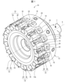
- FIG. 1 is a schematic perspective view of a rotary tool according to embodiments of the present disclosure
- FIG. FIG. 2 is a schematic view of the rotary tool shown in FIG. 1 as viewed from its tip side
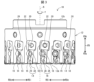
- FIG. 2 is a schematic side view of the rotary tool shown in FIG. 1
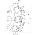
- FIG. 3 is an enlarged view of part IV in FIG. 2
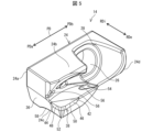
- 1 is a schematic perspective view of a cutting insert according to an embodiment of the present disclosure
- FIG. FIG. 6 is a schematic plan view of the cutting insert shown in FIG. 5
- FIG. 6 is a schematic plan view of the cutting insert shown in FIG. 5
- FIG. 6 is a schematic plan view of the cutting insert shown in FIG. 5
- FIG. 9 is a schematic enlarged view of part of the cutting insert shown in FIG.
- a cutting insert, a cutting tool, and a method for manufacturing a cut product according to embodiments of the present disclosure will be described in detail below with reference to the drawings.
- each drawing referred to below shows only the constituent elements necessary for explaining the embodiment in a simplified manner. Accordingly, cutting inserts and rotary tools according to embodiments of the present disclosure may include optional components not shown in the referenced figures. Also, the dimensions of the constituent elements in each drawing do not faithfully represent the dimensions of the actual constituent elements, the dimensional ratios of the respective members, and the like.
- the rotation axis means the rotation axis (rotational axis) of the rotary tool.
- the radially outer side is the direction away from the rotating shaft or the side away from the rotating shaft in the radial direction, and is synonymous with the outer peripheral side.
- the radially inner side is the direction toward or the side closer to the rotating shaft in the radial direction.
- a radial direction is a direction perpendicular to the axis of rotation.
- Orthogonality is not limited to strict orthogonality, but means that an error of about ⁇ 5 degrees is allowed.
- Parallelism is not limited to strict parallelism, but means that an error of about ⁇ 5 degrees is allowed.
- the positional relationship of each part of the cutting insert is defined based on the state in which the cutting insert is held (fixed) in the pocket of the holder for the sake of convenience.
- FIG. 1 is a schematic perspective view of a rotary tool 10 according to an embodiment of the present disclosure.
- FIG. 2 is a schematic view of the rotary tool 10 shown in FIG. 1 as viewed from its tip side.
- 3 is a schematic side view of the rotary tool shown in FIG. 1.
- FIG. FIG. 4 is an enlarged view of part IV in FIG.
- the rotary tool 10 is used for milling a workpiece W (see FIG. 10 ), and is rotatable around a rotation axis S. is a tool.
- the rotary tool 10 may have a holder 12 attached to a spindle of a processing machine such as a milling machine, and a plurality of cutting inserts 14 held by the holder 12 .
- a holder 12 and a cutting insert 14 are used in the rotary tool 10 .
- the holder 12 may have a cylindrical shape extending along the rotation axis S from the front end 12a to the rear end 12b.
- materials for the holder 12 include metals such as stainless steel, carbon steel, cast iron, and aluminum alloys.
- a plurality of pockets 16 may be provided at intervals in the circumferential direction on the outer peripheral surface of the holder 12 .
- the plurality of pockets 16 may be equally spaced in the circumferential direction, or may be unevenly spaced in the circumferential direction.
- a plurality of pockets 16 may be located on the tip 12a side of the holder 12 .
- the number of pockets 16 may be one.
- the tip PDa side of the pocket 16 in the direction PD parallel to the rotation axis S may be open.
- a radially outer RDe of the pocket 16 may be open.
- the pocket 16 may have a bottom surface 16a located on the radially inner side RDi, and a first inner side surface 16b and a second inner side surface 16c rising from both sides of the bottom surface 16a toward the radially outer side RDo.
- the first inner surface 16b of each pocket 16 may be positioned forward in the rotational direction T, in other words, on the rotational direction T side.
- the second inner surface 16c of each pocket 16 may be located rearward in the direction of rotation T, in other words on the opposite side of the direction of rotation T.
- the second inner side surface 16c of each pocket 16 may have a curved shape (convex shape) projecting forward in the rotation direction T. As shown in FIG. In other words, the second inner side surface 16c of each pocket 16 may have a convex portion 16d that protrudes forward in the rotational direction T. As shown in FIG.
- a cutting insert 14 may be positioned in each pocket 16 of the holder 12, as in the examples shown in FIGS.
- the cutting inserts 14 may be located only in selected pockets 16 in the holder 12 .
- the cutting insert 14 may also be fixed in the pocket 16 of the holder 12 by a fixing screw 18 .
- the cutting insert 14 may be secured in the pocket 16 of the holder 12 by a clamping member.
- the rotary tool 10 may have an adjustment mechanism 20 for adjusting the position of the cutting insert 14 with respect to the pocket 16 of the holder 12.
- the adjustment mechanism 20 may be located adjacent the cutting insert 14 in the pocket 16 of the holder 12 .
- the adjustment mechanism 20 may be fixed in the pocket 16 of the holder 12 by a fixing screw 22 .
- FIG. 5 is a schematic perspective view of a cutting insert 14 according to an embodiment of the present disclosure.
- 6 to 8 are schematic plan views of the cutting insert 14 shown in FIG. 5, respectively.
- FIG. 6 is a plan view (side view) viewed from the radially outer side RDe toward the rotation axis S.
- FIG. 7 is a plan view of the cutting insert 14 shown in FIG. 5 as seen from the front in the rotation direction T.
- FIG. 8 is a plan view (front view) of the cutting insert 14 shown in FIG. 5 as seen from the tip side along the rotation axis S.
- FIG. 5 is a schematic perspective view of a cutting insert 14 according to an embodiment of the present disclosure.
- 6 to 8 are schematic plan views of the cutting insert 14 shown in FIG. 5, respectively.
- FIG. 6 is a plan view (side view) viewed from the radially outer side RDe toward the rotation axis S.
- FIG. 7 is a plan view of the cutting insert 14 shown in FIG. 5 as seen from the front
- a cutting insert 14 may have a base portion 24 for mounting in a pocket 16 of a holder 12, as in the examples shown in FIGS.
- the base portion 24 may have a concave portion that opens toward the radially outer side RDe and the distal end PDa side in the direction PD parallel to the rotation axis S.
- the base portion 24 may have a main wall portion 24a that can come into contact with the bottom surface 16a of the pocket 16 of the holder 12 .
- the base portion 24 may have a first outer wall portion 24 b facing the first inner side surface 16 b of the pocket 16 of the holder 12 .
- the first outer wall portion 24b of the base portion 24 may extend radially outward RDe from the main wall portion 24a.
- the base portion 24 may have a second outer wall portion 24c that can abut against the second inner side surface 16c of the pocket 16 of the holder 12 .
- the second outer wall portion 24c of the base portion 24 may extend radially outward from the main wall portion 24a.
- the second outer wall portion 24c of the base portion 24 may be positioned rearward in the rotational direction T with respect to the first outer wall portion 24b.
- the base portion 24 may have a rising wall portion 24d rising from the second outer wall portion 24c to the first outer wall portion 24b on the side of the rear end PDb in the direction PD parallel to the rotation axis S.
- the main wall portion 24a, the first outer wall portion 24b, the second outer wall portion 24c, and the rising wall 24d are parts forming the outer edge surface of the base portion 24, and each have a thickness.
- the base portion 24 may have through holes 26 for inserting the fixing screws 22 .
- the through hole 26 may be open to the radially inner side RDi and the radially outer side RDe.
- the opening of the radially inner side RDi of the through hole 26 may be located on the wall surface of the main wall portion 24a.
- the first outer wall portion 24 b of the base portion 24 may have a notch portion 28 for avoiding interference with the fixing screw 22 .
- the base portion 24 may have a first rearward surface 30 located rearward in the direction of rotation T, with the majority of the first rearward surface 30 extending from the second surface of the base portion 24 . It may be configured by the outer surface of the outer wall portion 24c.
- the first rear surface 30 of the base portion 24 may extend from the front end PDa side in the direction PD parallel to the rotation axis S to the rear end PDb side.
- a direction PD parallel to the rotation axis S is an example of a direction along the rotation axis S.
- the base portion 24 may be provided with a concave portion 32 that opens forward in the rotational direction T and radially outward RDe.
- the concave portion 32 may be positioned on the side of the tip PDa in the direction PD parallel to the rotation axis S and on the radially outer side RDe of the base portion 24 .
- the bottom surface of the recess 32 may be a first front surface 34A facing forward in the rotation direction T.
- the base portion 24 may have a first front face 34A facing forward in the rotational direction T.
- the first front surface 34A of the base portion 24 may be located on the side of the tip PDa in the direction PD parallel to the rotation axis S and on the radially outer side RDe of the base portion 24 .
- the base portion 24 may have a first end surface 36 located on the side of the tip PDa in the direction PD parallel to the rotation axis S.
- the first end surface 36 may be configured by the end surfaces of the main wall portion 24a, the first outer wall portion 24b, and the second outer wall portion 24c on the side of the tip PDa in the direction PD parallel to the rotation axis S.
- a first end face 36 of the base portion 24 may be connected to the first rear face 30 and the first front face 34A.
- Examples of materials for the base portion 24 include stainless steel, carbon steel, tool steel, and the like.
- the cutting insert 14 may have a cutting portion 38 that contacts the work material W for cutting.
- the cutting portion 38 may be joined to the first front surface 34A, which is the bottom surface of the concave portion 32 of the base portion 24, with a joining material such as brazing material.
- the recess 32 may have a lateral wall surface 34B located radially inward RDi with respect to the first front surface 34A, and the cutting portion 38 may be joined to the lateral wall surface 34B in addition to the first front surface 34A.
- the recessed portion 32 has a rear wall surface 34C located on the side of the rear end PDb in the direction PD parallel to the rotation axis S with respect to the first front surface 34A, and the cutting portion 38 includes the first front surface 34A and the side wall surfaces. It may be joined to the rear wall surface 34C in addition to 34B.
- the cutting portion 38 may have a substantially polygonal plate shape such as a substantially triangular plate shape.
- the cutting portion 38 may have a flat second rear surface 40 joined to the first front surface 34A of the base portion 24. As shown in FIGS. A second rear surface 40 of the cutting portion 38 may face rearward in the direction of rotation T. As shown in FIG. In other words, the second rear surface 40 of the cutting portion 38 may be positioned rearward in the rotational direction T of the cutting portion 38 .
- the cutting portion 38 may also have a second planar front surface 42 opposite the second rear surface 40 . A second front surface 42 of the cutting portion 38 may face forward in the direction of rotation T. As shown in FIG. In other words, the second front surface 42 of the cutting portion 38 may be positioned forward in the rotational direction T of the cutting portion 38 .
- the cutting portion 38 may have a second end face 44 located on the side of the tip PDa in the direction PD parallel to the rotation axis S. A second end surface 44 of the cutting portion 38 may be connected to the second posterior surface 40 and the second anterior surface 42 .
- the cutting portion 38 may also have an outer surface 46 located radially outward RDe. An outer surface 46 of the cutting portion 38 may be connected to the second posterior surface 40 and the second anterior surface 42 .
- the cutting portion 38 may have a bottom cutting edge 48 as a first cutting edge located at the intersection of the second front face 42 and the second end face 44 .
- the cutting portion 38 may have a peripheral cutting edge 50 as a second cutting edge located at the intersection of the second front surface 42 and the outer surface 46 .
- the bottom cutting edge 48 and the peripheral cutting edge 50 may be connected via the corner portion 52 .
- the corner portion 52 of the cutting portion 38 may function as a corner edge.
- Examples of materials for the cutting portion 38 include hard materials such as cBN (Cubic Boron Nitride) and PCD (PolyCrystalline Diamond).
- the surface of cutting portion 38 may be coated with a coating using chemical vapor deposition (CVD) or physical vapor deposition (PVD) techniques.
- Examples of materials for the coating include titanium carbide (TiC), titanium nitride (TiN), titanium carbonitride (TiCN), and alumina (Al 2 O 3 ).
- the base portion 24 may be provided with a chip pocket 54 for discharging chips.
- the recess 32 may be located within the chip pocket 54 .
- the chip pocket 54 may be positioned forward in the rotational direction T with respect to the cutting portion 38 .
- the base portion 24 may be provided with injection holes 56 for injecting coolant (cooling medium) toward the cutting portion 38 .
- the number of injection holes 56 may be one or more.
- the injection holes 56 may be connected to a coolant supply through coolant passages provided inside the holder 12 .
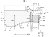
- FIG. 9 is a schematic enlarged view of part of the cutting insert 14 shown in FIG.
- the first end face 36 of the base portion 24 may have the first region F1.
- the first region F1 is located behind the second rear surface 40 of the cutting portion 38 in the rotation direction T when viewed from the side of the tip PDa in the direction PD parallel to the rotation axis S (see FIG. 1). portion and may be located on the radially outer side RDe of the base portion 24 .
- the first end surface 36 of the base portion 24 is behind the second front surface 42 of the cutting portion 38 in the rotation direction T when viewed from the side of the tip PDa in the direction PD parallel to the rotation axis S, It may have a second region F2 positioned radially inward RDi from the first region F1.
- different dots are attached to the first region F1 and the second region F2 of the first end face 36 of the base portion 24 .
- the first region F1 of the first end surface 36 of the base portion 24 rotates with respect to the second rear surface 40 of the cutting portion 38.
- a first portion F1p may be provided behind the direction T and sandwiched between the reference plane VP and the first rear surface 30, and the width of the area gradually increases toward the radially outer side RDe.
- the second region F2 of the first end surface 36 of the base portion 24 has a second portion F2p in which the width of the region sandwiched between the reference plane VP and the first rear surface 30 gradually increases toward the radially inner side RDi. may
- the width of the region sandwiched between the reference plane VP and the first rear surface 30 is the width in the direction perpendicular to the reference plane VP.
- the first region F1 may have portions other than the first portion F1p.
- the first region F1 may have a portion with a constant width in addition to the first portion F1p whose width gradually increases toward the radially outer side RDe.
- the constant width portion may be located radially inward RDi or radially outward RDe with respect to the first portion F1p.
- the second region F2 may have portions other than the second portion F2p.
- the second region F2 may have a constant width portion in addition to the second portion F2p whose width gradually increases toward the radially outer side RDe.
- the constant width portion may be positioned radially inward RDi or radially outward RDe with respect to the second portion F2p.
- the thickness of the portion of the holder 12 that supports the cutting insert 14 is ensured. easy to be
- the maximum value L1max of the width of the region sandwiched between the reference plane VP and the first rear surface 30 in the first region F1 of the first end surface 36 of the base portion 24 is the width of the reference plane VP and the first rear surface 30 in the second region F2. It may be smaller than the maximum value L2max of the width of the region sandwiched between the two. Further, the minimum value L1min of the width of the region sandwiched between the reference plane VP and the first rear surface 30 in the first region F1 of the first end surface 36 of the base portion 24 is the same as the reference plane VP and the first rear surface 30 in the second region F2. It may be larger than the minimum value L2min of the width of the area sandwiched between the planes 30 .
- the first end face 36 of the base portion 24 may have a groove 58 extending in the direction along the rotation axis S, as in the examples shown in FIGS.
- the groove 58 of the base portion 24 may extend in the direction PD parallel to the rotation axis S.
- the groove 58 of the base portion 24 may have a curved shape (concave shape) recessed forward in the rotation direction T.
- the first end surface 36 of the base portion 24 may have the groove 58 as a concave portion recessed forward in the rotation direction T.
- the groove 58 of the base portion 24 may be able to engage with the protrusion 16d of the pocket 16 of the holder 12 .
- the groove 58 of the base portion 24 may have a bottom portion 58b that is positioned furthest forward in the direction of rotation T.
- a bottom portion 58 b of the groove 58 of the base portion 24 may be positioned radially inward RDi of the cutting portion 38 .
- the radially outer RDe edge 58 e of the groove 58 in the base portion 24 may coincide with the radially outer RDe edge 30 e of the first rear surface 30 .
- the groove 58 in the base portion 24 may be spaced from the radially inner RDi edge 30i of the first rearward surface 30 .
- the base portion 24 When the first region F1 of the first end surface 36 of the base portion 24 has the first portion F1p as in the example shown in FIG. Sufficient thickness can be secured. Therefore, even if a large cutting load is applied to the outer peripheral side of the base portion 24, the base portion 24 is less likely to be damaged. As a result, the durability of the base portion 24 can be increased, and cutting conditions for a high rotational speed can be set.
- the durability of the base portion 24 against cutting load is enhanced.
- the second region F2 of the first end surface 36 of the base portion 24 has the second portion F2p
- having the second portion F2p even at a high rotational speed reduces scattering of the cutting insert 14 due to centrifugal force. can.
- the base portion 24 has both the first portion F1p and the second portion F2p
- the first rear surface 30 of the base portion 24 is recessed forward in the rotation direction T. As shown in FIG.
- the number of pockets 16 to which the cutting inserts 14 are attached can be increased while ensuring the durability of the portion of the holder 12 located behind the cutting insert 14 in the rotational direction and the base portion 24 . Therefore, more efficient processing can be performed.
- the cutting insert 14 is less likely to be displaced from the holder 12, and the machining accuracy of the cutting insert 14 is improved. can be enhanced.
- the first region F1 is the portion of the first end face 36 located behind the second rear face 40 in the rotational direction T
- the second region F2 is the first It is a portion adjacent to the region F1 on the radially inner side RDi.
- the first region F1 is a portion of the first end surface 36 located radially outside RDe of the bottom portion 58b of the groove 58 with respect to the bottom portion 58b
- the second region F2 is the first end surface. 36 located radially inward RDi from the bottom portion 58b.
- the bottom 58b of the groove 58 is positioned at the boundary between the first area F1 and the second area F2.
- the maximum width L1max of the first portion F1p in the first region F1 of the first end surface 36 of the base portion 24 is the maximum width of the second portion F2p in the second region F2. Let it be smaller than the value L2max. In this case, it is possible to sufficiently secure the thickness of the portion of the holder 12 that supports the cutting insert 14 on the outer peripheral side (radial direction outer side RDe). As a result, the holder 12 is less likely to be damaged, and the durability of the holder 12 can be further enhanced.
- the minimum value L1min of the width of the first portion F1p in the first region F1 of the first end face 36 of the base portion 24 is the minimum width of the second portion F2p in the second region F2.
- L2min is greater than the value L2min.
- the base portion 24 when the groove 58 of the base portion 24 has a curved shape (concave shape) recessed forward in the rotation direction T, the base portion 24 is formed in a curved shape (concave shape). It becomes difficult for the cutting load to concentrate on specific portions of the rear surface 30 and the first inner surface 16 b that is the bearing surface of the holder 12 . As a result, the cutting insert 14 and the holder 12 are less likely to break, and the durability of the cutting insert 14 and the holder 12 can be further enhanced.
- the thickness of the base portion 24 is thin. , the cutting load is less likely to be applied to the portion corresponding to the bottom portion 58b. Thereby, the cutting insert 14 becomes more difficult to be damaged, and the durability of the cutting insert 14 can be further improved.
- the width W2 of the second portion F2p in the radial direction may be larger than the width W1 of the first portion F1p in the radial direction.
- the maximum value L2max of the width of the second portion F2p is likely to be large while the inclination of the second portion F2p with respect to the reference plane VP is moderate. Since the inclination of the second portion F2p with respect to the reference plane VP is gentle, the cutting load transmitted from the cutting insert 14 to the holder 12 is less likely to be directed radially outward RDe, and the cutting insert 14 is stably held. Further, by ensuring a large maximum value L2max of the width of the second portion F2p, the cutting insert 14 is less likely to scatter due to centrifugal force.
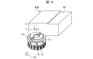
- FIGS. 10 to 12 are schematic diagrams illustrating the method for manufacturing a cut product according to the embodiment.
- the method for manufacturing a cut workpiece according to an embodiment of the present disclosure is a method for manufacturing a cut workpiece M, which is a workpiece W that has been machined. , a first step, a second step, and a third step.
- the first step is the step of rotating the rotary tool 10 .
- the second step is a step of bringing the rotating rotary tool 10 into contact with the workpiece W.
- the third step is the step of separating the rotary tool 10 from the workpiece W.
- Examples of the material of the work material W include aluminum alloy, stainless steel, carbon steel, alloy steel, cast iron, non-ferrous metals, and the like.
- the rotary tool 10 is moved in the direction of arrow FD while being rotated in the direction of rotation T to bring it closer to the workpiece W. Then, the cutting insert 14 of the rotating rotary tool 10 is moved in the direction of the arrow FD while being brought into contact with the work material W to be cut. As a result, the work W is cut (rolled) by the rotary tool 10, and a machined surface Wf is formed on the work as shown in FIG.
- the rotary tool 10 is moved in the direction of the arrow FD and separated from the work material W. As a result, the cutting of the work material W is completed, and the machined product M, which is the work material W that has been cut, can be manufactured. Since the rotary tool 10 has excellent cutting ability for the reason described above, it is possible to manufacture a machined workpiece M with excellent machining accuracy.
- the cutting insert 14 of the rotary tool 10 may be repeatedly brought into contact with different portions of the workpiece W while the rotary tool 10 is being rotated.
- the rotary tool 10 is brought closer to the workpiece W, but the workpiece W may be brought closer to the rotary tool 10 as long as the rotary tool 10 and the workpiece W are relatively close to each other. .
- the same operation is performed.
Landscapes
- Engineering & Computer Science (AREA)
- Mechanical Engineering (AREA)
- Milling Processes (AREA)
Priority Applications (4)
| Application Number | Priority Date | Filing Date | Title |
|---|---|---|---|
| DE112022005478.6T DE112022005478T5 (de) | 2021-11-17 | 2022-11-10 | Schneideinsatz, rotationswerkzeug und verfahren zur herstellung eines bearbeiteten produkts |
| JP2023561559A JP7759400B2 (ja) | 2021-11-17 | 2022-11-10 | 切削インサート、回転工具、及び切削加工物の製造方法 |
| US18/710,613 US20250010384A1 (en) | 2021-11-17 | 2022-11-10 | Cutting insert, rotary tool, and method for manufacturing machined product |
| CN202280075126.8A CN118234587A (zh) | 2021-11-17 | 2022-11-10 | 切削刀片、旋转刀具及切削加工物的制造方法 |
Applications Claiming Priority (2)
| Application Number | Priority Date | Filing Date | Title |
|---|---|---|---|
| JP2021187311 | 2021-11-17 | ||
| JP2021-187311 | 2021-11-17 |
Publications (1)
| Publication Number | Publication Date |
|---|---|
| WO2023090246A1 true WO2023090246A1 (ja) | 2023-05-25 |
Family
ID=86396937
Family Applications (1)
| Application Number | Title | Priority Date | Filing Date |
|---|---|---|---|
| PCT/JP2022/041890 Ceased WO2023090246A1 (ja) | 2021-11-17 | 2022-11-10 | 切削インサート、回転工具、及び切削加工物の製造方法 |
Country Status (5)
| Country | Link |
|---|---|
| US (1) | US20250010384A1 (https=) |
| JP (1) | JP7759400B2 (https=) |
| CN (1) | CN118234587A (https=) |
| DE (1) | DE112022005478T5 (https=) |
| WO (1) | WO2023090246A1 (https=) |
Cited By (1)
| Publication number | Priority date | Publication date | Assignee | Title |
|---|---|---|---|---|
| WO2025142180A1 (ja) * | 2023-12-28 | 2025-07-03 | 京セラ株式会社 | 切削工具及び切削加工物の製造方法 |
Citations (6)
| Publication number | Priority date | Publication date | Assignee | Title |
|---|---|---|---|---|
| JPH08509430A (ja) * | 1993-04-27 | 1996-10-08 | サンドビック アクティエボラーグ | 鋸歯付きカートリッジを具えたリングカッタ |
| JP2000135619A (ja) * | 1998-10-27 | 2000-05-16 | Sandvik Ab | チップブレ―ク機械加工用工具 |
| JP2004306245A (ja) * | 2003-03-26 | 2004-11-04 | Ngk Spark Plug Co Ltd | カッターボディおよび回転工具、並びに回転工具の組立方法 |
| JP2006521216A (ja) * | 2003-03-28 | 2006-09-21 | バレナイト リミティド ライアビリティ カンパニー | ミーリングカッタ及びそれに使用するためのインサートを支持するカートリッジ |
| WO2015163436A1 (ja) * | 2014-04-24 | 2015-10-29 | 京セラ株式会社 | 切削工具及び切削加工物の製造方法 |
| US20150328697A1 (en) * | 2012-12-28 | 2015-11-19 | Zhuzhou Cemented Carbide Cutting Tools Co., Ltd. | Rotary Cutting Tool with Accurate Positioning |
Family Cites Families (3)
| Publication number | Priority date | Publication date | Assignee | Title |
|---|---|---|---|---|
| JP2002011612A (ja) | 2000-06-23 | 2002-01-15 | Toshiba Tungaloy Co Ltd | 転削工具 |
| DE10312922B4 (de) | 2003-03-22 | 2006-02-16 | Walter Ag | Schneidplatte und Fräswerkzeug |
| JP2008023632A (ja) | 2006-07-19 | 2008-02-07 | Mitsubishi Materials Corp | 切削工具及びインサート |
-
2022
- 2022-11-10 JP JP2023561559A patent/JP7759400B2/ja active Active
- 2022-11-10 CN CN202280075126.8A patent/CN118234587A/zh active Pending
- 2022-11-10 DE DE112022005478.6T patent/DE112022005478T5/de active Pending
- 2022-11-10 WO PCT/JP2022/041890 patent/WO2023090246A1/ja not_active Ceased
- 2022-11-10 US US18/710,613 patent/US20250010384A1/en active Pending
Patent Citations (6)
| Publication number | Priority date | Publication date | Assignee | Title |
|---|---|---|---|---|
| JPH08509430A (ja) * | 1993-04-27 | 1996-10-08 | サンドビック アクティエボラーグ | 鋸歯付きカートリッジを具えたリングカッタ |
| JP2000135619A (ja) * | 1998-10-27 | 2000-05-16 | Sandvik Ab | チップブレ―ク機械加工用工具 |
| JP2004306245A (ja) * | 2003-03-26 | 2004-11-04 | Ngk Spark Plug Co Ltd | カッターボディおよび回転工具、並びに回転工具の組立方法 |
| JP2006521216A (ja) * | 2003-03-28 | 2006-09-21 | バレナイト リミティド ライアビリティ カンパニー | ミーリングカッタ及びそれに使用するためのインサートを支持するカートリッジ |
| US20150328697A1 (en) * | 2012-12-28 | 2015-11-19 | Zhuzhou Cemented Carbide Cutting Tools Co., Ltd. | Rotary Cutting Tool with Accurate Positioning |
| WO2015163436A1 (ja) * | 2014-04-24 | 2015-10-29 | 京セラ株式会社 | 切削工具及び切削加工物の製造方法 |
Cited By (1)
| Publication number | Priority date | Publication date | Assignee | Title |
|---|---|---|---|---|
| WO2025142180A1 (ja) * | 2023-12-28 | 2025-07-03 | 京セラ株式会社 | 切削工具及び切削加工物の製造方法 |
Also Published As
| Publication number | Publication date |
|---|---|
| DE112022005478T5 (de) | 2024-08-29 |
| US20250010384A1 (en) | 2025-01-09 |
| CN118234587A (zh) | 2024-06-21 |
| JPWO2023090246A1 (https=) | 2023-05-25 |
| JP7759400B2 (ja) | 2025-10-23 |
Similar Documents
| Publication | Publication Date | Title |
|---|---|---|
| WO2016203843A1 (ja) | 工具ボデーおよび切削工具 | |
| JP2008018515A (ja) | 切削インサート及び切削工具 | |
| JP6467049B2 (ja) | 切削工具及び切削加工物の製造方法 | |
| WO2016171174A1 (ja) | 切削工具及び切削加工物の製造方法 | |
| JP2008540147A (ja) | 工具用、特にフライス用の切削インサート | |
| WO2023090246A1 (ja) | 切削インサート、回転工具、及び切削加工物の製造方法 | |
| JP6950138B2 (ja) | フライス工具 | |
| CN115515740A (zh) | 钻头以及切削加工物的制造方法 | |
| JP2020104202A (ja) | 切削インサート、回転工具及び切削加工物の製造方法 | |
| JPWO2018221362A1 (ja) | エンドミル及び切削加工物の製造方法 | |
| JP7045460B2 (ja) | 切削工具及び切削加工物の製造方法 | |
| JP6467048B2 (ja) | 切削工具及び切削加工物の製造方法 | |
| JP2001150219A (ja) | スローアウェイ回転切削工具 | |
| JP7746403B2 (ja) | ホルダ、切削工具及び切削加工物の製造方法 | |
| JP7645174B2 (ja) | 切削工具及び切削加工物の製造方法 | |
| JP7223773B2 (ja) | 回転工具及び切削加工物の製造方法 | |
| JP7770537B2 (ja) | 回転工具及び切削加工物の製造方法 | |
| JP2018034215A (ja) | 切削工具及び切削加工物の製造方法 | |
| JP7004250B2 (ja) | 回転切削工具及び切りくず分断部材 | |
| WO2023058590A1 (ja) | 回転工具および切削加工物の製造方法 | |
| JP2004090153A (ja) | スローアウェイ式サイドカッター | |
| JP2024042457A (ja) | 切削工具及び切削加工物の製造方法 | |
| WO2023063127A1 (ja) | 切削工具及び切削加工物の製造方法 | |
| JP2025030995A (ja) | 回転工具及び切削加工物の製造方法 | |
| CN120981309A (zh) | 钻头及切削加工物的制造方法 |
Legal Events
| Date | Code | Title | Description |
|---|---|---|---|
| 121 | Ep: the epo has been informed by wipo that ep was designated in this application |
Ref document number: 22895528 Country of ref document: EP Kind code of ref document: A1 |
|
| ENP | Entry into the national phase |
Ref document number: 2023561559 Country of ref document: JP Kind code of ref document: A |
|
| WWE | Wipo information: entry into national phase |
Ref document number: 202280075126.8 Country of ref document: CN |
|
| WWE | Wipo information: entry into national phase |
Ref document number: 18710613 Country of ref document: US |
|
| WWE | Wipo information: entry into national phase |
Ref document number: 112022005478 Country of ref document: DE |
|
| 122 | Ep: pct application non-entry in european phase |
Ref document number: 22895528 Country of ref document: EP Kind code of ref document: A1 |