WO2023090246A1 - Cutting insert, rotary tool, and method for manufacturing cut product - Google Patents
Cutting insert, rotary tool, and method for manufacturing cut product Download PDFInfo
- Publication number
- WO2023090246A1 WO2023090246A1 PCT/JP2022/041890 JP2022041890W WO2023090246A1 WO 2023090246 A1 WO2023090246 A1 WO 2023090246A1 JP 2022041890 W JP2022041890 W JP 2022041890W WO 2023090246 A1 WO2023090246 A1 WO 2023090246A1
- Authority
- WO
- WIPO (PCT)
- Prior art keywords
- region
- cutting insert
- rear surface
- cutting
- rotary tool
- Prior art date
Links
Images


Classifications
-
- B—PERFORMING OPERATIONS; TRANSPORTING
- B23—MACHINE TOOLS; METAL-WORKING NOT OTHERWISE PROVIDED FOR
- B23C—MILLING
- B23C5/00—Milling-cutters
- B23C5/02—Milling-cutters characterised by the shape of the cutter
- B23C5/06—Face-milling cutters, i.e. having only or primarily a substantially flat cutting surface
-
- B—PERFORMING OPERATIONS; TRANSPORTING
- B23—MACHINE TOOLS; METAL-WORKING NOT OTHERWISE PROVIDED FOR
- B23C—MILLING
- B23C5/00—Milling-cutters
- B23C5/02—Milling-cutters characterised by the shape of the cutter
- B23C5/10—Shank-type cutters, i.e. with an integral shaft
-
- B—PERFORMING OPERATIONS; TRANSPORTING
- B23—MACHINE TOOLS; METAL-WORKING NOT OTHERWISE PROVIDED FOR
- B23C—MILLING
- B23C5/00—Milling-cutters
- B23C5/16—Milling-cutters characterised by physical features other than shape
- B23C5/20—Milling-cutters characterised by physical features other than shape with removable cutter bits or teeth or cutting inserts
- B23C5/22—Securing arrangements for bits or teeth or cutting inserts
- B23C5/24—Securing arrangements for bits or teeth or cutting inserts adjustable
Definitions
- the present disclosure relates to a cutting insert, a rotary tool, and a method for manufacturing a cut product used for milling a work material.
- the rotary tools described in Patent Documents 1 to 3 are known as rotary tools used when milling a work material made of metal or the like.
- the rotary tools described in Patent Documents 1 to 3 each have a holder and a cutting insert held by the holder.
- the cutting insert in the rotary tool described in Patent Document 3 has a base portion, which is called a cartridge in Patent Document 3, and a cutting portion, which is called a cutting edge tip in Patent Document 3.
- a cutting insert according to the present disclosure is a cutting insert used in a rotary tool rotatable around a rotation axis, and has a base portion and a cutting portion.
- the base portion has a first rear surface positioned rearward in the rotational direction of the rotary tool, a first front surface positioned radially outward and facing forward in the rotational direction, and a direction along the rotation axis. a first end face located on the distal side of the and connected to the first posterior face and the first anterior face.
- the cutting portion includes a second flat rear surface joined to the first front surface, a second flat front surface located opposite to the second rear surface, and a second flat front surface located on the tip side.
- the first end face includes a first region located rearward in the rotational direction and radially outward of the second rear face, and a second front face.
- the first end face has a second region positioned rearward in the rotational direction and radially inward of the first region.
- a virtual plane including the second rear surface is used as a reference surface, the width of the first area sandwiched between the reference surface and the first rear surface gradually increases radially outward. It has a first portion.
- the second area has a second portion in which the width of the area sandwiched between the reference surface and the first rear surface gradually increases radially inward.
- FIG. 1 is a schematic perspective view of a rotary tool according to embodiments of the present disclosure
- FIG. FIG. 2 is a schematic view of the rotary tool shown in FIG. 1 as viewed from its tip side
- FIG. 2 is a schematic side view of the rotary tool shown in FIG. 1
- FIG. 3 is an enlarged view of part IV in FIG. 2
- 1 is a schematic perspective view of a cutting insert according to an embodiment of the present disclosure
- FIG. FIG. 6 is a schematic plan view of the cutting insert shown in FIG. 5
- FIG. 6 is a schematic plan view of the cutting insert shown in FIG. 5
- FIG. 6 is a schematic plan view of the cutting insert shown in FIG. 5
- FIG. 9 is a schematic enlarged view of part of the cutting insert shown in FIG.
- a cutting insert, a cutting tool, and a method for manufacturing a cut product according to embodiments of the present disclosure will be described in detail below with reference to the drawings.
- each drawing referred to below shows only the constituent elements necessary for explaining the embodiment in a simplified manner. Accordingly, cutting inserts and rotary tools according to embodiments of the present disclosure may include optional components not shown in the referenced figures. Also, the dimensions of the constituent elements in each drawing do not faithfully represent the dimensions of the actual constituent elements, the dimensional ratios of the respective members, and the like.
- the rotation axis means the rotation axis (rotational axis) of the rotary tool.
- the radially outer side is the direction away from the rotating shaft or the side away from the rotating shaft in the radial direction, and is synonymous with the outer peripheral side.
- the radially inner side is the direction toward or the side closer to the rotating shaft in the radial direction.
- a radial direction is a direction perpendicular to the axis of rotation.
- Orthogonality is not limited to strict orthogonality, but means that an error of about ⁇ 5 degrees is allowed.
- Parallelism is not limited to strict parallelism, but means that an error of about ⁇ 5 degrees is allowed.
- the positional relationship of each part of the cutting insert is defined based on the state in which the cutting insert is held (fixed) in the pocket of the holder for the sake of convenience.
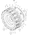
- FIG. 1 is a schematic perspective view of a rotary tool 10 according to an embodiment of the present disclosure.
- FIG. 2 is a schematic view of the rotary tool 10 shown in FIG. 1 as viewed from its tip side.
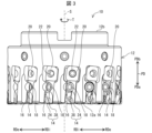
- 3 is a schematic side view of the rotary tool shown in FIG. 1.
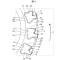
- FIG. FIG. 4 is an enlarged view of part IV in FIG.
- the rotary tool 10 is used for milling a workpiece W (see FIG. 10 ), and is rotatable around a rotation axis S. is a tool.
- the rotary tool 10 may have a holder 12 attached to a spindle of a processing machine such as a milling machine, and a plurality of cutting inserts 14 held by the holder 12 .
- a holder 12 and a cutting insert 14 are used in the rotary tool 10 .
- the holder 12 may have a cylindrical shape extending along the rotation axis S from the front end 12a to the rear end 12b.
- materials for the holder 12 include metals such as stainless steel, carbon steel, cast iron, and aluminum alloys.
- a plurality of pockets 16 may be provided at intervals in the circumferential direction on the outer peripheral surface of the holder 12 .
- the plurality of pockets 16 may be equally spaced in the circumferential direction, or may be unevenly spaced in the circumferential direction.
- a plurality of pockets 16 may be located on the tip 12a side of the holder 12 .
- the number of pockets 16 may be one.
- the tip PDa side of the pocket 16 in the direction PD parallel to the rotation axis S may be open.
- a radially outer RDe of the pocket 16 may be open.
- the pocket 16 may have a bottom surface 16a located on the radially inner side RDi, and a first inner side surface 16b and a second inner side surface 16c rising from both sides of the bottom surface 16a toward the radially outer side RDo.
- the first inner surface 16b of each pocket 16 may be positioned forward in the rotational direction T, in other words, on the rotational direction T side.
- the second inner surface 16c of each pocket 16 may be located rearward in the direction of rotation T, in other words on the opposite side of the direction of rotation T.
- the second inner side surface 16c of each pocket 16 may have a curved shape (convex shape) projecting forward in the rotation direction T. As shown in FIG. In other words, the second inner side surface 16c of each pocket 16 may have a convex portion 16d that protrudes forward in the rotational direction T. As shown in FIG.
- a cutting insert 14 may be positioned in each pocket 16 of the holder 12, as in the examples shown in FIGS.
- the cutting inserts 14 may be located only in selected pockets 16 in the holder 12 .
- the cutting insert 14 may also be fixed in the pocket 16 of the holder 12 by a fixing screw 18 .
- the cutting insert 14 may be secured in the pocket 16 of the holder 12 by a clamping member.
- the rotary tool 10 may have an adjustment mechanism 20 for adjusting the position of the cutting insert 14 with respect to the pocket 16 of the holder 12.
- the adjustment mechanism 20 may be located adjacent the cutting insert 14 in the pocket 16 of the holder 12 .
- the adjustment mechanism 20 may be fixed in the pocket 16 of the holder 12 by a fixing screw 22 .
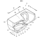
- FIG. 5 is a schematic perspective view of a cutting insert 14 according to an embodiment of the present disclosure.
- 6 to 8 are schematic plan views of the cutting insert 14 shown in FIG. 5, respectively.
- FIG. 6 is a plan view (side view) viewed from the radially outer side RDe toward the rotation axis S.
- FIG. 7 is a plan view of the cutting insert 14 shown in FIG. 5 as seen from the front in the rotation direction T.
- FIG. 8 is a plan view (front view) of the cutting insert 14 shown in FIG. 5 as seen from the tip side along the rotation axis S.
- FIG. 5 is a schematic perspective view of a cutting insert 14 according to an embodiment of the present disclosure.
- 6 to 8 are schematic plan views of the cutting insert 14 shown in FIG. 5, respectively.
- FIG. 6 is a plan view (side view) viewed from the radially outer side RDe toward the rotation axis S.
- FIG. 7 is a plan view of the cutting insert 14 shown in FIG. 5 as seen from the front
- a cutting insert 14 may have a base portion 24 for mounting in a pocket 16 of a holder 12, as in the examples shown in FIGS.
- the base portion 24 may have a concave portion that opens toward the radially outer side RDe and the distal end PDa side in the direction PD parallel to the rotation axis S.
- the base portion 24 may have a main wall portion 24a that can come into contact with the bottom surface 16a of the pocket 16 of the holder 12 .
- the base portion 24 may have a first outer wall portion 24 b facing the first inner side surface 16 b of the pocket 16 of the holder 12 .
- the first outer wall portion 24b of the base portion 24 may extend radially outward RDe from the main wall portion 24a.
- the base portion 24 may have a second outer wall portion 24c that can abut against the second inner side surface 16c of the pocket 16 of the holder 12 .
- the second outer wall portion 24c of the base portion 24 may extend radially outward from the main wall portion 24a.
- the second outer wall portion 24c of the base portion 24 may be positioned rearward in the rotational direction T with respect to the first outer wall portion 24b.
- the base portion 24 may have a rising wall portion 24d rising from the second outer wall portion 24c to the first outer wall portion 24b on the side of the rear end PDb in the direction PD parallel to the rotation axis S.
- the main wall portion 24a, the first outer wall portion 24b, the second outer wall portion 24c, and the rising wall 24d are parts forming the outer edge surface of the base portion 24, and each have a thickness.
- the base portion 24 may have through holes 26 for inserting the fixing screws 22 .
- the through hole 26 may be open to the radially inner side RDi and the radially outer side RDe.
- the opening of the radially inner side RDi of the through hole 26 may be located on the wall surface of the main wall portion 24a.
- the first outer wall portion 24 b of the base portion 24 may have a notch portion 28 for avoiding interference with the fixing screw 22 .
- the base portion 24 may have a first rearward surface 30 located rearward in the direction of rotation T, with the majority of the first rearward surface 30 extending from the second surface of the base portion 24 . It may be configured by the outer surface of the outer wall portion 24c.
- the first rear surface 30 of the base portion 24 may extend from the front end PDa side in the direction PD parallel to the rotation axis S to the rear end PDb side.
- a direction PD parallel to the rotation axis S is an example of a direction along the rotation axis S.
- the base portion 24 may be provided with a concave portion 32 that opens forward in the rotational direction T and radially outward RDe.
- the concave portion 32 may be positioned on the side of the tip PDa in the direction PD parallel to the rotation axis S and on the radially outer side RDe of the base portion 24 .
- the bottom surface of the recess 32 may be a first front surface 34A facing forward in the rotation direction T.
- the base portion 24 may have a first front face 34A facing forward in the rotational direction T.
- the first front surface 34A of the base portion 24 may be located on the side of the tip PDa in the direction PD parallel to the rotation axis S and on the radially outer side RDe of the base portion 24 .
- the base portion 24 may have a first end surface 36 located on the side of the tip PDa in the direction PD parallel to the rotation axis S.
- the first end surface 36 may be configured by the end surfaces of the main wall portion 24a, the first outer wall portion 24b, and the second outer wall portion 24c on the side of the tip PDa in the direction PD parallel to the rotation axis S.
- a first end face 36 of the base portion 24 may be connected to the first rear face 30 and the first front face 34A.
- Examples of materials for the base portion 24 include stainless steel, carbon steel, tool steel, and the like.
- the cutting insert 14 may have a cutting portion 38 that contacts the work material W for cutting.
- the cutting portion 38 may be joined to the first front surface 34A, which is the bottom surface of the concave portion 32 of the base portion 24, with a joining material such as brazing material.
- the recess 32 may have a lateral wall surface 34B located radially inward RDi with respect to the first front surface 34A, and the cutting portion 38 may be joined to the lateral wall surface 34B in addition to the first front surface 34A.
- the recessed portion 32 has a rear wall surface 34C located on the side of the rear end PDb in the direction PD parallel to the rotation axis S with respect to the first front surface 34A, and the cutting portion 38 includes the first front surface 34A and the side wall surfaces. It may be joined to the rear wall surface 34C in addition to 34B.
- the cutting portion 38 may have a substantially polygonal plate shape such as a substantially triangular plate shape.
- the cutting portion 38 may have a flat second rear surface 40 joined to the first front surface 34A of the base portion 24. As shown in FIGS. A second rear surface 40 of the cutting portion 38 may face rearward in the direction of rotation T. As shown in FIG. In other words, the second rear surface 40 of the cutting portion 38 may be positioned rearward in the rotational direction T of the cutting portion 38 .
- the cutting portion 38 may also have a second planar front surface 42 opposite the second rear surface 40 . A second front surface 42 of the cutting portion 38 may face forward in the direction of rotation T. As shown in FIG. In other words, the second front surface 42 of the cutting portion 38 may be positioned forward in the rotational direction T of the cutting portion 38 .
- the cutting portion 38 may have a second end face 44 located on the side of the tip PDa in the direction PD parallel to the rotation axis S. A second end surface 44 of the cutting portion 38 may be connected to the second posterior surface 40 and the second anterior surface 42 .
- the cutting portion 38 may also have an outer surface 46 located radially outward RDe. An outer surface 46 of the cutting portion 38 may be connected to the second posterior surface 40 and the second anterior surface 42 .
- the cutting portion 38 may have a bottom cutting edge 48 as a first cutting edge located at the intersection of the second front face 42 and the second end face 44 .
- the cutting portion 38 may have a peripheral cutting edge 50 as a second cutting edge located at the intersection of the second front surface 42 and the outer surface 46 .
- the bottom cutting edge 48 and the peripheral cutting edge 50 may be connected via the corner portion 52 .
- the corner portion 52 of the cutting portion 38 may function as a corner edge.
- Examples of materials for the cutting portion 38 include hard materials such as cBN (Cubic Boron Nitride) and PCD (PolyCrystalline Diamond).
- the surface of cutting portion 38 may be coated with a coating using chemical vapor deposition (CVD) or physical vapor deposition (PVD) techniques.
- Examples of materials for the coating include titanium carbide (TiC), titanium nitride (TiN), titanium carbonitride (TiCN), and alumina (Al 2 O 3 ).
- the base portion 24 may be provided with a chip pocket 54 for discharging chips.
- the recess 32 may be located within the chip pocket 54 .
- the chip pocket 54 may be positioned forward in the rotational direction T with respect to the cutting portion 38 .
- the base portion 24 may be provided with injection holes 56 for injecting coolant (cooling medium) toward the cutting portion 38 .
- the number of injection holes 56 may be one or more.
- the injection holes 56 may be connected to a coolant supply through coolant passages provided inside the holder 12 .
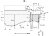
- FIG. 9 is a schematic enlarged view of part of the cutting insert 14 shown in FIG.
- the first end face 36 of the base portion 24 may have the first region F1.
- the first region F1 is located behind the second rear surface 40 of the cutting portion 38 in the rotation direction T when viewed from the side of the tip PDa in the direction PD parallel to the rotation axis S (see FIG. 1). portion and may be located on the radially outer side RDe of the base portion 24 .
- the first end surface 36 of the base portion 24 is behind the second front surface 42 of the cutting portion 38 in the rotation direction T when viewed from the side of the tip PDa in the direction PD parallel to the rotation axis S, It may have a second region F2 positioned radially inward RDi from the first region F1.
- different dots are attached to the first region F1 and the second region F2 of the first end face 36 of the base portion 24 .
- the first region F1 of the first end surface 36 of the base portion 24 rotates with respect to the second rear surface 40 of the cutting portion 38.
- a first portion F1p may be provided behind the direction T and sandwiched between the reference plane VP and the first rear surface 30, and the width of the area gradually increases toward the radially outer side RDe.
- the second region F2 of the first end surface 36 of the base portion 24 has a second portion F2p in which the width of the region sandwiched between the reference plane VP and the first rear surface 30 gradually increases toward the radially inner side RDi. may
- the width of the region sandwiched between the reference plane VP and the first rear surface 30 is the width in the direction perpendicular to the reference plane VP.
- the first region F1 may have portions other than the first portion F1p.
- the first region F1 may have a portion with a constant width in addition to the first portion F1p whose width gradually increases toward the radially outer side RDe.
- the constant width portion may be located radially inward RDi or radially outward RDe with respect to the first portion F1p.
- the second region F2 may have portions other than the second portion F2p.
- the second region F2 may have a constant width portion in addition to the second portion F2p whose width gradually increases toward the radially outer side RDe.
- the constant width portion may be positioned radially inward RDi or radially outward RDe with respect to the second portion F2p.
- the thickness of the portion of the holder 12 that supports the cutting insert 14 is ensured. easy to be
- the maximum value L1max of the width of the region sandwiched between the reference plane VP and the first rear surface 30 in the first region F1 of the first end surface 36 of the base portion 24 is the width of the reference plane VP and the first rear surface 30 in the second region F2. It may be smaller than the maximum value L2max of the width of the region sandwiched between the two. Further, the minimum value L1min of the width of the region sandwiched between the reference plane VP and the first rear surface 30 in the first region F1 of the first end surface 36 of the base portion 24 is the same as the reference plane VP and the first rear surface 30 in the second region F2. It may be larger than the minimum value L2min of the width of the area sandwiched between the planes 30 .
- the first end face 36 of the base portion 24 may have a groove 58 extending in the direction along the rotation axis S, as in the examples shown in FIGS.
- the groove 58 of the base portion 24 may extend in the direction PD parallel to the rotation axis S.
- the groove 58 of the base portion 24 may have a curved shape (concave shape) recessed forward in the rotation direction T.
- the first end surface 36 of the base portion 24 may have the groove 58 as a concave portion recessed forward in the rotation direction T.
- the groove 58 of the base portion 24 may be able to engage with the protrusion 16d of the pocket 16 of the holder 12 .
- the groove 58 of the base portion 24 may have a bottom portion 58b that is positioned furthest forward in the direction of rotation T.
- a bottom portion 58 b of the groove 58 of the base portion 24 may be positioned radially inward RDi of the cutting portion 38 .
- the radially outer RDe edge 58 e of the groove 58 in the base portion 24 may coincide with the radially outer RDe edge 30 e of the first rear surface 30 .
- the groove 58 in the base portion 24 may be spaced from the radially inner RDi edge 30i of the first rearward surface 30 .
- the base portion 24 When the first region F1 of the first end surface 36 of the base portion 24 has the first portion F1p as in the example shown in FIG. Sufficient thickness can be secured. Therefore, even if a large cutting load is applied to the outer peripheral side of the base portion 24, the base portion 24 is less likely to be damaged. As a result, the durability of the base portion 24 can be increased, and cutting conditions for a high rotational speed can be set.
- the durability of the base portion 24 against cutting load is enhanced.
- the second region F2 of the first end surface 36 of the base portion 24 has the second portion F2p
- having the second portion F2p even at a high rotational speed reduces scattering of the cutting insert 14 due to centrifugal force. can.
- the base portion 24 has both the first portion F1p and the second portion F2p
- the first rear surface 30 of the base portion 24 is recessed forward in the rotation direction T. As shown in FIG.
- the number of pockets 16 to which the cutting inserts 14 are attached can be increased while ensuring the durability of the portion of the holder 12 located behind the cutting insert 14 in the rotational direction and the base portion 24 . Therefore, more efficient processing can be performed.
- the cutting insert 14 is less likely to be displaced from the holder 12, and the machining accuracy of the cutting insert 14 is improved. can be enhanced.
- the first region F1 is the portion of the first end face 36 located behind the second rear face 40 in the rotational direction T
- the second region F2 is the first It is a portion adjacent to the region F1 on the radially inner side RDi.
- the first region F1 is a portion of the first end surface 36 located radially outside RDe of the bottom portion 58b of the groove 58 with respect to the bottom portion 58b
- the second region F2 is the first end surface. 36 located radially inward RDi from the bottom portion 58b.
- the bottom 58b of the groove 58 is positioned at the boundary between the first area F1 and the second area F2.
- the maximum width L1max of the first portion F1p in the first region F1 of the first end surface 36 of the base portion 24 is the maximum width of the second portion F2p in the second region F2. Let it be smaller than the value L2max. In this case, it is possible to sufficiently secure the thickness of the portion of the holder 12 that supports the cutting insert 14 on the outer peripheral side (radial direction outer side RDe). As a result, the holder 12 is less likely to be damaged, and the durability of the holder 12 can be further enhanced.
- the minimum value L1min of the width of the first portion F1p in the first region F1 of the first end face 36 of the base portion 24 is the minimum width of the second portion F2p in the second region F2.
- L2min is greater than the value L2min.
- the base portion 24 when the groove 58 of the base portion 24 has a curved shape (concave shape) recessed forward in the rotation direction T, the base portion 24 is formed in a curved shape (concave shape). It becomes difficult for the cutting load to concentrate on specific portions of the rear surface 30 and the first inner surface 16 b that is the bearing surface of the holder 12 . As a result, the cutting insert 14 and the holder 12 are less likely to break, and the durability of the cutting insert 14 and the holder 12 can be further enhanced.
- the thickness of the base portion 24 is thin. , the cutting load is less likely to be applied to the portion corresponding to the bottom portion 58b. Thereby, the cutting insert 14 becomes more difficult to be damaged, and the durability of the cutting insert 14 can be further improved.
- the width W2 of the second portion F2p in the radial direction may be larger than the width W1 of the first portion F1p in the radial direction.
- the maximum value L2max of the width of the second portion F2p is likely to be large while the inclination of the second portion F2p with respect to the reference plane VP is moderate. Since the inclination of the second portion F2p with respect to the reference plane VP is gentle, the cutting load transmitted from the cutting insert 14 to the holder 12 is less likely to be directed radially outward RDe, and the cutting insert 14 is stably held. Further, by ensuring a large maximum value L2max of the width of the second portion F2p, the cutting insert 14 is less likely to scatter due to centrifugal force.
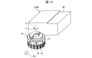
- FIGS. 10 to 12 are schematic diagrams illustrating the method for manufacturing a cut product according to the embodiment.
- the method for manufacturing a cut workpiece according to an embodiment of the present disclosure is a method for manufacturing a cut workpiece M, which is a workpiece W that has been machined. , a first step, a second step, and a third step.
- the first step is the step of rotating the rotary tool 10 .
- the second step is a step of bringing the rotating rotary tool 10 into contact with the workpiece W.
- the third step is the step of separating the rotary tool 10 from the workpiece W.
- Examples of the material of the work material W include aluminum alloy, stainless steel, carbon steel, alloy steel, cast iron, non-ferrous metals, and the like.
- the rotary tool 10 is moved in the direction of arrow FD while being rotated in the direction of rotation T to bring it closer to the workpiece W. Then, the cutting insert 14 of the rotating rotary tool 10 is moved in the direction of the arrow FD while being brought into contact with the work material W to be cut. As a result, the work W is cut (rolled) by the rotary tool 10, and a machined surface Wf is formed on the work as shown in FIG.
- the rotary tool 10 is moved in the direction of the arrow FD and separated from the work material W. As a result, the cutting of the work material W is completed, and the machined product M, which is the work material W that has been cut, can be manufactured. Since the rotary tool 10 has excellent cutting ability for the reason described above, it is possible to manufacture a machined workpiece M with excellent machining accuracy.
- the cutting insert 14 of the rotary tool 10 may be repeatedly brought into contact with different portions of the workpiece W while the rotary tool 10 is being rotated.
- the rotary tool 10 is brought closer to the workpiece W, but the workpiece W may be brought closer to the rotary tool 10 as long as the rotary tool 10 and the workpiece W are relatively close to each other. .
- the same operation is performed.
Abstract
The present invention increases the durability of a base portion to set a cutting condition with a large feeding amount. A first end face of the base portion comprises, when seen from the tip-end side in a direction along a rotational axis: a first region positioned rearwardly in a rotational direction and radially outside with respect to a second rear face of a cutting portion; and a second region positioned rearwardly in the rotational direction with respect to a second front face of the cutting portion and radially inside of the first region. When a virtual plane including the second rear face is a reference surface, the first region includes a first portion in which the width of a region sandwiched between the reference surface and a first rear face of the base portion gradually increases radially outward, and the second region includes a second portion in which the width of a region sandwiched between the reference surface and the first rear face gradually increases radially inward.
Description
本開示は、被削材の転削加工に用いられる切削インサート、回転工具、及び切削加工物の製造方法に関する。
The present disclosure relates to a cutting insert, a rotary tool, and a method for manufacturing a cut product used for milling a work material.
金属等からなる被削材を転削加工する際に用いられる回転工具として、例えば、特許文献1から3に記載の回転工具が知られる。特許文献1から3に記載の回転工具は、それぞれ、ホルダと、このホルダに保持される切削インサートと、を有する。特許文献3に記載の回転工具における切削インサートは、特許文献3ではカートリッジと称する基体部と、特許文献3では切刃チップと称する切削部と、を有する。
For example, the rotary tools described in Patent Documents 1 to 3 are known as rotary tools used when milling a work material made of metal or the like. The rotary tools described in Patent Documents 1 to 3 each have a holder and a cutting insert held by the holder. The cutting insert in the rotary tool described in Patent Document 3 has a base portion, which is called a cartridge in Patent Document 3, and a cutting portion, which is called a cutting edge tip in Patent Document 3.
本開示に係る切削インサートは、回転軸の周りで回転可能な回転工具に用いられる切削インサートであって、基体部と、切削部と、を有する。前記基体部は、前記回転工具の回転方向の後方に位置する第1後方面と、径方向外側に位置し、前記回転方向の前方を向いた第1前方面と、前記回転軸に沿った方向における先端の側に位置し、前記第1後方面及び前記第1前方面に接続された第1端面と、を有する。前記切削部は、前記第1前方面に接合された平らな第2後方面と、前記第2後方面の反対に位置する平らな第2前方面と、前記先端の側に位置し、前記第2後方面及び前記第2前方面に接続された第2端面と、前記第2前方面と前記第2端面との交わりに位置する切刃と、を有する。前記第1端面は、前記先端の側から見た場合に、前記第2後方面に対して前記回転方向の後方であって、径方向外側に位置する第1領域と、前記第2前方面に対して前記回転方向の後方であって、前記第1領域よりも径方向内側に位置する第2領域と、を有する。前記第2後方面を含む仮想平面を基準面とした場合に、前記第1領域は、前記基準面及び前記第1後方面に挟まれた領域の幅が径方向外側に向かって徐々に大きくなる第1部分を有する。前記第2領域は、前記基準面及び前記第1後方面に挟まれた領域の幅が径方向内側に向かって徐々に大きくなる第2部分を有する。
A cutting insert according to the present disclosure is a cutting insert used in a rotary tool rotatable around a rotation axis, and has a base portion and a cutting portion. The base portion has a first rear surface positioned rearward in the rotational direction of the rotary tool, a first front surface positioned radially outward and facing forward in the rotational direction, and a direction along the rotation axis. a first end face located on the distal side of the and connected to the first posterior face and the first anterior face. The cutting portion includes a second flat rear surface joined to the first front surface, a second flat front surface located opposite to the second rear surface, and a second flat front surface located on the tip side. It has a second end face connected to two rear faces and the second front face, and a cutting edge located at the intersection of the second front face and the second end face. When viewed from the tip side, the first end face includes a first region located rearward in the rotational direction and radially outward of the second rear face, and a second front face. On the other hand, it has a second region positioned rearward in the rotational direction and radially inward of the first region. When a virtual plane including the second rear surface is used as a reference surface, the width of the first area sandwiched between the reference surface and the first rear surface gradually increases radially outward. It has a first portion. The second area has a second portion in which the width of the area sandwiched between the reference surface and the first rear surface gradually increases radially inward.
以下、本開示の実施形態に係る切削インサート、切削工具、及び切削加工物の製造方法について、図面を用いて詳細に説明する。但し、以下で参照する各図は、説明の便宜上、実施形態を説明する上で必要な構成要素のみを簡略化して示したものである。従って、本開示の実施形態に係る切削インサート及び回転工具は、参照する各図に示されていない任意の構成要素を備え得る。また、各図中の構成要素の寸法は、実際の構成要素の寸法および各部材の寸法比率等を忠実に表したものではない。
A cutting insert, a cutting tool, and a method for manufacturing a cut product according to embodiments of the present disclosure will be described in detail below with reference to the drawings. However, for convenience of explanation, each drawing referred to below shows only the constituent elements necessary for explaining the embodiment in a simplified manner. Accordingly, cutting inserts and rotary tools according to embodiments of the present disclosure may include optional components not shown in the referenced figures. Also, the dimensions of the constituent elements in each drawing do not faithfully represent the dimensions of the actual constituent elements, the dimensional ratios of the respective members, and the like.
本開示において、回転軸とは、回転工具の回転軸(回転軸心)のことである。径方向外側とは、径方向のうち回転軸から遠ざかる方向又は遠ざかる側のことであり、外周側と同義である。径方向内側とは、径方向のうち回転軸に近づく方向又は近づく側のことである。径方向とは、回転軸に対して直交する方向のことである。直交とは、厳密な直交に限るものでなく、±5度程度の誤差を許容する意である。平行とは、厳密な平行に限るものでなく、±5度程度の誤差を許容する意である。また、本開示において、切削インサートの各部位等の位置関係は、便宜上、切削インサートがホルダのポケットに保持(固定)された状態を基準として規定している。
In the present disclosure, the rotation axis means the rotation axis (rotational axis) of the rotary tool. The radially outer side is the direction away from the rotating shaft or the side away from the rotating shaft in the radial direction, and is synonymous with the outer peripheral side. The radially inner side is the direction toward or the side closer to the rotating shaft in the radial direction. A radial direction is a direction perpendicular to the axis of rotation. Orthogonality is not limited to strict orthogonality, but means that an error of about ±5 degrees is allowed. Parallelism is not limited to strict parallelism, but means that an error of about ±5 degrees is allowed. In addition, in the present disclosure, the positional relationship of each part of the cutting insert is defined based on the state in which the cutting insert is held (fixed) in the pocket of the holder for the sake of convenience.
<回転工具>
図1から図4を参照して、本開示の実施形態に係る回転工具10について説明する。図1は、本開示の実施形態に係る回転工具10の模式的な斜視図である。図2は、図1に示す回転工具10をその先端側から見た模式的な図である。図3は、図1に示す回転工具の模式的な側面図である。図4は、図2におけるIV部の拡大図である。 <Rotary tool>
Arotary tool 10 according to an embodiment of the present disclosure will be described with reference to FIGS. 1 to 4. FIG. FIG. 1 is a schematic perspective view of a rotary tool 10 according to an embodiment of the present disclosure. FIG. 2 is a schematic view of the rotary tool 10 shown in FIG. 1 as viewed from its tip side. 3 is a schematic side view of the rotary tool shown in FIG. 1. FIG. FIG. 4 is an enlarged view of part IV in FIG.
図1から図4を参照して、本開示の実施形態に係る回転工具10について説明する。図1は、本開示の実施形態に係る回転工具10の模式的な斜視図である。図2は、図1に示す回転工具10をその先端側から見た模式的な図である。図3は、図1に示す回転工具の模式的な側面図である。図4は、図2におけるIV部の拡大図である。 <Rotary tool>
A
図1から図3に示す例のように、本開示の実施形態に係る回転工具10は、被削材W(図10参照)の転削加工に用いられ、回転軸Sの周りに回転可能な工具である。回転工具10は、フライス盤等の加工機の主軸に装着されるホルダ12と、ホルダ12に保持される複数の切削インサート14と、を有してもよい。ホルダ12及び切削インサート14は、回転工具10に用いられる。
As in the examples shown in FIGS. 1 to 3 , the rotary tool 10 according to the embodiment of the present disclosure is used for milling a workpiece W (see FIG. 10 ), and is rotatable around a rotation axis S. is a tool. The rotary tool 10 may have a holder 12 attached to a spindle of a processing machine such as a milling machine, and a plurality of cutting inserts 14 held by the holder 12 . A holder 12 and a cutting insert 14 are used in the rotary tool 10 .
ホルダ12は、回転軸Sに沿って先端12aから後端12bにかけて延びた円柱形状であってもよい。ホルダ12の材質としては、例えば、ステンレス鋼、炭素鋼、鋳鉄、アルミ合金等の金属等が挙げられる。ホルダ12の外周面には、複数のポケット16が周方向に間隔を空けて設けられてもよい。複数のポケット16は、周方向に等間隔に配置されてもよく、又は周方向に不等間隔に配置されてもよい。複数のポケット16は、ホルダ12の先端12aの側に位置してもよい。ポケット16の数は、1つであってもよい。
The holder 12 may have a cylindrical shape extending along the rotation axis S from the front end 12a to the rear end 12b. Examples of materials for the holder 12 include metals such as stainless steel, carbon steel, cast iron, and aluminum alloys. A plurality of pockets 16 may be provided at intervals in the circumferential direction on the outer peripheral surface of the holder 12 . The plurality of pockets 16 may be equally spaced in the circumferential direction, or may be unevenly spaced in the circumferential direction. A plurality of pockets 16 may be located on the tip 12a side of the holder 12 . The number of pockets 16 may be one.
図3から図4に示す例のように、ポケット16における回転軸Sに平行な方向PDの先端PDaの側は、開口されてもよい。ポケット16の径方向外側RDeは、開口されてもよい。ポケット16は、径方向内側RDiに位置する底面16aと、底面16aの両側から径方向外側RDoに向かって立ち上がる第1内側面16b及び第2内側面16cと、を有してもよい。各ポケット16の第1内側面16bは、回転方向Tの前方、換言すれば回転方向Tの側に位置してもよい。各ポケット16の第2内側面16cは、回転方向Tの後方、換言すれば回転方向Tの反対の側に位置してもよい。各ポケット16の第2内側面16cは、回転方向Tの前方に向かって突出した湾曲形状(凸形状)であってもよい。換言すれば、各ポケット16の第2内側面16cは、回転方向Tの前方向に突出した凸部16dを有してもよい。
As in the examples shown in FIGS. 3 and 4, the tip PDa side of the pocket 16 in the direction PD parallel to the rotation axis S may be open. A radially outer RDe of the pocket 16 may be open. The pocket 16 may have a bottom surface 16a located on the radially inner side RDi, and a first inner side surface 16b and a second inner side surface 16c rising from both sides of the bottom surface 16a toward the radially outer side RDo. The first inner surface 16b of each pocket 16 may be positioned forward in the rotational direction T, in other words, on the rotational direction T side. The second inner surface 16c of each pocket 16 may be located rearward in the direction of rotation T, in other words on the opposite side of the direction of rotation T. The second inner side surface 16c of each pocket 16 may have a curved shape (convex shape) projecting forward in the rotation direction T. As shown in FIG. In other words, the second inner side surface 16c of each pocket 16 may have a convex portion 16d that protrudes forward in the rotational direction T. As shown in FIG.
図1から図3に示す例のように、ホルダ12の各ポケット16には、切削インサート14が位置してもよい。切削インサート14は、ホルダ12における選択した1つ又は複数のポケット16にのみ位置してもよい。また、切削インサート14は、固定ネジ18によってホルダ12のポケット16に固定されてもよい。切削インサート14は、クランプ部材によってホルダ12のポケット16に固定されてもよい。
A cutting insert 14 may be positioned in each pocket 16 of the holder 12, as in the examples shown in FIGS. The cutting inserts 14 may be located only in selected pockets 16 in the holder 12 . The cutting insert 14 may also be fixed in the pocket 16 of the holder 12 by a fixing screw 18 . The cutting insert 14 may be secured in the pocket 16 of the holder 12 by a clamping member.
回転工具10は、ホルダ12のポケット16に対する切削インサート14の位置を調整するための調整機構20を有してもよい。調整機構20は、ホルダ12のポケット16における切削インサート14と隣接する位置に位置してもよい。調整機構20は、固定ネジ22によってホルダ12のポケット16に固定されてもよい。
The rotary tool 10 may have an adjustment mechanism 20 for adjusting the position of the cutting insert 14 with respect to the pocket 16 of the holder 12. The adjustment mechanism 20 may be located adjacent the cutting insert 14 in the pocket 16 of the holder 12 . The adjustment mechanism 20 may be fixed in the pocket 16 of the holder 12 by a fixing screw 22 .
<切削インサート>
図5から図8を参照して、本開示の実施形態に係る切削インサート14の構成について説明する。図5は、本開示の実施形態に係る切削インサート14の模式的な斜視図である。図6から図8は、それぞれ図5に示す切削インサート14の模式的な平面図である。図6は、径方向外側RDeから回転軸Sに向かう方向で見た平面図(側面図)である。図7は、図5に示す切削インサート14を回転方向Tの前方から見た平面図である。図8は、図5に示す切削インサート14を回転軸Sに沿って先端の側から見た平面図(正面図)である。 <Cutting insert>
The configuration of the cutting insert 14 according to the embodiment of the present disclosure will be described with reference to FIGS. 5 to 8. FIG. FIG. 5 is a schematic perspective view of a cuttinginsert 14 according to an embodiment of the present disclosure. 6 to 8 are schematic plan views of the cutting insert 14 shown in FIG. 5, respectively. FIG. 6 is a plan view (side view) viewed from the radially outer side RDe toward the rotation axis S. FIG. 7 is a plan view of the cutting insert 14 shown in FIG. 5 as seen from the front in the rotation direction T. FIG. 8 is a plan view (front view) of the cutting insert 14 shown in FIG. 5 as seen from the tip side along the rotation axis S. FIG.
図5から図8を参照して、本開示の実施形態に係る切削インサート14の構成について説明する。図5は、本開示の実施形態に係る切削インサート14の模式的な斜視図である。図6から図8は、それぞれ図5に示す切削インサート14の模式的な平面図である。図6は、径方向外側RDeから回転軸Sに向かう方向で見た平面図(側面図)である。図7は、図5に示す切削インサート14を回転方向Tの前方から見た平面図である。図8は、図5に示す切削インサート14を回転軸Sに沿って先端の側から見た平面図(正面図)である。 <Cutting insert>
The configuration of the cutting insert 14 according to the embodiment of the present disclosure will be described with reference to FIGS. 5 to 8. FIG. FIG. 5 is a schematic perspective view of a cutting
図5から図8に示す例のように、本開示の実施形態に係る切削インサート14は、ホルダ12のポケット16に取付けるための基体部24を有してもよい。基体部24は、径方向外側RDe及び回転軸Sに平行な方向PDの先端PDaの側に向かって開口する凹部を有してもよい。基体部24は、ホルダ12のポケット16の底面16aに当接可能な主壁部24aを有してもよい。
A cutting insert 14 according to embodiments of the present disclosure may have a base portion 24 for mounting in a pocket 16 of a holder 12, as in the examples shown in FIGS. The base portion 24 may have a concave portion that opens toward the radially outer side RDe and the distal end PDa side in the direction PD parallel to the rotation axis S. As shown in FIG. The base portion 24 may have a main wall portion 24a that can come into contact with the bottom surface 16a of the pocket 16 of the holder 12 .
基体部24は、ホルダ12のポケット16の第1内側面16bに対向する第1外壁部24bを有してもよい。基体部24の第1外壁部24bは、主壁部24aから径方向外側RDeに向かって延びてもよい。基体部24は、ホルダ12のポケット16の第2内側面16cに当接可能な第2外壁部24cを有してもよい。基体部24の第2外壁部24cは、主壁部24aから径方向外側に向かって延びてもよい。基体部24の第2外壁部24cは、第1外壁部24bに対して回転方向Tの後方に位置してもよい。また、基体部24は、回転軸Sに平行な方向PDの後端PDbの側において第2外壁部24cから第1外壁部24bに立ち上がる立ち上がり壁部24dを有してもよい。
The base portion 24 may have a first outer wall portion 24 b facing the first inner side surface 16 b of the pocket 16 of the holder 12 . The first outer wall portion 24b of the base portion 24 may extend radially outward RDe from the main wall portion 24a. The base portion 24 may have a second outer wall portion 24c that can abut against the second inner side surface 16c of the pocket 16 of the holder 12 . The second outer wall portion 24c of the base portion 24 may extend radially outward from the main wall portion 24a. The second outer wall portion 24c of the base portion 24 may be positioned rearward in the rotational direction T with respect to the first outer wall portion 24b. Further, the base portion 24 may have a rising wall portion 24d rising from the second outer wall portion 24c to the first outer wall portion 24b on the side of the rear end PDb in the direction PD parallel to the rotation axis S.
主壁部24a、第1外壁部24b、第2外壁部24c、及び立ち上がり壁24dは、それぞれ、基体部24における外縁面の構成部位であって、肉厚を有している。
The main wall portion 24a, the first outer wall portion 24b, the second outer wall portion 24c, and the rising wall 24d are parts forming the outer edge surface of the base portion 24, and each have a thickness.
基体部24は、固定ネジ22を挿通させるための貫通孔26を有してもよい。貫通孔26は、径方向内側RDi及び径方向外側RDeに対して開口されてもよい。貫通孔26における径方向内側RDiの開口は、主壁部24aの壁面に位置してもよい。また、基体部24の第1外壁部24bは、固定ネジ22との干渉を回避するための切欠部28を有してもよい。
The base portion 24 may have through holes 26 for inserting the fixing screws 22 . The through hole 26 may be open to the radially inner side RDi and the radially outer side RDe. The opening of the radially inner side RDi of the through hole 26 may be located on the wall surface of the main wall portion 24a. Also, the first outer wall portion 24 b of the base portion 24 may have a notch portion 28 for avoiding interference with the fixing screw 22 .
図8に示す例のように、基体部24は、回転方向Tの後方に位置する第1後方面30を有してもよく、第1後方面30の大部分は、基体部24の第2外壁部24cの外側面によって構成されてもよい。基体部24の第1後方面30は、回転軸Sに平行な方向PDの先端PDaの側から後端PDbの側にかけて延びてもよい。回転軸Sに平行な方向PDは、回転軸Sに沿った方向の一例である。
As in the example shown in FIG. 8 , the base portion 24 may have a first rearward surface 30 located rearward in the direction of rotation T, with the majority of the first rearward surface 30 extending from the second surface of the base portion 24 . It may be configured by the outer surface of the outer wall portion 24c. The first rear surface 30 of the base portion 24 may extend from the front end PDa side in the direction PD parallel to the rotation axis S to the rear end PDb side. A direction PD parallel to the rotation axis S is an example of a direction along the rotation axis S. FIG.
基体部24には、回転方向Tの前方及び径方向外側RDeに向かって開口した凹部32が設けられてもよい。凹部32は、回転軸Sに平行な方向PDの先端PDaの側であって、基体部24における径方向外側RDeに位置してもよい。凹部32の底面は、回転方向Tの前方を向いた第1前方面34Aであってもよい。換言すれば、基体部24は、回転方向Tの前方を向いた第1前方面34Aを有してもよい。基体部24の第1前方面34Aは、回転軸Sに平行な方向PDの先端PDaの側であって、基体部24における径方向外側RDeに位置してもよい。
The base portion 24 may be provided with a concave portion 32 that opens forward in the rotational direction T and radially outward RDe. The concave portion 32 may be positioned on the side of the tip PDa in the direction PD parallel to the rotation axis S and on the radially outer side RDe of the base portion 24 . The bottom surface of the recess 32 may be a first front surface 34A facing forward in the rotation direction T. As shown in FIG. In other words, the base portion 24 may have a first front face 34A facing forward in the rotational direction T. As shown in FIG. The first front surface 34A of the base portion 24 may be located on the side of the tip PDa in the direction PD parallel to the rotation axis S and on the radially outer side RDe of the base portion 24 .
基体部24は、回転軸Sに平行な方向PDの先端PDaの側に位置する第1端面36を有してもよい。第1端面36は、主壁部24a、第1外壁部24b、及び第2外壁部24cにおける回転軸Sに平行な方向PDの先端PDaの側の端面によって構成されてもよい。基体部24の第1端面36は、第1後方面30及び第1前方面34Aに接続されてもよい。
The base portion 24 may have a first end surface 36 located on the side of the tip PDa in the direction PD parallel to the rotation axis S. The first end surface 36 may be configured by the end surfaces of the main wall portion 24a, the first outer wall portion 24b, and the second outer wall portion 24c on the side of the tip PDa in the direction PD parallel to the rotation axis S. A first end face 36 of the base portion 24 may be connected to the first rear face 30 and the first front face 34A.
基体部24の材質としては、例えば、ステンレス鋼、炭素鋼又は工具鋼等が挙げられる。
Examples of materials for the base portion 24 include stainless steel, carbon steel, tool steel, and the like.
切削インサート14は、被削材Wに接触して切削加工を行う切削部38を有してもよい。切削部38は、例えば、ろう材等の接合材によって基体部24の凹部32の底面である第1前方面34Aに接合されてもよい。凹部32が第1前方面34Aに対して径方向内側RDiに位置する横壁面34Bを有し、切削部38が、第1前方面34Aに加えて横壁面34Bに接合されてもよい。また、凹部32が第1前方面34Aに対して回転軸Sに平行な方向PDの後端PDbの側に位置する後壁面34Cを有し、切削部38が、第1前方面34A及び横壁面34Bに加えて後壁面34Cに接合されてもよい。切削部38は、略三角板形状等の略多角板形状であってもよい。
The cutting insert 14 may have a cutting portion 38 that contacts the work material W for cutting. The cutting portion 38 may be joined to the first front surface 34A, which is the bottom surface of the concave portion 32 of the base portion 24, with a joining material such as brazing material. The recess 32 may have a lateral wall surface 34B located radially inward RDi with respect to the first front surface 34A, and the cutting portion 38 may be joined to the lateral wall surface 34B in addition to the first front surface 34A. Further, the recessed portion 32 has a rear wall surface 34C located on the side of the rear end PDb in the direction PD parallel to the rotation axis S with respect to the first front surface 34A, and the cutting portion 38 includes the first front surface 34A and the side wall surfaces. It may be joined to the rear wall surface 34C in addition to 34B. The cutting portion 38 may have a substantially polygonal plate shape such as a substantially triangular plate shape.
図5から図8に示す例のように、切削部38は、基体部24の第1前方面34Aに接合された平らな第2後方面40を有してもよい。切削部38の第2後方面40は、回転方向Tの後方を向いてもよい。換言すれば、切削部38の第2後方面40は、切削部38における回転方向Tの後方に位置してもよい。また、切削部38は、第2後方面40の反対に位置する平らな第2前方面42を有してもよい。切削部38の第2前方面42は、回転方向Tの前方を向いてもよい。換言すれば、切削部38の第2前方面42は、切削部38における回転方向Tの前方に位置してもよい。
As in the examples shown in FIGS. 5-8, the cutting portion 38 may have a flat second rear surface 40 joined to the first front surface 34A of the base portion 24. As shown in FIGS. A second rear surface 40 of the cutting portion 38 may face rearward in the direction of rotation T. As shown in FIG. In other words, the second rear surface 40 of the cutting portion 38 may be positioned rearward in the rotational direction T of the cutting portion 38 . The cutting portion 38 may also have a second planar front surface 42 opposite the second rear surface 40 . A second front surface 42 of the cutting portion 38 may face forward in the direction of rotation T. As shown in FIG. In other words, the second front surface 42 of the cutting portion 38 may be positioned forward in the rotational direction T of the cutting portion 38 .
切削部38は、回転軸Sに平行な方向PDの先端PDaの側に位置する第2端面44を有してもよい。切削部38の第2端面44は、第2後方面40及び第2前方面42に接続されてもよい。また、切削部38は、径方向外側RDeに位置する外側面46を有してもよい。切削部38の外側面46は、第2後方面40及び第2前方面42に接続されてもよい。
The cutting portion 38 may have a second end face 44 located on the side of the tip PDa in the direction PD parallel to the rotation axis S. A second end surface 44 of the cutting portion 38 may be connected to the second posterior surface 40 and the second anterior surface 42 . The cutting portion 38 may also have an outer surface 46 located radially outward RDe. An outer surface 46 of the cutting portion 38 may be connected to the second posterior surface 40 and the second anterior surface 42 .
切削部38は、第2前方面42と第2端面44との交わりに位置する第1切刃としての底刃48を有してもよい。切削部38は、第2前方面42と外側面46との交わりに位置する第2切刃としての外周刃50を有してもよい。底刃48と外周刃50は、コーナ部52を介して繋がっていてもよい。切削部38のコーナ部52は、コーナ刃としての機能を有してもよい。
The cutting portion 38 may have a bottom cutting edge 48 as a first cutting edge located at the intersection of the second front face 42 and the second end face 44 . The cutting portion 38 may have a peripheral cutting edge 50 as a second cutting edge located at the intersection of the second front surface 42 and the outer surface 46 . The bottom cutting edge 48 and the peripheral cutting edge 50 may be connected via the corner portion 52 . The corner portion 52 of the cutting portion 38 may function as a corner edge.
切削部38の材質としては、例えば、cBN(Cubic Boron Nitride)、PCD(PolyCrystalline Diamond)等の硬質材料が挙げられる。切削部38の表面には、化学蒸着(CVD)法又は物理蒸着(PVD)法を用いて被膜がコーティングされていてもよい。被膜の材質としては、例えば、炭化チタン(TiC)、窒化チタン(TiN)、炭窒化チタン(TiCN)、又はアルミナ(Al2O3)等が挙げられる。
Examples of materials for the cutting portion 38 include hard materials such as cBN (Cubic Boron Nitride) and PCD (PolyCrystalline Diamond). The surface of cutting portion 38 may be coated with a coating using chemical vapor deposition (CVD) or physical vapor deposition (PVD) techniques. Examples of materials for the coating include titanium carbide (TiC), titanium nitride (TiN), titanium carbonitride (TiCN), and alumina (Al 2 O 3 ).
図5から図8に示す例のように、基体部24には、切屑を排出するための切屑ポケット54が設けられてもよい。凹部32は、切屑ポケット54内に位置してもよい。切屑ポケット54は、切削部38に対して回転方向Tの前方に位置してもよい。また、基体部24には、切削部38に向かってクーラント(冷却媒体)を噴射するための噴射孔56が設けられてもよい。噴射孔56の数は、1つ又は複数であってもよい。噴射孔56は、ホルダ12の内部に設けられたクーラント通路を介してクーラント供給源に接続されてもよい。
As in the examples shown in FIGS. 5 to 8, the base portion 24 may be provided with a chip pocket 54 for discharging chips. The recess 32 may be located within the chip pocket 54 . The chip pocket 54 may be positioned forward in the rotational direction T with respect to the cutting portion 38 . Further, the base portion 24 may be provided with injection holes 56 for injecting coolant (cooling medium) toward the cutting portion 38 . The number of injection holes 56 may be one or more. The injection holes 56 may be connected to a coolant supply through coolant passages provided inside the holder 12 .
図6、図8、及び図9を参照して、本開示の実施形態に係る切削インサート14の他の構成について説明する。図9は、図8に示す切削インサート14の一部の模式的な拡大図である。
Another configuration of the cutting insert 14 according to the embodiment of the present disclosure will be described with reference to FIGS. FIG. 9 is a schematic enlarged view of part of the cutting insert 14 shown in FIG.
図8及び図9に示す例のように、基体部24の第1端面36は、第1領域F1を有してもよい。第1領域F1は、回転軸S(図1参照)に平行な方向PDの先端PDaの側から見た場合に、切削部38の第2後方面40に対して回転方向Tの後方に位置する部分を含み、基体部24における径方向外側RDeに位置してもよい。基体部24の第1端面36は、回転軸Sに平行な方向PDの先端PDaの側から見た場合に、切削部38の第2前方面42に対して回転方向Tの後方であって、第1領域F1よりも径方向内側RDiに位置する第2領域F2を有してもよい。図9に示す例においては、基体部24の第1端面36の第1領域F1及び第2領域F2に異なるドットを付している。
As in the examples shown in FIGS. 8 and 9, the first end face 36 of the base portion 24 may have the first region F1. The first region F1 is located behind the second rear surface 40 of the cutting portion 38 in the rotation direction T when viewed from the side of the tip PDa in the direction PD parallel to the rotation axis S (see FIG. 1). portion and may be located on the radially outer side RDe of the base portion 24 . The first end surface 36 of the base portion 24 is behind the second front surface 42 of the cutting portion 38 in the rotation direction T when viewed from the side of the tip PDa in the direction PD parallel to the rotation axis S, It may have a second region F2 positioned radially inward RDi from the first region F1. In the example shown in FIG. 9, different dots are attached to the first region F1 and the second region F2 of the first end face 36 of the base portion 24 .
切削部38の第2後方面40を含む仮想平面を基準面VPとした場合に、基体部24の第1端面36の第1領域F1は、切削部38の第2後方面40に対して回転方向Tの後方であって、基準面VP及び第1後方面30に挟まれた領域の幅が径方向外側RDeに向かって徐々に大きくなる第1部分F1pを有してもよい。基体部24の第1端面36の第2領域F2は、基準面VP及び第1後方面30に挟まれた領域の幅が径方向内側RDiに向かって徐々に大きくなる第2部分F2pを有してもよい。基準面VP及び第1後方面30に挟まれた領域の幅は、基準面VPに直交する方向の幅である。
When a virtual plane including the second rear surface 40 of the cutting portion 38 is the reference plane VP, the first region F1 of the first end surface 36 of the base portion 24 rotates with respect to the second rear surface 40 of the cutting portion 38. A first portion F1p may be provided behind the direction T and sandwiched between the reference plane VP and the first rear surface 30, and the width of the area gradually increases toward the radially outer side RDe. The second region F2 of the first end surface 36 of the base portion 24 has a second portion F2p in which the width of the region sandwiched between the reference plane VP and the first rear surface 30 gradually increases toward the radially inner side RDi. may The width of the region sandwiched between the reference plane VP and the first rear surface 30 is the width in the direction perpendicular to the reference plane VP.
第1領域F1が第1部分F1p以外の部分を有してもよい。例えば、第1領域F1が、径方向外側RDeに向かって幅が徐々に大きくなる第1部分F1pに加えて、幅が一定の部分を有してもよい。幅が一定の部分は、第1部分F1pに対して径方向内側RDiに位置してもよく、また、径方向外側RDeに位置してもよい。
The first region F1 may have portions other than the first portion F1p. For example, the first region F1 may have a portion with a constant width in addition to the first portion F1p whose width gradually increases toward the radially outer side RDe. The constant width portion may be located radially inward RDi or radially outward RDe with respect to the first portion F1p.
第2領域F2が第2部分F2p以外の部分を有してもよい。例えば、第2領域F2が、径方向外側RDeに向かって幅が徐々に大きくなる第2部分F2pに加えて、幅が一定の部分を有してもよい。幅が一定の部分は、第2部分F2pに対して径方向内側RDiに位置してもよく、また、径方向外側RDeに位置してもよい。例えば、図9に示すように、上記した幅が一定の部分が第2部分F2pに対して径方向内側RDiに位置する場合には、ホルダ12における切削インサート14を支持する部分の肉厚が確保されやすい。
The second region F2 may have portions other than the second portion F2p. For example, the second region F2 may have a constant width portion in addition to the second portion F2p whose width gradually increases toward the radially outer side RDe. The constant width portion may be positioned radially inward RDi or radially outward RDe with respect to the second portion F2p. For example, as shown in FIG. 9, when the portion having the constant width is positioned radially inward RDi with respect to the second portion F2p, the thickness of the portion of the holder 12 that supports the cutting insert 14 is ensured. easy to be
基体部24の第1端面36の第1領域F1における基準面VP及び第1後方面30に挟まれた領域の幅の最大値L1maxは、第2領域F2における基準面VP及び第1後方面30に挟まれた領域の幅の最大値L2maxよりも小さくてもよい。また、基体部24の第1端面36の第1領域F1における基準面VP及び第1後方面30に挟まれた領域の幅の最小値L1minは、第2領域F2における基準面VP及び第1後方面30に挟まれた領域の幅の最小値L2minよりも大きくてもよい。
The maximum value L1max of the width of the region sandwiched between the reference plane VP and the first rear surface 30 in the first region F1 of the first end surface 36 of the base portion 24 is the width of the reference plane VP and the first rear surface 30 in the second region F2. It may be smaller than the maximum value L2max of the width of the region sandwiched between the two. Further, the minimum value L1min of the width of the region sandwiched between the reference plane VP and the first rear surface 30 in the first region F1 of the first end surface 36 of the base portion 24 is the same as the reference plane VP and the first rear surface 30 in the second region F2. It may be larger than the minimum value L2min of the width of the area sandwiched between the planes 30 .
図6、図8、及び図9に示す例のように、基体部24の第1端面36は、回転軸Sに沿った方向に延びた溝58を有してもよい。基体部24の溝58は、回転軸Sに平行な方向PDに延びてもよい。基体部24の溝58は、回転方向Tの前方に向かって窪んだ湾曲形状(凹形状)であってもよい。換言すれば、基体部24の第1端面36は、回転方向Tの前方に向かって窪んだ凹部としての溝58を有してもよい。基体部24の溝58は、ホルダ12のポケット16の凸部16dに係合可能であってもよい。
The first end face 36 of the base portion 24 may have a groove 58 extending in the direction along the rotation axis S, as in the examples shown in FIGS. The groove 58 of the base portion 24 may extend in the direction PD parallel to the rotation axis S. The groove 58 of the base portion 24 may have a curved shape (concave shape) recessed forward in the rotation direction T. As shown in FIG. In other words, the first end surface 36 of the base portion 24 may have the groove 58 as a concave portion recessed forward in the rotation direction T. As shown in FIG. The groove 58 of the base portion 24 may be able to engage with the protrusion 16d of the pocket 16 of the holder 12 .
基体部24の溝58は、回転方向Tの最も前方に位置する底部58bを有してもよい。基体部24の溝58の底部58bは、切削部38よりも径方向内側RDiに位置してもよい。基体部24の溝58の径方向外側RDeの縁部58eは、第1後方面30の径方向外側RDeの縁部30eに一致してもよい。基体部24の溝58は、第1後方面30の径方向内側RDiの縁部30iから離れてもよい。
The groove 58 of the base portion 24 may have a bottom portion 58b that is positioned furthest forward in the direction of rotation T. A bottom portion 58 b of the groove 58 of the base portion 24 may be positioned radially inward RDi of the cutting portion 38 . The radially outer RDe edge 58 e of the groove 58 in the base portion 24 may coincide with the radially outer RDe edge 30 e of the first rear surface 30 . The groove 58 in the base portion 24 may be spaced from the radially inner RDi edge 30i of the first rearward surface 30 .
図9に示す例のように、基体部24の第1端面36の第1領域F1が第1部分F1pを有している場合には、基体部24の径方向外側RDe(外周側)での厚みを十分に確保することができる。そのため、基体部24の外周側に大きな切削負荷が加わっても、基体部24が破損し難くなる。これにより、基体部24の耐久性を高めて、高い回転速度の切削条件を設定することができる。
When the first region F1 of the first end surface 36 of the base portion 24 has the first portion F1p as in the example shown in FIG. Sufficient thickness can be secured. Therefore, even if a large cutting load is applied to the outer peripheral side of the base portion 24, the base portion 24 is less likely to be damaged. As a result, the durability of the base portion 24 can be increased, and cutting conditions for a high rotational speed can be set.
図8及び図9に示す例のように、基体部24の第1端面36の第1領域F1が第1部分F1pを有する場合には、切削負荷に対する基体部24の耐久性が高められる。また、基体部24の第1端面36の第2領域F2が第2部分F2pを有する場合には、高い回転速度下でも第2部分F2pを有する事で、遠心力による切削インサート14の飛散を低減できる。そして、基体部24がこれら第1部分F1p及び第2部分F2pを兼ね備える場合には、基体部24の第1後方面30が回転方向Tの前方に向かって窪んだ凹形状になる。これにより、ホルダ12における切削インサート14に対して回転方向の後方に位置する部分及び基体部24の耐久性を確保しつつ、切削インサート14が取り付けられるポケット16の数を多くすることができる。そのため、より高能率な加工を行うことができる。
As in the examples shown in FIGS. 8 and 9, when the first region F1 of the first end face 36 of the base portion 24 has the first portion F1p, the durability of the base portion 24 against cutting load is enhanced. In addition, when the second region F2 of the first end surface 36 of the base portion 24 has the second portion F2p, having the second portion F2p even at a high rotational speed reduces scattering of the cutting insert 14 due to centrifugal force. can. When the base portion 24 has both the first portion F1p and the second portion F2p, the first rear surface 30 of the base portion 24 is recessed forward in the rotation direction T. As shown in FIG. As a result, the number of pockets 16 to which the cutting inserts 14 are attached can be increased while ensuring the durability of the portion of the holder 12 located behind the cutting insert 14 in the rotational direction and the base portion 24 . Therefore, more efficient processing can be performed.
また、基体部24の第1後方面30が回転方向Tの前方に向かって窪んだ凹形状になるため、ホルダ12に対して切削インサート14が位置ずれし難くなり、切削インサート14の加工精度を高めることができる。
In addition, since the first rear surface 30 of the base portion 24 has a concave shape that is recessed forward in the rotation direction T, the cutting insert 14 is less likely to be displaced from the holder 12, and the machining accuracy of the cutting insert 14 is improved. can be enhanced.
上記した通り、第1領域F1は、第1端面36のうち第2後方面40に対して回転方向Tの後方に位置する部分であり、第2領域F2は、第1端面36のうち第1領域F1に対して径方向内側RDiにおいて隣接する部分である。特に、図9に示す例においては、第1領域F1が溝58の底部58bを基準として、第1端面36における底部58bよりも径方向外側RDeに位置する部分、第2領域F2が第1端面36における底部58bよりも径方向内側RDiに位置する部分となっている。言い換えれば、第1領域F1及び第2領域F2の境界に溝58の底部58bが位置している。
As described above, the first region F1 is the portion of the first end face 36 located behind the second rear face 40 in the rotational direction T, and the second region F2 is the first It is a portion adjacent to the region F1 on the radially inner side RDi. In particular, in the example shown in FIG. 9, the first region F1 is a portion of the first end surface 36 located radially outside RDe of the bottom portion 58b of the groove 58 with respect to the bottom portion 58b, and the second region F2 is the first end surface. 36 located radially inward RDi from the bottom portion 58b. In other words, the bottom 58b of the groove 58 is positioned at the boundary between the first area F1 and the second area F2.
図8及び図9の例に示すように、基体部24の第1端面36の第1領域F1における第1部分F1pの幅の最大値L1maxが第2領域F2における第2部分F2pの幅の最大値L2maxよりも小さいとする。この場合には、外周側(径方向外側RDe)においてホルダ12における切削インサート14を支持する部分の厚みを十分に確保することができる。これにより、ホルダ12がより破損し難くなり、ホルダ12の耐久性をより高めることができる。
As shown in the examples of FIGS. 8 and 9, the maximum width L1max of the first portion F1p in the first region F1 of the first end surface 36 of the base portion 24 is the maximum width of the second portion F2p in the second region F2. Let it be smaller than the value L2max. In this case, it is possible to sufficiently secure the thickness of the portion of the holder 12 that supports the cutting insert 14 on the outer peripheral side (radial direction outer side RDe). As a result, the holder 12 is less likely to be damaged, and the durability of the holder 12 can be further enhanced.
図8及び図9の例に示すように、基体部24の第1端面36の第1領域F1における第1部分F1pの幅の最小値L1minが第2領域F2における第2部分F2pの幅の最小値L2minよりも大きいとする。この場合には、外周側において基体部24における切削部38を支持する部分の厚みを十分に確保することができる。ホルダ12の外周側での厚みを十分に確保することができる。これにより、ホルダ12がより破損し難くなり、ホルダ12の耐久性をより高めることができる。
As shown in the examples of FIGS. 8 and 9, the minimum value L1min of the width of the first portion F1p in the first region F1 of the first end face 36 of the base portion 24 is the minimum width of the second portion F2p in the second region F2. Suppose it is greater than the value L2min. In this case, it is possible to sufficiently secure the thickness of the portion supporting the cutting portion 38 in the base portion 24 on the outer peripheral side. A sufficient thickness can be ensured on the outer peripheral side of the holder 12 . As a result, the holder 12 is less likely to be damaged, and the durability of the holder 12 can be further enhanced.
図6、図8、及び図9に示す例のように、基体部24の溝58が回転方向Tの前方に向かって窪んだ湾曲形状(凹形状)である場合には、基体部24の第1後方面30及びホルダ12の座面である第1内側面16bの特定の個所に切削負荷が集中し難くなる。これにより、切削インサート14及びホルダ12がより破損し難くなり、切削インサート14及びホルダ12の耐久性をより高めることができる。
As in the examples shown in FIGS. 6, 8, and 9, when the groove 58 of the base portion 24 has a curved shape (concave shape) recessed forward in the rotation direction T, the base portion 24 is formed in a curved shape (concave shape). It becomes difficult for the cutting load to concentrate on specific portions of the rear surface 30 and the first inner surface 16 b that is the bearing surface of the holder 12 . As a result, the cutting insert 14 and the holder 12 are less likely to break, and the durability of the cutting insert 14 and the holder 12 can be further enhanced.
図8及び図9の例に示すように、基体部24の溝58の底部58bが切削部38よりも径方向内側RDiに位置している場合には、基体部24の厚みの薄い箇所である、底部58bに対応する箇所に切削負荷が加わり難くなる。これにより、切削インサート14が更に破損し難くなり、切削インサート14の耐久性を更に高めることができる。
As shown in the examples of FIGS. 8 and 9, when the bottom portion 58b of the groove 58 of the base portion 24 is located radially inward RDi of the cutting portion 38, the thickness of the base portion 24 is thin. , the cutting load is less likely to be applied to the portion corresponding to the bottom portion 58b. Thereby, the cutting insert 14 becomes more difficult to be damaged, and the durability of the cutting insert 14 can be further improved.
図6、図8、及び図9に示す例のように、基体部24の溝58が回転軸Sに平行な方向PDに延びている場合には、ホルダ12に対して切削インサート14がより位置ずれし難くなり、切削インサート14の加工精度をより高めることができる。
6, 8, and 9, when the groove 58 of the base portion 24 extends in the direction PD parallel to the rotation axis S, the cutting insert 14 is positioned further with respect to the holder 12. It becomes difficult to shift, and the machining accuracy of the cutting insert 14 can be further improved.
図8及び図9の例に示すように、基体部24の溝58の径方向外側RDeの縁部58eが第1後方面30の径方向外側RDeの縁部30eに一致している場合には、外周側(径方向外側RDe)において基体部の厚みを十分に確保することできる。これにより、切削インサート14が更に破損し難くなり、切削インサート14の耐久性を更に高めることができる。
8 and 9, when the radially outer RDe edge 58e of the groove 58 of the base portion 24 coincides with the radially outer RDe edge 30e of the first rear surface 30, , the thickness of the base portion can be sufficiently secured on the outer peripheral side (radial direction outer side RDe). Thereby, the cutting insert 14 becomes more difficult to be damaged, and the durability of the cutting insert 14 can be further improved.
図8及び図9の例に示すように、基体部24の溝58が第1後方面30の径方向内側RDiの縁部30iから離れている場合には、径方向内側RDiにおいてホルダ12における切削インサート14を支持する部分の厚みが過度に小さくことを回避することができる。これにより、ホルダ12がより破損し難くなり、ホルダ12の耐久性をより高めることができる。
As shown in the examples of FIGS. 8 and 9, if groove 58 in base portion 24 is spaced from edge 30i of radially inner RDi of first rear surface 30, cutting in holder 12 at radially inner RDi An excessively small thickness of the part supporting the insert 14 can be avoided. As a result, the holder 12 is less likely to be damaged, and the durability of the holder 12 can be further enhanced.
図8及び図9の例に示すように、径方向における第2部分F2pの幅W2が、径方向における第1部分F1pの幅W1より大きくてもよい。この場合には、基準面VPに対する第2部分F2pの傾斜を緩やかにしつつ、第2部分F2pの幅の最大値L2maxが大きく確保されやすい。基準面VPに対する第2部分F2pの傾斜が緩やかであることによって、切削インサート14からホルダ12に伝わる切削負荷が径方向外側RDeに向かいにくく、切削インサート14が安定して保持される。また、第2部分F2pの幅の最大値L2maxが大きく確保されることによって、遠心力による切削インサート14の飛散が生じにくい。
As shown in the examples of FIGS. 8 and 9, the width W2 of the second portion F2p in the radial direction may be larger than the width W1 of the first portion F1p in the radial direction. In this case, the maximum value L2max of the width of the second portion F2p is likely to be large while the inclination of the second portion F2p with respect to the reference plane VP is moderate. Since the inclination of the second portion F2p with respect to the reference plane VP is gentle, the cutting load transmitted from the cutting insert 14 to the holder 12 is less likely to be directed radially outward RDe, and the cutting insert 14 is stably held. Further, by ensuring a large maximum value L2max of the width of the second portion F2p, the cutting insert 14 is less likely to scatter due to centrifugal force.
<切削加工部の製造方法>
図10から図12を参照して、実施形態に係る切削加工物の製造方法について説明する。図10から図12は、実施形態に係る切削加工物の製造方法を説明する模式図である。 <Manufacturing method of cutting part>
A method for manufacturing a cut product according to the embodiment will be described with reference to FIGS. 10 to 12 . 10 to 12 are schematic diagrams illustrating the method for manufacturing a cut product according to the embodiment.
図10から図12に示す例のように、本開示の実施形態に係る切削加工物の製造方法は、切削加工済みの被削材Wである切削加工物Mを製造するための方法であって、第1工程と、第2工程と、第3工程とを備えている。第1工程とは、回転工具10を回転させる工程のことである。第2工程とは、回転している回転工具10を被削材Wに接触させる工程のことである。第3工程とは、回転工具10を被削材Wから離す工程のことである。被削材Wの材質としては、例えば、アルミ合金、ステンレス鋼、炭素鋼、合金鋼、鋳鉄、又は非鉄金属等が挙げられる。そして、本実施形態に係る切削加工物の製造方法の具体的な内容は、次の通りである。
As in the examples shown in FIGS. 10 to 12, the method for manufacturing a cut workpiece according to an embodiment of the present disclosure is a method for manufacturing a cut workpiece M, which is a workpiece W that has been machined. , a first step, a second step, and a third step. The first step is the step of rotating the rotary tool 10 . The second step is a step of bringing the rotating rotary tool 10 into contact with the workpiece W. As shown in FIG. The third step is the step of separating the rotary tool 10 from the workpiece W. As shown in FIG. Examples of the material of the work material W include aluminum alloy, stainless steel, carbon steel, alloy steel, cast iron, non-ferrous metals, and the like. The specific details of the method for manufacturing a cut product according to this embodiment are as follows.
図10及び図11に示す例のように、回転工具10を回転方向Tに回転させつつ、矢印FDへ移動させて、被削材Wに近づける。そして、回転している回転工具10の切削インサート14を被削材Wに接触させながら、矢印FD方向へ移動させる。これにより、回転工具10によって被削材Wの切削加工(転削加工)が行われ、図12に示す例のように、被削材に加工面Wfが形成される。
As in the example shown in FIGS. 10 and 11, the rotary tool 10 is moved in the direction of arrow FD while being rotated in the direction of rotation T to bring it closer to the workpiece W. Then, the cutting insert 14 of the rotating rotary tool 10 is moved in the direction of the arrow FD while being brought into contact with the work material W to be cut. As a result, the work W is cut (rolled) by the rotary tool 10, and a machined surface Wf is formed on the work as shown in FIG.
その後、図12に示す例のように、回転工具10を矢印FD方向へ移動させて、被削材Wから離す。これにより、被削材Wの切削加工が終了し、切削加工済みの被削材Wである切削加工物Mを製造することができる。回転工具10が前述した理由から優れた切削能力を備えているので、加工精度に優れた切削加工物Mを製造することができる。
After that, as in the example shown in FIG. 12, the rotary tool 10 is moved in the direction of the arrow FD and separated from the work material W. As a result, the cutting of the work material W is completed, and the machined product M, which is the work material W that has been cut, can be manufactured. Since the rotary tool 10 has excellent cutting ability for the reason described above, it is possible to manufacture a machined workpiece M with excellent machining accuracy.
切削加工を継続する場合には、回転工具10を回転させた状態で、被削材Wの異なる箇所への回転工具10の切削インサート14による接触を繰り返せばよい。本実施形態では、回転工具10を被削材Wに近づけているが、回転工具10と被削材Wとが相対的に近づけばよいため、被削材Wを回転工具10に近づけてもよい。この点、回転工具10を被削材Wから離す場合も同じように行う。
In order to continue cutting, the cutting insert 14 of the rotary tool 10 may be repeatedly brought into contact with different portions of the workpiece W while the rotary tool 10 is being rotated. In the present embodiment, the rotary tool 10 is brought closer to the workpiece W, but the workpiece W may be brought closer to the rotary tool 10 as long as the rotary tool 10 and the workpiece W are relatively close to each other. . In this respect, when the rotary tool 10 is separated from the work material W, the same operation is performed.
以上、本開示に係る発明について、諸図面および実施例に基づいて説明してきた。しかし、本開示に係る発明は前述した各実施形態に限定されるものではない。すなわち、本開示に係る発明は本開示で示した範囲で種々の変更が可能であり、異なる実施形態にそれぞれ開示された技術的手段を適宜組み合わせて得られる実施形態についても本開示に係る発明の技術的範囲に含まれる。つまり、当業者であれば本開示に基づき種々の変形または修正を行うことが容易であることに注意されたい。また、これらの変形または修正は本開示の範囲に含まれることに留意されたい。
The invention according to the present disclosure has been described above based on various drawings and examples. However, the invention according to the present disclosure is not limited to each embodiment described above. That is, the invention according to the present disclosure can be variously modified within the scope shown in the present disclosure, and the embodiments obtained by appropriately combining the technical means disclosed in different embodiments can also be applied to the invention according to the present disclosure. Included in the technical scope. In other words, it should be noted that a person skilled in the art can easily make various variations or modifications based on this disclosure. Also, note that these variations or modifications are included within the scope of this disclosure.
10 回転工具
12 ホルダ
14 切削インサート
16 ポケット
16a 底面
16b 第1内側面
16c 第2内側面
16d 凸部
18 固定ネジ
20 調整機構
22 固定ネジ
24 基体部
24a 主壁部
24b 第1外壁部
24c 第2外壁部
24d 立ち上がり壁部
26 貫通孔
28 切欠部
30 第1後方面
30e 径方向外側の縁部
30i 径方向内側の縁部
32 凹部
34A 第1前方面
34B 横壁面
34C 後壁面
36 第1端面
38 切削部
40 第2後方面
42 第2前方面
44 第2端面
46 外側面
48 底刃(切刃)
50 外周刃(外周刃)
52 コーナ部
54 切屑ポケット
56 噴射孔
58 溝
58b 底部
58e 径方向外側の縁部
F1 第1領域
F1p 第1部分
F2 第2領域
F2p 第2部分 REFERENCE SIGNSLIST 10 rotary tool 12 holder 14 cutting insert 16 pocket 16a bottom surface 16b first inner side surface 16c second inner side surface 16d convex portion 18 fixing screw 20 adjusting mechanism 22 fixing screw 24 base portion 24a main wall portion 24b first outer wall portion 24c second outer wall Part 24d Rising wall 26 Through hole 28 Notch 30 First rear surface 30e Radial outer edge 30i Radial inner edge 32 Recess 34A First front surface 34B Side wall 34C Rear wall 36 First end surface 38 Cut portion 40 Second rear surface 42 Second front surface 44 Second end surface 46 Outer surface 48 Bottom edge (cutting edge)
50 Peripheral cutting edge (peripheral cutting edge)
52corner portion 54 chip pocket 56 injection hole 58 groove 58b bottom portion 58e radial outer edge portion F1 first region F1p first portion F2 second region F2p second portion
12 ホルダ
14 切削インサート
16 ポケット
16a 底面
16b 第1内側面
16c 第2内側面
16d 凸部
18 固定ネジ
20 調整機構
22 固定ネジ
24 基体部
24a 主壁部
24b 第1外壁部
24c 第2外壁部
24d 立ち上がり壁部
26 貫通孔
28 切欠部
30 第1後方面
30e 径方向外側の縁部
30i 径方向内側の縁部
32 凹部
34A 第1前方面
34B 横壁面
34C 後壁面
36 第1端面
38 切削部
40 第2後方面
42 第2前方面
44 第2端面
46 外側面
48 底刃(切刃)
50 外周刃(外周刃)
52 コーナ部
54 切屑ポケット
56 噴射孔
58 溝
58b 底部
58e 径方向外側の縁部
F1 第1領域
F1p 第1部分
F2 第2領域
F2p 第2部分 REFERENCE SIGNS
50 Peripheral cutting edge (peripheral cutting edge)
52
Claims (10)
- 回転軸の周りで回転可能な回転工具に用いられる切削インサートであって、
前記回転工具の回転方向の後方に位置する第1後方面と、
径方向外側に位置し、前記回転方向の前方を向いた第1前方面と、
前記回転軸に沿った方向における先端の側に位置し、前記第1後方面及び前記第1前方面に接続された第1端面と、
を有する基体部と、
前記第1前方面に接合された平らな第2後方面と、
前記第2後方面の反対に位置する平らな第2前方面と、
前記先端の側に位置し、前記第2後方面及び前記第2前方面に接続された第2端面と、
前記第2前方面と前記第2端面との交わりに位置する切刃と、
を有する切削部と、を有し、
前記第1端面は、前記先端の側から見た場合に、
前記第2後方面に対して前記回転方向の後方であって、径方向外側に位置する第1領域と、
前記第2前方面に対して前記回転方向の後方であって、前記第1領域よりも径方向内側に位置する第2領域と、を有し、
前記第2後方面を含む仮想平面を基準面とした場合に、
前記第1領域は、前記基準面及び前記第1後方面に挟まれた領域の幅が径方向外側に向かって徐々に大きくなる第1部分を有し、
前記第2領域は、前記基準面及び前記第1後方面に挟まれた領域の幅が径方向内側に向かって徐々に大きくなる第2部分を有する、切削インサート。 A cutting insert for use in a rotary tool rotatable around a rotary axis,
a first rear surface positioned rearward in the rotational direction of the rotary tool;
a first front face positioned radially outward and facing forward in the direction of rotation;
a first end surface located on the tip side in the direction along the rotation axis and connected to the first rear surface and the first front surface;
a base portion having
a flat second posterior surface joined to the first anterior surface;
a flat second anterior surface opposite the second posterior surface;
a second end surface located on the tip side and connected to the second rear surface and the second front surface;
a cutting edge positioned at the intersection of the second front surface and the second end surface;
and a cutting portion having
When the first end face is viewed from the tip side,
a first region located rearward in the rotational direction with respect to the second rear surface and radially outward;
a second region positioned rearward in the rotational direction with respect to the second front surface and radially inward of the first region;
When a virtual plane including the second rear surface is used as a reference plane,
The first region has a first portion in which the width of the region sandwiched between the reference surface and the first rear surface gradually increases radially outward,
The cutting insert, wherein the second region has a second portion in which the width of the region sandwiched between the reference surface and the first rear surface gradually increases radially inward. - 前記第1領域における前記基準面及び前記第1後方面に挟まれた領域の幅の最大値が、前記第2領域における前記基準面及び前記第1後方面に挟まれた領域の幅の最大値よりも小さい、請求項1に記載の切削インサート。 The maximum value of the width of the region sandwiched between the reference plane and the first rear surface in the first region is the maximum value of the width of the region sandwiched between the reference plane and the first rear surface in the second region. 2. The cutting insert according to claim 1, which is smaller than .
- 前記第1領域における前記基準面及び前記第1後方面に挟まれた領域の幅の最小値が、前記第2領域における前記基準面及び前記第1後方面に挟まれた領域の幅の最小値よりも大きい、請求項1又は2に記載の切削インサート。 The minimum value of the width of the region sandwiched between the reference surface and the first rear surface in the first region is the minimum value of the width of the region sandwiched between the reference surface and the first rear surface in the second region. 3. The cutting insert according to claim 1 or 2, which is larger than .
- 前記第1後方面は、前記回転軸に沿った方向に延びた溝を有し、
前記溝は、前記回転方向の前方に向かって窪んだ湾曲形状である、請求項1から3のいずれか1項に記載の切削インサート。 The first rear surface has a groove extending in a direction along the rotation axis,
The cutting insert according to any one of claims 1 to 3, wherein the groove has a curved shape that is recessed forward in the rotational direction. - 前記溝は、前記回転方向の最も前方に位置する底部を有し、
前記底部は、前記切削部よりも径方向内側に位置する、請求項4に記載の切削インサート。 The groove has a bottom portion positioned most forward in the direction of rotation,
The cutting insert according to claim 4, wherein the bottom portion is located radially inwardly of the cutting portion. - 前記溝は、前記回転軸に平行な方向に延びている、請求項4又は5に記載の切削インサート。 The cutting insert according to claim 4 or 5, wherein said groove extends in a direction parallel to said rotation axis.
- 前記溝の径方向外側の縁部は、前記第1後方面の径方向外側の縁部と一致している、請求項4から6のいずれか1項に記載の切削インサート。 The cutting insert according to any one of claims 4 to 6, wherein the radially outer edge of the groove coincides with the radially outer edge of the first rear surface.
- 前記溝は、前記第1後方面の径方向内側の縁部から離れている、請求項4から7のいずれか1項に記載の切削インサート。 The cutting insert according to any one of claims 4 to 7, wherein said groove is remote from the radially inner edge of said first rear surface.
- 回転軸の周りで回転可能な回転工具に用いられ、前記回転軸に沿って先端から後端にかけて延びた円柱形状であって、前記先端の側に位置するポケットを有するホルダと、
前記ポケット内に位置する、請求項1から8のいずれか1項に記載の切削インサートと、を有する回転工具。 a cylindrical holder that is used for a rotary tool that can rotate about a rotation axis, that has a cylindrical shape that extends from a front end to a rear end along the rotation axis, and that has a pocket located on the side of the front end;
and a cutting insert according to any one of claims 1 to 8, located in said pocket. - 請求項9に記載の回転工具を回転させる工程と、
回転する前記回転工具を被削材に接触させる工程と、
前記回転工具を前記被削材から離す工程と、を備えた、切削加工物の製造方法。 rotating the rotary tool according to claim 9;
bringing the rotating rotary tool into contact with a work material;
and a step of separating the rotary tool from the work material.
Applications Claiming Priority (2)
| Application Number | Priority Date | Filing Date | Title |
|---|---|---|---|
| JP2021-187311 | 2021-11-17 | ||
| JP2021187311 | 2021-11-17 |
Publications (1)
| Publication Number | Publication Date |
|---|---|
| WO2023090246A1 true WO2023090246A1 (en) | 2023-05-25 |
Family
ID=86396937
Family Applications (1)
| Application Number | Title | Priority Date | Filing Date |
|---|---|---|---|
| PCT/JP2022/041890 WO2023090246A1 (en) | 2021-11-17 | 2022-11-10 | Cutting insert, rotary tool, and method for manufacturing cut product |
Country Status (1)
| Country | Link |
|---|---|
| WO (1) | WO2023090246A1 (en) |
Citations (6)
| Publication number | Priority date | Publication date | Assignee | Title |
|---|---|---|---|---|
| JPH08509430A (en) * | 1993-04-27 | 1996-10-08 | サンドビック アクティエボラーグ | Ring cutter with serrated cartridge |
| JP2000135619A (en) * | 1998-10-27 | 2000-05-16 | Sandvik Ab | Machining tool for tip break |
| JP2004306245A (en) * | 2003-03-26 | 2004-11-04 | Ngk Spark Plug Co Ltd | Cutter body, rotary tool and assembling method of rotary tool |
| JP2006521216A (en) * | 2003-03-28 | 2006-09-21 | バレナイト リミティド ライアビリティ カンパニー | Milling cutter and cartridge for supporting an insert for use therein |
| WO2015163436A1 (en) * | 2014-04-24 | 2015-10-29 | 京セラ株式会社 | Cutting tool and method for manufacturing cut product |
| US20150328697A1 (en) * | 2012-12-28 | 2015-11-19 | Zhuzhou Cemented Carbide Cutting Tools Co., Ltd. | Rotary Cutting Tool with Accurate Positioning |
-
2022
- 2022-11-10 WO PCT/JP2022/041890 patent/WO2023090246A1/en unknown
Patent Citations (6)
| Publication number | Priority date | Publication date | Assignee | Title |
|---|---|---|---|---|
| JPH08509430A (en) * | 1993-04-27 | 1996-10-08 | サンドビック アクティエボラーグ | Ring cutter with serrated cartridge |
| JP2000135619A (en) * | 1998-10-27 | 2000-05-16 | Sandvik Ab | Machining tool for tip break |
| JP2004306245A (en) * | 2003-03-26 | 2004-11-04 | Ngk Spark Plug Co Ltd | Cutter body, rotary tool and assembling method of rotary tool |
| JP2006521216A (en) * | 2003-03-28 | 2006-09-21 | バレナイト リミティド ライアビリティ カンパニー | Milling cutter and cartridge for supporting an insert for use therein |
| US20150328697A1 (en) * | 2012-12-28 | 2015-11-19 | Zhuzhou Cemented Carbide Cutting Tools Co., Ltd. | Rotary Cutting Tool with Accurate Positioning |
| WO2015163436A1 (en) * | 2014-04-24 | 2015-10-29 | 京セラ株式会社 | Cutting tool and method for manufacturing cut product |
Similar Documents
| Publication | Publication Date | Title |
|---|---|---|
| JP3899309B2 (en) | Tools for precision machining of surfaces | |
| KR20080000552A (en) | Cutting insert for a tool in particular a milling tool | |
| JP2008018515A (en) | Cutting insert and cutting tool | |
| WO2016203843A1 (en) | Tool body and cutting tool | |
| CN108698143B (en) | Cutting tool for cutting tool | |
| WO2012117817A1 (en) | Guide pad, cutting tool body, and cutting tool | |
| WO2023090246A1 (en) | Cutting insert, rotary tool, and method for manufacturing cut product | |
| JP7045460B2 (en) | Manufacturing method of cutting tools and cutting products | |
| JP2020104202A (en) | Cutting insert, rotary tool and manufacturing method of work-piece to be cut | |
| JP6467049B2 (en) | CUTTING TOOL AND MANUFACTURING METHOD OF CUT WORK | |
| JPWO2018221362A1 (en) | End mill and method for manufacturing cut workpiece | |
| JP6457632B2 (en) | CUTTING TOOL AND PROCESS FOR PRODUCING CUT WORK | |
| JP2001150219A (en) | Throwaway rotary cutting tool | |
| JP7223773B2 (en) | Manufacturing method for rotary tool and cut product | |
| JP6825854B2 (en) | Manufacturing method of cutting tools and cutting products | |
| JP2023094207A (en) | Cutting tool, and manufacturing method of cutting workpiece | |
| WO2023090153A1 (en) | Holder, cutting tool, and method for manufacturing machined product | |
| WO2023058590A1 (en) | Rotary tool and method for manufacturing cutting-machined product | |
| WO2023176533A1 (en) | Rotating tool and production method for cut workpiece | |
| JP7004250B2 (en) | Rotary cutting tools and chip dividers | |
| JP6950138B2 (en) | Milling tool | |
| JP6467048B2 (en) | CUTTING TOOL AND MANUFACTURING METHOD OF CUT WORK | |
| JP2004090153A (en) | Throw away type side cutter | |
| JPH0544006Y2 (en) | ||
| JP2024042457A (en) | Manufacturing method for cutting tools and cut products |
Legal Events
| Date | Code | Title | Description |
|---|---|---|---|
| 121 | Ep: the epo has been informed by wipo that ep was designated in this application |
Ref document number: 22895528 Country of ref document: EP Kind code of ref document: A1 |