JP6825854B2 - Manufacturing method of cutting tools and cutting products - Google Patents
Manufacturing method of cutting tools and cutting products Download PDFInfo
- Publication number
- JP6825854B2 JP6825854B2 JP2016166691A JP2016166691A JP6825854B2 JP 6825854 B2 JP6825854 B2 JP 6825854B2 JP 2016166691 A JP2016166691 A JP 2016166691A JP 2016166691 A JP2016166691 A JP 2016166691A JP 6825854 B2 JP6825854 B2 JP 6825854B2
- Authority
- JP
- Japan
- Prior art keywords
- recess
- cutting tool
- fixing member
- insert
- Prior art date
- Legal status (The legal status is an assumption and is not a legal conclusion. Google has not performed a legal analysis and makes no representation as to the accuracy of the status listed.)
- Active
Links
Images


Description
本開示は、切削工具及び切削加工物の製造方法に関する。 The present disclosure relates to a method for manufacturing a cutting tool and a work piece.
切削加工に用いられる切削工具として、例えば、特許文献1に記載された正面フライスが知られている。特許文献1に記載された切削工具は、略円板状をなし、先端面側に複数のチップ取付座を有する工具本体(ホルダ)と、複数のチップ取付座にそれぞれ配設された複数のチップ(インサート)とを有している。
As a cutting tool used for cutting, for example, a face milling cutter described in
また、特許文献1記載された正面フライスは、軸方向位置決め用部材、微調整用くさび、微調整用くさび締付ねじを有しており、軸方向位置決め用部材により、チップの軸方向の位置決めを行い、微調整用くさびを微調整用くさび締付ねじによってチップを工具本体の径方向の内側に押し込むことによって、チップの突出量の調整ができることが記載されている。
Further, the front milling cutter described in
特許文献1においては、軸方向位置決め用部材、微調整用くさびおよび微調整用くさび締付ねじを用いることにより、チップの突出量の調整を行うことができるものの、複数のチップが配設される正面フライスにおいては、各チップの突出量を調整する作業が煩雑となっていた。
In
一態様に基づく切削工具は、回転軸に沿って第1端から第2端に掛けて延びる柱状体であり、前記第1端の側に位置する第1ポケットと、前記第1端の側であって前記第1ポケットに対して前記回転軸の周りでの回転方向の後方に位置する第2ポケットとを有するホルダと、前記第1ポケットに位置し、前記第1ポケット内に固定するための第1孔と前記第1端の側に位置する第1凹部とを有する第1固定部材と、前記第2ポケットに位置し、前記第2ポケット内に固定するための第2孔と前記第1端の側に位置する第2凹部とを有する第2固定部材と、前記第1凹部及び前記第2凹部にそれぞれ位置する複数のインサートとを備え、前記第2孔から前記第2凹部までの前記回転軸方向の長さは、前記第1孔から前記第1凹部までの前記回転軸方向の長さよりも長く、前記第2凹部が、前記第1凹部よりも前記第1端の側に位置している。 The cutting tool based on one aspect is a columnar body extending from the first end to the second end along the rotation axis, and is located on the side of the first end and on the side of the first end. A holder having a second pocket located rearward in the rotation direction around the rotation axis with respect to the first pocket, and a holder located in the first pocket for fixing in the first pocket. a first fixing member having a first recess positioned on a side of the first hole first end located in said second pocket, said first and second holes for fixing to the second pocket comprising a second fixing member having a second recess which is located on the side of the end, and a plurality of inserts positioned respectively in said first recess and said second recess, said from the second hole to the second recess The length in the rotation axis direction is longer than the length in the rotation axis direction from the first hole to the first recess, and the second recess is located closer to the first end than the first recess. ing.
上記態様の切削工具では、インサートの軸方向の突出量を調整する作業が容易となる。 In the cutting tool of the above aspect, the work of adjusting the amount of protrusion of the insert in the axial direction becomes easy.
以下、一実施形態の切削工具1について、図面を用いて詳細に説明する。但し、以下で参照する各図は、説明の便宜上、一実施形態を説明する上で必要な主要部材のみを簡略化して示したものである。従って、以下に開示する切削工具1は、参照する各図に示されていない任意の構成部材を備え得る。また、各図中の部材の寸法は、実際の構成部材の寸法及び各部材の寸法比率等を忠実に表したものではない。
Hereinafter, the
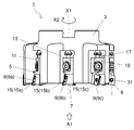
図1に示す切削工具1は、ホルダ3と、第1固定部材5と、第2固定部材7と、複数のインサート9とを備えている。なお、本実施形態の切削工具1は、8つのインサート9を備えているが、インサート9の数は8つに限定されるものではない。切削工具1が複数のインサート9を備えていればよいことから、インサート9の数は、2つ〜7つであっても、9つ以上であってもよい。
The
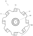
ホルダ3は、図3に示すように、回転軸X1を有しており、この回転軸X1に沿って第1端から第2端にかけて延びる柱状体である。被削加工物を製造するための被削材の切削加工時において、ホルダ3は回転軸X1を中心に回転軸X1の周りで回転方向X2に回転する。図3に示す例においてホルダ3は円柱状体であり、この円柱状体の一部が切り欠かれた第1ポケット11、第2ポケット13を有している。本実施形態においては、柱状体であるホルダ3の中心軸と、ホルダ3の回転軸X1とが一致している。
As shown in FIG. 3, the
以下、第1端を先端というとともに第2端を後端という。また、回転軸X1に近い側を内側といい、回転軸X1から遠い側を外周側という。また、ホルダ3の後端から先端に向かう方向を先端方向といい、ホルダ3の先端から後端に向かう方向を後端方向という。
Hereinafter, the first end is referred to as a tip and the second end is referred to as a rear end. The side closer to the rotation axis X1 is referred to as the inner side, and the side far from the rotation axis X1 is referred to as the outer peripheral side. Further, the direction from the rear end to the tip of the
本実施形態におけるホルダ3は、図3及び図4に示すように、第1ポケット11及び第2ポケット13を有している。第1ポケット11及び第2ポケット13は、それぞれホルダ3における先端側に位置している。第2ポケット13は、第1ポケット11に対して回転軸X1の周りでの回転方向X2の後方に位置している。第1ポケット11及び第2ポケット13は、ホルダ3を構成する柱状体における先端側を部分的に切り欠いたような形状となっており、先端側及び外周側に開口する凹形状となっている。
The
図1及び2に示すように、第1ポケット11には第1固定部材5が、第2ポケット13には第2固定部材7が、それぞれ位置している。本実施形態における第1固定部材5は、第1ポケット11にネジ止め固定されている。第2固定部材7は、第2ポケット13に第1固定部材5と同様にネジ止め固定されている。第1固定部材5及び第2固定部材7は、それぞれインサート9をホルダ3に固定するために用いられる部材である。
As shown in FIGS. 1 and 2, the
本実施形態では、切削工具1が8つのインサート9を備えていることから、ホルダ3は第1ポケット11及び第2ポケット13に加えて第3〜第8ポケットを備えている。また、第3〜第8ポケットには、それぞれ第3〜第8固定部材が位置している。第1〜第8ポケットは、回転軸X1の周りでの回転方向X2の逆周りで順に並んでいる。従って、第1〜第8固定部材もまた、回転軸X1の周りでの回転方向X2の逆周りで順に並んでいる。
In the present embodiment, since the
図5及び図6に示す第1固定部材5、図7に示す第2固定部材7は、それぞれ概ね四角
柱状体であり、先端側にあたる図示における左側に凹部15を有している。凹部15は、インサート9が取り付けられる領域であり、先端側及び外周側にそれぞれ開口している。以下、第1固定部材5における凹部15を第1凹部15a、第2固定部材7における凹部15を第2凹部15bとする。また、第1凹部15aに位置するインサート9を第1インサート9a、第2凹部15bに位置するインサート9を第2インサート9bとする。
The
第1固定部材5及び第2固定部材7は、同一形状ではなく、第1凹部15a及び第2凹部15bの位置が異なっている。具体的には、第1ポケット11に位置している状態での第1固定部材5における第1凹部15aの軸方向の位置が、第2ポケット13に位置している状態での第2固定部材7における第2凹部15bの軸方向の位置と異なっている。
The
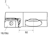
例えば、図5に示すように、第1ポケット11内に第1固定部材5をネジ止め固定するための孔から第1凹部15aまでの軸方向の長さをδ1、図7に示すように、第2ポケット13内に第2固定部材7をネジ止め固定するための孔から第2凹部15bまでの軸方向の長さをδ2としたとき、δ2がδ1よりも大きな値となっている。
For example, as shown in FIG. 5, the axial length from the hole for screwing and fixing the
本実施形態においては、第2凹部15bが第1凹部15aよりも先端側に位置している。そのため、回転方向X2の前後に位置する2つのインサート9(第1インサート9a及び第2インサート9b)における軸方向の突出量は変わることとなる。
In the present embodiment, the
このように、ポケット内に固定部材をネジ止め固定するための孔から凹部までの軸方向の長さの異なる固定部材を用いることにより、煩雑な作業を伴うことなく、容易にインサート9の軸方向の突出量を調整することができる。
In this way, by using fixing members having different axial lengths from the holes for screwing and fixing the fixing member in the pocket to the recesses, the
なお、図8において、第1インサート9a及び第2インサート9bを含む複数のインサートを仮想的に並べて、複数のインサート9の回転軸に沿った方向での位置関係を示すことによって、これら複数のインサートにおける軸方向の相対的な突出量を図示している。図8においては、左側が先端側であり、右側が後端側となっている。
In FIG. 8, a plurality of inserts including the
本実施形態の切削工具1においては、回転方向の前後に位置する2つのインサート9における突出量の差が、図8に示すように、それぞれΔに設定されている。このように突出量の差を一定の値とすることで複数のインサート9に加わる切削負荷のばらつきを小さくできる。
In the
本実施形態の切削工具1では、ポケット内に固定部材をネジ止め固定するための孔から凹部までの軸方向の長さの異なる固定部材を用いて、第2凹部15bが第1凹部15aよりも先端側に位置させることによって、回転方向X2の前後に位置する2つのインサート9における軸方向の突出量を調整することが可能となっているが、第2凹部15bが第1凹部15aよりも外周側に位置していることによって、回転方向X2の前後に位置する2つのインサート9における軸方向に直交する方向、すなわち径方向での突出量を調整することも可能である。
In the
例えば、第2凹部15bが、第1凹部15aよりも先端側に位置しているとともに、第1凹部15aが、第2凹部15bよりも外周側に位置している場合には、被削材の切削加工時において第1インサート9aに加わる切削抵抗と第2インサート9bに加わる切削抵抗とのばらつきを小さくすることができる。
For example, when the
既に示した通り、本実施形態におけるホルダ3は、第1ポケット11及び第2ポケット13に加えてこれらのポケットに対して回転方向X2の後方に位置する第3ポケット17を備えており、第3ポケット17には、第3固定部材19が位置している。第3固定部材
19は、第2固定部材7における第2凹部15bと同様に、第3凹部15cを有している。
As already shown, the
このとき、第3凹部15cが、第2凹部15bよりも先端側に位置している。そのため、第1インサート9a及び第2インサート9bだけでなく、第3凹部15cに位置する第3インサート9cを加えた複数のインサート9において軸方向の突出量を調整することが可能となる。
At this time, the
第1〜第3ポケット11,13,17を含む複数のポケットは、回転軸X1の周りに回転対称となるように等間隔で設けられていても不等間隔で設けられていてもよい。各ポケットに取り付けられるインサート9に加わる切削負荷のばらつきを抑えるためには、複数のポケットは、等間隔、すなわち互いに隣り合うポケットの間隔が一定であることが有効である。
The plurality of pockets including the first to
一方、切削工具1のびびり振動を抑えるためには、互いに隣り合うポケットの間隔を一定としないことが有効である。例えば、本実施形態においては、先端側からの端面視において、第1ポケット11に位置する第1凹部15aと第2ポケット13に位置する第2凹部15bとの間隔が、この第2凹部15bと第3ポケット17に位置する第3凹部15cとの間隔と若干異なっている。
On the other hand, in order to suppress the chatter vibration of the
第1ポケット11及び第2ポケット13を含む複数のポケットが、回転軸X1の周りで回転させた際に互いに重なり合って一致する形状となっている、すなわち、第1ポケット11及び第2ポケット13を含む複数のポケットが回転軸X1の周りで回転対称となっている場合には、各インサート9の軸方向の突出量を所定の値に容易に設定できる。
A plurality of pockets including the
これは、例えば、第1固定部材5を第2ポケット13に誤装着した場合のように、仮に第1固定部材5及び第2固定部材7を含む複数の固定部材を誤ったポケットに装着した場合であっても、インサート9の軸方向の突出量が変わってしまうことが避けられるからである。
This is the case where a plurality of fixing members including the first fixing
ホルダ3の材質としては、鋳鉄、アルミ合金及び強度の高い鋼が一例として挙げられる。ホルダ3の大きさは、被削材の大きさに応じて適宜設定される。例えば、回転軸X1に沿った方向の長さは、30〜90mm程度に設定される。また、回転軸X1に直交する方向の幅(直径)は、20〜500mm程度に設定される。第1固定部材5及び第2固定部材7を含む複数の固定部材の材質としては、ホルダ3と同様に、鋳鉄、アルミ合金及び鋼が一例として挙げられる。
Examples of the material of the
本実施形態におけるインサート9は、図9に示すように、切刃21を有する板状体である。具体的には、四角形状の上面23と、四角形状の下面25と、上面23及び下面25の間に位置する側面27とを具備した四角板状体である。なお、図9においては、複数のインサート9の一例として、第1インサート9aを図示している。
As shown in FIG. 9, the
インサート9をホルダ3に取り付けた際には、上面23が回転方向X2の前方に位置し、下面25が回転方向X2の後方に位置する。側面27は、四角形状の上面23及び下面25の各辺部に対応して4つの面領域によって構成されている。
When the
インサート9は、上面23と側面27とが交わる部分の少なくとも一部に位置する切刃21を有している。本実施形態におけるインサート9では、上面23と側面27とが交わる部分のほぼ全体に切刃21が位置している。
The
インサート9をホルダ3に装着した状態において、切刃21の一部は、ホルダ3の先端よりも突出するように位置しており、また、切刃21の別の一部は、ホルダ3の外周よりも突出するように位置している。切刃21におけるホルダ3の先端よりも突出するように位置している部分を、いわゆる底刃として機能させることが可能である。また、切刃21におけるホルダ3の外周よりも突出するように位置している部分を、いわゆる外周刃として機能させることが可能である。
When the
本実施形態の切削工具1は、ホルダ3が回転軸X1の周りで回転しつつ、回転軸X1に概ね直交する方向に移動することによって被削材を切削する、いわゆるフライス加工に用いることが可能である。そのため、被削材を主に切削する「主切刃」として外周刃を機能させるとともに、被削材の加工面の凹凸を少なくする「さらい刃」として底刃を機能させてもよい。
The
上面23が回転方向X2の前方に位置しており、切刃21が上面23の外周縁に位置していることから、上面23を、切削加工を行う際に切屑が流れる「すくい面」として機能させることが可能である。また、側面27を、切削加工を行う際に「逃げ面」として機能させることが可能である。
Since the
インサート9の材質としては、例えば、超硬合金あるいはサーメットなどが挙げられる。超硬合金の組成としては、例えば、WC−Co、WC−TiC−CoおよびWC−TiC−TaC−Coが挙げられる。ここで、WC(炭化タングステン)、TiC(炭化チタン)、TaC(炭化タンタル)は硬質粒子であり、Co(コバルト)は結合相である。
Examples of the material of the
また、サーメットは、セラミック成分に金属を複合させた焼結複合材料である。具体的には、サーメットとして、TiCまたはTiN(窒化チタン)を主成分としたチタン化合物が挙げられる。 Cermet is a sintered composite material in which a metal is composited with a ceramic component. Specifically, examples of the cermet include a titanium compound containing TiC or TiN (titanium nitride) as a main component.
インサート9の表面は、化学蒸着(CVD)法または物理蒸着(PVD)法を用いて被膜でコーティングされていてもよい。被膜の組成としては、TiC、TiN、TiCN(炭窒化チタン)およびAl2O3(アルミナ)などが挙げられる。また、切刃21部分の強度を高めるために、インサート9は、上記の材質によって構成された基体に、例えばダイヤモンド焼結体又はcBN焼結体をロウ付けした構成であってもよい。
The surface of the
インサート9は、互いに反対側に位置する面において開口する貫通孔(不図示)を有している。本実施形態における貫通孔は、下面25と交差しており、下面25から上面23にかけて位置している。そのため、本実施形態において、貫通孔は側面27に開口していない。ただし、貫通孔の構成としてはこれに限定されず、側面27における互いに反対側に位置する領域のそれぞれに開口する構成であってもよい。
The
貫通孔は、インサート9を第1固定部材5及び第2固定部材7を含む複数の固定部材にそれぞれネジ止めするための部位である。すなわち、インサート9の貫通孔にネジ31を挿通し、このネジ31の先端を固定部材に形成されたネジ孔(不図示)に挿入して、ネジ31をネジ孔に固定させることによって、インサート9が固定部材に固定される。例えば、第1インサート9aは、第1固定部材5に固定され、第2インサート9bは、第2固定部材7に固定される。
The through hole is a portion for screwing the
第1インサート9a及び第2インサート9bを含む複数のインサート9は、互いに異なる形状であってもよく、また、同じ形状であってもよい。複数のインサート9が同じ形状である場合には、例えば、第1インサート9aを第2固定部材7に誤装着した場合のように、仮に第1インサート9a及び第2インサート9bを含む複数のインサート9を誤った
固定部材に装着した場合であっても、インサート9の軸方向の突出量が変わってしまうことが避けられる。また、複数のインサート9が同じ形状である場合には、異なる種類のインサート9を準備する必要がないため、在庫管理の面でもメリットがある。
The plurality of
インサート9の大きさは特に限定されるものではないが、例えば、上面23の1辺の長さが5〜20mm程度に設定される。また、貫通孔の中心軸に沿った方向での上面23から下面25までの厚みの最大値は2〜10mmである。
The size of the
複数のインサート9は、第1固定部材5及び第2固定部材7を含む複数の固定部材に対してそれぞれ交換可能である。そのため、被削材の切削加工を行っている際に摩耗或いは破損した場合には、新しいインサート9と取り換えることができる。
The plurality of
以上、一実施形態の切削工具1について図面を用いて詳細に説明したが、本発明の切削工具は上記の実施形態の構成に限定されるものではない。
Although the
次に、一実施形態の切削加工物の製造方法について図面を用いて説明する。 Next, a method for manufacturing a machined product according to an embodiment will be described with reference to the drawings.
切削加工物は、被削材101を切削加工することによって作製される。本実施形態における切削加工物の製造方法は、以下の工程を備えている。すなわち、
(1)上記実施形態に代表される切削工具1を回転軸X1の周りで回転させる工程と、
(2)回転している切削工具1を被削材101に接触させる工程と、
(3)切削工具1を被削材101から離す工程と、
を備えている。
The work piece is produced by cutting the
(1) A step of rotating the
(2) A process of bringing the
(3) The process of separating the
Is equipped with.
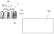
より具体的には、まず、図10に示すように、切削工具1を回転軸X1の周りで回転させるとともにY1方向に移動させることによって、切削工具1を被削材101に相対的に近付ける。次に、図11に示すように、切削工具1における切刃21を被削材101に接触させて、被削材101を切削する。そして、図12に示すように、切削工具1をY2方向に移動させることによって、切削工具1を被削材101から相対的に遠ざける。
More specifically, first, as shown in FIG. 10, the
本実施形態においては、被削材101を固定するとともに回転軸X1の周りで切削工具1を回転させた状態で被削材101に近づけている。また、図11においては、回転しているインサートの切刃21を被削材101に接触させることによって被削材101を切削している。また、図12においては、切削工具1を回転させた状態で被削材101から遠ざけている。
In the present embodiment, the
なお、本実施形態の製造方法における切削加工では、それぞれの工程において、切削工具1を動かすことによって、切削工具1を被削材101に接触させる、或いは、切削工具1を被削材101から離しているが、当然ながらこのような形態に限定されるものではない。
In the cutting process in the manufacturing method of the present embodiment, the
例えば、(1)の工程において、被削材101を切削工具1に近づけてもよい。同様に、(3)の工程において、被削材101を切削工具1から遠ざけてもよい。切削加工を継続する場合には、切削工具1を回転させた状態を維持して、被削材101の異なる箇所にインサートにおける切刃21を接触させる工程を繰り返せばよい。
For example, in the step (1), the
なお、被削材101の材質の代表例としては、アルミ、炭素鋼、合金鋼、ステンレス、鋳鉄、又は非鉄金属などが挙げられる。
Typical examples of the material of the
1・・・切削工具
3・・・ホルダ
5・・・第1固定部材
7・・・第2固定部材
9・・・インサート
9a・・・第1インサート
9b・・・第2インサート
X1・・・回転軸
X2・・・回転方向
11・・・第1ポケット
13・・・第2ポケット
15・・・凹部
15a・・・第1凹部
15b・・・第2凹部
15c・・・第3凹部
17・・・第3ポケット
19・・・第3固定部材
21・・・切刃
23・・・上面
25・・・下面
27・・・側面
31・・・ネジ
101・・・被削材
1 ... Cutting
Claims (6)
前記第1ポケットに位置し、前記第1ポケット内に固定するための第1孔と前記第1端の側に位置する第1凹部とを有する第1固定部材と、
前記第2ポケットに位置し、前記第2ポケット内に固定するための第2孔と前記第1端の側に位置する第2凹部とを有する第2固定部材と、
前記第1凹部及び前記第2凹部にそれぞれ位置する複数のインサートとを備え、
前記第2孔から前記第2凹部までの前記回転軸方向の長さは、前記第1孔から前記第1凹部までの前記回転軸方向の長さよりも長く、
前記第2凹部が、前記第1凹部よりも前記第1端の側に位置している切削工具。 A columnar body extending from the first end to the second end along the axis of rotation with respect to the first pocket located on the side of the first end and the first pocket on the side of the first end. A holder having a second pocket located rearward in the direction of rotation around the axis of rotation.
Located in the first pocket, a first fixing member having a first recess which is located on the side of the first hole and the first end for securing to said first pocket,
Located in the second pocket, and a second fixing member having a second recess which is located on the side of the second hole and the first end for securing to said second pocket,
A plurality of inserts located in the first recess and the second recess are provided.
The length in the rotation axis direction from the second hole to the second recess is longer than the length in the rotation axis direction from the first hole to the first recess.
A cutting tool in which the second recess is located closer to the first end than the first recess.
前記第3ポケットに位置し、前記第1端の側に第3凹部を有する第3固定部材をさらに備え、
前記第3凹部が、前記第2凹部よりも前記第1端の側に位置している、請求項1又は2に記載の切削工具。 The holder further has a third pocket on the side of the first end and located rearward of the second pocket in the direction of rotation of the axis of rotation.
Further provided with a third fixing member located in the third pocket and having a third recess on the side of the first end.
The cutting tool according to claim 1 or 2, wherein the third recess is located closer to the first end than the second recess.
回転している前記切削工具を被削材に接触させる工程と、
前記切削工具を前記被削材から離す工程とを備えた切削加工物の製造方法。 The step of rotating the cutting tool according to any one of claims 1 to 5,
The process of bringing the rotating cutting tool into contact with the work material,
A method for manufacturing a work piece, which comprises a step of separating the cutting tool from the work material.
Priority Applications (1)
| Application Number | Priority Date | Filing Date | Title |
|---|---|---|---|
| JP2016166691A JP6825854B2 (en) | 2016-08-29 | 2016-08-29 | Manufacturing method of cutting tools and cutting products |
Applications Claiming Priority (1)
| Application Number | Priority Date | Filing Date | Title |
|---|---|---|---|
| JP2016166691A JP6825854B2 (en) | 2016-08-29 | 2016-08-29 | Manufacturing method of cutting tools and cutting products |
Publications (2)
| Publication Number | Publication Date |
|---|---|
| JP2018034215A JP2018034215A (en) | 2018-03-08 |
| JP6825854B2 true JP6825854B2 (en) | 2021-02-03 |
Family
ID=61565111
Family Applications (1)
| Application Number | Title | Priority Date | Filing Date |
|---|---|---|---|
| JP2016166691A Active JP6825854B2 (en) | 2016-08-29 | 2016-08-29 | Manufacturing method of cutting tools and cutting products |
Country Status (1)
| Country | Link |
|---|---|
| JP (1) | JP6825854B2 (en) |
Families Citing this family (1)
| Publication number | Priority date | Publication date | Assignee | Title |
|---|---|---|---|---|
| KR102390169B1 (en) * | 2018-03-18 | 2022-04-25 | 이화다이아몬드공업 주식회사 | Milling cutter attached wedge type blade having sequential cutting tip |
Family Cites Families (18)
| Publication number | Priority date | Publication date | Assignee | Title |
|---|---|---|---|---|
| JPS5622644B2 (en) * | 1973-09-05 | 1981-05-26 | ||
| DD116565A1 (en) * | 1974-10-08 | 1975-12-05 | ||
| US4470731A (en) * | 1981-07-08 | 1984-09-11 | General Electric Company | Milling cutter with adjustable finishing insert |
| JPS62124812A (en) * | 1985-11-25 | 1987-06-06 | Honda Motor Co Ltd | Adjusting method and device for cutting edge of milling cutter |
| JP3186341B2 (en) * | 1993-06-11 | 2001-07-11 | 三菱マテリアル株式会社 | Indexable face milling |
| SE508388C2 (en) * | 1993-09-06 | 1998-10-05 | Sandvik Ab | Milling body including inserts with angle adjustment |
| IL120762A (en) * | 1997-05-02 | 2001-04-30 | Iscar Ltd | Cutting tool and insert bearing cartridge therefor |
| DE19725219C2 (en) * | 1997-06-15 | 1999-05-20 | Walter Ag | Milling tool with axial adjustment of the insert seat |
| AU2003234244A1 (en) * | 2002-04-29 | 2003-11-17 | Kennametal Inc. | Cutting tool |
| JP2004114259A (en) * | 2002-09-27 | 2004-04-15 | Ngk Spark Plug Co Ltd | Cutter body base machine, cutter body, throw-away type rotating tool, and its clamping method |
| JP2004223630A (en) * | 2003-01-21 | 2004-08-12 | Toshiba Tungaloy Co Ltd | Front face milling cutter |
| JP4289660B2 (en) * | 2003-02-17 | 2009-07-01 | 株式会社タンガロイ | Rotating tool |
| US6942432B2 (en) * | 2003-03-28 | 2005-09-13 | Sandvik Intellectual Property Ab | Milling cutter and insert-carrying cartridge for use therein |
| JP2005342850A (en) * | 2004-06-03 | 2005-12-15 | Mitsubishi Materials Corp | Throwaway type face milling cutter and mounting member of supporter for use in face milling cutter |
| JP2007038330A (en) * | 2005-08-02 | 2007-02-15 | Kobe Steel Ltd | Cutting cartridge and cutting tool |
| JP5169579B2 (en) * | 2008-07-25 | 2013-03-27 | 株式会社デンソー | Milling cutter |
| SE535147C2 (en) * | 2009-12-18 | 2012-04-24 | Sandvik Intellectual Property | Device for milling material |
| US9597738B2 (en) * | 2011-03-22 | 2017-03-21 | Renault S.A.S. | Milling/surfacing method and device |
-
2016
- 2016-08-29 JP JP2016166691A patent/JP6825854B2/en active Active
Also Published As
| Publication number | Publication date |
|---|---|
| JP2018034215A (en) | 2018-03-08 |
Similar Documents
| Publication | Publication Date | Title |
|---|---|---|
| US10124426B2 (en) | Cutting insert, cutting tool, and method of manufacturing machined product | |
| EP3213841B1 (en) | Cutting tool, and method for producing cut object | |
| JP6861269B2 (en) | Manufacturing method for cutting inserts, cutting tools and cutting products | |
| JP6185376B2 (en) | Cutting insert, cutting tool and method of manufacturing workpiece | |
| JP7032424B2 (en) | Manufacturing method for cutting inserts, cutting tools and cutting materials | |
| EP3072618B1 (en) | Cutting insert, cutting tool and method for producing a cut article | |
| JP6825854B2 (en) | Manufacturing method of cutting tools and cutting products | |
| WO2017073663A1 (en) | Cutting tool holder, cutting tool, and method for producing cut workpiece | |
| WO2016186217A1 (en) | Holder, cutting tool, and method for manufacturing cut product using same | |
| JP7045460B2 (en) | Manufacturing method of cutting tools and cutting products | |
| JP6457632B2 (en) | CUTTING TOOL AND PROCESS FOR PRODUCING CUT WORK | |
| CN112930236B (en) | Cutting insert, cutting tool, and method for manufacturing cut product | |
| WO2016208772A1 (en) | Cutting tool and method of manufacturing cut workpiece | |
| US11370040B2 (en) | Rotary tool and method for manufacturing machined product | |
| JP6616176B2 (en) | Cutting tools | |
| JP2020172005A (en) | Machining insert, machining tool, and method for manufacturing machined workpiece | |
| WO2023228741A1 (en) | Cutting tool and method for producing cut workpiece | |
| WO2023176618A1 (en) | Cutting insert, cutting tool, and method for manufacturing cut workpiece | |
| US11969808B2 (en) | Cutting tool and method for manufacturing machined product | |
| WO2024048257A1 (en) | Cutting insert, cutting tool, and method for manufacturing cut workpiece | |
| CN112601626B (en) | Cutting tool and method for manufacturing cut product | |
| JP7223773B2 (en) | Manufacturing method for rotary tool and cut product | |
| JP7279163B2 (en) | Manufacturing method for rotary tool and cut product | |
| WO2023176619A1 (en) | Cutting insert, cutting tool, and method for manufacturing cut workpiece | |
| JP5762020B2 (en) | Cutting insert, cutting tool, and cutting method of work material using the same |
Legal Events
| Date | Code | Title | Description |
|---|---|---|---|
| A621 | Written request for application examination |
Free format text: JAPANESE INTERMEDIATE CODE: A621 Effective date: 20190322 |
|
| A131 | Notification of reasons for refusal |
Free format text: JAPANESE INTERMEDIATE CODE: A131 Effective date: 20200519 |
|
| A521 | Written amendment |
Free format text: JAPANESE INTERMEDIATE CODE: A523 Effective date: 20200701 |
|
| TRDD | Decision of grant or rejection written | ||
| A01 | Written decision to grant a patent or to grant a registration (utility model) |
Free format text: JAPANESE INTERMEDIATE CODE: A01 Effective date: 20201215 |
|
| A61 | First payment of annual fees (during grant procedure) |
Free format text: JAPANESE INTERMEDIATE CODE: A61 Effective date: 20210114 |
|
| R150 | Certificate of patent or registration of utility model |
Ref document number: 6825854 Country of ref document: JP Free format text: JAPANESE INTERMEDIATE CODE: R150 |