WO2023176618A1 - Cutting insert, cutting tool, and method for manufacturing cut workpiece - Google Patents
Cutting insert, cutting tool, and method for manufacturing cut workpiece Download PDFInfo
- Publication number
- WO2023176618A1 WO2023176618A1 PCT/JP2023/008795 JP2023008795W WO2023176618A1 WO 2023176618 A1 WO2023176618 A1 WO 2023176618A1 JP 2023008795 W JP2023008795 W JP 2023008795W WO 2023176618 A1 WO2023176618 A1 WO 2023176618A1
- Authority
- WO
- WIPO (PCT)
- Prior art keywords
- cutting
- corner
- cutting edge
- cutting insert
- curvature
- Prior art date
Links
Images


Classifications
-
- B—PERFORMING OPERATIONS; TRANSPORTING
- B23—MACHINE TOOLS; METAL-WORKING NOT OTHERWISE PROVIDED FOR
- B23C—MILLING
- B23C5/00—Milling-cutters
- B23C5/02—Milling-cutters characterised by the shape of the cutter
- B23C5/06—Face-milling cutters, i.e. having only or primarily a substantially flat cutting surface
-
- B—PERFORMING OPERATIONS; TRANSPORTING
- B23—MACHINE TOOLS; METAL-WORKING NOT OTHERWISE PROVIDED FOR
- B23C—MILLING
- B23C5/00—Milling-cutters
- B23C5/16—Milling-cutters characterised by physical features other than shape
- B23C5/20—Milling-cutters characterised by physical features other than shape with removable cutter bits or teeth or cutting inserts
Definitions
- the present disclosure relates to a cutting insert, a cutting tool, and a method for manufacturing a cut workpiece.
- An example of a cutting tool is a so-called rotary tool.
- rotary tools include end mills and milling tools.
- a cutting insert described in Patent Document 1 is known as a cutting insert used in a cutting tool.
- the cutting insert described in Patent Document 1 is a so-called double-sided insert that has cutting edges on each of the upper surface side and the lower surface side.
- the cutting edge in Patent Document 1 has a secondary cutting edge (so-called wiper edge) for finishing.
- the auxiliary cutting edge has a convex curved shape that projects upward in side view.
- Patent Document 1 exemplifies a circular arc shape with a constant curvature in side view and a convex curve shape with a curvature that gradually decreases toward both ends as specific shapes of the auxiliary cutting edge.
- the cutting insert according to the present disclosure includes an upper surface, a lower surface located on the opposite side of the upper surface, a side surface connected to the upper surface and the lower surface, an upper cutting edge located at the intersection of the upper surface and the side surface, and a lower surface and the side surface. and a lower cutting edge located at the intersection.
- the top surface has a first corner, a first side connected to the first corner, and a second side opposite the first side and connected to the first corner.
- the upper cutting edge includes a main cutting edge located on the first side and having a linear shape when viewed from above, a minor cutting edge located on the second side and having a linear shape when viewed from above, and a secondary cutting edge located at the first corner, It has a connecting blade that is connected to the main cutting edge and the secondary cutting edge and has a convex shape (convex curved shape) that projects outward in a top view.
- the auxiliary cutting edge has a convex curved shape that projects upward in a side view, and includes a first portion including the most upwardly protruding apex of the auxiliary cutting edge, and a connecting blade between the first portion and the connecting blade.
- the second portion and the third portion each approach the lower surface as they move away from the first portion.
- the radius of curvature of the second portion is larger than the radius of curvature of the first portion and the radius of curvature of the third portion.
- the cutting tool according to the present disclosure has a cylindrical shape extending from a first end to a second end along a rotation axis, and includes a holder having a pocket located on the first end side, and a main body located in the pocket.
- a cutting insert according to the disclosure is a cylindrical shape extending from a first end to a second end along a rotation axis, and includes a holder having a pocket located on the first end side, and a main body located in the pocket.
- a method for manufacturing a cut workpiece according to the present disclosure includes a step of rotating a cutting tool according to the present disclosure, a step of bringing the rotating cutting tool into contact with a workpiece, and a step of separating the cutting tool from the workpiece. Be prepared.
- FIG. 1 is a schematic perspective view of a cutting insert according to an embodiment of the present disclosure.
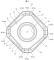
- FIG. 2 is a schematic plan view of the cutting insert shown in FIG. 1.
- FIG. 2 is a schematic side view of the cutting insert shown in FIG. 1.
- FIG. 4 is an enlarged view of section IV in FIG. 3.
- FIG. 1 is a schematic perspective view of a cutting tool according to an embodiment of the present disclosure.
- FIG. 6 is a schematic perspective view of the cutting tool shown in FIG. 5 viewed from another angle.
- FIG. 2 is a schematic diagram illustrating a method for manufacturing a cut workpiece according to an embodiment of the present disclosure.
- FIG. 2 is a schematic diagram illustrating a method for manufacturing a cut workpiece according to an embodiment of the present disclosure.
- FIG. 2 is a schematic diagram illustrating a method for manufacturing a cut workpiece according to an embodiment of the present disclosure.
- the surface accuracy of the machined surface of the workpiece can be improved.
- the insert center axis refers to a virtual axis passing through the center of the upper surface of the cutting insert and the center of the lower surface of the cutting insert.
- the term “inward direction” or “inner side” refers to a direction toward or toward the insert central axis in the cutting insert.
- the term “outward direction” or “outside” refers to a direction away from or a side away from the center axis of the cutting insert in the cutting insert.
- Orthogonality is not limited to exact orthogonality, but means to allow an error of approximately ⁇ 5 degrees.
- Parallel is not limited to exact parallel, but means to allow an error of about ⁇ 5 degrees.
- FIG. 1 is a schematic perspective view of a cutting insert 10 according to an embodiment of the present disclosure.
- FIG. 2 is a schematic plan view of the cutting insert 10 shown in FIG. 1.
- FIG. 3 is a schematic side view of the cutting insert 10 shown in FIG. 1. Note that FIG. 3 is a side view of the second side, which will be described later, viewed from the front.
- FIG. 4 is an enlarged view of section IV in FIG. 3.
- the cutting insert 10 is a component of a cutting tool used for cutting a workpiece W (see FIG. 7) made of a metal material or the like.
- Examples of the cutting process for the work material W include shoulder cutting, groove processing, R cutting, copying, and the like.
- the cutting insert 10 may have an upper surface 12 and a lower surface 14 located on the opposite side of the upper surface 12.
- the upper surface 12 and the lower surface 14 may each have a polygonal shape, for example an octagonal shape.
- the cutting insert 10 may have a polygonal plate shape, for example, an octagonal plate shape.
- the upper surface 12 and the lower surface 14 may each have a polygonal shape other than an octagonal shape, such as a triangular shape or a quadrangular shape.
- the cutting insert 10 may have a polygonal plate shape other than the octagonal plate shape, such as a triangular plate shape or a square plate shape.
- a polygonal shape is not limited to a polygonal shape in a strict sense.
- the upper surface 12 and the lower surface 14 may each have a shape that is rotationally symmetrical by a certain angle about the insert center axis CS.
- the upper surface 12 and the lower surface 14 may have a reversely symmetrical shape.
- the cutting insert 10 may have a shape that is rotationally symmetrical by a certain angle about the insert center axis CS, or may have a shape that is invertedly symmetrical between the front and back sides.
- the cutting insert 10 may have a plurality of side surfaces 16 located between the upper surface 12 and the lower surface 14. Side surface 16 may be connected to top surface 12 and bottom surface 14. The side surface 16 may function as a relief surface and may be parallel to the insert center axis CS.
- the cutting insert 10 is a so-called negative type cutting insert with a relief angle of 0 degrees.
- the cutting insert 10 may have a mounting hole 18 penetrating from the upper surface 12 to the lower surface 14.
- One opening of the attachment hole 18 may be located at the center of the upper surface 12, and the other opening of the attachment hole 18 may be located at the center of the lower surface 14.
- the center axis of the attachment hole 18 may coincide with the insert center axis CS.
- the cutting insert 10 may have an upper cutting edge 20 and a lower cutting edge 22.
- the upper cutting edge 20 may be located at the intersection of the upper surface 12 and the side surface 16.
- the lower cutting edge 22 may be located at the intersection of the lower surface 14 and the side surface 16.
- the cutting insert 10 may be a double-sided insert having an upper cutting edge 20 and a lower cutting edge 22.
- the upper cutting edge 20 may be located at the entire intersection of the upper surface 12 and the side surface 16, or may be located at a portion of the intersection.
- the lower cutting edge 22 may be located at the entire intersection of the lower surface 14 and the side surface 16, or may be located at a portion of the intersection.
- the polygonal top surface 12 may have a first corner 24 as one of the plurality of corners, and a second corner 26 as another one of the plurality of corners.
- the first corner 24 and the second corner 26 may each have a convex curved shape that projects outward in a top view.
- the top surface 12 has a first side 28 connected to the first corner 24 and a second side 30 connected to the first corner 24 on the opposite side of the first side 28. and may have.
- the second corner 26 may be connected to the second side 30 on the opposite side from the first corner 24 .
- the first side 28 may have a linear shape in a top view, or may approach the lower surface 14 as it moves away from the first corner 24 in a side view.
- the second side 30 may have a linear shape when viewed from above.
- first side 28 and the second side 30 are not limited to a linear shape, but may have a gently convex curved shape that protrudes outward, for example.
- “having a gentle convex curve shape” means that the radius of curvature is larger than the radius of curvature of the first corner 24 and the second corner 26, which are convex curve shapes.
- the upper surface 12 has a shape that is rotationally symmetrical by a certain angle about the insert center axis CS
- the upper surface 12 has a plurality of first corners 24 and a plurality of second corners 26, as shown in the example shown in FIG. It may have.
- the plurality of first corners 24 and the plurality of second corners 26 may be alternately located along the circumferential direction of the upper surface 12.
- the upper surface 12 may have a plurality of first sides 28 and a plurality of second sides 30.
- the upper surface 12 has a plurality of first corners 24, a plurality of second corners 26, a plurality of first sides 28, and a plurality of second sides 30, these are arranged so that the above-mentioned positional relationship is achieved.
- the radius of curvature which will be described later, may be evaluated by focusing on the parts extracted one by one.
- the upper surface 12 may have a land portion 32 located at its peripheral edge, and the land portion 32 may be connected to the upper cutting edge 20.
- the land portion 32 may have a function of increasing the strength of the cutting edge of the upper cutting blade 20.
- the land portion 32 may be a portion adjacent to the upper cutting edge 20 and shown as a straight line in a cross section perpendicular to the upper cutting edge 20 when viewed from above.
- the upper surface 12 may have a rake surface 34 located inside the land portion 32, and the rake surface 34 may be connected to the land portion 32.
- the rake face 34 may be inclined with respect to the land portion 32, and may approach the lower surface 14 as it moves away from the land portion 32.
- the top surface 12 may have a flat bottom surface 36 located inside the rake surface 34, and the bottom surface 36 may be connected to the rake surface 34.
- the bottom surface 36 may surround the opening of the attachment hole 18 and may be perpendicular to the insert center axis CS.
- the upper cutting edge 20 may have a main cutting edge 38 located on the first side 28.
- the main cutting edge 38 is a portion that can function as a main cutting edge in cutting the workpiece W.
- the main cutting edge 38 may be located on the entire first side 28 or may be located on a part of the first side 28.
- the main cutting edge 38 may have a linear shape when viewed from above.
- the upper cutting edge 20 may have a sub-cutting edge 40 located on the second side 30.
- the auxiliary cutting edge 40 may have a function as a wiper edge for finishing the machined surface of the workpiece W.
- the auxiliary cutting edge 40 may be located on the entire second side 30 or may be located on a part of the second side 30.
- the auxiliary cutting edge 40 may have a linear shape when viewed from above.
- the upper cutting blade 20 may have a first connecting blade (connecting blade) 42 located at the first corner 24, and the first connecting blade 42 has a main cutting blade. It may be connected to the blade 38 and the auxiliary cutting edge 40.
- the first connecting blade 42 may have a convex curved shape that protrudes outward in a top view.
- the upper cutting edge 20 may have a second connecting blade 44 located at the second corner 26, and the second connecting blade 44 may be connected to the auxiliary cutting edge 40.
- the second connecting blade 44 may have a convex curved shape that protrudes outward in a top view.
- the auxiliary cutting edge 40 may have a convex curved shape that protrudes upward in side view.
- the auxiliary cutting edge 40 includes a first portion 40a including a top portion 40t that protrudes most upwardly in the auxiliary cutting edge 40, and a second portion 40b located between the first portion 40a and the first connecting blade 42. , and a third portion 40c located between the second portion 40b and the first connecting blade 42.
- the length Lb of the second portion 40b of the auxiliary cutting edge 40 may be longer than the length La of the first portion 40a and the length Lc of the third portion 40c. good.
- the length of the third portion 40c of the auxiliary cutting edge 40 may be longer than the length of the first portion 40a.
- the second portion 40b and the third portion 40c of the auxiliary cutting edge 40 may each approach the lower surface 14 as they move away from the first portion 40a.
- the above-mentioned “length La” means the width of the first portion 40a in the direction perpendicular to the insert center axis CS when the insert 10 is viewed from the side.
- the above-mentioned “length Lb” means the width of the second portion 40b in the direction perpendicular to the insert center axis CS when the insert 10 is viewed from the side
- the above-mentioned “length Lc” means the width of the third portion 40c in the direction orthogonal to the insert center axis CS when the insert 10 is viewed from the side.
- the radius of curvature Rb of the second portion 40b of the auxiliary cutting edge 40 when viewed from the side, may be larger than the radius of curvature Ra of the first portion 40a and the radius of curvature Rc of the third portion 40c. good.
- the curvature of the second portion 40b of the auxiliary cutting edge 40 may be smaller than the curvature of the first portion 40a and the curvature of the third portion 40c.
- the radius of curvature Rc of the third portion 40c of the auxiliary cutting edge 40 may be larger than the radius of curvature Ra of the first portion 40a.
- the curvature of the third portion 40c of the sub-cutting edge 40 may be smaller than the curvature of the first portion 40a.
- the distance D1 from the top 40t of the auxiliary cutting edge 40 to the second corner 26 may be shorter than the distance D2 from the top 40t to the second portion 40b.
- the radius of curvature Ra of the first portion 40a, the radius of curvature Rb of the second portion 40b, and the radius of curvature Rc of the third portion 40c of the auxiliary cutting edge 40 are schematically illustrated.
- the boundary 12e between the second side 30 and the first corner 24 may be closer to the lower surface 14 than the boundary 12p between the second side 30 and the second corner 26.
- the first corner 24 may have a first connection region 24a connected to the second side 30, and the first connection region 24a may have a concave curve shape depressed downward in side view. good.
- the second corner 26 may have a second connection region 26a connected to the second side 30, and the second connection region 26a may have a convex curved shape projecting upward in a side view.
- the positions of the boundary 12e and the boundary 12p may be specified by viewing the cutting insert 10 from above. For example, if the first corner 24 and the second corner 26 have a convex curve shape when viewed from above and the second side 30 has a straight line shape, a virtual straight line is set along the second side 30, and this virtual straight line is set along the second side 30. The portions that are away from the straight line may be regarded as the boundary 12e and the boundary 12p. Further, in a case where the first corner 24 and the second corner 26 have a convex curve shape when viewed from above and the second side 30 has a gentle convex curve shape, a virtual arc is set along the second side 30. , the portions away from this virtual arc may be regarded as the boundary 12e and the boundary 12p.
- the lower surface 14 when the upper surface 12 and the lower surface 14 have a reversely symmetrical shape, the lower surface 14 includes the first corner 24, the second corner 26, and the first side of the upper surface 12. 28, the second side 30, the land portion 32, and the rake face 34.
- the structure of the parts corresponding to the first corner 24, second corner 26, first side 28, second side 30, land portion 32, and rake face 34 on the lower surface 14 is that the vertical positional relationship is reversed. Except for this, the configurations of the first corner 24, second corner 26, first side 28, second side 30, land portion 32, and rake surface 34 on the top surface 12 may be the same.
- the lower cutting edge 22 has the main cutting edge 38, the minor cutting edge 40, It may have portions corresponding to the first connecting blade 42 and the second connecting blade 44.
- the configuration of the parts of the lower cutting edge 22 corresponding to the main cutting edge 38, the auxiliary cutting edge 40, the first connecting blade 42, and the second connecting blade 44 is the same as that of the upper cutting edge, except that the vertical positional relationship is reversed.
- the configurations of the main cutting edge 38, the auxiliary cutting edge 40, the first connecting blade 42, and the second connecting blade 44 in No. 20 may be the same.
- Examples of the material of the cutting insert 10 include cemented carbide or cermet.
- Examples of the composition of cemented carbide include WC-Co, which is produced by adding cobalt (Co) powder to tungsten carbide (WC) and sintering it, and WC-Co, which is produced by adding titanium carbide (TiC) to WC-Co.
- TiC-Co or WC-TiC-TaC-Co, which is obtained by adding tantalum carbide (TaC) to WC-TiC-Co.
- cermet is a sintered composite material in which a metal is combined with a ceramic component, and specifically, a sintered composite material whose main component is a titanium compound such as titanium carbide (TiC) or titanium nitride (TiN). can be mentioned.
- TiC titanium carbide
- TiN titanium nitride
- the surface of cutting insert 10 may be coated with a film using chemical vapor deposition (CVD) or physical vapor deposition (PVD) methods.
- CVD chemical vapor deposition
- PVD physical vapor deposition
- the composition of the film include titanium carbide (TiC), titanium nitride (TiN), titanium carbonitride (TiCN), and alumina (Al 2 O 3 ).
- the auxiliary cutting edge 40 has a convex curved shape that projects upward in side view.
- the second portion 40b and the third portion 40c of the auxiliary cutting edge 40 approach the lower surface 14 as they move away from the first portion 40a.
- the radius of curvature Rb of the second portion 40b of the auxiliary cutting edge 40 is larger than the radius of curvature Ra of the first portion 40a and the radius of curvature Rc of the third portion 40c.
- the second part 40b which is a gently curved part, is arranged at the center of the auxiliary cutting edge 40
- the first part 40a which is a slightly steeply curved part
- the third part 40a which are slightly curved parts
- Portion 40c can be located. Therefore, even if the axial rake angle of the cutting insert 10 is set to a negative value, a wide area from the first portion 40a to the third portion 40c of the auxiliary cutting edge 40 can be used as a wiper edge.
- the surface accuracy (surface roughness) of the machined surface of the workpiece can be improved.
- the first portion 40a including the top portion 40t is a slightly steeply curved portion, the auxiliary cutting edge 40 bites into the workpiece W well, and the surface accuracy of the machined surface of the workpiece W is improved. can be improved.
- the third portion 40c located closest to the first connecting blade 42 is a slightly steep curved portion. Therefore, according to the example of the embodiment of the present disclosure, the subsequent cutting insert 10 bites into the workpiece W well during the cutting process, ensures the thickness of the chips, and prevents the occurrence of so-called peeling. can be reduced.
- the gentle portion of the auxiliary cutting edge 40 becomes longer, and the workpiece W
- the surface accuracy of the machined surface can be further improved.
- the length of the second portion 40b of the auxiliary cutting edge 40 is It can be made long enough. Thereby, according to the example of the embodiment of the present disclosure, the surface accuracy of the machined surface of the workpiece W can be further improved.
- the third portion 40c of the auxiliary cutting edge 40 When the length of the third portion 40c of the auxiliary cutting edge 40 is longer than the length of the first portion 40a, the third portion 40c, which is the next gentler portion of the auxiliary cutting edge 40 after the first portion 40a, is It can be made longer than the first portion 30a. Thereby, according to the example of the embodiment of the present disclosure, the surface accuracy of the machined surface of the workpiece W can be further improved.
- the flank surface of the side surface 16 connected to the second corner 26 is It becomes difficult to contact the machined surface of the workpiece W. Thereby, according to the example of the embodiment of the present disclosure, the durability of the cutting insert 10 can be improved.
- the workpiece When the boundary 12e between the second side 30 and the first corner 24 is closer to the lower surface 14 than the boundary 12p between the second side 30 and the second corner 26, the workpiece is It can be brought into contact with W gradually, and a sudden increase in cutting resistance can be suppressed. Thereby, according to the example of the embodiment of the present disclosure, the durability of the cutting insert 10 can be improved.
- FIG. 5 is a schematic perspective view of a cutting tool 46 according to an embodiment of the present disclosure.
- FIG. 6 is a schematic perspective view of the cutting tool 46 shown in FIG. 5 viewed from another angle.
- the cutting tool 46 is a tool that is used for cutting a workpiece W (see FIG. 7) and is rotatable around the rotation axis RS. be.
- the cutting tool 46 may include a holder 48 that is attached to the main shaft of a processing machine such as a milling machine.
- the holder 48 may have a cylindrical shape extending from the first end 48a to the second end 48b along the rotation axis RS.
- Examples of the material of the holder 48 include metals such as stainless steel, carbon steel, cast iron, and aluminum alloy.
- a plurality of pockets 50 may be located on the outer peripheral surface of the holder 48 at intervals in the circumferential direction.
- the plurality of pockets 50 may be located at equal intervals in the circumferential direction, or may be located at irregular intervals in the circumferential direction.
- the number of pockets 50 may be one.
- the cutting tool 46 may have a cutting insert 10 located in a pocket 50 of the holder 48.
- the cutting insert 10 may be located only in selected pockets 50 in the holder 48. Further, the cutting insert 10 may be fixed to the pocket 50 of the holder 48 by a fixing screw 52 inserted through the mounting hole 18.
- the cutting insert 10 may be secured to the pocket 50 of the holder 48 by a clamping member.
- the lower surface 14 may be used as a seating surface for attaching to the holder 48 (see FIG. 3).
- the upper surface 12 may be used as a seating surface (see FIG. 3).
- FIGS. 7 to 9 are schematic diagrams illustrating a method for manufacturing a cut workpiece according to an embodiment of the present disclosure.
- the method for manufacturing a cut workpiece according to the embodiment of the present disclosure is a method for manufacturing a cut workpiece M that is a cut workpiece W that has been subjected to cutting processing. , a first step, a second step, and a third step.
- the first step is a step of rotating the cutting tool 46.
- the second step is a step of bringing the rotating cutting tool 46 into contact with the workpiece W.
- the third step is a step of separating the cutting tool 46 from the workpiece W.
- Examples of the material of the work material W include aluminum alloy, stainless steel, carbon steel, alloy steel, cast iron, and non-ferrous metals.
- the cutting tool 46 is rotated in the rotational direction T and moved in the direction of the arrow FD to approach the workpiece W. Then, the cutting insert 10 of the rotating cutting tool 46 is moved in the direction of arrow FD while being brought into contact with the workpiece W. Thereby, the cutting tool 46 performs the cutting process on the workpiece W, and as in the example shown in FIG. 9, a machined surface Wf is formed on the workpiece.
- the cutting tool 46 is further moved in the direction of the arrow FD and separated from the workpiece W. Thereby, cutting of the work material W is completed, and a cut workpiece M, which is the cut material W that has been cut, can be manufactured. Since the cutting tool 46 has excellent cutting ability for the reason mentioned above, it is possible to manufacture a cut workpiece M with excellent processing accuracy.
- the cutting insert 10 of the cutting tool 46 may be repeatedly brought into contact with different parts of the workpiece W while the cutting tool 46 is being rotated.
- the cutting tool 46 is brought close to the workpiece W, but since it is sufficient that the cutting tool 46 and the workpiece W are relatively close to each other, for example, the workpiece W is brought close to the cutting tool 46. It's okay. In this regard, when separating the cutting tool 46 from the workpiece W, the same procedure is performed.
- Cutting insert 12 Top surface 12e Boundary between second side and first corner 12p Boundary between second side and second corner 14 Bottom surface 16 Side surface 18 Mounting hole 20 Upper cutting edge 22 Lower cutting edge 24 First corner 24a First connection area 26 Second corner 26a Second connection area 28 First side 30 Second side 32 Land part 34 Rake face 36 Bottom face 38 Main cutting edge 40 Minor cutting edge 40a First part 40b Second part 40c Third part 40t Top part 42 First Connecting blade 44 Second connecting blade 46 Cutting tool 50 Pocket 52 Fixing screw CS Insert center axis RS Rotating axis
Abstract
A minor cutting edge of a cutting insert according to an embodiment has a convex curved shape that protrudes upward in a side view, and comprises: a first part including a top portion of the minor cutting edge that protrudes farthest upward; a second part positioned between the first part and a connecting blade; and a third part positioned between the second part and the connecting blade. The second part and the third part each approach a lower surface with increasing distance from the first part. In a side view, a radius of curvature of the second part is greater than a radius of curvature of the first part and a radius of curvature of the third part.
Description
本開示は、切削インサート、切削工具、及び切削加工物の製造方法に関する。
The present disclosure relates to a cutting insert, a cutting tool, and a method for manufacturing a cut workpiece.
切削工具の一例として、所謂回転工具が挙げられる。回転工具として、エンドミル及びフライス工具などが挙げられる。
An example of a cutting tool is a so-called rotary tool. Examples of rotary tools include end mills and milling tools.
切削工具に用いられる切削インサートとして、特許文献1に記載の切削インサートが知られている。特許文献1に記載の切削インサートは、上面側及び下面側にそれぞれ切刃を有する、所謂両面インサートである。特許文献1における切刃は、仕上げ加工用の副切刃(所謂さらい刃)を有する。副切刃は、側面視において上方向に向かって突出した凸曲線形状である。特許文献1には、副切刃の具体的な形状として、側面視において、曲率を一定にした円弧形状、及び、両端に向かって曲率が次第に小さくなる凸曲線形状が例示されている。
A cutting insert described in Patent Document 1 is known as a cutting insert used in a cutting tool. The cutting insert described in Patent Document 1 is a so-called double-sided insert that has cutting edges on each of the upper surface side and the lower surface side. The cutting edge in Patent Document 1 has a secondary cutting edge (so-called wiper edge) for finishing. The auxiliary cutting edge has a convex curved shape that projects upward in side view. Patent Document 1 exemplifies a circular arc shape with a constant curvature in side view and a convex curve shape with a curvature that gradually decreases toward both ends as specific shapes of the auxiliary cutting edge.
本開示に係る切削インサートは、上面と、上面の反対側に位置する下面と、上面及び下面に接続された側面と、上面と側面との交わりに位置する上切刃と、下面と側面との交わりに位置する下切刃と、を有する。上面は、第1コーナと、第1コーナに接続された第1辺と、第1辺と反対側において第1コーナと接続された第2辺と、を有する。上切刃は、第1辺に位置し、上面視において直線形状である主切刃と、第2辺に位置し、上面視において直線形状である副切刃と、第1コーナに位置し、主切刃及び副切刃に接続され、上面視において外方に向かって突出する凸形状(凸曲線形状)である接続刃と、を有する。副切刃は、側面視において上方向に向かって突出する凸曲線形状であって、副切刃における最も上方向に向かって突出した頂部を含む第1部分と、第1部分と接続刃との間に位置する第2部分と、第2部分と接続刃との間に位置する第3部分と、を有する。第2部分及び第3部分は、それぞれ、第1部分から離れるにしたがって下面に近づくようになっている。側面視において、第2部分の曲率半径は、第1部分の曲率半径及び第3部分の曲率半径よりも大きい。
The cutting insert according to the present disclosure includes an upper surface, a lower surface located on the opposite side of the upper surface, a side surface connected to the upper surface and the lower surface, an upper cutting edge located at the intersection of the upper surface and the side surface, and a lower surface and the side surface. and a lower cutting edge located at the intersection. The top surface has a first corner, a first side connected to the first corner, and a second side opposite the first side and connected to the first corner. The upper cutting edge includes a main cutting edge located on the first side and having a linear shape when viewed from above, a minor cutting edge located on the second side and having a linear shape when viewed from above, and a secondary cutting edge located at the first corner, It has a connecting blade that is connected to the main cutting edge and the secondary cutting edge and has a convex shape (convex curved shape) that projects outward in a top view. The auxiliary cutting edge has a convex curved shape that projects upward in a side view, and includes a first portion including the most upwardly protruding apex of the auxiliary cutting edge, and a connecting blade between the first portion and the connecting blade. It has a second part located in between, and a third part located between the second part and the connecting blade. The second portion and the third portion each approach the lower surface as they move away from the first portion. In side view, the radius of curvature of the second portion is larger than the radius of curvature of the first portion and the radius of curvature of the third portion.
本開示に係る切削工具は、回転軸に沿って第1端から第2端にかけて延びた円柱形状であって、第1端の側に位置するポケットを有するホルダと、ポケット内に位置する、本開示に係る切削インサートと、を有する。
The cutting tool according to the present disclosure has a cylindrical shape extending from a first end to a second end along a rotation axis, and includes a holder having a pocket located on the first end side, and a main body located in the pocket. A cutting insert according to the disclosure.
本開示に係る切削加工物の製造方法は、本開示に係る切削工具を回転させる工程と、回転する切削工具を被削材に接触させる工程と、切削工具を被削材から離す工程と、を備える。
A method for manufacturing a cut workpiece according to the present disclosure includes a step of rotating a cutting tool according to the present disclosure, a step of bringing the rotating cutting tool into contact with a workpiece, and a step of separating the cutting tool from the workpiece. Be prepared.
特許文献1に記載の切削インサートのような両面インサートを切削工具のホルダに取付ける場合には、切削インサートのアキシャルレーキを負の値に設定する必要がある。そのため、副切刃が特許文献1に例示された形状である場合には、副切刃のうち、さらい刃として使用可能な領域が限られ、被削材の仕上げ加工が十分になされないことがある。そのため、被削材の加工面の面精度(表面粗さ)の向上が望まれている。
When attaching a double-sided insert such as the cutting insert described in Patent Document 1 to a holder of a cutting tool, it is necessary to set the axial rake of the cutting insert to a negative value. Therefore, when the minor cutting edge has the shape exemplified in Patent Document 1, the area of the minor cutting edge that can be used as a wiper edge is limited, and the work material may not be sufficiently finished. be. Therefore, it is desired to improve the surface accuracy (surface roughness) of the machined surface of the workpiece.
本開示によれば、被削材の加工面の面精度を向上させることができる。
According to the present disclosure, the surface accuracy of the machined surface of the workpiece can be improved.
以下、本開示の実施形態に係る切削インサート、切削工具、及び切削加工物の製造方法について、図面を用いて詳細に説明する。但し、以下で参照する各図は、説明の便宜上、実施形態を説明する上で必要な構成要素のみを簡略化して示したものである。従って、本開示の実施形態に係る切削インサート及び切削工具は、参照する各図に示されていない任意の構成要素を備え得る。また、各図中の構成要素の寸法は、実際の構成要素の寸法および各部材の寸法比率等を忠実に表したものではない。
Hereinafter, a cutting insert, a cutting tool, and a method for manufacturing a cut workpiece according to an embodiment of the present disclosure will be described in detail using the drawings. However, for convenience of explanation, each figure referred to below shows only constituent elements necessary for explaining the embodiment in a simplified manner. Therefore, cutting inserts and cutting tools according to embodiments of the present disclosure may include any components not shown in the referenced figures. Furthermore, the dimensions of the components in each figure do not faithfully represent the actual dimensions of the components and the dimensional ratios of each member.
本開示において、インサート中心軸とは、切削インサートにおける上面の中心及び切削インサートにおける下面の中心を通る仮想の軸のことをいう。内方向又は内側とは、切削インサートにおいてインサート中心軸に近づく方向又は近づく側のことをいう。外方向又は外側とは、切削インサートにおいてインサート中心軸から離れる方向又は離れる側のことをいう。直交とは、厳密な直交に限るものでなく、±5度程度の誤差を許容する意である。平行とは、厳密な平行に限るものでなく、±5度程度の誤差を許容する意である。
In the present disclosure, the insert center axis refers to a virtual axis passing through the center of the upper surface of the cutting insert and the center of the lower surface of the cutting insert. The term "inward direction" or "inner side" refers to a direction toward or toward the insert central axis in the cutting insert. The term "outward direction" or "outside" refers to a direction away from or a side away from the center axis of the cutting insert in the cutting insert. Orthogonality is not limited to exact orthogonality, but means to allow an error of approximately ±5 degrees. Parallel is not limited to exact parallel, but means to allow an error of about ±5 degrees.
<切削インサート>
図1から図4を参照して、本開示の実施形態に係る切削インサート10について説明する。図1は、本開示の実施形態に係る切削インサート10の模式的な斜視図である。図2は、図1に示す切削インサート10の模式的な平面図である。図3は、図1に示す切削インサート10の模式的な側面図である。なお、図3は、後述する第2辺を正面視する方向からの側面図である。図4は、図3におけるIV部の拡大図である。 <Cutting insert>
A cutting insert 10 according to an embodiment of the present disclosure will be described with reference to FIGS. 1 to 4. FIG. 1 is a schematic perspective view of acutting insert 10 according to an embodiment of the present disclosure. FIG. 2 is a schematic plan view of the cutting insert 10 shown in FIG. 1. FIG. 3 is a schematic side view of the cutting insert 10 shown in FIG. 1. Note that FIG. 3 is a side view of the second side, which will be described later, viewed from the front. FIG. 4 is an enlarged view of section IV in FIG. 3.
図1から図4を参照して、本開示の実施形態に係る切削インサート10について説明する。図1は、本開示の実施形態に係る切削インサート10の模式的な斜視図である。図2は、図1に示す切削インサート10の模式的な平面図である。図3は、図1に示す切削インサート10の模式的な側面図である。なお、図3は、後述する第2辺を正面視する方向からの側面図である。図4は、図3におけるIV部の拡大図である。 <Cutting insert>
A cutting insert 10 according to an embodiment of the present disclosure will be described with reference to FIGS. 1 to 4. FIG. 1 is a schematic perspective view of a
本開示の実施形態に係る切削インサート10は、金属材料等からなる被削材W(図7参照)の切削加工に用いられる切削工具の部品である。被削材Wの切削加工としては、例えば、肩削り加工、溝加工、R削り加工及び倣い加工等が挙げられる。
The cutting insert 10 according to the embodiment of the present disclosure is a component of a cutting tool used for cutting a workpiece W (see FIG. 7) made of a metal material or the like. Examples of the cutting process for the work material W include shoulder cutting, groove processing, R cutting, copying, and the like.
図1から図3に示す例のように、切削インサート10は、上面12と、上面12の反対側に位置する下面14と、を有してもよい。上面12及び下面14は、それぞれ、多角形状、例えば、八角形状であってもよい。換言すれば、切削インサート10は、多角板形状、例えば、八角板形状であってもよい。上面12及び下面14は、それぞれ、例えば、三角形状又は四角形状等の八角形状以外の多角形状であってもよい。換言すれば、切削インサート10は、例えば、三角板形状又は四角板形状等の八角板形状以外の多角板形状であってもよい。多角形状とは、厳密な意味での多角形の形状には限られない。
As in the example shown in FIGS. 1 to 3, the cutting insert 10 may have an upper surface 12 and a lower surface 14 located on the opposite side of the upper surface 12. The upper surface 12 and the lower surface 14 may each have a polygonal shape, for example an octagonal shape. In other words, the cutting insert 10 may have a polygonal plate shape, for example, an octagonal plate shape. The upper surface 12 and the lower surface 14 may each have a polygonal shape other than an octagonal shape, such as a triangular shape or a quadrangular shape. In other words, the cutting insert 10 may have a polygonal plate shape other than the octagonal plate shape, such as a triangular plate shape or a square plate shape. A polygonal shape is not limited to a polygonal shape in a strict sense.
図2に示す例のように、上面12及び下面14は、それぞれ、インサート中心軸CSを中心として一定角度ずつ回転対称形状であってもよい。上面12と下面14は、表裏の反転対称な形状であってもよい。換言すれば、切削インサート10は、インサート中心軸CSを中心として一定角度ずつ回転対称な形状であってもよく、表裏の反転対称な形状であってもよい。
As in the example shown in FIG. 2, the upper surface 12 and the lower surface 14 may each have a shape that is rotationally symmetrical by a certain angle about the insert center axis CS. The upper surface 12 and the lower surface 14 may have a reversely symmetrical shape. In other words, the cutting insert 10 may have a shape that is rotationally symmetrical by a certain angle about the insert center axis CS, or may have a shape that is invertedly symmetrical between the front and back sides.
図1及び図3に示す例のように、切削インサート10は、上面12と下面14との間に位置する複数の側面16を有してもよい。側面16は、上面12及び下面14に接続されてもよい。側面16は、逃げ面としての機能を有してもよく、インサート中心軸CSに対して平行であってもよい。切削インサート10は、逃げ角が0度である、いわゆるネガティブタイプの切削インサートである。
As in the example shown in FIGS. 1 and 3, the cutting insert 10 may have a plurality of side surfaces 16 located between the upper surface 12 and the lower surface 14. Side surface 16 may be connected to top surface 12 and bottom surface 14. The side surface 16 may function as a relief surface and may be parallel to the insert center axis CS. The cutting insert 10 is a so-called negative type cutting insert with a relief angle of 0 degrees.
図1から図3に示す例のように、切削インサート10は、上面12から下面14にかけて貫通した取付孔18を有してもよい。取付孔18の一方の開口部は、上面12の中央部に位置してもよく、取付孔18の他方の開口部は、下面14の中央部に位置してもよい。取付孔18の中心軸は、インサート中心軸CSと一致してもよい。
As in the examples shown in FIGS. 1 to 3, the cutting insert 10 may have a mounting hole 18 penetrating from the upper surface 12 to the lower surface 14. One opening of the attachment hole 18 may be located at the center of the upper surface 12, and the other opening of the attachment hole 18 may be located at the center of the lower surface 14. The center axis of the attachment hole 18 may coincide with the insert center axis CS.
図1及び図2に示す例のように、切削インサート10は、上切刃20と、下切刃22と、を有してもよい。上切刃20は、上面12と側面16との交わりに位置してもよい。下切刃22は、下面14と側面16との交わりに位置してもよい。換言すれば、切削インサート10は、上切刃20及び下切刃22を備えた両面インサートであってもよい。上切刃20は、上面12と側面16との交わりの全体に位置してもよく、又はその交じりの一部に位置してもよい。下切刃22は、下面14と側面16との交わりの全体に位置してもよく、又はその交じりの一部に位置してもよい。
As in the example shown in FIGS. 1 and 2, the cutting insert 10 may have an upper cutting edge 20 and a lower cutting edge 22. The upper cutting edge 20 may be located at the intersection of the upper surface 12 and the side surface 16. The lower cutting edge 22 may be located at the intersection of the lower surface 14 and the side surface 16. In other words, the cutting insert 10 may be a double-sided insert having an upper cutting edge 20 and a lower cutting edge 22. The upper cutting edge 20 may be located at the entire intersection of the upper surface 12 and the side surface 16, or may be located at a portion of the intersection. The lower cutting edge 22 may be located at the entire intersection of the lower surface 14 and the side surface 16, or may be located at a portion of the intersection.
図2に示す例のように、多角形状である上面12は、複数の角の一つとして第1コーナ24、複数の角の別の一つとして第2コーナ26を有してもよい。第1コーナ24及び第2コーナ26は、それぞれ、上面視において外方向に向かって突出する凸曲線形状であってもよい。
As in the example shown in FIG. 2, the polygonal top surface 12 may have a first corner 24 as one of the plurality of corners, and a second corner 26 as another one of the plurality of corners. The first corner 24 and the second corner 26 may each have a convex curved shape that projects outward in a top view.
図1及び図2に示す例のように、上面12は、第1コーナ24に接続された第1辺28と、第1辺28の反対側において第1コーナ24に接続された第2辺30と、を有してもよい。第2コーナ26は、第1コーナ24と反対側において第2辺30に接続されてもよい。第1辺28は、上面視において直線形状であってもよく、また、側面視において第1コーナ24から離れるにしたがって下面14に近づくようになってもよい。第2辺30は、上面視において直線形状であってもよい。
As in the example shown in FIGS. 1 and 2, the top surface 12 has a first side 28 connected to the first corner 24 and a second side 30 connected to the first corner 24 on the opposite side of the first side 28. and may have. The second corner 26 may be connected to the second side 30 on the opposite side from the first corner 24 . The first side 28 may have a linear shape in a top view, or may approach the lower surface 14 as it moves away from the first corner 24 in a side view. The second side 30 may have a linear shape when viewed from above.
上面視において、第1辺28及び第2辺30は、直線形状に限定されず、例えば、外方向に向かって突出する緩やかな凸曲線形状であってもよい。ここで、「緩やかな凸曲線形状である」とは、凸曲線形状である第1コーナ24及び第2コーナ26の曲率半径よりも大きな曲率半径であることを意味する。
In a top view, the first side 28 and the second side 30 are not limited to a linear shape, but may have a gently convex curved shape that protrudes outward, for example. Here, "having a gentle convex curve shape" means that the radius of curvature is larger than the radius of curvature of the first corner 24 and the second corner 26, which are convex curve shapes.
上面12がインサート中心軸CSを中心として一定角度ずつ回転対称となる形状である場合には、図2に示す一例のように、上面12が、複数の第1コーナ24及び複数の第2コーナ26を有してもよい。このとき、複数の第1コーナ24及び複数の第2コーナ26が、上面12の周方向に沿って交互に位置してもよい。
When the upper surface 12 has a shape that is rotationally symmetrical by a certain angle about the insert center axis CS, the upper surface 12 has a plurality of first corners 24 and a plurality of second corners 26, as shown in the example shown in FIG. It may have. At this time, the plurality of first corners 24 and the plurality of second corners 26 may be alternately located along the circumferential direction of the upper surface 12.
また、上面12が、複数の第1辺28及び複数の第2辺30を有してもよい。なお、上面12が、複数の第1コーナ24、複数の第2コーナ26、複数の第1辺28、及び複数の第2辺30を有する場合においては、上記した位置関係となるように、これらの部位から1つずつ抽出したものに焦点を当てて、後述する曲率半径の評価を行えばよい。
Furthermore, the upper surface 12 may have a plurality of first sides 28 and a plurality of second sides 30. In addition, when the upper surface 12 has a plurality of first corners 24, a plurality of second corners 26, a plurality of first sides 28, and a plurality of second sides 30, these are arranged so that the above-mentioned positional relationship is achieved. The radius of curvature, which will be described later, may be evaluated by focusing on the parts extracted one by one.
図1及び図2に示す例のように、上面12は、その周縁部に位置するランド部32を有してもよく、ランド部32は、上切刃20に接続されてもよい。ランド部32は、上切刃20の刃先強度を高める機能を有してもよい。ランド部32は、上面視した場合に上切刃20に直交する断面において、上切刃20に隣接するとともに直線で示される部分であってもよい。
As in the example shown in FIGS. 1 and 2, the upper surface 12 may have a land portion 32 located at its peripheral edge, and the land portion 32 may be connected to the upper cutting edge 20. The land portion 32 may have a function of increasing the strength of the cutting edge of the upper cutting blade 20. The land portion 32 may be a portion adjacent to the upper cutting edge 20 and shown as a straight line in a cross section perpendicular to the upper cutting edge 20 when viewed from above.
また、上面12は、ランド部32の内側に位置するすくい面34を有してもよく、すくい面34は、ランド部32に接続されてもよい。すくい面34は、ランド部32に対して傾斜しており、ランド部32から離れるにしたがって下面14に近づくようになってもよい。
Further, the upper surface 12 may have a rake surface 34 located inside the land portion 32, and the rake surface 34 may be connected to the land portion 32. The rake face 34 may be inclined with respect to the land portion 32, and may approach the lower surface 14 as it moves away from the land portion 32.
図1及び図2に示す例のように、上面12は、すくい面34の内側に位置する平坦な底面36を有してもよく、底面36は、すくい面34に接続されてもよい。底面36は、取付孔18の開口部を囲むようになっていてもよく、インサート中心軸CSに対して直交してもよい。
As in the example shown in FIGS. 1 and 2, the top surface 12 may have a flat bottom surface 36 located inside the rake surface 34, and the bottom surface 36 may be connected to the rake surface 34. The bottom surface 36 may surround the opening of the attachment hole 18 and may be perpendicular to the insert center axis CS.
図1から図3に示す例のように、上切刃20は、第1辺28に位置する主切刃38を有してもよい。主切刃38は、被削材Wの切削加工において主たる切刃として機能し得る部位である。主切刃38は、第1辺28の全体に位置してもよく、第1辺28の一部に位置してもよい。主切刃38は、上面視において直線形状であってもよい。
As in the example shown in FIGS. 1 to 3, the upper cutting edge 20 may have a main cutting edge 38 located on the first side 28. The main cutting edge 38 is a portion that can function as a main cutting edge in cutting the workpiece W. The main cutting edge 38 may be located on the entire first side 28 or may be located on a part of the first side 28. The main cutting edge 38 may have a linear shape when viewed from above.
図1から図4に示す例のように、上切刃20は、第2辺30に位置する副切刃40を有してもよい。副切刃40は、被削材Wの加工面を仕上げるためのさらい刃としての機能を有してもよい。副切刃40は、第2辺30の全体に位置してもよく、第2辺30の一部に位置してもよい。副切刃40は、上面視において直線形状であってもよい。
As in the examples shown in FIGS. 1 to 4, the upper cutting edge 20 may have a sub-cutting edge 40 located on the second side 30. The auxiliary cutting edge 40 may have a function as a wiper edge for finishing the machined surface of the workpiece W. The auxiliary cutting edge 40 may be located on the entire second side 30 or may be located on a part of the second side 30. The auxiliary cutting edge 40 may have a linear shape when viewed from above.
図1から図3に示す例のように、上切刃20は、第1コーナ24に位置する第1接続刃(接続刃)42を有してもよく、第1接続刃42は、主切刃38及び副切刃40に接続されてもよい。第1接続刃42は、上面視において外方向に向かって突出する凸曲線形状であってもよい。また、上切刃20は、第2コーナ26に位置する第2接続刃44を有してもよく、第2接続刃44は、副切刃40に接続されてもよい。第2接続刃44は、上面視において外方向に向かって突出する凸曲線形状であってもよい。
As in the example shown in FIGS. 1 to 3, the upper cutting blade 20 may have a first connecting blade (connecting blade) 42 located at the first corner 24, and the first connecting blade 42 has a main cutting blade. It may be connected to the blade 38 and the auxiliary cutting edge 40. The first connecting blade 42 may have a convex curved shape that protrudes outward in a top view. Further, the upper cutting edge 20 may have a second connecting blade 44 located at the second corner 26, and the second connecting blade 44 may be connected to the auxiliary cutting edge 40. The second connecting blade 44 may have a convex curved shape that protrudes outward in a top view.
図4に示す例のように、副切刃40は、側面視において上方向に向かって突出する凸曲線形状であってもよい。副切刃40は、副切刃40における最も上方向に向かって突出した頂部40tを含む第1部分40aと、第1部分40aと第1接続刃42との間に位置する第2部分40bと、第2部分40bと第1接続刃42との間に位置する第3部分40cと、を有してもよい。
As in the example shown in FIG. 4, the auxiliary cutting edge 40 may have a convex curved shape that protrudes upward in side view. The auxiliary cutting edge 40 includes a first portion 40a including a top portion 40t that protrudes most upwardly in the auxiliary cutting edge 40, and a second portion 40b located between the first portion 40a and the first connecting blade 42. , and a third portion 40c located between the second portion 40b and the first connecting blade 42.
図4に示す例のように、側面視において、副切刃40の第2部分40bの長さLbは、第1部分40aの長さLa及び第3部分40cの長さLcよりも長くてもよい。副切刃40の第3部分40cの長さは、第1部分40aの長さよりも長くてもよい。また、副切刃40の第2部分40b及び第3部分40cは、それぞれ、第1部分40aから離れるにしたがって下面14に近づくようになっていてもよい。
As in the example shown in FIG. 4, when viewed from the side, the length Lb of the second portion 40b of the auxiliary cutting edge 40 may be longer than the length La of the first portion 40a and the length Lc of the third portion 40c. good. The length of the third portion 40c of the auxiliary cutting edge 40 may be longer than the length of the first portion 40a. Further, the second portion 40b and the third portion 40c of the auxiliary cutting edge 40 may each approach the lower surface 14 as they move away from the first portion 40a.
なお、上記の「長さLa」とは、インサート10を側面視した場合におけるインサート中心軸CSに直交する方向での第1部分40aの幅を意味する。同様に、上記の「長さLb」とは、インサート10を側面視した場合におけるインサート中心軸CSに直交する方向での第2部分40bの幅を意味し、上記の「長さLc」とは、インサート10を側面視した場合におけるインサート中心軸CSに直交する方向での第3部分40cの幅を意味する。
Note that the above-mentioned "length La" means the width of the first portion 40a in the direction perpendicular to the insert center axis CS when the insert 10 is viewed from the side. Similarly, the above-mentioned "length Lb" means the width of the second portion 40b in the direction perpendicular to the insert center axis CS when the insert 10 is viewed from the side, and the above-mentioned "length Lc" , means the width of the third portion 40c in the direction orthogonal to the insert center axis CS when the insert 10 is viewed from the side.
図4に示す例のように、側面視において、副切刃40の第2部分40bの曲率半径Rbは、第1部分40aの曲率半径Ra及び第3部分40cの曲率半径Rcよりも大きくてもよい。言い換えれば、側面視において、副切刃40の第2部分40bの曲率は、第1部分40aの曲率及び第3部分40cの曲率よりも小さくてもよい。側面視において、副切刃40の第3部分40cの曲率半径Rcは、第1部分40aの曲率半径Raよりも大きくてもよい。言い換えれば、側面視において、副切刃40の第3部分40cの曲率は、第1部分40aの曲率よりも小さくてもよい。また、副切刃40の頂部40tから第2コーナ26までの間隔D1は、頂部40tから第2部分40bまでの間隔D2よりも短くてもよい。図4においては、副切刃40の第1部分40aの曲率半径Ra、第2部分40bの曲率半径Rb、及び第3部分40cの曲率半径Rcは、模式的に図示してある。
As in the example shown in FIG. 4, when viewed from the side, the radius of curvature Rb of the second portion 40b of the auxiliary cutting edge 40 may be larger than the radius of curvature Ra of the first portion 40a and the radius of curvature Rc of the third portion 40c. good. In other words, in a side view, the curvature of the second portion 40b of the auxiliary cutting edge 40 may be smaller than the curvature of the first portion 40a and the curvature of the third portion 40c. In a side view, the radius of curvature Rc of the third portion 40c of the auxiliary cutting edge 40 may be larger than the radius of curvature Ra of the first portion 40a. In other words, in a side view, the curvature of the third portion 40c of the sub-cutting edge 40 may be smaller than the curvature of the first portion 40a. Moreover, the distance D1 from the top 40t of the auxiliary cutting edge 40 to the second corner 26 may be shorter than the distance D2 from the top 40t to the second portion 40b. In FIG. 4, the radius of curvature Ra of the first portion 40a, the radius of curvature Rb of the second portion 40b, and the radius of curvature Rc of the third portion 40c of the auxiliary cutting edge 40 are schematically illustrated.
図4に示す例のように、第2辺30と第1コーナ24との境界12eは、第2辺30と第2コーナ26との境界12pよりも下面14に近くてもよい。また、第1コーナ24は、第2辺30に接続された第1接続領域24aを有してもよく、第1接続領域24aは、側面視において下方向に窪んだ凹曲線形状であってもよい。第2コーナ26は、第2辺30に接続された第2接続領域26aを有してもよく、第2接続領域26aは、側面視において上方向に突出した凸曲線形状であってもよい。
As in the example shown in FIG. 4, the boundary 12e between the second side 30 and the first corner 24 may be closer to the lower surface 14 than the boundary 12p between the second side 30 and the second corner 26. Further, the first corner 24 may have a first connection region 24a connected to the second side 30, and the first connection region 24a may have a concave curve shape depressed downward in side view. good. The second corner 26 may have a second connection region 26a connected to the second side 30, and the second connection region 26a may have a convex curved shape projecting upward in a side view.
境界12e及び境界12pの位置は、切削インサート10の上面視によって特定してもよい。例えば、上面視において第1コーナ24及び第2コーナ26が凸曲線形状であって、第2辺30が直線形状である場合においては、第2辺30に沿った仮想直線を設定し、この仮想直線から離れる部位を境界12e及び境界12pと見做してもよい。また、上面視において第1コーナ24及び第2コーナ26が凸曲線形状であって、第2辺30が緩やかな凸曲線形状である場合においては、第2辺30に沿った仮想円弧を設定し、この仮想円弧から離れる部位を境界12e及び境界12pと見做してもよい。
The positions of the boundary 12e and the boundary 12p may be specified by viewing the cutting insert 10 from above. For example, if the first corner 24 and the second corner 26 have a convex curve shape when viewed from above and the second side 30 has a straight line shape, a virtual straight line is set along the second side 30, and this virtual straight line is set along the second side 30. The portions that are away from the straight line may be regarded as the boundary 12e and the boundary 12p. Further, in a case where the first corner 24 and the second corner 26 have a convex curve shape when viewed from above and the second side 30 has a gentle convex curve shape, a virtual arc is set along the second side 30. , the portions away from this virtual arc may be regarded as the boundary 12e and the boundary 12p.
図1から図3に示す例のように、上面12及び下面14が表裏の反転対称な形状である場合には、下面14は、上面12における第1コーナ24、第2コーナ26、第1辺28、第2辺30、ランド部32、及びすくい面34に相当する部位を有してもよい。下面14における第1コーナ24、第2コーナ26、第1辺28、第2辺30、ランド部32、及びすくい面34に相当する部位の構成は、上下方向の位置関係を逆にした点を除き、上面12における第1コーナ24、第2コーナ26、第1辺28、第2辺30、ランド部32、及びすくい面34の構成と同じであってもよい。
As in the example shown in FIGS. 1 to 3, when the upper surface 12 and the lower surface 14 have a reversely symmetrical shape, the lower surface 14 includes the first corner 24, the second corner 26, and the first side of the upper surface 12. 28, the second side 30, the land portion 32, and the rake face 34. The structure of the parts corresponding to the first corner 24, second corner 26, first side 28, second side 30, land portion 32, and rake face 34 on the lower surface 14 is that the vertical positional relationship is reversed. Except for this, the configurations of the first corner 24, second corner 26, first side 28, second side 30, land portion 32, and rake surface 34 on the top surface 12 may be the same.
図1から図3に示す例のように、上面12及び下面14が表裏の反転対称な形状である場合には、下切刃22は、上切刃20における主切刃38、副切刃40、第1接続刃42、及び第2接続刃44に相当する部位を有してもよい。下切刃22における主切刃38、副切刃40、第1接続刃42、及び第2接続刃44に相当する部位の構成は、上下方向の位置関係を逆にした点を除き、上切刃20における主切刃38、副切刃40、第1接続刃42、及び第2接続刃44の構成と同じであってもよい。
As in the example shown in FIGS. 1 to 3, when the upper surface 12 and the lower surface 14 have a reversely symmetrical shape, the lower cutting edge 22 has the main cutting edge 38, the minor cutting edge 40, It may have portions corresponding to the first connecting blade 42 and the second connecting blade 44. The configuration of the parts of the lower cutting edge 22 corresponding to the main cutting edge 38, the auxiliary cutting edge 40, the first connecting blade 42, and the second connecting blade 44 is the same as that of the upper cutting edge, except that the vertical positional relationship is reversed. The configurations of the main cutting edge 38, the auxiliary cutting edge 40, the first connecting blade 42, and the second connecting blade 44 in No. 20 may be the same.
切削インサート10の材質としては、例えば、超硬合金又はサーメット等が挙げられる。超硬合金の組成としては、例えば、炭化タングステン(WC)にコバルト(Co)の粉末を加えて焼結して生成されるWC-Co、WC-Coに炭化チタン(TiC)を添加したWC-TiC-Co、又はWC-TiC-Coに炭化タンタル(TaC)を添加したWC-TiC-TaC-Coがある。また、サーメットは、セラミック成分に金属を複合させた焼結複合材料であり、具体的には、炭化チタン(TiC)、又は窒化チタン(TiN)等のチタン化合物を主成分とした焼結複合材料が挙げられる。
Examples of the material of the cutting insert 10 include cemented carbide or cermet. Examples of the composition of cemented carbide include WC-Co, which is produced by adding cobalt (Co) powder to tungsten carbide (WC) and sintering it, and WC-Co, which is produced by adding titanium carbide (TiC) to WC-Co. There is TiC-Co, or WC-TiC-TaC-Co, which is obtained by adding tantalum carbide (TaC) to WC-TiC-Co. In addition, cermet is a sintered composite material in which a metal is combined with a ceramic component, and specifically, a sintered composite material whose main component is a titanium compound such as titanium carbide (TiC) or titanium nitride (TiN). can be mentioned.
切削インサート10の表面は、化学蒸着(CVD)法又は物理蒸着(PVD)法を用いて被膜でコーティングされていてもよい。被膜の組成としては、炭化チタン(TiC)、窒化チタン(TiN)、炭窒化チタン(TiCN)又はアルミナ(Al2O3)などが挙げられる。
The surface of cutting insert 10 may be coated with a film using chemical vapor deposition (CVD) or physical vapor deposition (PVD) methods. Examples of the composition of the film include titanium carbide (TiC), titanium nitride (TiN), titanium carbonitride (TiCN), and alumina (Al 2 O 3 ).
図4に示す例のように、副切刃40は、側面視において上方向に向かって突出する凸曲線形状である。副切刃40の第2部分40b及び第3部分40cは、それぞれ、第1部分40aから離れるにしたがって下面14に近づくようになっている。副切刃40の第2部分40bの曲率半径Rbは、第1部分40aの曲率半径Ra及び第3部分40cの曲率半径Rcよりも大きくなっている。
As in the example shown in FIG. 4, the auxiliary cutting edge 40 has a convex curved shape that projects upward in side view. The second portion 40b and the third portion 40c of the auxiliary cutting edge 40 approach the lower surface 14 as they move away from the first portion 40a. The radius of curvature Rb of the second portion 40b of the auxiliary cutting edge 40 is larger than the radius of curvature Ra of the first portion 40a and the radius of curvature Rc of the third portion 40c.
この場合には、副切刃40の中央側に緩やかな曲線部分である第2部分40bを配置すると共に、副切刃40の両端側にやや急な曲線部分である第1部分40a及び第3部分40cを配置することができる。そのため、切削インサート10のアキシャルレーキ角を負に設定しても、副切刃40の第1部分40aから第3部分40cまでの広い領域をさらい刃として用いることができる。
In this case, the second part 40b, which is a gently curved part, is arranged at the center of the auxiliary cutting edge 40, and the first part 40a, which is a slightly steeply curved part, and the third part 40a, which are slightly curved parts, are arranged at both ends of the auxiliary cutting edge 40. Portion 40c can be located. Therefore, even if the axial rake angle of the cutting insert 10 is set to a negative value, a wide area from the first portion 40a to the third portion 40c of the auxiliary cutting edge 40 can be used as a wiper edge.
これにより、本開示の実施形態の例によれば、被削材の加工面の面精度(表面粗さ)を向上させることができる。特に、頂部40tを含む第1部分40aがやや急な曲線部分であるため、被削材Wへの副切刃40の食いつきが良好になり、被削材Wの加工面の面精度を十分に向上させることができる。
Thereby, according to the example of the embodiment of the present disclosure, the surface accuracy (surface roughness) of the machined surface of the workpiece can be improved. In particular, since the first portion 40a including the top portion 40t is a slightly steeply curved portion, the auxiliary cutting edge 40 bites into the workpiece W well, and the surface accuracy of the machined surface of the workpiece W is improved. can be improved.
また、副切刃40の第1部分40aから第3部分40cのうち、最も第1接続刃42に近くに位置する第3部分40cがやや急な曲線部分になっている。そのため、本開示の実施形態の例によれば、切削加工中に後続の切削インサート10の被削材Wへの食いつきが良好になり、切屑の肉厚を確保して、所謂むしれの発生を低減することができる。
Further, among the first portion 40a to the third portion 40c of the sub-cutting blade 40, the third portion 40c located closest to the first connecting blade 42 is a slightly steep curved portion. Therefore, according to the example of the embodiment of the present disclosure, the subsequent cutting insert 10 bites into the workpiece W well during the cutting process, ensures the thickness of the chips, and prevents the occurrence of so-called peeling. can be reduced.
副切刃40の第2部分40bの長さが第1部分40aの長さ及び第3部分40cの長さよりも長い場合には、副切刃40の緩やかな部分が長くなり、被削材Wの加工面の面精度を更に向上させることができる。
When the length of the second portion 40b of the auxiliary cutting edge 40 is longer than the length of the first portion 40a and the length of the third portion 40c, the gentle portion of the auxiliary cutting edge 40 becomes longer, and the workpiece W The surface accuracy of the machined surface can be further improved.
第1コーナ24の第1接続領域24aが凹曲線形状であり、第2コーナ26の第2接続領域26aが凸曲線形状である場合には、副切刃40の第2部分40bの長さを十分に長くすることができる。これにより、本開示の実施形態の例によれば、被削材Wの加工面の面精度を更に向上させることができる。
When the first connection area 24a of the first corner 24 has a concave curve shape and the second connection area 26a of the second corner 26 has a convex curve shape, the length of the second portion 40b of the auxiliary cutting edge 40 is It can be made long enough. Thereby, according to the example of the embodiment of the present disclosure, the surface accuracy of the machined surface of the workpiece W can be further improved.
副切刃40の第3部分40cの長さが第1部分40aの長さよりも長い場合には、副切刃40のうち、第1部分40aの次に緩やかな部分である第3部分40cを第1部分30aの次に長くすることができる。これにより、本開示の実施形態の例によれば、被削材Wの加工面の面精度を更に向上させることができる。
When the length of the third portion 40c of the auxiliary cutting edge 40 is longer than the length of the first portion 40a, the third portion 40c, which is the next gentler portion of the auxiliary cutting edge 40 after the first portion 40a, is It can be made longer than the first portion 30a. Thereby, according to the example of the embodiment of the present disclosure, the surface accuracy of the machined surface of the workpiece W can be further improved.
副切刃40の第3部分40cの曲率半径Rcが第1部分40aの曲率半径Raよりも大きい場合には、第1部分40aよりも大きな切削負荷が加わる傾向にある第3部分40cに応力集中を低減することができる。これにより、本開示の実施形態の例によれば、切削インサート10の耐久性を向上させることができる。
When the radius of curvature Rc of the third portion 40c of the auxiliary cutting edge 40 is larger than the radius of curvature Ra of the first portion 40a, stress is concentrated on the third portion 40c, which tends to receive a larger cutting load than the first portion 40a. can be reduced. Thereby, according to the example of the embodiment of the present disclosure, the durability of the cutting insert 10 can be improved.
副切刃40の頂部40tから第2コーナ26までの間隔D1が頂部40tから第2部分40bまでの間隔D2よりも短い場合には、側面16のうち第2コーナ26に接続される逃げ面が被削材Wの加工面に接触し難くなる。これにより、本開示の実施形態の例によれば、切削インサート10の耐久性を向上させることができる。
When the distance D1 from the top 40t of the auxiliary cutting edge 40 to the second corner 26 is shorter than the distance D2 from the top 40t to the second portion 40b, the flank surface of the side surface 16 connected to the second corner 26 is It becomes difficult to contact the machined surface of the workpiece W. Thereby, according to the example of the embodiment of the present disclosure, the durability of the cutting insert 10 can be improved.
第2辺30と第1コーナ24との境界12eが第2辺30と第2コーナ26との境界12pよりも下面14に近い場合には、主切刃38から副切刃40にかけて被削材Wに徐々に接触させることができ、切削抵抗の急激な上昇を抑えることができる。これにより、本開示の実施形態の例によれば、切削インサート10の耐久性を向上させることができる。
When the boundary 12e between the second side 30 and the first corner 24 is closer to the lower surface 14 than the boundary 12p between the second side 30 and the second corner 26, the workpiece is It can be brought into contact with W gradually, and a sudden increase in cutting resistance can be suppressed. Thereby, according to the example of the embodiment of the present disclosure, the durability of the cutting insert 10 can be improved.
<切削工具>
図5及び図6を参照して、本開示の実施形態に係る切削工具46について説明する。図5は、本開示の実施形態に係る切削工具46の模式的な斜視図である。図6は、図5に示す切削工具46を別の角度から見た模式的な斜視図である。 <Cutting tools>
A cuttingtool 46 according to an embodiment of the present disclosure will be described with reference to FIGS. 5 and 6. FIG. 5 is a schematic perspective view of a cutting tool 46 according to an embodiment of the present disclosure. FIG. 6 is a schematic perspective view of the cutting tool 46 shown in FIG. 5 viewed from another angle.
図5及び図6を参照して、本開示の実施形態に係る切削工具46について説明する。図5は、本開示の実施形態に係る切削工具46の模式的な斜視図である。図6は、図5に示す切削工具46を別の角度から見た模式的な斜視図である。 <Cutting tools>
A cutting
図5及び図6に示す例のように、本開示の実施形態に係る切削工具46は、被削材W(図7参照)の切削加工に用いられ、回転軸RS周りに回転可能な工具である。切削工具46は、フライス盤等の加工機の主軸に装着されるホルダ48を有してもよい。ホルダ48は、回転軸RSに沿って第1端48aから第2端48bにかけて延びた円柱形状であってもよい。ホルダ48の材質としては、例えば、ステンレス鋼、炭素鋼、鋳鉄、アルミ合金等の金属等が挙げられる。ホルダ48の外周面には、複数のポケット50が周方向に間隔を空けて位置してもよい。複数のポケット50は、周方向に等間隔に位置してもよく、又は周方向に不等間隔に位置してもよい。ポケット50の数は、1つであってもよい。
As shown in the examples shown in FIGS. 5 and 6, the cutting tool 46 according to the embodiment of the present disclosure is a tool that is used for cutting a workpiece W (see FIG. 7) and is rotatable around the rotation axis RS. be. The cutting tool 46 may include a holder 48 that is attached to the main shaft of a processing machine such as a milling machine. The holder 48 may have a cylindrical shape extending from the first end 48a to the second end 48b along the rotation axis RS. Examples of the material of the holder 48 include metals such as stainless steel, carbon steel, cast iron, and aluminum alloy. A plurality of pockets 50 may be located on the outer peripheral surface of the holder 48 at intervals in the circumferential direction. The plurality of pockets 50 may be located at equal intervals in the circumferential direction, or may be located at irregular intervals in the circumferential direction. The number of pockets 50 may be one.
図5及び図6に示す例のように、切削工具46は、ホルダ48のポケット50に位置する切削インサート10を有してもよい。切削インサート10は、ホルダ48における選択した1つ又は複数のポケット50にのみ位置してもよい。また、切削インサート10は、取付孔18に挿通させた固定ネジ52によってホルダ48のポケット50に固定されてもよい。切削インサート10は、クランプ部材によってホルダ48のポケット50に固定されてもよい。上切刃20によって切削加工を行う場合には、下面14をホルダ48に取付けるための着座面としてもよい(図3参照)。下切刃22によって切削加工を行う場合には、上面12を着座面としてもよい(図3参照)。
As in the example shown in FIGS. 5 and 6, the cutting tool 46 may have a cutting insert 10 located in a pocket 50 of the holder 48. The cutting insert 10 may be located only in selected pockets 50 in the holder 48. Further, the cutting insert 10 may be fixed to the pocket 50 of the holder 48 by a fixing screw 52 inserted through the mounting hole 18. The cutting insert 10 may be secured to the pocket 50 of the holder 48 by a clamping member. When cutting is performed using the upper cutting blade 20, the lower surface 14 may be used as a seating surface for attaching to the holder 48 (see FIG. 3). When cutting is performed using the lower cutting blade 22, the upper surface 12 may be used as a seating surface (see FIG. 3).
<切削加工物の製造方法>
図7から図9を参照して、本開示の実施形態に係る切削加工物の製造方法について説明する。図7から図9は、本開示の実施形態に係る切削加工物の製造方法を説明する模式図である。 <Method for manufacturing cut workpieces>
A method for manufacturing a cut workpiece according to an embodiment of the present disclosure will be described with reference to FIGS. 7 to 9. 7 to 9 are schematic diagrams illustrating a method for manufacturing a cut workpiece according to an embodiment of the present disclosure.
図7から図9に示す例のように、本開示の実施形態に係る切削加工物の製造方法は、切削加工済みの被削材Wである切削加工物を製造Mするための方法であって、第1工程と、第2工程と、第3工程とを備えている。第1工程とは、切削工具46を回転させる工程のことである。第2工程とは、回転している切削工具46を被削材Wに接触させる工程のことである。第3工程とは、切削工具46を被削材Wから離す工程のことである。被削材Wの材質としては、例えば、アルミ合金、ステンレス鋼、炭素鋼、合金鋼、鋳鉄、又は非鉄金属等が挙げられる。そして、本開示の実施形態に係る切削加工物の製造方法の具体的な内容は、次の通りである。
As in the examples shown in FIGS. 7 to 9, the method for manufacturing a cut workpiece according to the embodiment of the present disclosure is a method for manufacturing a cut workpiece M that is a cut workpiece W that has been subjected to cutting processing. , a first step, a second step, and a third step. The first step is a step of rotating the cutting tool 46. The second step is a step of bringing the rotating cutting tool 46 into contact with the workpiece W. The third step is a step of separating the cutting tool 46 from the workpiece W. Examples of the material of the work material W include aluminum alloy, stainless steel, carbon steel, alloy steel, cast iron, and non-ferrous metals. The specific details of the method for manufacturing a cut workpiece according to the embodiment of the present disclosure are as follows.
図7及び図8に示す例のように、切削工具46を回転方向Tに回転させつつ、矢印FD方向へ移動させて、被削材Wに近づける。そして、回転している切削工具46の切削インサート10を被削材Wに接触させながら、矢印FD方向へ移動させる。これにより、切削工具46によって被削材Wの切削加工が行われ、図9に示す例のように、被削材に加工面Wfが形成される。
As in the example shown in FIGS. 7 and 8, the cutting tool 46 is rotated in the rotational direction T and moved in the direction of the arrow FD to approach the workpiece W. Then, the cutting insert 10 of the rotating cutting tool 46 is moved in the direction of arrow FD while being brought into contact with the workpiece W. Thereby, the cutting tool 46 performs the cutting process on the workpiece W, and as in the example shown in FIG. 9, a machined surface Wf is formed on the workpiece.
その後、図9に示す例のように、切削工具46を矢印FD方向へ更に移動させて、被削材Wから離す。これにより、被削材Wの切削加工が終了し、切削加工済みの被削材Wである切削加工物Mを製造することができる。切削工具46が前述した理由から優れた切削能力を備えているので、加工精度に優れた切削加工物Mを製造することができる。
Thereafter, as in the example shown in FIG. 9, the cutting tool 46 is further moved in the direction of the arrow FD and separated from the workpiece W. Thereby, cutting of the work material W is completed, and a cut workpiece M, which is the cut material W that has been cut, can be manufactured. Since the cutting tool 46 has excellent cutting ability for the reason mentioned above, it is possible to manufacture a cut workpiece M with excellent processing accuracy.
切削加工を継続する場合には、切削工具46を回転させた状態で、被削材Wの異なる箇所への切削工具46の切削インサート10による接触を繰り返せばよい。本開示の実施形態では、切削工具46を被削材Wに近づけているが、切削工具46と被削材Wとが相対的に近づけばよいため、例えば被削材Wを切削工具46に近づけてもよい。この点、切削工具46を被削材Wから離す場合も同じように行う。
If the cutting process is to be continued, the cutting insert 10 of the cutting tool 46 may be repeatedly brought into contact with different parts of the workpiece W while the cutting tool 46 is being rotated. In the embodiment of the present disclosure, the cutting tool 46 is brought close to the workpiece W, but since it is sufficient that the cutting tool 46 and the workpiece W are relatively close to each other, for example, the workpiece W is brought close to the cutting tool 46. It's okay. In this regard, when separating the cutting tool 46 from the workpiece W, the same procedure is performed.
以上、本開示に係る発明について、諸図面および実施形態に基づいて説明してきた。しかし、本開示に係る発明は前述した実施形態に限定されるものではない。すなわち、本開示に係る発明は本開示で示した範囲で種々の変更が可能であり、開示された技術的手段を適宜組み合わせて得られる実施形態についても、本開示に係る発明の技術的範囲に含まれる。つまり、当業者であれば本開示に基づき種々の変形または修正を行うことが容易であることに注意されたい。また、これらの変形又は修正は本開示の範囲に含まれることに留意されたい。
The invention according to the present disclosure has been described above based on the drawings and embodiments. However, the invention according to the present disclosure is not limited to the embodiments described above. In other words, the invention according to the present disclosure can be modified in various ways within the scope shown in the present disclosure, and embodiments obtained by appropriately combining the disclosed technical means also fall within the technical scope of the invention according to the present disclosure. included. In other words, it should be noted that those skilled in the art can easily make various changes or modifications based on the present disclosure. It should also be noted that these variations or modifications are included within the scope of this disclosure.
10 切削インサート
12 上面
12e 第2辺と第1コーナとの境界
12p 第2辺と第2コーナとの境界
14 下面
16 側面
18 取付孔
20 上切刃
22 下切刃
24 第1コーナ
24a 第1接続領域
26 第2コーナ
26a 第2接続領域
28 第1辺
30 第2辺
32 ランド部
34 すくい面
36 底面
38 主切刃
40 副切刃
40a 第1部分
40b 第2部分
40c 第3部分
40t 頂部
42 第1接続刃
44 第2接続刃
46 切削工具
50 ポケット
52 固定ネジ
CS インサート中心軸
RS 回転軸 10Cutting insert 12 Top surface 12e Boundary between second side and first corner 12p Boundary between second side and second corner 14 Bottom surface 16 Side surface 18 Mounting hole 20 Upper cutting edge 22 Lower cutting edge 24 First corner 24a First connection area 26 Second corner 26a Second connection area 28 First side 30 Second side 32 Land part 34 Rake face 36 Bottom face 38 Main cutting edge 40 Minor cutting edge 40a First part 40b Second part 40c Third part 40t Top part 42 First Connecting blade 44 Second connecting blade 46 Cutting tool 50 Pocket 52 Fixing screw CS Insert center axis RS Rotating axis
12 上面
12e 第2辺と第1コーナとの境界
12p 第2辺と第2コーナとの境界
14 下面
16 側面
18 取付孔
20 上切刃
22 下切刃
24 第1コーナ
24a 第1接続領域
26 第2コーナ
26a 第2接続領域
28 第1辺
30 第2辺
32 ランド部
34 すくい面
36 底面
38 主切刃
40 副切刃
40a 第1部分
40b 第2部分
40c 第3部分
40t 頂部
42 第1接続刃
44 第2接続刃
46 切削工具
50 ポケット
52 固定ネジ
CS インサート中心軸
RS 回転軸 10
Claims (9)
- 上面と、
該上面の反対側に位置する下面と、
前記上面及び前記下面に接続された側面と、
前記上面と前記側面との交わりに位置する上切刃と、
前記下面と前記側面との交わりに位置する下切刃と、を有し、
前記上面は、
第1コーナと、
前記第1コーナに接続された第1辺と、
該第1辺と反対側において前記第1コーナと接続された第2辺と、を有し、
前記上切刃は、
前記第1辺に位置し、上面視において直線形状である主切刃と、
前記第2辺に位置し、上面視において直線形状である副切刃と、
前記第1コーナに位置し、前記主切刃及び前記副切刃に接続され、上面視において外方に向かって突出する凸曲線形状である接続刃と、を有し、
前記副切刃は、側面視において上方向に向かって突出する凸曲線形状であって、
前記副切刃における最も上方向に向かって突出した頂部を含む第1部分と、
前記第1部分と前記接続刃との間に位置する第2部分と、
前記第2部分と前記接続刃との間に位置する第3部分と、を有し、
前記第2部分及び前記第3部分は、それぞれ、前記第1部分から離れるにしたがって前記下面に近づくようになっており、
側面視において、前記第2部分の曲率半径は、前記第1部分の曲率半径及び前記第3部分の曲率半径よりも大きい、切削インサート。 The top surface and
a lower surface located on the opposite side of the upper surface;
a side surface connected to the upper surface and the lower surface;
an upper cutting edge located at the intersection of the upper surface and the side surface;
a lower cutting edge located at the intersection of the lower surface and the side surface,
The upper surface is
The first corner and
a first side connected to the first corner;
a second side connected to the first corner on the opposite side to the first side;
The upper cutting edge is
a main cutting edge located on the first side and having a linear shape when viewed from above;
a minor cutting edge located on the second side and having a linear shape when viewed from above;
a connecting blade located at the first corner, connected to the main cutting edge and the auxiliary cutting edge, and having a convex curved shape protruding outward in a top view;
The auxiliary cutting edge has a convex curved shape that projects upward in side view,
a first portion that includes the most upwardly protruding top portion of the minor cutting edge;
a second portion located between the first portion and the connecting blade;
a third portion located between the second portion and the connecting blade;
The second portion and the third portion each approach the lower surface as they move away from the first portion,
In a side view, the cutting insert has a radius of curvature of the second portion that is larger than a radius of curvature of the first portion and a radius of curvature of the third portion. - 側面視において、前記第3部分の曲率半径は、前記第1部分の曲率半径よりも大きい、請求項1に記載の切削インサート。 The cutting insert according to claim 1, wherein the third portion has a radius of curvature larger than the first portion in a side view.
- 前記第2部分の長さは、前記第1部分の長さ及び前記第3部分の長さよりも長い、請求項1又は2に記載の切削インサート。 The cutting insert according to claim 1 or 2, wherein the length of the second portion is longer than the length of the first portion and the length of the third portion.
- 前記第3部分の長さは、前記第1部分の長さよりも長い、請求項3に記載の切削インサート。 The cutting insert according to claim 3, wherein the length of the third portion is longer than the length of the first portion.
- 前記上面は、前記第1コーナと反対側において前記第2辺に接続された第2コーナを更に有し、
前記頂部から前記第2コーナまでの間隔は、前記頂部から前記第2部分までの間隔よりも短い、請求項1から4のいずれか1項に記載の切削インサート。 The upper surface further has a second corner connected to the second side on the opposite side to the first corner,
The cutting insert according to any one of claims 1 to 4, wherein a distance from the top to the second corner is shorter than a distance from the top to the second portion. - 前記第2辺と前記第1コーナとの境界は、前記第2辺と前記第2コーナとの境界よりも前記下面に近い、請求項5に記載の切削インサート。 The cutting insert according to claim 5, wherein a boundary between the second side and the first corner is closer to the lower surface than a boundary between the second side and the second corner.
- 前記第1コーナは、前記第2辺に接続される第1接続領域を有し、
前記第2コーナは、前記第2辺に接続される第2接続領域を有し、
側面視において、前記第1接続領域が下方向に窪んだ凹曲線形状であると共に、前記第2接続領域が上方向に突出した凸曲線形状である、請求項5又は6に記載の切削インサート。 The first corner has a first connection area connected to the second side,
The second corner has a second connection area connected to the second side,
The cutting insert according to claim 5 or 6, wherein, in a side view, the first connection region has a downwardly depressed concave curve shape, and the second connection region has an upwardly protruding convex curve shape. - 回転軸に沿って第1端から第2端にかけて延びた円柱形状であって、前記第1端の側に位置するポケットを有するホルダと、
前記ポケット内に位置する、請求項1から7のいずれか1項に記載の切削インサートと、を有する、切削工具。 a holder having a cylindrical shape extending from a first end to a second end along a rotation axis and having a pocket located on the first end side;
A cutting tool comprising: a cutting insert according to any one of claims 1 to 7 located within the pocket. - 請求項8に記載の切削工具を回転させる工程と、
回転する前記切削工具を被削材に接触させる工程と、
前記切削工具を前記被削材から離す工程と、を備える、切削加工物の製造方法。 Rotating the cutting tool according to claim 8;
a step of bringing the rotating cutting tool into contact with a workpiece;
A method for manufacturing a cut workpiece, comprising the step of separating the cutting tool from the workpiece.
Applications Claiming Priority (2)
| Application Number | Priority Date | Filing Date | Title |
|---|---|---|---|
| JP2022-040642 | 2022-03-15 | ||
| JP2022040642 | 2022-03-15 |
Publications (1)
| Publication Number | Publication Date |
|---|---|
| WO2023176618A1 true WO2023176618A1 (en) | 2023-09-21 |
Family
ID=88023121
Family Applications (1)
| Application Number | Title | Priority Date | Filing Date |
|---|---|---|---|
| PCT/JP2023/008795 WO2023176618A1 (en) | 2022-03-15 | 2023-03-08 | Cutting insert, cutting tool, and method for manufacturing cut workpiece |
Country Status (1)
| Country | Link |
|---|---|
| WO (1) | WO2023176618A1 (en) |
Citations (3)
| Publication number | Priority date | Publication date | Assignee | Title |
|---|---|---|---|---|
| WO2013077443A1 (en) * | 2011-11-25 | 2013-05-30 | 住友電工ハ-ドメタル株式会社 | Indexable cutting insert for milling |
| JP2014524365A (en) * | 2011-08-26 | 2014-09-22 | セラティチット オーストリア ゲゼルシャフト ミット ベシュレンクテル ハフツング | Double-sided cutting insert for milling |
| WO2020045438A1 (en) * | 2018-08-30 | 2020-03-05 | 三菱マテリアル株式会社 | Cutting insert and cutting edge replacement type cutting tool |
-
2023
- 2023-03-08 WO PCT/JP2023/008795 patent/WO2023176618A1/en unknown
Patent Citations (3)
| Publication number | Priority date | Publication date | Assignee | Title |
|---|---|---|---|---|
| JP2014524365A (en) * | 2011-08-26 | 2014-09-22 | セラティチット オーストリア ゲゼルシャフト ミット ベシュレンクテル ハフツング | Double-sided cutting insert for milling |
| WO2013077443A1 (en) * | 2011-11-25 | 2013-05-30 | 住友電工ハ-ドメタル株式会社 | Indexable cutting insert for milling |
| WO2020045438A1 (en) * | 2018-08-30 | 2020-03-05 | 三菱マテリアル株式会社 | Cutting insert and cutting edge replacement type cutting tool |
Similar Documents
| Publication | Publication Date | Title |
|---|---|---|
| KR101700703B1 (en) | Cutting insert, cutting tool, and method for manufacturing cut workpiece using same | |
| US9884378B2 (en) | Cutting insert, cutting tool, and method of manufacturing machined product | |
| US20150165532A1 (en) | Cutting insert, cutting tool, and method of producing machined product | |
| CN108698143B (en) | Cutting tool for cutting tool | |
| JP6185376B2 (en) | Cutting insert, cutting tool and method of manufacturing workpiece | |
| JP6470405B2 (en) | CUTTING INSERT, CUTTING TOOL, AND CUTTING PRODUCT MANUFACTURING METHOD USING THE SAME | |
| CN110944777B (en) | Cutting insert, cutting tool, and method for manufacturing cut product | |
| WO2023176618A1 (en) | Cutting insert, cutting tool, and method for manufacturing cut workpiece | |
| JP7281532B2 (en) | Turning tool and manufacturing method of machined product | |
| JP7114733B2 (en) | Manufacturing method of cutting insert, cutting tool and cutting work | |
| JP7045460B2 (en) | Manufacturing method of cutting tools and cutting products | |
| WO2023176619A1 (en) | Cutting insert, cutting tool, and method for manufacturing cut workpiece | |
| JP6825854B2 (en) | Manufacturing method of cutting tools and cutting products | |
| JP6711842B2 (en) | Manufacturing method of cutting insert, cutting tool, and machined product | |
| JP2020172005A (en) | Machining insert, machining tool, and method for manufacturing machined workpiece | |
| WO2021193705A1 (en) | Rotating tool and method for manufacturing cut workpieces | |
| JP6616176B2 (en) | Cutting tools | |
| JP7223773B2 (en) | Manufacturing method for rotary tool and cut product | |
| WO2023228741A1 (en) | Cutting tool and method for producing cut workpiece | |
| JP7344168B2 (en) | Manufacturing method for cutting inserts, cutting tools, and cut products | |
| KR102540681B1 (en) | Methods for manufacturing cutting inserts, cutting tools and cutting components | |
| WO2024048257A1 (en) | Cutting insert, cutting tool, and method for manufacturing cut workpiece | |
| JP6717951B2 (en) | Manufacturing method of cutting insert, cutting tool, and cut product | |
| JP2012232351A (en) | Cutting insert, cutting tool, and method of cutting workpiece to be cut using the same | |
| JP2017064869A (en) | Cutting insert, cutting tool and manufacturing method for work-piece to be cut using the same |
Legal Events
| Date | Code | Title | Description |
|---|---|---|---|
| 121 | Ep: the epo has been informed by wipo that ep was designated in this application |
Ref document number: 23770574 Country of ref document: EP Kind code of ref document: A1 |