WO2023176618A1 - Plaquette de coupe, outil de coupe, et procédé de fabrication d'article usiné par coupe - Google Patents
Plaquette de coupe, outil de coupe, et procédé de fabrication d'article usiné par coupe Download PDFInfo
- Publication number
- WO2023176618A1 WO2023176618A1 PCT/JP2023/008795 JP2023008795W WO2023176618A1 WO 2023176618 A1 WO2023176618 A1 WO 2023176618A1 JP 2023008795 W JP2023008795 W JP 2023008795W WO 2023176618 A1 WO2023176618 A1 WO 2023176618A1
- Authority
- WO
- WIPO (PCT)
- Prior art keywords
- cutting
- corner
- cutting edge
- cutting insert
- curvature
- Prior art date
Links
Images


Classifications
-
- B—PERFORMING OPERATIONS; TRANSPORTING
- B23—MACHINE TOOLS; METAL-WORKING NOT OTHERWISE PROVIDED FOR
- B23C—MILLING
- B23C5/00—Milling-cutters
- B23C5/02—Milling-cutters characterised by the shape of the cutter
- B23C5/06—Face-milling cutters, i.e. having only or primarily a substantially flat cutting surface
-
- B—PERFORMING OPERATIONS; TRANSPORTING
- B23—MACHINE TOOLS; METAL-WORKING NOT OTHERWISE PROVIDED FOR
- B23C—MILLING
- B23C5/00—Milling-cutters
- B23C5/16—Milling-cutters characterised by physical features other than shape
- B23C5/20—Milling-cutters characterised by physical features other than shape with removable cutter bits or teeth or cutting inserts
Definitions
- the present disclosure relates to a cutting insert, a cutting tool, and a method for manufacturing a cut workpiece.
- An example of a cutting tool is a so-called rotary tool.
- rotary tools include end mills and milling tools.
- a cutting insert described in Patent Document 1 is known as a cutting insert used in a cutting tool.
- the cutting insert described in Patent Document 1 is a so-called double-sided insert that has cutting edges on each of the upper surface side and the lower surface side.
- the cutting edge in Patent Document 1 has a secondary cutting edge (so-called wiper edge) for finishing.
- the auxiliary cutting edge has a convex curved shape that projects upward in side view.
- Patent Document 1 exemplifies a circular arc shape with a constant curvature in side view and a convex curve shape with a curvature that gradually decreases toward both ends as specific shapes of the auxiliary cutting edge.
- the cutting insert according to the present disclosure includes an upper surface, a lower surface located on the opposite side of the upper surface, a side surface connected to the upper surface and the lower surface, an upper cutting edge located at the intersection of the upper surface and the side surface, and a lower surface and the side surface. and a lower cutting edge located at the intersection.
- the top surface has a first corner, a first side connected to the first corner, and a second side opposite the first side and connected to the first corner.
- the upper cutting edge includes a main cutting edge located on the first side and having a linear shape when viewed from above, a minor cutting edge located on the second side and having a linear shape when viewed from above, and a secondary cutting edge located at the first corner, It has a connecting blade that is connected to the main cutting edge and the secondary cutting edge and has a convex shape (convex curved shape) that projects outward in a top view.
- the auxiliary cutting edge has a convex curved shape that projects upward in a side view, and includes a first portion including the most upwardly protruding apex of the auxiliary cutting edge, and a connecting blade between the first portion and the connecting blade.
- the second portion and the third portion each approach the lower surface as they move away from the first portion.
- the radius of curvature of the second portion is larger than the radius of curvature of the first portion and the radius of curvature of the third portion.
- the cutting tool according to the present disclosure has a cylindrical shape extending from a first end to a second end along a rotation axis, and includes a holder having a pocket located on the first end side, and a main body located in the pocket.
- a cutting insert according to the disclosure is a cylindrical shape extending from a first end to a second end along a rotation axis, and includes a holder having a pocket located on the first end side, and a main body located in the pocket.
- a method for manufacturing a cut workpiece according to the present disclosure includes a step of rotating a cutting tool according to the present disclosure, a step of bringing the rotating cutting tool into contact with a workpiece, and a step of separating the cutting tool from the workpiece. Be prepared.
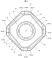
- FIG. 1 is a schematic perspective view of a cutting insert according to an embodiment of the present disclosure.
- FIG. 2 is a schematic plan view of the cutting insert shown in FIG. 1.
- FIG. 2 is a schematic side view of the cutting insert shown in FIG. 1.
- FIG. 4 is an enlarged view of section IV in FIG. 3.
- FIG. 1 is a schematic perspective view of a cutting tool according to an embodiment of the present disclosure.
- FIG. 6 is a schematic perspective view of the cutting tool shown in FIG. 5 viewed from another angle.
- FIG. 2 is a schematic diagram illustrating a method for manufacturing a cut workpiece according to an embodiment of the present disclosure.
- FIG. 2 is a schematic diagram illustrating a method for manufacturing a cut workpiece according to an embodiment of the present disclosure.
- FIG. 2 is a schematic diagram illustrating a method for manufacturing a cut workpiece according to an embodiment of the present disclosure.
- the surface accuracy of the machined surface of the workpiece can be improved.
- the insert center axis refers to a virtual axis passing through the center of the upper surface of the cutting insert and the center of the lower surface of the cutting insert.
- the term “inward direction” or “inner side” refers to a direction toward or toward the insert central axis in the cutting insert.
- the term “outward direction” or “outside” refers to a direction away from or a side away from the center axis of the cutting insert in the cutting insert.
- Orthogonality is not limited to exact orthogonality, but means to allow an error of approximately ⁇ 5 degrees.
- Parallel is not limited to exact parallel, but means to allow an error of about ⁇ 5 degrees.
- FIG. 1 is a schematic perspective view of a cutting insert 10 according to an embodiment of the present disclosure.
- FIG. 2 is a schematic plan view of the cutting insert 10 shown in FIG. 1.
- FIG. 3 is a schematic side view of the cutting insert 10 shown in FIG. 1. Note that FIG. 3 is a side view of the second side, which will be described later, viewed from the front.
- FIG. 4 is an enlarged view of section IV in FIG. 3.
- the cutting insert 10 is a component of a cutting tool used for cutting a workpiece W (see FIG. 7) made of a metal material or the like.
- Examples of the cutting process for the work material W include shoulder cutting, groove processing, R cutting, copying, and the like.
- the cutting insert 10 may have an upper surface 12 and a lower surface 14 located on the opposite side of the upper surface 12.
- the upper surface 12 and the lower surface 14 may each have a polygonal shape, for example an octagonal shape.
- the cutting insert 10 may have a polygonal plate shape, for example, an octagonal plate shape.
- the upper surface 12 and the lower surface 14 may each have a polygonal shape other than an octagonal shape, such as a triangular shape or a quadrangular shape.
- the cutting insert 10 may have a polygonal plate shape other than the octagonal plate shape, such as a triangular plate shape or a square plate shape.
- a polygonal shape is not limited to a polygonal shape in a strict sense.
- the upper surface 12 and the lower surface 14 may each have a shape that is rotationally symmetrical by a certain angle about the insert center axis CS.
- the upper surface 12 and the lower surface 14 may have a reversely symmetrical shape.
- the cutting insert 10 may have a shape that is rotationally symmetrical by a certain angle about the insert center axis CS, or may have a shape that is invertedly symmetrical between the front and back sides.
- the cutting insert 10 may have a plurality of side surfaces 16 located between the upper surface 12 and the lower surface 14. Side surface 16 may be connected to top surface 12 and bottom surface 14. The side surface 16 may function as a relief surface and may be parallel to the insert center axis CS.
- the cutting insert 10 is a so-called negative type cutting insert with a relief angle of 0 degrees.
- the cutting insert 10 may have a mounting hole 18 penetrating from the upper surface 12 to the lower surface 14.
- One opening of the attachment hole 18 may be located at the center of the upper surface 12, and the other opening of the attachment hole 18 may be located at the center of the lower surface 14.
- the center axis of the attachment hole 18 may coincide with the insert center axis CS.
- the cutting insert 10 may have an upper cutting edge 20 and a lower cutting edge 22.
- the upper cutting edge 20 may be located at the intersection of the upper surface 12 and the side surface 16.
- the lower cutting edge 22 may be located at the intersection of the lower surface 14 and the side surface 16.
- the cutting insert 10 may be a double-sided insert having an upper cutting edge 20 and a lower cutting edge 22.
- the upper cutting edge 20 may be located at the entire intersection of the upper surface 12 and the side surface 16, or may be located at a portion of the intersection.
- the lower cutting edge 22 may be located at the entire intersection of the lower surface 14 and the side surface 16, or may be located at a portion of the intersection.
- the polygonal top surface 12 may have a first corner 24 as one of the plurality of corners, and a second corner 26 as another one of the plurality of corners.
- the first corner 24 and the second corner 26 may each have a convex curved shape that projects outward in a top view.
- the top surface 12 has a first side 28 connected to the first corner 24 and a second side 30 connected to the first corner 24 on the opposite side of the first side 28. and may have.
- the second corner 26 may be connected to the second side 30 on the opposite side from the first corner 24 .
- the first side 28 may have a linear shape in a top view, or may approach the lower surface 14 as it moves away from the first corner 24 in a side view.
- the second side 30 may have a linear shape when viewed from above.
- first side 28 and the second side 30 are not limited to a linear shape, but may have a gently convex curved shape that protrudes outward, for example.
- “having a gentle convex curve shape” means that the radius of curvature is larger than the radius of curvature of the first corner 24 and the second corner 26, which are convex curve shapes.
- the upper surface 12 has a shape that is rotationally symmetrical by a certain angle about the insert center axis CS
- the upper surface 12 has a plurality of first corners 24 and a plurality of second corners 26, as shown in the example shown in FIG. It may have.
- the plurality of first corners 24 and the plurality of second corners 26 may be alternately located along the circumferential direction of the upper surface 12.
- the upper surface 12 may have a plurality of first sides 28 and a plurality of second sides 30.
- the upper surface 12 has a plurality of first corners 24, a plurality of second corners 26, a plurality of first sides 28, and a plurality of second sides 30, these are arranged so that the above-mentioned positional relationship is achieved.
- the radius of curvature which will be described later, may be evaluated by focusing on the parts extracted one by one.
- the upper surface 12 may have a land portion 32 located at its peripheral edge, and the land portion 32 may be connected to the upper cutting edge 20.
- the land portion 32 may have a function of increasing the strength of the cutting edge of the upper cutting blade 20.
- the land portion 32 may be a portion adjacent to the upper cutting edge 20 and shown as a straight line in a cross section perpendicular to the upper cutting edge 20 when viewed from above.
- the upper surface 12 may have a rake surface 34 located inside the land portion 32, and the rake surface 34 may be connected to the land portion 32.
- the rake face 34 may be inclined with respect to the land portion 32, and may approach the lower surface 14 as it moves away from the land portion 32.
- the top surface 12 may have a flat bottom surface 36 located inside the rake surface 34, and the bottom surface 36 may be connected to the rake surface 34.
- the bottom surface 36 may surround the opening of the attachment hole 18 and may be perpendicular to the insert center axis CS.
- the upper cutting edge 20 may have a main cutting edge 38 located on the first side 28.
- the main cutting edge 38 is a portion that can function as a main cutting edge in cutting the workpiece W.
- the main cutting edge 38 may be located on the entire first side 28 or may be located on a part of the first side 28.
- the main cutting edge 38 may have a linear shape when viewed from above.
- the upper cutting edge 20 may have a sub-cutting edge 40 located on the second side 30.
- the auxiliary cutting edge 40 may have a function as a wiper edge for finishing the machined surface of the workpiece W.
- the auxiliary cutting edge 40 may be located on the entire second side 30 or may be located on a part of the second side 30.
- the auxiliary cutting edge 40 may have a linear shape when viewed from above.
- the upper cutting blade 20 may have a first connecting blade (connecting blade) 42 located at the first corner 24, and the first connecting blade 42 has a main cutting blade. It may be connected to the blade 38 and the auxiliary cutting edge 40.
- the first connecting blade 42 may have a convex curved shape that protrudes outward in a top view.
- the upper cutting edge 20 may have a second connecting blade 44 located at the second corner 26, and the second connecting blade 44 may be connected to the auxiliary cutting edge 40.
- the second connecting blade 44 may have a convex curved shape that protrudes outward in a top view.
- the auxiliary cutting edge 40 may have a convex curved shape that protrudes upward in side view.
- the auxiliary cutting edge 40 includes a first portion 40a including a top portion 40t that protrudes most upwardly in the auxiliary cutting edge 40, and a second portion 40b located between the first portion 40a and the first connecting blade 42. , and a third portion 40c located between the second portion 40b and the first connecting blade 42.
- the length Lb of the second portion 40b of the auxiliary cutting edge 40 may be longer than the length La of the first portion 40a and the length Lc of the third portion 40c. good.
- the length of the third portion 40c of the auxiliary cutting edge 40 may be longer than the length of the first portion 40a.
- the second portion 40b and the third portion 40c of the auxiliary cutting edge 40 may each approach the lower surface 14 as they move away from the first portion 40a.
- the above-mentioned “length La” means the width of the first portion 40a in the direction perpendicular to the insert center axis CS when the insert 10 is viewed from the side.
- the above-mentioned “length Lb” means the width of the second portion 40b in the direction perpendicular to the insert center axis CS when the insert 10 is viewed from the side
- the above-mentioned “length Lc” means the width of the third portion 40c in the direction orthogonal to the insert center axis CS when the insert 10 is viewed from the side.
- the radius of curvature Rb of the second portion 40b of the auxiliary cutting edge 40 when viewed from the side, may be larger than the radius of curvature Ra of the first portion 40a and the radius of curvature Rc of the third portion 40c. good.
- the curvature of the second portion 40b of the auxiliary cutting edge 40 may be smaller than the curvature of the first portion 40a and the curvature of the third portion 40c.
- the radius of curvature Rc of the third portion 40c of the auxiliary cutting edge 40 may be larger than the radius of curvature Ra of the first portion 40a.
- the curvature of the third portion 40c of the sub-cutting edge 40 may be smaller than the curvature of the first portion 40a.
- the distance D1 from the top 40t of the auxiliary cutting edge 40 to the second corner 26 may be shorter than the distance D2 from the top 40t to the second portion 40b.
- the radius of curvature Ra of the first portion 40a, the radius of curvature Rb of the second portion 40b, and the radius of curvature Rc of the third portion 40c of the auxiliary cutting edge 40 are schematically illustrated.
- the boundary 12e between the second side 30 and the first corner 24 may be closer to the lower surface 14 than the boundary 12p between the second side 30 and the second corner 26.
- the first corner 24 may have a first connection region 24a connected to the second side 30, and the first connection region 24a may have a concave curve shape depressed downward in side view. good.
- the second corner 26 may have a second connection region 26a connected to the second side 30, and the second connection region 26a may have a convex curved shape projecting upward in a side view.
- the positions of the boundary 12e and the boundary 12p may be specified by viewing the cutting insert 10 from above. For example, if the first corner 24 and the second corner 26 have a convex curve shape when viewed from above and the second side 30 has a straight line shape, a virtual straight line is set along the second side 30, and this virtual straight line is set along the second side 30. The portions that are away from the straight line may be regarded as the boundary 12e and the boundary 12p. Further, in a case where the first corner 24 and the second corner 26 have a convex curve shape when viewed from above and the second side 30 has a gentle convex curve shape, a virtual arc is set along the second side 30. , the portions away from this virtual arc may be regarded as the boundary 12e and the boundary 12p.
- the lower surface 14 when the upper surface 12 and the lower surface 14 have a reversely symmetrical shape, the lower surface 14 includes the first corner 24, the second corner 26, and the first side of the upper surface 12. 28, the second side 30, the land portion 32, and the rake face 34.
- the structure of the parts corresponding to the first corner 24, second corner 26, first side 28, second side 30, land portion 32, and rake face 34 on the lower surface 14 is that the vertical positional relationship is reversed. Except for this, the configurations of the first corner 24, second corner 26, first side 28, second side 30, land portion 32, and rake surface 34 on the top surface 12 may be the same.
- the lower cutting edge 22 has the main cutting edge 38, the minor cutting edge 40, It may have portions corresponding to the first connecting blade 42 and the second connecting blade 44.
- the configuration of the parts of the lower cutting edge 22 corresponding to the main cutting edge 38, the auxiliary cutting edge 40, the first connecting blade 42, and the second connecting blade 44 is the same as that of the upper cutting edge, except that the vertical positional relationship is reversed.
- the configurations of the main cutting edge 38, the auxiliary cutting edge 40, the first connecting blade 42, and the second connecting blade 44 in No. 20 may be the same.
- Examples of the material of the cutting insert 10 include cemented carbide or cermet.
- Examples of the composition of cemented carbide include WC-Co, which is produced by adding cobalt (Co) powder to tungsten carbide (WC) and sintering it, and WC-Co, which is produced by adding titanium carbide (TiC) to WC-Co.
- TiC-Co or WC-TiC-TaC-Co, which is obtained by adding tantalum carbide (TaC) to WC-TiC-Co.
- cermet is a sintered composite material in which a metal is combined with a ceramic component, and specifically, a sintered composite material whose main component is a titanium compound such as titanium carbide (TiC) or titanium nitride (TiN). can be mentioned.
- TiC titanium carbide
- TiN titanium nitride
- the surface of cutting insert 10 may be coated with a film using chemical vapor deposition (CVD) or physical vapor deposition (PVD) methods.
- CVD chemical vapor deposition
- PVD physical vapor deposition
- the composition of the film include titanium carbide (TiC), titanium nitride (TiN), titanium carbonitride (TiCN), and alumina (Al 2 O 3 ).
- the auxiliary cutting edge 40 has a convex curved shape that projects upward in side view.
- the second portion 40b and the third portion 40c of the auxiliary cutting edge 40 approach the lower surface 14 as they move away from the first portion 40a.
- the radius of curvature Rb of the second portion 40b of the auxiliary cutting edge 40 is larger than the radius of curvature Ra of the first portion 40a and the radius of curvature Rc of the third portion 40c.
- the second part 40b which is a gently curved part, is arranged at the center of the auxiliary cutting edge 40
- the first part 40a which is a slightly steeply curved part
- the third part 40a which are slightly curved parts
- Portion 40c can be located. Therefore, even if the axial rake angle of the cutting insert 10 is set to a negative value, a wide area from the first portion 40a to the third portion 40c of the auxiliary cutting edge 40 can be used as a wiper edge.
- the surface accuracy (surface roughness) of the machined surface of the workpiece can be improved.
- the first portion 40a including the top portion 40t is a slightly steeply curved portion, the auxiliary cutting edge 40 bites into the workpiece W well, and the surface accuracy of the machined surface of the workpiece W is improved. can be improved.
- the third portion 40c located closest to the first connecting blade 42 is a slightly steep curved portion. Therefore, according to the example of the embodiment of the present disclosure, the subsequent cutting insert 10 bites into the workpiece W well during the cutting process, ensures the thickness of the chips, and prevents the occurrence of so-called peeling. can be reduced.
- the gentle portion of the auxiliary cutting edge 40 becomes longer, and the workpiece W
- the surface accuracy of the machined surface can be further improved.
- the length of the second portion 40b of the auxiliary cutting edge 40 is It can be made long enough. Thereby, according to the example of the embodiment of the present disclosure, the surface accuracy of the machined surface of the workpiece W can be further improved.
- the third portion 40c of the auxiliary cutting edge 40 When the length of the third portion 40c of the auxiliary cutting edge 40 is longer than the length of the first portion 40a, the third portion 40c, which is the next gentler portion of the auxiliary cutting edge 40 after the first portion 40a, is It can be made longer than the first portion 30a. Thereby, according to the example of the embodiment of the present disclosure, the surface accuracy of the machined surface of the workpiece W can be further improved.
- the flank surface of the side surface 16 connected to the second corner 26 is It becomes difficult to contact the machined surface of the workpiece W. Thereby, according to the example of the embodiment of the present disclosure, the durability of the cutting insert 10 can be improved.
- the workpiece When the boundary 12e between the second side 30 and the first corner 24 is closer to the lower surface 14 than the boundary 12p between the second side 30 and the second corner 26, the workpiece is It can be brought into contact with W gradually, and a sudden increase in cutting resistance can be suppressed. Thereby, according to the example of the embodiment of the present disclosure, the durability of the cutting insert 10 can be improved.
- FIG. 5 is a schematic perspective view of a cutting tool 46 according to an embodiment of the present disclosure.
- FIG. 6 is a schematic perspective view of the cutting tool 46 shown in FIG. 5 viewed from another angle.
- the cutting tool 46 is a tool that is used for cutting a workpiece W (see FIG. 7) and is rotatable around the rotation axis RS. be.
- the cutting tool 46 may include a holder 48 that is attached to the main shaft of a processing machine such as a milling machine.
- the holder 48 may have a cylindrical shape extending from the first end 48a to the second end 48b along the rotation axis RS.
- Examples of the material of the holder 48 include metals such as stainless steel, carbon steel, cast iron, and aluminum alloy.
- a plurality of pockets 50 may be located on the outer peripheral surface of the holder 48 at intervals in the circumferential direction.
- the plurality of pockets 50 may be located at equal intervals in the circumferential direction, or may be located at irregular intervals in the circumferential direction.
- the number of pockets 50 may be one.
- the cutting tool 46 may have a cutting insert 10 located in a pocket 50 of the holder 48.
- the cutting insert 10 may be located only in selected pockets 50 in the holder 48. Further, the cutting insert 10 may be fixed to the pocket 50 of the holder 48 by a fixing screw 52 inserted through the mounting hole 18.
- the cutting insert 10 may be secured to the pocket 50 of the holder 48 by a clamping member.
- the lower surface 14 may be used as a seating surface for attaching to the holder 48 (see FIG. 3).
- the upper surface 12 may be used as a seating surface (see FIG. 3).
- FIGS. 7 to 9 are schematic diagrams illustrating a method for manufacturing a cut workpiece according to an embodiment of the present disclosure.
- the method for manufacturing a cut workpiece according to the embodiment of the present disclosure is a method for manufacturing a cut workpiece M that is a cut workpiece W that has been subjected to cutting processing. , a first step, a second step, and a third step.
- the first step is a step of rotating the cutting tool 46.
- the second step is a step of bringing the rotating cutting tool 46 into contact with the workpiece W.
- the third step is a step of separating the cutting tool 46 from the workpiece W.
- Examples of the material of the work material W include aluminum alloy, stainless steel, carbon steel, alloy steel, cast iron, and non-ferrous metals.
- the cutting tool 46 is rotated in the rotational direction T and moved in the direction of the arrow FD to approach the workpiece W. Then, the cutting insert 10 of the rotating cutting tool 46 is moved in the direction of arrow FD while being brought into contact with the workpiece W. Thereby, the cutting tool 46 performs the cutting process on the workpiece W, and as in the example shown in FIG. 9, a machined surface Wf is formed on the workpiece.
- the cutting tool 46 is further moved in the direction of the arrow FD and separated from the workpiece W. Thereby, cutting of the work material W is completed, and a cut workpiece M, which is the cut material W that has been cut, can be manufactured. Since the cutting tool 46 has excellent cutting ability for the reason mentioned above, it is possible to manufacture a cut workpiece M with excellent processing accuracy.
- the cutting insert 10 of the cutting tool 46 may be repeatedly brought into contact with different parts of the workpiece W while the cutting tool 46 is being rotated.
- the cutting tool 46 is brought close to the workpiece W, but since it is sufficient that the cutting tool 46 and the workpiece W are relatively close to each other, for example, the workpiece W is brought close to the cutting tool 46. It's okay. In this regard, when separating the cutting tool 46 from the workpiece W, the same procedure is performed.
- Cutting insert 12 Top surface 12e Boundary between second side and first corner 12p Boundary between second side and second corner 14 Bottom surface 16 Side surface 18 Mounting hole 20 Upper cutting edge 22 Lower cutting edge 24 First corner 24a First connection area 26 Second corner 26a Second connection area 28 First side 30 Second side 32 Land part 34 Rake face 36 Bottom face 38 Main cutting edge 40 Minor cutting edge 40a First part 40b Second part 40c Third part 40t Top part 42 First Connecting blade 44 Second connecting blade 46 Cutting tool 50 Pocket 52 Fixing screw CS Insert center axis RS Rotating axis
Abstract
Selon un mode de réalisation de l'invention, une arête tranchante secondaire d'une plaquette de coupe, possède : une première portion prenant une forme de courbe convexe en saillie dans une direction vers le haut dans une vue latérale, et contenant une partie sommet la plus en saillie dans une direction vers le haut au niveau de l'arête tranchante secondaire ; une seconde portion positionnée entre la première portion et une arête de connexion ; et une troisième portion positionnée entre la seconde portion et l'arête de connexion. La seconde et la troisième portion s'approchent chacune d'une face fond au fur-et-à-mesure de leur éloignement vis-à-vis de la première portion. Dans une vue latérale, le rayon de courbure de la seconde portion est supérieur au rayon de courbure de la première portion et au rayon de courbure de la troisième portion.
Applications Claiming Priority (2)
| Application Number | Priority Date | Filing Date | Title |
|---|---|---|---|
| JP2022-040642 | 2022-03-15 | ||
| JP2022040642 | 2022-03-15 |
Publications (1)
| Publication Number | Publication Date |
|---|---|
| WO2023176618A1 true WO2023176618A1 (fr) | 2023-09-21 |
Family
ID=88023121
Family Applications (1)
| Application Number | Title | Priority Date | Filing Date |
|---|---|---|---|
| PCT/JP2023/008795 WO2023176618A1 (fr) | 2022-03-15 | 2023-03-08 | Plaquette de coupe, outil de coupe, et procédé de fabrication d'article usiné par coupe |
Country Status (1)
| Country | Link |
|---|---|
| WO (1) | WO2023176618A1 (fr) |
Citations (3)
| Publication number | Priority date | Publication date | Assignee | Title |
|---|---|---|---|---|
| WO2013077443A1 (fr) * | 2011-11-25 | 2013-05-30 | 住友電工ハ-ドメタル株式会社 | Plaquette de coupe indexable pour le fraisage |
| JP2014524365A (ja) * | 2011-08-26 | 2014-09-22 | セラティチット オーストリア ゲゼルシャフト ミット ベシュレンクテル ハフツング | フライス用両面切削インサート |
| WO2020045438A1 (fr) * | 2018-08-30 | 2020-03-05 | 三菱マテリアル株式会社 | Plaquette de coupe et outil de coupe du type à remplacement de bord de coupe |
-
2023
- 2023-03-08 WO PCT/JP2023/008795 patent/WO2023176618A1/fr unknown
Patent Citations (3)
| Publication number | Priority date | Publication date | Assignee | Title |
|---|---|---|---|---|
| JP2014524365A (ja) * | 2011-08-26 | 2014-09-22 | セラティチット オーストリア ゲゼルシャフト ミット ベシュレンクテル ハフツング | フライス用両面切削インサート |
| WO2013077443A1 (fr) * | 2011-11-25 | 2013-05-30 | 住友電工ハ-ドメタル株式会社 | Plaquette de coupe indexable pour le fraisage |
| WO2020045438A1 (fr) * | 2018-08-30 | 2020-03-05 | 三菱マテリアル株式会社 | Plaquette de coupe et outil de coupe du type à remplacement de bord de coupe |
Similar Documents
| Publication | Publication Date | Title |
|---|---|---|
| KR101700703B1 (ko) | 절삭 인서트 및 절삭 공구 그리고 그것을 이용한 절삭 가공물의 제조 방법 | |
| US9884378B2 (en) | Cutting insert, cutting tool, and method of manufacturing machined product | |
| US20150165532A1 (en) | Cutting insert, cutting tool, and method of producing machined product | |
| CN108698143B (zh) | 切削工具用刀具 | |
| JP6185376B2 (ja) | 切削インサート、切削工具および被削加工物の製造方法 | |
| JP6470405B2 (ja) | 切削インサート、切削工具及びこれを用いた切削加工物の製造方法 | |
| CN110944777B (zh) | 切削刀片、切削工具以及切削加工物的制造方法 | |
| WO2023176618A1 (fr) | Plaquette de coupe, outil de coupe, et procédé de fabrication d'article usiné par coupe | |
| JP7281532B2 (ja) | 旋削工具及び切削加工物の製造方法 | |
| JP7114733B2 (ja) | 切削インサート、切削工具及び切削加工物の製造方法 | |
| JP7045460B2 (ja) | 切削工具及び切削加工物の製造方法 | |
| WO2023176619A1 (fr) | Plaquette de coupe, outil de coupe, et procédé de fabrication d'article usiné par coupe | |
| JP6825854B2 (ja) | 切削工具及び切削加工物の製造方法 | |
| JP6711842B2 (ja) | 切削インサート、切削工具及び切削加工物の製造方法 | |
| JP2020172005A (ja) | 切削インサート、切削工具、及び切削加工物の製造方法 | |
| WO2021193705A1 (fr) | Outil rotatif et procédé de fabrication de pièces coupées | |
| JP6616176B2 (ja) | 切削工具 | |
| JP7223773B2 (ja) | 回転工具及び切削加工物の製造方法 | |
| WO2023228741A1 (fr) | Outil de coupe et procédé de production de pièce coupée | |
| JP7344168B2 (ja) | 切削インサート、切削工具及び切削加工物の製造方法 | |
| KR102540681B1 (ko) | 절삭 인서트, 절삭 공구 및 절삭 가공물의 제조 방법 | |
| WO2024048257A1 (fr) | Plaquette de coupe, outil de coupe et procédé de fabrication de pièce coupée | |
| JP6717951B2 (ja) | 切削インサート、切削工具及び切削加工物の製造方法 | |
| JP2012232351A (ja) | 切削インサートおよび切削工具ならびにそれを用いた被削材の切削方法 | |
| JP2017064869A (ja) | 切削インサート、切削工具及びそれを用いた切削加工物の製造方法 |
Legal Events
| Date | Code | Title | Description |
|---|---|---|---|
| 121 | Ep: the epo has been informed by wipo that ep was designated in this application |
Ref document number: 23770574 Country of ref document: EP Kind code of ref document: A1 |