WO2023089973A1 - カテーテル - Google Patents
カテーテル Download PDFInfo
- Publication number
- WO2023089973A1 WO2023089973A1 PCT/JP2022/037002 JP2022037002W WO2023089973A1 WO 2023089973 A1 WO2023089973 A1 WO 2023089973A1 JP 2022037002 W JP2022037002 W JP 2022037002W WO 2023089973 A1 WO2023089973 A1 WO 2023089973A1
- Authority
- WO
- WIPO (PCT)
- Prior art keywords
- connector
- catheter
- tube
- insertion hole
- catheter tube
- Prior art date
- Legal status (The legal status is an assumption and is not a legal conclusion. Google has not performed a legal analysis and makes no representation as to the accuracy of the status listed.)
- Ceased
Links
Images




Classifications
-
- A—HUMAN NECESSITIES
- A61—MEDICAL OR VETERINARY SCIENCE; HYGIENE
- A61M—DEVICES FOR INTRODUCING MEDIA INTO, OR ONTO, THE BODY; DEVICES FOR TRANSDUCING BODY MEDIA OR FOR TAKING MEDIA FROM THE BODY; DEVICES FOR PRODUCING OR ENDING SLEEP OR STUPOR
- A61M25/00—Catheters; Hollow probes
- A61M25/0009—Making of catheters or other medical or surgical tubes
- A61M25/0014—Connecting a tube to a hub
-
- A—HUMAN NECESSITIES
- A61—MEDICAL OR VETERINARY SCIENCE; HYGIENE
- A61M—DEVICES FOR INTRODUCING MEDIA INTO, OR ONTO, THE BODY; DEVICES FOR TRANSDUCING BODY MEDIA OR FOR TAKING MEDIA FROM THE BODY; DEVICES FOR PRODUCING OR ENDING SLEEP OR STUPOR
- A61M25/00—Catheters; Hollow probes
- A61M25/0043—Catheters; Hollow probes characterised by structural features
-
- A—HUMAN NECESSITIES
- A61—MEDICAL OR VETERINARY SCIENCE; HYGIENE
- A61M—DEVICES FOR INTRODUCING MEDIA INTO, OR ONTO, THE BODY; DEVICES FOR TRANSDUCING BODY MEDIA OR FOR TAKING MEDIA FROM THE BODY; DEVICES FOR PRODUCING OR ENDING SLEEP OR STUPOR
- A61M25/00—Catheters; Hollow probes
- A61M25/0097—Catheters; Hollow probes characterised by the hub
-
- A—HUMAN NECESSITIES
- A61—MEDICAL OR VETERINARY SCIENCE; HYGIENE
- A61M—DEVICES FOR INTRODUCING MEDIA INTO, OR ONTO, THE BODY; DEVICES FOR TRANSDUCING BODY MEDIA OR FOR TAKING MEDIA FROM THE BODY; DEVICES FOR PRODUCING OR ENDING SLEEP OR STUPOR
- A61M39/00—Tubes, tube connectors, tube couplings, valves, access sites or the like, specially adapted for medical use
- A61M39/10—Tube connectors; Tube couplings
-
- A—HUMAN NECESSITIES
- A61—MEDICAL OR VETERINARY SCIENCE; HYGIENE
- A61M—DEVICES FOR INTRODUCING MEDIA INTO, OR ONTO, THE BODY; DEVICES FOR TRANSDUCING BODY MEDIA OR FOR TAKING MEDIA FROM THE BODY; DEVICES FOR PRODUCING OR ENDING SLEEP OR STUPOR
- A61M25/00—Catheters; Hollow probes
- A61M2025/0098—Catheters; Hollow probes having a strain relief at the proximal end, e.g. sleeve
Definitions
- the present disclosure relates to catheters.
- a catheter generally includes a catheter tube to be introduced into the body and a connector connected to the proximal end of the catheter tube (see Patent Document 1, for example).
- the connector has an insertion hole into which the proximal end of the catheter tube is inserted, and the proximal end inserted into the insertion hole is joined to the connector by welding or adhesion.
- the tube lead-out part of the catheter tube led out from the insertion hole to the tip side may be bent with respect to the joint part joined to the connector.
- the catheter tube may bend at the boundary between the joint with the connector and the tube lead-out portion, resulting in a kink.
- the catheter tube has a large difference in hardness between the joining portion and the tube lead-out portion, kinking is likely to occur at the boundary between them.
- the present disclosure has been made in view of the above circumstances, and a main object thereof is to provide a catheter capable of suppressing the occurrence of kinks.
- the catheter of the first disclosure includes a catheter tube and a connector connected to the proximal end of the catheter tube, the connector into which the proximal end of the catheter tube is inserted.
- a catheter that has an insertion hole and is joined to the proximal end portion inserted into the insertion hole, wherein the connector is provided on the distal side of the insertion hole and extends from the insertion hole in the catheter tube. It has a cylindrical or ring-shaped enclosing part that encloses a part of the tube lead-out part led out to the distal end side at a position spaced apart from the tube lead-out part.
- the proximal end of the catheter tube is joined to the connector while being inserted into the insertion hole of the connector.
- a part of the tube lead-out portion led out from the insertion hole in the catheter tube to the distal side is surrounded by the enclosing portion of the connector.
- the tube lead-out portion is bent when the catheter is introduced into the body, the amount of bending is limited by the surrounding portion. As a result, it is possible to suppress the occurrence of kinks in the catheter tube at the boundary between the connecting portion with the connector and the tube lead-out portion.
- a catheter according to a second disclosure is the catheter according to the first disclosure, wherein the connector has a main body portion in which the insertion hole is formed, and a cylindrical extension portion extending from the main body portion toward the distal end, and The extending portion serves as the enclosing portion.
- the connector has a main body portion in which an insertion hole is formed, and a cylindrical extension portion extending from the main body portion toward the distal end side, and the extension portion is a tube lead-out portion. It is an enclosure that surrounds a part of the In this case, the load acting on the extending portion (surrounding portion) can be stably received.
- the inner surface of the extension portion includes a tapered surface whose diameter is increased toward the distal end side.
- the tube lead-out portion of the catheter tube when the tube lead-out portion of the catheter tube is bent, the tube lead-out portion can be brought into contact along the tapered surface of the extension. Therefore, it is possible to suppress the occurrence of stress concentration in the tube lead-out portion, and as a result, it is possible to suppress the occurrence of kinks due to the stress concentration.
- the tapered surface is continuous with the peripheral surface of the insertion hole.
- the tapered surface and the peripheral surface of the insertion hole are continuous, there is no step at the boundary between the tapered surface and the peripheral surface of the insertion hole. In this case, it is possible to more reliably prevent the catheter tube from bending at the boundary between the joint portion inserted into the insertion hole and joined to the connector and the tube lead-out portion led out from the insertion hole. Therefore, it is possible to more reliably suppress the occurrence of kinks at the boundary.
- a catheter according to a fifth disclosure is the catheter according to the second disclosure, wherein the extension portion has an inner diameter larger than the hole diameter of the insertion hole at the proximal end thereof, and the inner diameter of the extension portion It is the same from the proximal end to the distal end of the part, or it increases from the proximal end to the distal end.
- the tube lead-out portion of the catheter tube is convex in the direction perpendicular to the axial direction near the proximal end. Bending (inflating) is assumed.
- the extending portion is configured as described above, so that a wide inner space of the extending portion can be secured from the base end portion to the tip end portion. As a result, the vicinity of the base end portion of the tube lead-out portion can be naturally bent in the inner space of the extension portion, and as a result, it is possible to suppress the occurrence of a kink near the base end portion of the tube lead-out portion. becomes.
- the inner surface of the distal end portion of the surrounding portion is a curved surface portion formed so that the inner diameter increases toward the distal end.
- the tube lead-out portion may bend at the tip of the extension portion.
- the tube lead-out portion since the inner surface of the distal end of the extending portion is curved, the tube lead-out portion is bent along the curved surface at the distal end of the extending portion. Therefore, it is possible to prevent the tube lead-out portion from bending at the distal end portion of the extending portion. As a result, it is possible to suppress the occurrence of kinks due to such bending.
- a catheter according to a seventh disclosure is the catheter according to any one of the first to sixth disclosures, wherein the base end portion inserted into the insertion hole in the catheter tube is located on the distal end side of the joint portion joined to the connector. is a non-joint portion that is not joined to the connector.
- the distal end side is a non-joint portion with respect to the joint portion with the connector.
- the connector has a main body portion in which the insertion hole is formed and the surrounding portion are integrally formed.
- the main body portion having the insertion hole and the enclosing portion are integrally formed. can do.
- a catheter of a ninth disclosure is the catheter according to any one of the first to eighth disclosures, wherein the connector is formed with light transmissivity, the catheter tube is formed with light absorption, and the The connector is welded to the proximal end of the catheter tube.
- the connector has optical transparency and the catheter tube has optical absorption.
- the interface between the connector and the catheter tube can be laser-welded.
- the thickness of the welded portion between the connector and the catheter tube can be made relatively thin, and as a result, the difference in hardness between the joint portion (welded portion) with the connector and the tube lead-out portion of the catheter tube can be reduced. can be done. Therefore, it is possible to further suppress the occurrence of kinks due to differences in hardness.
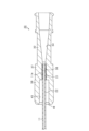
- FIG. 2 is a cross-sectional view showing the vicinity of a junction between a catheter tube and a connector in a catheter according to the first embodiment; Sectional drawing for demonstrating the effect
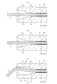
- FIG. 10 is a cross-sectional view showing the vicinity of a junction between a catheter tube and a connector in a catheter according to the second embodiment; Sectional drawing for demonstrating the effect
- FIG. 1 is a cross-sectional view showing the vicinity of a junction between a catheter tube 11 and a connector 12 in a catheter 10.
- FIG. 1 is a cross-sectional view showing the vicinity of a junction between a catheter tube 11 and a connector 12 in a catheter 10.
- the catheter 10 includes a catheter tube 11 and a connector 12 connected to the base end (proximal end) of the catheter tube 11 .
- the catheter tube 11 is formed in the shape of a circular tube and has a lumen 13 therein extending along the entire axial direction.
- the catheter tube 11 is made of a flexible soft resin, such as polyamide.
- the catheter tube 11 is colored black and has light absorbability.
- the catheter 10 is, for example, an imaging catheter.
- the catheter 10 may be another catheter such as a balloon catheter or an aspiration catheter.
- the connector 12 is made of hard resin, such as polyamide.
- the connector 12 is formed in a circular tubular shape as a whole and has a hole portion 14 passing through the connector 12 in the axial direction.
- the connector 12 is formed with transparency or translucency, and has light transmittance. Note that the connector 12 is also called a hub.
- the connector 12 may be made of hard resin other than polyamide, such as polyacetal, polycarbonate, and ABS.
- the connector 12 has a body portion 17 formed with an insertion hole 16 into which the proximal end portion 11a of the catheter tube 11 is inserted, and an extension portion 18 extending from the body portion 17 toward the distal side.
- the insertion hole 16 forms part of the hole portion 14 and has a hole diameter substantially equal to the outer diameter of the catheter tube 11 .
- the insertion hole 16 has the same hole diameter over the entire area in the axial direction.
- the proximal end portion 11a of the catheter tube 11 inserted into the insertion hole 16 is joined to the body portion 17 by welding.
- the base end portion 11a of the catheter tube 11 is joined to the main body portion 17 by laser welding.
- the body portion 17 and the proximal end portion 11a of the catheter tube 11 are laser-welded at their interface. Laser welding will now be described. A laser beam is applied via the connector 12 to the interface between the main body portion 17 and the proximal end portion 11 a of the catheter tube 11 . Then, heat is generated at the interface by the irradiated laser beam, and the generated heat melts the main body portion 17 and the base end portion 11a, thereby welding them together.
- the body portion 17 extends to the proximal end side from the insertion hole 16 and includes the proximal end portion of the connector 12 .
- the body portion 17 is formed with a tapered hole 23 extending from the insertion hole 16 toward the proximal side, and a connection hole 24 extending from the tapered hole 23 toward the proximal side.
- the tapered hole 23 and the connection hole 24 form part of the hole portion 14 together with the insertion hole 16 .
- the tapered hole 23 widens toward the proximal end, and the connection hole 24 is open at the proximal end of the connector 12 .
- Another connector can be connected to the connection hole 24 .
- the extension part 18 extends from the distal end portion of the main body portion 17 toward the distal end side and has a cylindrical shape.
- the extension length L1 of the extension portion 18 is longer than the length L2 (length in the axial direction) of the joint portion 21 of the catheter tube 11 that is joined to the main body portion 17 .
- the extending portion 18 has an outer diameter that is substantially constant over the entire axial direction, while an inner diameter that increases continuously from the base end side to the tip end side.
- the inner diameter of the extending portion 18 is larger than the hole diameter of the insertion hole 16 , in other words, larger than the outer diameter of the catheter tube 11 .
- the inner diameter of the distal end portion of the extending portion 18 is larger than twice the outer diameter of the catheter tube 11 .
- the extending portion 18 can also be referred to as an enlarged diameter portion.
- the inner surface of the extending portion 18 is a tapered surface 26 whose diameter is increased from the base end side to the tip end side.
- the tapered surface 26 expands in diameter from the peripheral surface 16a of the insertion hole 16 toward the distal end side. Therefore, the tapered surface 26 and the peripheral surface 16a of the insertion hole 16 are continuous at their boundary.
- An inner space 25 is formed inside the extending portion 18 .
- the inner space 25 communicates with the insertion hole 16 and forms part of the hole portion 14 .
- the inner space 25 is opened toward the distal end side.
- a tube lead-out portion 22 led out from the insertion hole 16 in the catheter tube 11 to the tip side extends through the inner space 25 to the tip side.
- part of the tube lead-out portion 22 is surrounded by the extension portion 18 .
- the tube lead-out portion 22 and the extension portion 18 are separated from each other. Note that the extending portion 18 corresponds to the "surrounding portion".
- the inner surface of the distal end portion of the extending portion 18 is a curved surface portion 28 formed in a curved surface shape so that the inner diameter increases toward the distal end.
- the curved surface portion 28 smoothly connects the tip surface of the extension portion 18 and the tapered surface 26 .
- the curvature radius of the curved surface portion 28 is larger than the outer diameter radius of the catheter tube 11 .
- the curvature radius of the curved surface portion 28 is larger than the outer diameter radius of the catheter tube 11 over the entire curved surface portion 28 .
- a portion of the curved surface portion 28 may have a curvature radius equal to or less than the outer diameter radius of the catheter tube 11 .
- FIG. 2 is a cross-sectional view for explaining the action of the extending portion 18. As shown in FIG.
- the tube lead-out portion 22 led out from the insertion hole 16 in the catheter tube 11 is joined to the connector 12 in the catheter tube 11. It may be bent with respect to the joint portion 21 .
- the tube lead-out portion 22 is brought into contact with the extension portion 18 of the connector 12 , more specifically, along the tapered surface 26 of the extension portion 18 . This abutment limits the bending amount of the tube lead-out portion 22 with respect to the joint portion 21 . Therefore, it is possible to prevent the catheter tube 11 from kinking at the boundary between the tube lead-out portion 22 and the joint portion 21 .
- the tube lead-out portion 22 is bent at the distal end portion of the extension portion 18.
- the tube lead-out portion 22 is bent along the curved surface portion 28 as shown in FIG. 2(b). Therefore, it is possible to prevent the tube lead-out portion 22 from bending at the distal end portion of the extension portion 18 . As a result, it is possible to suppress the occurrence of kinks due to such bending.
- the enclosing portion is the tubular extending portion 18 extending from the main body portion 17 of the connector 12 toward the distal end side, so that the extending portion 18 (enclosing portion) acts on the extending portion 18 .
- the above load can be received in a stable state.
- the body portion 17 and the extension portion 18 are integrally formed, it is possible to prevent the extension portion 18 from being detached from the body portion 17 due to the above load.
- the tube lead-out portion 22 Since the inner surface of the extending portion 18 is a tapered surface 26 whose diameter is enlarged toward the distal end side, the tube lead-out portion 22 is brought into contact along the tapered surface 26 when the tube lead-out portion 22 is bent. be able to. Therefore, it is possible to suppress the occurrence of stress concentration in the tube lead-out portion 22, and as a result, it is possible to suppress the occurrence of kinks due to the stress concentration.
- the catheter tube 11 is more reliably prevented from bending at the boundary between the joint portion 21 inserted into the insertion hole 16 and joined to the connector 12 and the tube lead-out portion 22 led out from the insertion hole 16. be able to. Therefore, it is possible to more reliably suppress the occurrence of kinks at the boundary.
- the connector 12 has optical transparency, and the catheter tube 11 has optical absorption.
- the interface between the connector 12 and the catheter tube 11 can be laser-welded.
- the thickness of the welded portion between the connector 12 and the catheter tube 11 can be made relatively thin. Hardness difference can be reduced. Therefore, it is possible to further suppress the occurrence of kinks due to differences in hardness.
- FIG. 3 is a cross-sectional view showing the vicinity of the junction between the catheter tube 11 and the connector 32 in the catheter 30. As shown in FIG.
- a catheter 30 of this embodiment includes a catheter tube 11 and a connector 32 connected to the proximal end portion 11a of the catheter tube 11, as in the first embodiment. Since the catheter tube 11 has the same configuration as that of the first embodiment, it is given the same reference numerals and its description is omitted.
- the connector 32 includes a body portion 37 formed with an insertion hole 36 into which the proximal end portion 11a of the catheter tube 11 is inserted, and a cylindrical extension extending from the body portion 37 to the distal side. and an outlet 38 . Since the structure of the main body part 37 is the same as that of the first embodiment, its description is omitted.
- the inner diameter of the extending portion 38 is constant from the proximal end to the distal end. Therefore, the inner surface of the extending portion 38 is a non-tapered surface extending parallel to the axial direction.
- the inner diameter of the extending portion 38 is larger than the hole diameter of the insertion hole 16 , in other words, larger than the outer diameter of the catheter tube 11 .
- the inner diameter of the extension 38 is larger than twice the outer diameter of the catheter tube 11 .
- the extending portion 38 can also be called a constant diameter portion.
- extension length of the extension portion 38 is longer than the length of the joint portion 21 of the catheter tube 11 and the connector 12, as in the first embodiment.
- a curved surface portion 48 is formed on the inner surface of the distal end portion of the extension portion 38 .
- FIG. 4 is a cross-sectional view for explaining the action of the extending portion 38. As shown in FIG.
- the tube lead-out portion 22 of the catheter tube 11 is bent with respect to the joint portion 21 when the catheter 30 is introduced into the body, the tube lead-out portion 22 is bent toward the extension portion 38 of the connector 32 . is abutted. The contact limits the amount of bending of the catheter tube 11 . Therefore, as in the first embodiment, the catheter tube 11 can be prevented from kinking at the boundary between the tube lead-out portion 22 and the joint portion 21 .
- the catheter 30 When the catheter 30 is introduced into the body, a force directed toward the proximal end may act on the catheter tube 11 .
- the tube lead-out portion 22 of the catheter tube 11 is bent in the vicinity of its proximal end so as to protrude (swell) in a direction perpendicular to the axial direction.
- the inner diameter of the extension 38 is larger than the hole diameter of the insertion hole 16 from the proximal end to the distal end of the extension 38 .
- An inner space 45 is secured widely from the proximal end to the distal end. Therefore, as shown in FIG.
- the vicinity of the base end portion of the tube lead-out portion 22 can be bent without difficulty in the inner space 45 of the extension portion 38.
- the tube lead-out portion 22 is bent at the base end portion It is possible to suppress kink in the vicinity.
- the inner surface of the extending portion 52 of the connector 50 may include a plurality of tapered surfaces 54,55.
- the tapered surfaces 54 and 55 are adjacent to each other in the axial direction of the extending portion 52, with the tapered surface 54 disposed on the proximal side and the tapered surface 55 disposed on the distal side.
- Each of the tapered surfaces 54 and 55 expands in diameter from the base end side toward the tip end side, and is continuous at the mutual boundary portion.
- the tapered surface 54 on the proximal end side is continuous with the peripheral surface 16a of the insertion hole 16 at the proximal end portion.
- the tapered surfaces 54 and 55 have different angles of inclination with respect to the axial direction of the extending portion 52 . Specifically, the inclination angle of the tapered surface 55 on the distal end side is larger than the inclination angle of the tapered surface 54 on the proximal end side.
- the inclination angle of the tapered surface 54 on the proximal end side is small, bending of the tube lead-out portion 22 of the catheter tube 11 with respect to the joint portion 21 can be further suppressed. Therefore, the occurrence of kinks can be further suppressed.
- the tapered surface 55 on the distal end side has a large inclination angle, it is possible to sufficiently secure the bending amount of the tube lead-out portion 22 while suppressing the occurrence of kinks.
- the inner surface of the extending portion 62 of the connector 60 may include a curved surface 63.
- the curved surface 63 is formed over the entire length of the extending portion 62 in the axial direction.
- the curved surface 63 is formed such that the inner diameter increases from the proximal side to the distal side, and the curvature increases from the proximal side to the distal side. According to such a configuration, it is possible to obtain the same effect as the configuration (1) above.
- the extending portion 72 of the connector 70 may include a constant diameter portion 73 and an enlarged diameter portion 74, respectively.
- a constant diameter portion 73 is provided on the distal end side of the extension portion 72 and an enlarged diameter portion 74 is provided on the proximal end side of the extension portion 72 .
- the equal diameter portion 73 has a constant inner diameter. Therefore, the inner surface of the constant diameter portion 73 is a non-tapered surface 76 extending parallel to the axial direction of the extension portion 72 . Also, the inner diameter of the constant diameter portion 73 is larger than the hole diameter of the insertion hole 16 .
- the inner diameter of the expanded diameter portion 74 increases from the proximal side toward the distal side. Therefore, the inner surface of the enlarged diameter portion 74 is a tapered surface 77 whose diameter is enlarged toward the distal end side.
- the tapered surface 77 is continuous with the peripheral surface 16a of the insertion hole 16 at its proximal end and continuous with the non-tapered surface 76 at its distal end.
- the equal diameter portion 73 and the enlarged diameter portion 74 have approximately the same length in the axial direction.
- the tube lead-out portion 22 bends in the inner space 78 of the extension portion 72 (mainly inside the equal diameter portion 73). becomes possible. Therefore, in such a case, it is possible to suppress the occurrence of kinks.
- the extending portion 82 of the connector 80 may be provided with a protruding portion 85 protruding inward.
- the projecting portion 85 extends annularly along the circumferential direction of the extending portion 82 , and a plurality (specifically, two) of the projecting portions 85 are provided at predetermined intervals in the axial direction of the extending portion 82 .
- the protrusions 85 have the same protrusion height, but as shown in FIG. 6(b), the protrusions 86 and 87 have different protrusion heights.
- the protrusion 87 on the distal end side has a lower protrusion height than the protrusion 86 on the proximal end side. That is, in the example of FIG. 6(b), the protrusion height is lowered toward the tip side.
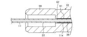
- the connector 32 is connected to the connector 32 on the distal end side of the connection portion 91 to be connected to the connector 32.
- a non-bonded portion 92 may be provided.
- the hardness difference (hardness change) between the joint portion 91 with the connector 32 and the tube lead-out portion 22 led out from the insertion hole 36 can be reduced. Therefore, it is possible to suppress the occurrence of kinks due to the difference in hardness.
- the connectors 12 and 32 are configured to have the body portions 17 and 37 and the extension portions 18 and 38, but the connector configuration is not necessarily limited to this.
- the connector has a main body, an annular enclosing part provided on the distal end side of the main body and surrounding a part of the tube lead-out part 22, and a rod-like connecting part connecting the enclosing part and the main body. may be configured.
- the tube lead-out portion 22 of the catheter tube 11 is bent, the amount of bending can be limited by the surrounding portion. Therefore, it is possible to prevent the catheter tube 11 from kinking at the boundary between the joint portion 21 and the tube lead-out portion 22 .
- the base end portion 11a of the catheter tube 11 is laser welded to the connector 12, but a welding method other than laser welding may be employed.
- the proximal end portion 11a of the catheter tube 11 may be adhered to the connector 12 using an adhesive.
- the proximal end portion 11a of the catheter tube 11 may be joined to the connector 12 by welding or adhesion.
Landscapes
- Health & Medical Sciences (AREA)
- Life Sciences & Earth Sciences (AREA)
- Heart & Thoracic Surgery (AREA)
- Biomedical Technology (AREA)
- Engineering & Computer Science (AREA)
- Anesthesiology (AREA)
- Pulmonology (AREA)
- Hematology (AREA)
- Animal Behavior & Ethology (AREA)
- General Health & Medical Sciences (AREA)
- Public Health (AREA)
- Veterinary Medicine (AREA)
- Biophysics (AREA)
- Media Introduction/Drainage Providing Device (AREA)
Priority Applications (4)
| Application Number | Priority Date | Filing Date | Title |
|---|---|---|---|
| JP2023561441A JP7607793B2 (ja) | 2021-11-16 | 2022-10-03 | カテーテル |
| KR1020237045308A KR20240013818A (ko) | 2021-11-16 | 2022-10-03 | 카테터(catheter) |
| EP22895259.4A EP4344721A4 (en) | 2021-11-16 | 2022-10-03 | CATHETER |
| US18/440,477 US20240181202A1 (en) | 2021-11-16 | 2024-02-13 | Catheter |
Applications Claiming Priority (2)
| Application Number | Priority Date | Filing Date | Title |
|---|---|---|---|
| JP2021-186242 | 2021-11-16 | ||
| JP2021186242 | 2021-11-16 |
Related Child Applications (1)
| Application Number | Title | Priority Date | Filing Date |
|---|---|---|---|
| US18/440,477 Continuation US20240181202A1 (en) | 2021-11-16 | 2024-02-13 | Catheter |
Publications (1)
| Publication Number | Publication Date |
|---|---|
| WO2023089973A1 true WO2023089973A1 (ja) | 2023-05-25 |
Family
ID=86396676
Family Applications (1)
| Application Number | Title | Priority Date | Filing Date |
|---|---|---|---|
| PCT/JP2022/037002 Ceased WO2023089973A1 (ja) | 2021-11-16 | 2022-10-03 | カテーテル |
Country Status (5)
| Country | Link |
|---|---|
| US (1) | US20240181202A1 (https=) |
| EP (1) | EP4344721A4 (https=) |
| JP (1) | JP7607793B2 (https=) |
| KR (1) | KR20240013818A (https=) |
| WO (1) | WO2023089973A1 (https=) |
Cited By (1)
| Publication number | Priority date | Publication date | Assignee | Title |
|---|---|---|---|---|
| WO2025196453A1 (en) * | 2024-03-22 | 2025-09-25 | Convatec Limited | Laser welding of catheter assembly components |
Citations (3)
| Publication number | Priority date | Publication date | Assignee | Title |
|---|---|---|---|---|
| JP2007211933A (ja) * | 2006-02-10 | 2007-08-23 | Yokohama Rubber Co Ltd:The | 樹脂配管の接続構造および接続方法 |
| JP2011510744A (ja) * | 2008-01-30 | 2011-04-07 | ベクトン・ディキンソン・アンド・カンパニー | 抗閉塞カテーテル |
| JP2013090717A (ja) | 2011-10-25 | 2013-05-16 | Goodtec Co Ltd | カテーテル |
Family Cites Families (8)
| Publication number | Priority date | Publication date | Assignee | Title |
|---|---|---|---|---|
| US4366817A (en) * | 1981-05-26 | 1983-01-04 | Burron Medical Inc. | Winged IV catheter |
| JP5595686B2 (ja) * | 2009-07-29 | 2014-09-24 | テルモ株式会社 | カテーテル収納チューブ |
| EP2574362B1 (en) * | 2010-06-30 | 2015-07-22 | Terumo Kabushiki Kaisha | Catheter |
| KR20130090717A (ko) | 2012-02-06 | 2013-08-14 | 최이호 | 후불제 방식의 차량번호 기반 주차 정산 서비스 제공 방법 |
| ES2694553T3 (es) * | 2014-01-08 | 2018-12-21 | B. Braun Melsungen Ag | Dispositivos de catéter con válvulas y métodos relacionados |
| US10493244B2 (en) * | 2015-10-28 | 2019-12-03 | Becton, Dickinson And Company | Extension tubing strain relief |
| US10737060B2 (en) * | 2016-09-14 | 2020-08-11 | Boston Scientific Scimed, Inc. | Catheter hubs |
| WO2020255736A1 (ja) * | 2019-06-19 | 2020-12-24 | 株式会社カネカ | カテーテル、及びカテーテルの製造方法 |
-
2022
- 2022-10-03 EP EP22895259.4A patent/EP4344721A4/en active Pending
- 2022-10-03 WO PCT/JP2022/037002 patent/WO2023089973A1/ja not_active Ceased
- 2022-10-03 JP JP2023561441A patent/JP7607793B2/ja active Active
- 2022-10-03 KR KR1020237045308A patent/KR20240013818A/ko active Pending
-
2024
- 2024-02-13 US US18/440,477 patent/US20240181202A1/en active Pending
Patent Citations (3)
| Publication number | Priority date | Publication date | Assignee | Title |
|---|---|---|---|---|
| JP2007211933A (ja) * | 2006-02-10 | 2007-08-23 | Yokohama Rubber Co Ltd:The | 樹脂配管の接続構造および接続方法 |
| JP2011510744A (ja) * | 2008-01-30 | 2011-04-07 | ベクトン・ディキンソン・アンド・カンパニー | 抗閉塞カテーテル |
| JP2013090717A (ja) | 2011-10-25 | 2013-05-16 | Goodtec Co Ltd | カテーテル |
Non-Patent Citations (1)
| Title |
|---|
| See also references of EP4344721A4 |
Cited By (1)
| Publication number | Priority date | Publication date | Assignee | Title |
|---|---|---|---|---|
| WO2025196453A1 (en) * | 2024-03-22 | 2025-09-25 | Convatec Limited | Laser welding of catheter assembly components |
Also Published As
| Publication number | Publication date |
|---|---|
| EP4344721A4 (en) | 2025-01-29 |
| KR20240013818A (ko) | 2024-01-30 |
| JPWO2023089973A1 (https=) | 2023-05-25 |
| EP4344721A1 (en) | 2024-04-03 |
| US20240181202A1 (en) | 2024-06-06 |
| JP7607793B2 (ja) | 2024-12-27 |
Similar Documents
| Publication | Publication Date | Title |
|---|---|---|
| JP5237572B2 (ja) | バルーンカテーテル及びその製造方法 | |
| JP5237567B2 (ja) | バルーンカテーテル | |
| US11432725B2 (en) | Optical probe and assembly thereof having specific optical component adhesive configuration | |
| US8323432B2 (en) | Catheter and method of manufacturing same | |
| JPS62113125A (ja) | 内視鏡 | |
| WO2023089973A1 (ja) | カテーテル | |
| JP5313613B2 (ja) | カテーテル | |
| CN107405469A (zh) | 导管及导管的制造方法 | |
| WO2018135533A1 (ja) | バルーンカテーテル | |
| US20070185414A1 (en) | Wire guide having distal coupling tip | |
| JP2026513462A (ja) | ソフトチップ血管内装置 | |
| JP2001149480A (ja) | カテーテルの製造方法およびカテーテル | |
| JPWO2016114207A1 (ja) | カテーテル | |
| WO2020250934A1 (ja) | カテーテル | |
| JP2535250B2 (ja) | カテ―テル | |
| JP5486618B2 (ja) | バルーンカテーテル | |
| JP5917279B2 (ja) | 医療用シャフトおよび医療用器具 | |
| CN116407738B (zh) | 一种多段管的加工方法和球囊导管 | |
| CN115414574A (zh) | 一种导管尖端、球囊导管及血管介入装置 | |
| JP2012096120A (ja) | バルーンカテーテル | |
| CN118871157A (zh) | 导管 | |
| JP5613189B2 (ja) | バルーンカテーテル | |
| JP2023038815A (ja) | ガイドワイヤ | |
| CN222368188U (zh) | 导引鞘及其扩张管、导引结构 | |
| WO2021217590A1 (zh) | 切割装置以及切割球囊 |
Legal Events
| Date | Code | Title | Description |
|---|---|---|---|
| 121 | Ep: the epo has been informed by wipo that ep was designated in this application |
Ref document number: 22895259 Country of ref document: EP Kind code of ref document: A1 |
|
| WWE | Wipo information: entry into national phase |
Ref document number: 2023561441 Country of ref document: JP |
|
| ENP | Entry into the national phase |
Ref document number: 20237045308 Country of ref document: KR Kind code of ref document: A |
|
| WWE | Wipo information: entry into national phase |
Ref document number: 2022895259 Country of ref document: EP Ref document number: 1020237045308 Country of ref document: KR |
|
| ENP | Entry into the national phase |
Ref document number: 2022895259 Country of ref document: EP Effective date: 20231228 |