WO2023085122A1 - 留め具 - Google Patents
留め具 Download PDFInfo
- Publication number
- WO2023085122A1 WO2023085122A1 PCT/JP2022/040358 JP2022040358W WO2023085122A1 WO 2023085122 A1 WO2023085122 A1 WO 2023085122A1 JP 2022040358 W JP2022040358 W JP 2022040358W WO 2023085122 A1 WO2023085122 A1 WO 2023085122A1
- Authority
- WO
- WIPO (PCT)
- Prior art keywords
- hole
- fastener
- elastic
- elastic piece
- base
- Prior art date
- Legal status (The legal status is an assumption and is not a legal conclusion. Google has not performed a legal analysis and makes no representation as to the accuracy of the status listed.)
- Ceased
Links
Images







Classifications
-
- F—MECHANICAL ENGINEERING; LIGHTING; HEATING; WEAPONS; BLASTING
- F16—ENGINEERING ELEMENTS AND UNITS; GENERAL MEASURES FOR PRODUCING AND MAINTAINING EFFECTIVE FUNCTIONING OF MACHINES OR INSTALLATIONS; THERMAL INSULATION IN GENERAL
- F16B—DEVICES FOR FASTENING OR SECURING CONSTRUCTIONAL ELEMENTS OR MACHINE PARTS TOGETHER, e.g. NAILS, BOLTS, CIRCLIPS, CLAMPS, CLIPS OR WEDGES; JOINTS OR JOINTING
- F16B21/00—Means for preventing relative axial movement of a pin, spigot, shaft or the like and a member surrounding it; Stud-and-socket releasable fastenings
- F16B21/06—Releasable fastening devices with snap-action
- F16B21/08—Releasable fastening devices with snap-action in which the stud, pin, or spigot has a resilient part
- F16B21/084—Releasable fastening devices with snap-action in which the stud, pin, or spigot has a resilient part with a series of flexible ribs or fins extending laterally from the shank of the stud, pin or spigot, said ribs or fins deforming predominantly in a direction parallel to the direction of insertion of the shank
-
- F—MECHANICAL ENGINEERING; LIGHTING; HEATING; WEAPONS; BLASTING
- F16—ENGINEERING ELEMENTS AND UNITS; GENERAL MEASURES FOR PRODUCING AND MAINTAINING EFFECTIVE FUNCTIONING OF MACHINES OR INSTALLATIONS; THERMAL INSULATION IN GENERAL
- F16B—DEVICES FOR FASTENING OR SECURING CONSTRUCTIONAL ELEMENTS OR MACHINE PARTS TOGETHER, e.g. NAILS, BOLTS, CIRCLIPS, CLAMPS, CLIPS OR WEDGES; JOINTS OR JOINTING
- F16B2/00—Friction-grip releasable fastenings
- F16B2/20—Clips, i.e. with gripping action effected solely by the inherent resistance to deformation of the material of the fastening
- F16B2/22—Clips, i.e. with gripping action effected solely by the inherent resistance to deformation of the material of the fastening of resilient material, e.g. rubbery material
-
- F—MECHANICAL ENGINEERING; LIGHTING; HEATING; WEAPONS; BLASTING
- F16—ENGINEERING ELEMENTS AND UNITS; GENERAL MEASURES FOR PRODUCING AND MAINTAINING EFFECTIVE FUNCTIONING OF MACHINES OR INSTALLATIONS; THERMAL INSULATION IN GENERAL
- F16B—DEVICES FOR FASTENING OR SECURING CONSTRUCTIONAL ELEMENTS OR MACHINE PARTS TOGETHER, e.g. NAILS, BOLTS, CIRCLIPS, CLAMPS, CLIPS OR WEDGES; JOINTS OR JOINTING
- F16B5/00—Joining sheets or plates, e.g. panels, to one another or to strips or bars parallel to them
- F16B5/06—Joining sheets or plates, e.g. panels, to one another or to strips or bars parallel to them by means of clamps or clips
- F16B5/0607—Joining sheets or plates, e.g. panels, to one another or to strips or bars parallel to them by means of clamps or clips joining sheets or plates to each other
- F16B5/0621—Joining sheets or plates, e.g. panels, to one another or to strips or bars parallel to them by means of clamps or clips joining sheets or plates to each other in parallel relationship
- F16B5/0657—Joining sheets or plates, e.g. panels, to one another or to strips or bars parallel to them by means of clamps or clips joining sheets or plates to each other in parallel relationship at least one of the plates providing a raised structure, e.g. of the doghouse type, for connection with the clamps or clips of the other plate
Definitions
- This invention relates to improvements in fasteners that are provided with fittings that are fitted into through-holes formed in various attachment targets, and that are attached to such attachment targets in such a manner as to close the through-holes by such fitting.
- the anchor that is inserted and engaged in the mounting hole (through hole) is composed of a pair of struts so that the struts will tilt in a direction that intersects each other when a withdrawal force exceeding the holding force is applied to the anchor.
- Patent document 1 discloses a clip (fastener) that allows the anchor to be easily pulled out from the mounting hole and ensures repeated use.
- the tilting direction of the strut for releasing the engagement of the anchor with the mounting hole is constant, and the engagement is not released unless the strut is deformed in this direction by a predetermined amount. For this reason, the clip of Patent Literature 1 leaves room for examination of a structure that can further reduce the burden on the anchor when it is removed from the mounting hole.
- the main problem to be solved by the present invention is to provide a structure that can more effectively reduce the load on the fitting portion of this type of fastener when it is removed from the through hole. It's in the point of having it.
- the fastener is provided with a fitting portion that is fitted into a through hole provided in an object to be fastened
- the fitting portion is a base; It is located on the side of the base portion and allows insertion of the fitting portion into the through hole by elastic deformation in a direction approaching the base portion, and insertion of the insertion by elastic return at the end position of the insertion.
- the elastic piece is configured to engage with the through hole first, and is configured to generate elastic deformation in the approaching direction when a force is applied in a direction to pull out the fitting portion from the through hole.
- the base portion is provided with an abutting portion that abuts against the elastic piece when the force in the extracting direction is applied, and When the force in the pulling-out direction reaches a predetermined magnitude or more, the elastic piece bends in a direction approaching the central axis of the fitting portion which is inward of the contact portion. .
- the elastic piece engaged with the through hole is elastically deformed in a direction to approach the base portion.
- this elastic deformation is suppressed by the contact of the elastic piece with the contact portion of the base portion.
- the engagement between the through-hole and the elastic piece can be prevented from being released as long as the force in the extraction direction is less than a predetermined magnitude.
- the force in the pulling-out direction exceeds a predetermined magnitude, the elastic piece bends in a direction approaching the central axis of the fitting portion, which is inward of the contact portion. .
- the elastic piece first moves toward the base portion. and then the elastic piece is flexurally deformed in a direction approaching the central axis, and the engagement between the through hole and the elastic piece can be released by the two deformations in which the directions of this deformation are different. Therefore, the amount of deformation of the elastic piece in the direction of approaching the base portion and the amount of deformation of the elastic piece in the direction of approaching the central axis when removing the fastener from the object to be fastened are minimized. be able to. Therefore, it is possible to prevent buckling or breakage of the elastic piece during such detachment as much as possible. Also, it is possible to remove the fastener from the object to be fastened in a reusable state.
- the fitting portion includes a guide portion formed along one virtual plane including the central axis, and It is one aspect of the present invention that the end of the fitting portion on the insertion destination side is formed by the end of the guide portion.
- the guide portion has a second portion that intersects with the first portion along the one imaginary plane at the position of the central axis. .
- the elastic piece is provided with an inner arm portion extending in the direction along the central axis with a gap between it and the base portion, and extending from the end of the inner arm portion on the insertion side to the base portion side of the fitting portion. It is an aspect of the present invention to form a bent piece having an extending outer arm.
- the insertion destination end of the inner arm portion of the elastic piece abuts against the contact portion of the base portion when the pulling-out force is applied. It is considered to be one.
- the outer arm portion of the elastic piece is formed with a support projection projecting toward the guide portion.
- both or either one of the contact portion and the portion of the elastic piece that contacts the contact portion is formed as a protrusion.
- one aspect of the present invention is to provide the elastic pieces on both sides of one of the base portions.
- the base portion is provided on both sides of the guide portion, the elastic pieces are provided on both sides of the base portion located on the first side of the guide portion, and the elastic pieces are provided on the second side of the guide portion.
- One aspect of the present invention is to provide the elastic pieces on both sides of the base portion.
- the four elastic pieces are arranged so that the distance between the engaging end of the outer arm portion of the elastic piece with respect to the through-hole positioned on the base side of the fitting portion and the central axis is equal. is one aspect of the present invention.
- this type of fastener can reasonably have a structure that can effectively reduce the load on the fitting portion of this type of fastener when it is removed from the through hole.
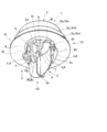
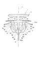
- FIG. 1 is a perspective view of a fastener according to one embodiment of the present invention
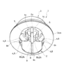
- FIG. FIG. 2 is a perspective view of the fastener viewed from the direction opposite to that of FIG. 1
- 3 is a perspective view of the fastener viewed from a direction different from that of FIGS. 1 and 2.
- FIG. FIG. 4 is a half cut side view of the fastener viewed from the direction V1 in FIG. 1 and showing the left side in cross section.
- FIG. 5 is a half-cut side view of the fastener viewed from the direction V2 in FIG. 1 and showing the left side in cross section.
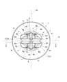
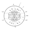
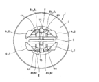
- 6 is a bottom view of the fastener as seen from the direction V3 in FIG. 1.
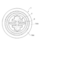
- FIG. 7 is a cross-sectional view taken along the line AA in FIG. 4.
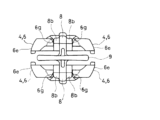
- FIG. 8 is a cross-sectional view taken along the line BB in FIG. 6.
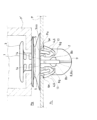
- FIG. FIG. 9 is a side view showing how the fastener is used.
- 10 is a bottom view of the fitting portion in the state of FIG. 9.
- FIG. 11 is a side view of a main part when a withdrawal force is applied from the state of FIG. 9; 12 is a bottom view of the fitting portion in the state of FIG. 11.
- FIG. 13 is a side view of the essential part when a withdrawal force greater than the state of FIG. 11 is applied.
- 14 is a bottom view of the fitting portion in the state of FIG. 13.
- FIG. 15 is a bottom view showing a partially modified example of the configuration of the fitting portion.
- FIG. 16 is a bottom view showing a partially modified example of the configuration of the fitting portion.
- FIG. 1 A typical embodiment of the present invention will be described below with reference to FIGS. 1 to 15.
- FIG. 1 The fastener 1 according to this embodiment includes a fitting portion 2 that is fitted into a through hole Pa formed in various attachment targets P (see FIGS. 9, 11 and 13). is attached to the attachment target P so as to close the . That is, the fastener 1 serves as a substitute for a shaft-like fastening member such as a rivet.
- the fastener 1 is, for example, in a state in which two mounting targets P having through holes Pa are superimposed so that the through holes Pa communicate with each other, and are fitted into the through holes Pa, whereby the two mounting targets P are attached. It can be used to fasten P.
- the fastener 1 can be used as a hole plug that is detachably fitted into the through hole Pa provided in the attachment target P when the through hole Pa is not used. More specifically, the fastener 1 can also be used as a hole closure such as a through hole Pa for mounting optional accessories such as automobiles and electric appliances.
- such a fastener 1 can be used so as to combine another object P' (see FIG. 9) with the object P attached via the fitting portion 2 by using the portion not inserted into the through hole Pa. can also
- the fastener 1 includes a head portion 3 as a non-insertion portion and a fitting portion 2. Using this head portion 3, a mounting object having a through hole Pa into which the fitting portion 2 is fitted is attached. P can be combined with another object P' (see FIG. 9).
- the head 3 is a center axis x of the fastener 1 (see FIGS. 4, 5, 6 and 8/insertion direction y of the fitting portion 2 into the through-hole Pa (see FIG. 1) of the fastener 1.
- a plurality of disk-shaped bodies 3a centered on an imaginary straight line passing through the center) are stacked in three layers with a gap between adjacent disk-shaped bodies 3a in the direction along the central axis x. It is configured in such a way that
- the disk-shaped body 3aa positioned adjacent to the base 2a of the fitting portion 2 has the largest diameter, and the remaining disk-shaped bodies 3a become smaller in diameter as they move away from this base 2a.
- a neck portion 3b is formed along the central axis x between the disk-shaped body 3ac with the smallest diameter and the intermediate disk-shaped body 3ab.
- the disk-shaped body 3aa with the largest diameter located adjacent to the base 2a of the fitting part 2 is provided with an inclination that gradually increases the distance from the intermediate disk-shaped body 3ab toward its edge. .
- the disk-shaped body 3aa having the largest diameter is elastically deformed in the direction of loosening the inclination when the fitting portion 2 is completely fitted into the through hole Pa as described later, and the insertion front side Pb of the through hole Pa is deformed. It adheres to the edge of the hole.
- the fitting portion 2 protrudes from the center of the disk-shaped body 3aa having the largest diameter along the central axis x to the side opposite to the plurality of disk-shaped bodies 3aa.
- the fitting portion 2 consists of one virtual plane (FIG. 6/hereinafter referred to as the first plane S1) including the central axis x and a virtual plane (FIG. 6/).
- the elastic piece 4 is arranged in each of the four regions divided by (hereinafter referred to as the second plane S2). Further, base portions 8 are arranged between two elastic pieces 4 on both sides of the first plane S1. Further, as shown in FIG. 2, a plate-shaped first portion 9a formed so as to extend the plate surface along the first plane S1 and a plate-like first portion 9a formed so as to intersect the first portion 9a at the position of the central axis x.
- the guide portion 9 is provided with a fin-shaped second portion 9b formed so that the plate surface is aligned with the second plane S2 formed by the second plane S2.
- the elastic pieces 4 are provided on both sides of one base portion 8 .
- the base portion 8 is provided on both sides of the guide portion 9, and the elastic pieces 4 are provided on both sides of the base portion 8 located on one side of the guide portion 9.
- the elastic pieces 4 are provided on both sides of the base portion 8 located on the other side of the .
- the elastic pieces 4 positioned on one side of the second plane S2 on both sides of the first plane S1 are substantially It is designed to have a symmetrical form.
- a gap 10 is formed between the guide portion 9, the base portion 8, and the elastic piece 4 in a direction orthogonal to the central axis x, and a gap 10 is formed between the base portion 8 and the elastic piece 4.
- a gap 11 is also formed in the direction orthogonal to the central axis x.
- the guide portion 9 is formed so that the end 9c of the guide portion 9 serves as the insertion destination Pc of the fitting portion 2 into the through hole Pa.
- the guide portion 9 is configured to have a cross shape in a cross section perpendicular to the central axis x.
- the first portion 9a has a width (dimension along the first plane S1) that is substantially equal to or slightly smaller than the hole diameter of the through hole Pa.
- the end 9c of the first portion 9a and the portion adjacent thereto are formed to follow an arc of an imaginary circle so as to facilitate introduction into the through hole Pa.
- the second portion 9b has a smaller width (dimension in the direction along the first plane S2) than the first portion 9a, and the base portion 8 is arranged with a gap between it and the projecting end 9d of the second portion 9b. .
- the end 9c of the guide portion 9 serves as the end of the fitting portion 2, and since it has a cross-shaped cross section as described above, it is difficult to deform. guided stably.
- the terminal of the base portion 8 and the bending portion 7 of the elastic piece 4 (the inner arm portion 5 described later) are positioned at the middle position of the entire length of the guide portion 9 (the length of the guide portion 9 in the insertion direction y of the through hole Pa). At the timing when the guide portion 9 is inserted into the through hole Pa to the middle of the entire length thereof, the elastic deformation of the elastic piece 4 is started.
- the base part 8 has a bar shape with one end integrally connected to the head part 3 and protruding in the direction along the central axis x.
- the portion adjacent to the base portion of the base portion 8 is integrated with the second portion 9b of the guide portion 9 via the connecting portion 12, and the base portion 8 is also configured to be difficult to deform. It has become.
- the base portion 8 is provided with an abutting portion 8b that abuts against the elastic piece 4 when a force is applied to the fastener 1 in a direction to pull out the fitting portion 2 fitted in the through hole Pa from the through hole Pa. ing.
- the contact portion 8b is configured as a protrusion 8c.
- the projections 8c are provided on both sides of the second plane S2 at positions slightly closer to the base than the end 8a of the base 8. As shown in FIG.
- the projecting portion 8c has a linear protruding end 8d along the central axis x when the fitting portion 2 is viewed from the direction facing the first plane S1 (see FIG. 6) (see FIGS. 8 and 9).
- the stepped portion 8e facing the portion adjacent to the base portion of the base portion 8 has a form with an inclination such that the projecting dimension of the projection portion 8c gradually decreases toward the portion adjacent to the base portion.
- the elastic piece 4 is located on the side of the base portion 8, and allows the insertion of the fitting portion 2 into the through hole Pa by elastic deformation in a direction approaching the base portion 8, and elastically returns at the end position of the insertion. is configured to engage with the through hole Pa at the insertion destination Pc of the insertion, and when a force f1 (see FIG. 11) is applied in a direction to extract the fitting portion 2 from the through hole Pa, the approaching configured to produce directional elastic deformation.
- the elastic piece 4 includes an inner arm portion 5 extending in the direction along the central axis x with a gap between it and the base portion 8, and this inner arm portion
- the outer arm portion 6 extends toward the base portion 2a of the fitting portion 2 from the end serving as the insertion point Pc of the fitting portion 2 into the through hole Pa.
- a gap 14 and a gap 14 are provided between the base portion 8 and the inner arm portion 5 and between the inner arm portion 5 and the outer arm portion 6, respectively. 13 are formed (see FIG. 9).
- the outer arm portion 6 has a surface 6a facing the inner arm portion 5 (see FIG. 4), a surface 6b facing the guide portion 9 (see FIG. 5), and an outer surface 6c slidingly contacting the through hole Pa during the insertion. ing.
- the outer surface 6c is curved along an arc of an imaginary circle when the fitting portion 2 is viewed from a direction orthogonal to the central axis x (see FIG. 6), and the fitting portion 2 is aligned with the through hole Pa. Fitting is made smooth.
- outer surface 6c of the outer arm 6 is inclined in a direction that gradually increases the distance from the base 8 as it approaches the head 3 side from the insertion point 7, which is the connection point with the inner arm 5.
- the outer surface 6c of the outer arm portion 6 is a three-dimensional curved surface having the aforementioned curvature and this inclination.
- the base portion 5a of the inner arm portion 5 is integrated with the base portion side of the base portion 8 via the connecting portion 14, as shown in FIG.
- the portion adjacent to the base portion 5a and the portion adjacent to the end portion 5b of the inner arm portion 5 are each configured to have a smaller cross-sectional area than the intermediate portion.
- the portion adjacent to the base portion 5a and the portion adjacent to the end 5b of the inner arm portion 5 are likely to be elastically deformed.
- the outer arm 6 has an engaging surface 6d facing the head 3 between the terminal positioned close to the head 3 and the three-dimensional curved outer surface 6c.
- the distance between the ridges 6e (engagement ends) where the engagement surface 6d and the outer surface 6c of the elastic pieces 4 formed on both sides of the base portion 8 are in contact is slightly larger than the hole diameter of the through hole Pa (see FIG. 9).
- the outer arm portion 6 positions the extending portion 6f (see FIG. 8) located between the end of the outer arm portion 6 and the engaging surface 6d within the through hole Pa. (See Figure 9).
- a force f1 is applied to the fastener 1 from the through hole Pa by the extending portion 6f in a direction to pull out the fitting portion 2, the elastic piece 4 is elastically deformed in a direction m1 toward the base portion 8. (See FIGS. 11 and 12).
- a receiving surface 6g for the linear protruding end 8d of the projection 8c is formed at a location facing the projection 8c of the base portion 8 in the vicinity of the bent portion 7 of the elastic piece 4.
- the receiving surface 6g has an inclination that gradually increases the distance from the base portion 8 as the distance from the central axis x increases.
- the contact portion 8b is the protrusion 8c.
- the contact portion 8b is formed in a flat shape, and the portion of the elastic piece 4 that abuts against the contact portion 8b is a protrusion 4a.
- the contact portion 8b is a projection 8c, and the portion of the elastic piece 4 that abuts against the contact portion 8b is a projection 4a.
- the pull-out force of the fastener 1 can be appropriately controlled by adjusting the projecting dimensions of the protrusions 8c and 4a.
- the projecting portion 4a of the elastic piece 4 is located at the portion of the contact portion 8b closer to the central axis x than the contact portion 8b.
- the protrusion 4a of the elastic piece 4 is positioned in the relief portion 15 inside the contact portion 8b. try to get in.
- the receiving surface 6g enters the portion of the abutment portion 8b that is closer, that is, the abutment state between the abutment portion 8b and the elastic piece 4 is released, and the ridge portion 6e enters the through hole Pa. 4 is elastically deformed to release the engagement between the elastic piece 4 and the through hole Pa (see FIGS. 13 and 14).
- a force f1 is applied in a direction to extract the fitting portion 2 from the through hole Pa.
- the elastic piece 4 is first elastically deformed in a direction m1 to approach the base portion 8, and then elastically deformed in a direction m2 to approach the central axis x. The engagement between the through hole Pa and the elastic piece 4 is released.
- the amount of deformation of the elastic piece 4 in the direction m1 approaching the base portion 8 and the amount of deformation of the elastic piece 4 in the direction m2 approaching the central axis x when removing the fastener 1 from the object to be fastened are Each of these elements can be minimized to prevent buckling or breakage of the elastic piece 4 during such removal, and the fastener 1 can be removed from the object to be fastened in a reusable state. It can be removed.
- the ridges 6e of the four elastic pieces 4 move from the positions shown in FIG. 12 to the center axis x as shown in FIG. is disengaged.
- the outer arm portion 6 of the elastic piece 4 is formed with a support protrusion 6h projecting toward the guide portion 9. As shown in FIG.
- the support protrusion 6h is between the engaging surface 6d and the bent portion 7 of the outer arm portion 6, and is guided from the edge portion where the surface 6b facing the guide portion 9 and the outer surface 6c meet. It protrudes toward part 9.
Landscapes
- Engineering & Computer Science (AREA)
- General Engineering & Computer Science (AREA)
- Mechanical Engineering (AREA)
- Insertion Pins And Rivets (AREA)
Abstract
Description
前記はめ込み部は、
ベース部と、
前記ベース部の側方にあって、前記貫通穴への前記はめ込み部の挿入を前記ベース部に近接する向きの弾性変形により許容すると共に、前記挿入の終了位置での弾性復帰により前記挿入の挿入先において前記貫通穴に係合するように構成され、かつ、前記貫通穴から前記はめ込み部を抜き出す向きの力が作用されたときに前記近接する向きの弾性変形を生じるように構成された弾性片とを備えており、
前記ベース部には、前記抜き出す向きの力の作用時に前記弾性片に突き当たる当接部が、設けられていると共に、
前記抜き出す向きの力が、所定の大きさ以上となったときに、前記弾性片が、前記当接部よりも内方となる前記はめ込み部の中心軸に近づく向きに撓むようにしてなる、ものとした。
これにより、かかる留め具にあっては、留め付け対象から留め具を取り外すために、貫通穴からはめ込み部を抜き出す向きの力の作用を受けると、先ず、弾性片が、ベース部に近接する向きに弾性変形し、次いで、弾性片が、中心軸に近づく向きに撓み変形し、この変形の向きを異ならせる二つの変形によって貫通穴と弾性片との係合を解除可能となる。したがって、留め付け対象から留め具を取り外すにあたっての前記ベース部に近接する向きでの弾性片の変形量、および、前記中心軸に近づく向きでの弾性片の変形量をそれぞれ、必要最小限とすることができる。このため、かかる取り外しにあたって弾性片に座屈や破断などが生じる事態を可及的に防止できる。また、再利用可能な状態での留め付け対象からの留め具の取り外しが、可能となる。
前記はめ込み部の前記挿入先側の端末を前記ガイド部の端末により構成させるようにしておくことが、この発明の態様の一つとされる。
4 弾性片
8 ベース部
8b 当接部
Pa 貫通穴
Pc 挿入先
f1 抜き出す向きの力
m1 ベース部に近接する向き
m2 中心軸に近づく向き
x はめ込み部の中心軸
なお、2021年11月12日に出願された日本国特願2021-184572号の明細書、特許請求の範囲、図面及び要約書の全内容をここに引用し、本発明の明細書の開示として、取り入れるものである。
Claims (10)
- 留め付け対象に設けられた貫通穴にはめ込まれるはめ込み部を備えてなる留め具であって、
前記はめ込み部は、
ベース部と、
前記ベース部の側方にあって、前記貫通穴への前記はめ込み部の挿入を前記ベース部に近接する向きの弾性変形により許容すると共に、前記挿入の終了位置での弾性復帰により前記挿入の挿入先において前記貫通穴に係合するように構成され、かつ、前記貫通穴から前記はめ込み部を抜き出す向きの力が作用されたときに前記近接する向きの弾性変形を生じるように構成された弾性片とを備えており、
前記ベース部には、前記抜き出す向きの力の作用時に前記弾性片に突き当たる当接部が、設けられていると共に、
前記抜き出す向きの力が、所定の大きさ以上となったときに、前記弾性片が前記当接部よりも内方となる前記はめ込み部の中心軸に近づく向きに撓むようにしてなる、留め具。 - 前記はめ込み部は、前記中心軸を含む仮想の一つの平面に沿うように形成されたガイド部を備えると共に、
前記はめ込み部の前記挿入先側の端末を前記ガイド部の端末により構成させるようにしてなる、請求項1に記載の留め具。 - 前記ガイド部は、前記仮想の一つの平面に沿った第一部分に対し、前記中心軸の位置で交叉する第二部分を備えてなる、請求項2に記載の留め具。
- 前記弾性片を、前記ベース部との間に間隔を開けて前記中心軸に沿う向きに延びる内腕部と、この内腕部の前記挿入先側の端末から前記はめ込み部の基部側に延びる外腕部とを備えた屈曲片状としてなる、請求項1乃至請求項3のいずれか1項に記載の留め具。
- 前記抜き出す向きの力の作用時に、前記弾性片の前記内腕部の前記挿入先側の端末が、前記ベース部の前記当接部に突き当たるように構成される、請求項4に記載の留め具。
- 前記弾性片の前記外腕部に前記ガイド部側に突き出す支持突部を形成させてなる、請求項5に記載の留め具。
- 前記当接部及び前記弾性片における前記当接部に突き当たる箇所の双方又はいずれか一方を、突部とさせてなる、請求項1乃至請求項6のいずれか1項に記載の留め具。
- 一つの前記ベース部の両側にそれぞれ前記弾性片を備えさせなる、請求項1乃至請求項7のいずれか1項に記載の留め具。
- 前記ガイド部の両側にそれぞれ前記ベース部を備えさせると共に、前記ガイド部の第1側に位置するベース部の両側にそれぞれ前記弾性片を備えさせ、かつ、前記ガイド部の第2側に位置するベース部の両側にそれぞれ前記弾性片を備えさせてなる、請求項2乃至請求項8のいずれか1項に記載の留め具。
- 前記弾性片の前記外腕部における前記はめ込み部の基部に隣接して位置される前記貫通穴に対する係合端と前記中心軸との距離が、四つの前記弾性片においてそれぞれ等しくなるようにしてなる、請求項9に記載の留め具。
Priority Applications (3)
| Application Number | Priority Date | Filing Date | Title |
|---|---|---|---|
| US18/696,201 US12595817B2 (en) | 2021-11-12 | 2022-10-28 | Fastener |
| CN202280072572.3A CN118251551A (zh) | 2021-11-12 | 2022-10-28 | 紧固件 |
| DE112022004066.1T DE112022004066T5 (de) | 2021-11-12 | 2022-10-28 | Befestigungselement |
Applications Claiming Priority (2)
| Application Number | Priority Date | Filing Date | Title |
|---|---|---|---|
| JP2021184572A JP7542509B2 (ja) | 2021-11-12 | 2021-11-12 | 留め具 |
| JP2021-184572 | 2021-11-12 |
Publications (1)
| Publication Number | Publication Date |
|---|---|
| WO2023085122A1 true WO2023085122A1 (ja) | 2023-05-19 |
Family
ID=86335696
Family Applications (1)
| Application Number | Title | Priority Date | Filing Date |
|---|---|---|---|
| PCT/JP2022/040358 Ceased WO2023085122A1 (ja) | 2021-11-12 | 2022-10-28 | 留め具 |
Country Status (5)
| Country | Link |
|---|---|
| US (1) | US12595817B2 (ja) |
| JP (1) | JP7542509B2 (ja) |
| CN (1) | CN118251551A (ja) |
| DE (1) | DE112022004066T5 (ja) |
| WO (1) | WO2023085122A1 (ja) |
Citations (4)
| Publication number | Priority date | Publication date | Assignee | Title |
|---|---|---|---|---|
| JPS60196013U (ja) * | 1984-06-04 | 1985-12-27 | 株式会社 ニフコ | プラスチツク製アンカ−形クリツプ |
| JP2000055021A (ja) * | 1998-08-11 | 2000-02-22 | Piolax Inc | 部品取付け用クリップ |
| WO2009093496A1 (ja) * | 2008-01-22 | 2009-07-30 | Piolax Inc. | クリップ |
| JP2014009743A (ja) * | 2012-06-29 | 2014-01-20 | Nifco Inc | クリップ |
Family Cites Families (3)
| Publication number | Priority date | Publication date | Assignee | Title |
|---|---|---|---|---|
| JP5558322B2 (ja) | 2010-11-25 | 2014-07-23 | 大和化成工業株式会社 | クリップ |
| JP2017115978A (ja) * | 2015-12-24 | 2017-06-29 | 大和化成工業株式会社 | クリップ |
| JP2021184572A (ja) | 2020-05-22 | 2021-12-02 | 正男 山本 | 無反射像撮影用のカメラ用アクセサリ |
-
2021
- 2021-11-12 JP JP2021184572A patent/JP7542509B2/ja active Active
-
2022
- 2022-10-28 US US18/696,201 patent/US12595817B2/en active Active
- 2022-10-28 CN CN202280072572.3A patent/CN118251551A/zh active Pending
- 2022-10-28 WO PCT/JP2022/040358 patent/WO2023085122A1/ja not_active Ceased
- 2022-10-28 DE DE112022004066.1T patent/DE112022004066T5/de active Pending
Patent Citations (4)
| Publication number | Priority date | Publication date | Assignee | Title |
|---|---|---|---|---|
| JPS60196013U (ja) * | 1984-06-04 | 1985-12-27 | 株式会社 ニフコ | プラスチツク製アンカ−形クリツプ |
| JP2000055021A (ja) * | 1998-08-11 | 2000-02-22 | Piolax Inc | 部品取付け用クリップ |
| WO2009093496A1 (ja) * | 2008-01-22 | 2009-07-30 | Piolax Inc. | クリップ |
| JP2014009743A (ja) * | 2012-06-29 | 2014-01-20 | Nifco Inc | クリップ |
Also Published As
| Publication number | Publication date |
|---|---|
| JP7542509B2 (ja) | 2024-08-30 |
| JP2023072189A (ja) | 2023-05-24 |
| US12595817B2 (en) | 2026-04-07 |
| DE112022004066T5 (de) | 2024-05-29 |
| CN118251551A (zh) | 2024-06-25 |
| US20240401628A1 (en) | 2024-12-05 |
Similar Documents
| Publication | Publication Date | Title |
|---|---|---|
| US6691380B2 (en) | Fasteners of increased holding power | |
| JP2719006B2 (ja) | プッシュインファスナ | |
| JP5666400B2 (ja) | クリップ | |
| JP5627940B2 (ja) | グロメット | |
| EP0248591A2 (en) | Resilient clip | |
| JP6255033B2 (ja) | 止め具 | |
| US9956925B2 (en) | Attaching structure assembly for an attached component | |
| JP2004156722A (ja) | 本留め用の雄パーツを有する連結具 | |
| CN107614897A (zh) | 紧固部件和用于形成紧固部件的方法 | |
| CN105556139B (zh) | 卡夹 | |
| CN113163904B (zh) | 带扣用的插头及带扣 | |
| EP2778442B1 (en) | Fastening method and apparatus | |
| WO2023085122A1 (ja) | 留め具 | |
| WO2017199842A1 (ja) | クリップ | |
| JP2013232618A (ja) | ケーブル保持具 | |
| JP3130203B2 (ja) | バックル | |
| CN107084177B (zh) | 紧固件及部件安装构造 | |
| JP2011027214A (ja) | 留め具 | |
| JPH0724105U (ja) | バックル | |
| JP3210712U (ja) | 連結具 | |
| US20250188968A1 (en) | Clip | |
| CN113871941B (zh) | 卡扣、连接器及车辆 | |
| JP2013104537A (ja) | 取付具 | |
| JP7214551B2 (ja) | 留め具取付構造および留め具 | |
| JP7134363B2 (ja) | サンバイザホルダ |
Legal Events
| Date | Code | Title | Description |
|---|---|---|---|
| 121 | Ep: the epo has been informed by wipo that ep was designated in this application |
Ref document number: 22892621 Country of ref document: EP Kind code of ref document: A1 |
|
| WWE | Wipo information: entry into national phase |
Ref document number: 202417029273 Country of ref document: IN |
|
| WWE | Wipo information: entry into national phase |
Ref document number: 202280072572.3 Country of ref document: CN |
|
| WWE | Wipo information: entry into national phase |
Ref document number: 2401002969 Country of ref document: TH |
|
| 122 | Ep: pct application non-entry in european phase |
Ref document number: 22892621 Country of ref document: EP Kind code of ref document: A1 |
|
| WWG | Wipo information: grant in national office |
Ref document number: 18696201 Country of ref document: US |