WO2023084584A1 - めっき装置 - Google Patents
めっき装置 Download PDFInfo
- Publication number
- WO2023084584A1 WO2023084584A1 PCT/JP2021/041137 JP2021041137W WO2023084584A1 WO 2023084584 A1 WO2023084584 A1 WO 2023084584A1 JP 2021041137 W JP2021041137 W JP 2021041137W WO 2023084584 A1 WO2023084584 A1 WO 2023084584A1
- Authority
- WO
- WIPO (PCT)
- Prior art keywords
- substrate
- plated
- back plate
- peeling
- plating
- Prior art date
- Legal status (The legal status is an assumption and is not a legal conclusion. Google has not performed a legal analysis and makes no representation as to the accuracy of the status listed.)
- Ceased
Links
Images





Classifications
-
- C—CHEMISTRY; METALLURGY
- C25—ELECTROLYTIC OR ELECTROPHORETIC PROCESSES; APPARATUS THEREFOR
- C25D—PROCESSES FOR THE ELECTROLYTIC OR ELECTROPHORETIC PRODUCTION OF COATINGS; ELECTROFORMING; APPARATUS THEREFOR
- C25D17/00—Constructional parts, or assemblies thereof, of cells for electrolytic coating
- C25D17/06—Suspending or supporting devices for articles to be coated
-
- C—CHEMISTRY; METALLURGY
- C25—ELECTROLYTIC OR ELECTROPHORETIC PROCESSES; APPARATUS THEREFOR
- C25D—PROCESSES FOR THE ELECTROLYTIC OR ELECTROPHORETIC PRODUCTION OF COATINGS; ELECTROFORMING; APPARATUS THEREFOR
- C25D17/00—Constructional parts, or assemblies thereof, of cells for electrolytic coating
-
- C—CHEMISTRY; METALLURGY
- C25—ELECTROLYTIC OR ELECTROPHORETIC PROCESSES; APPARATUS THEREFOR
- C25D—PROCESSES FOR THE ELECTROLYTIC OR ELECTROPHORETIC PRODUCTION OF COATINGS; ELECTROFORMING; APPARATUS THEREFOR
- C25D17/00—Constructional parts, or assemblies thereof, of cells for electrolytic coating
- C25D17/001—Apparatus specially adapted for electrolytic coating of wafers, e.g. semiconductors or solar cells
-
- C—CHEMISTRY; METALLURGY
- C25—ELECTROLYTIC OR ELECTROPHORETIC PROCESSES; APPARATUS THEREFOR
- C25D—PROCESSES FOR THE ELECTROLYTIC OR ELECTROPHORETIC PRODUCTION OF COATINGS; ELECTROFORMING; APPARATUS THEREFOR
- C25D17/00—Constructional parts, or assemblies thereof, of cells for electrolytic coating
- C25D17/10—Electrodes, e.g. composition, counter electrode
- C25D17/12—Shape or form
-
- C—CHEMISTRY; METALLURGY
- C25—ELECTROLYTIC OR ELECTROPHORETIC PROCESSES; APPARATUS THEREFOR
- C25D—PROCESSES FOR THE ELECTROLYTIC OR ELECTROPHORETIC PRODUCTION OF COATINGS; ELECTROFORMING; APPARATUS THEREFOR
- C25D21/00—Processes for servicing or operating cells for electrolytic coating
- C25D21/10—Agitating of electrolytes; Moving of racks
-
- C—CHEMISTRY; METALLURGY
- C25—ELECTROLYTIC OR ELECTROPHORETIC PROCESSES; APPARATUS THEREFOR
- C25D—PROCESSES FOR THE ELECTROLYTIC OR ELECTROPHORETIC PRODUCTION OF COATINGS; ELECTROFORMING; APPARATUS THEREFOR
- C25D5/00—Electroplating characterised by the process; Pretreatment or after-treatment of workpieces
- C25D5/02—Electroplating of selected surface areas
-
- C—CHEMISTRY; METALLURGY
- C25—ELECTROLYTIC OR ELECTROPHORETIC PROCESSES; APPARATUS THEREFOR
- C25D—PROCESSES FOR THE ELECTROLYTIC OR ELECTROPHORETIC PRODUCTION OF COATINGS; ELECTROFORMING; APPARATUS THEREFOR
- C25D7/00—Electroplating characterised by the article coated
- C25D7/12—Semiconductors
Definitions
- This application relates to plating equipment.
- a cup-type electroplating device is known as an example of a plating device.
- a cup-type electroplating apparatus immerses a substrate (for example, a semiconductor wafer) held in a substrate holder with the surface to be plated facing downward in a plating solution, and applies a voltage between the substrate and the anode to A conductive film is deposited on the surface of the substrate.
- Patent Document 1 discloses a substrate holder that includes a ring-shaped support member that supports the outer peripheral portion of the surface to be plated of the substrate, and a back plate assembly that is arranged on the back side of the surface to be plated of the substrate. ing.
- This substrate holder is configured to hold the substrate between the support member and the back plate assembly by pressing the back plate assembly against the back surface of the substrate to be plated supported by the support member.
- the conventional substrate holder has room for improvement in terms of preventing the substrate from sticking to the back plate assembly.
- the substrate in the conventional technology, if the substrate is placed on the substrate holder while the front and back surfaces of the substrate are wet due to pre-plating treatment, etc., sticking may occur between the substrate and the back plate assembly due to surface tension. . In this case, when the back plate assembly is lifted after the plating process is finished, the substrate may be lifted while sticking to the back plate assembly, resulting in defective transport of the substrate.
- one object of the present application is to prevent the board from sticking to the back plate assembly.
- a plating bath configured to contain a plating solution, a substrate holder configured to hold a substrate with a surface to be plated facing downward, and a substrate holder configured to move up and down a lifting mechanism configured to support the substrate holder, wherein the substrate holder includes a support mechanism configured to support the outer peripheral portion of the surface to be plated of the substrate; a back plate assembly configured to sandwich the substrate together with a support mechanism; a peeling mechanism configured to apply a force for peeling the substrate from the back plate assembly to the back surface of the plated surface of the substrate;
- a plating apparatus comprising:
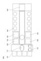
- FIG. 1 is a perspective view showing the overall configuration of the plating apparatus of this embodiment.
- FIG. 2 is a plan view showing the overall configuration of the plating apparatus of this embodiment.
- FIG. 3 is a longitudinal sectional view schematically showing the configuration of the plating module of this embodiment.
- FIG. 4 is a perspective view schematically showing the configuration of the substrate holder of this embodiment.
- FIG. 5 is a schematic enlarged perspective view of a part of the substrate holder of the present embodiment.
- FIG. 6 is a schematic enlarged perspective view of a part of the substrate holder of the present embodiment.
- FIG. 7 is a plan view schematically showing the substrate holder of this embodiment.
- FIG. 8 is a schematic enlarged perspective view of a part of the substrate holder of the modification.
- FIG. 9 is a schematic enlarged perspective view of a part of the substrate holder of the modification.
- FIG. 1 is a perspective view showing the overall configuration of the plating apparatus of this embodiment.
- FIG. 2 is a plan view showing the overall configuration of the plating apparatus of this embodiment.
- the plating apparatus 1000 includes a load port 100, a transfer robot 110, an aligner 120, a pre-wet module 200, a pre-soak module 300, a plating module 400, a cleaning module 500, a spin rinse dryer 600, and a transfer device. 700 and a control module 800 .
- the load port 100 is a module for loading substrates stored in cassettes such as FOUPs (not shown) into the plating apparatus 1000 and for unloading substrates from the plating apparatus 1000 to cassettes. Although four load ports 100 are arranged horizontally in this embodiment, the number and arrangement of the load ports 100 are arbitrary.
- the transfer robot 110 is a robot for transferring substrates, and is configured to transfer substrates between the load port 100 , the aligner 120 , the pre-wet module 200 and the spin rinse dryer 60 . When transferring substrates between the transfer robot 110 and the transfer device 700, the transfer robot 110 and the transfer device 700 can transfer the substrates via a temporary placement table (not shown).
- the aligner 120 is a module for aligning the positions of orientation flats, notches, etc. of the substrate in a predetermined direction. Although two aligners 120 are arranged horizontally in this embodiment, the number and arrangement of the aligners 120 are arbitrary.
- the pre-wet module 200 replaces the air inside the pattern formed on the substrate surface with the treatment liquid by wetting the surface to be plated of the substrate before the plating treatment with a treatment liquid such as pure water or degassed water.
- the pre-wet module 200 is configured to perform a pre-wet process that facilitates the supply of the plating solution to the inside of the pattern by replacing the treatment solution inside the pattern with the plating solution during plating. Although two pre-wet modules 200 are arranged vertically in this embodiment, the number and arrangement of the pre-wet modules 200 are arbitrary.
- the presoak module 300 for example, an oxide film having a large electrical resistance existing on the surface of a seed layer formed on the surface to be plated of the substrate before plating is removed by etching with a treatment liquid such as sulfuric acid or hydrochloric acid, and the surface of the plating substrate is cleaned.
- a treatment liquid such as sulfuric acid or hydrochloric acid
- it is configured to perform a pre-soak process for activation.
- two presoak modules 300 are arranged side by side in the vertical direction, but the number and arrangement of the presoak modules 300 are arbitrary.
- the plating module 400 applies plating to the substrate. In this embodiment, there are two sets of 12 plating modules 400 arranged vertically and four horizontally, and a total of 24 plating modules 400 are provided. The number and arrangement of are arbitrary.
- the cleaning module 500 is configured to perform a cleaning process on the substrate in order to remove the plating solution and the like remaining on the substrate after the plating process.
- the spin rinse dryer 600 is a module for drying the substrate after cleaning by rotating it at high speed. Although two spin rinse dryers are arranged vertically in this embodiment, the number and arrangement of the spin rinse dryers are arbitrary.
- the transport device 700 is a device for transporting substrates between a plurality of modules within the plating apparatus 1000 .
- Control module 800 is configured to control a plurality of modules of plating apparatus 1000 and may comprise, for example, a general purpose or dedicated computer with input/output interfaces to an operator.
- a substrate stored in a cassette is loaded into the load port 100 .
- the transport robot 110 takes out the substrate from the cassette of the load port 100 and transports the substrate to the aligner 120 .
- the aligner 120 aligns orientation flats, notches, etc. of the substrate in a predetermined direction.
- the transfer robot 110 transfers the substrates aligned by the aligner 120 to the pre-wet module 200 .
- the pre-wet module 200 pre-wets the substrate.
- the transport device 700 transports the pre-wet processed substrate to the pre-soak module 300 .
- the presoak module 300 applies a presoak treatment to the substrate.
- the transport device 700 transports the presoaked substrate to the plating module 400 .
- the plating module 400 applies plating to the substrate.
- the transport device 700 transports the plated substrate to the cleaning module 500 .
- the cleaning module 500 performs a cleaning process on the substrate.
- the transport device 700 transports the cleaned substrate to the spin rinse dryer 600 .
- a spin rinse dryer 600 performs a drying process on the substrate.
- the transport robot 110 receives the substrate from the spin rinse dryer 600 and transports the dried substrate to the cassette of the load port 100 . Finally, the cassette containing the substrates is unloaded from the load port 100 .
- FIG. 3 is a longitudinal sectional view schematically showing the configuration of the plating module 400 of the first embodiment.
- plating module 400 includes a plating bath 410 for containing a plating solution.
- the plating module 400 includes a membrane 420 that vertically separates the interior of the plating bath 410 .
- the interior of the plating bath 410 is partitioned into a cathode area 422 and an anode area 424 by a membrane 420 .
- Cathode region 422 and anode region 424 are each filled with a plating solution.
- An anode 430 is provided on the bottom surface of the plating bath 410 in the anode area 424 .
- a resistor 450 is disposed in the cathode region 422 so as to face the membrane 420 .
- the resistor 450 is a member for uniformizing the plating process on the surface to be plated Wf-a of the substrate Wf, and is composed of a plate-like member having a large number of holes.
- the plating module 400 also includes a substrate holder 440 for holding the substrate Wf with the surface to be plated Wf-a facing downward.
- the substrate holder 440 includes power contacts for powering the substrate Wf from a power source (not shown).
- the plating module 400 includes an elevating mechanism 442 for elevating the substrate holder 440 .
- the lifting mechanism 442 can be implemented by a known mechanism such as a motor.
- the plating module 400 uses the elevating mechanism 442 to immerse the substrate Wf in the plating solution in the cathode region 422, and applies a voltage between the anode 430 and the substrate Wf, thereby causing the surface Wf-a of the substrate Wf to be plated. Configured for plating.
- the plating module 400 also includes a rotation mechanism 446 for rotating the substrate holder 440 so that the substrate Wf rotates around a virtual rotation axis extending vertically through the center of the surface to be plated Wf-a.
- the rotating mechanism 446 can be implemented by a known mechanism such as a motor.
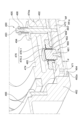
- FIG. 4 is a perspective view schematically showing the configuration of the substrate holder of this embodiment.
- FIG. 5 is a schematic enlarged perspective view of a part of the substrate holder of the present embodiment.
- the substrate holder 440 includes a support mechanism 460 for supporting the outer peripheral portion of the surface to be plated Wf-a of the substrate Wf, a back plate assembly 470 for holding the substrate Wf, and a rotating shaft 448 extending vertically upward from the back plate assembly 470 .
- the back plate assembly 470 includes a disc-shaped floating plate 472 for sandwiching the substrate Wf together with the support mechanism 460 .
- the floating plate 472 is arranged on the back side of the surface to be plated Wf-a of the substrate Wf.
- the back plate assembly 470 also includes a floating mechanism 490 for urging the floating plate 472 away from the back surface of the substrate Wf, and a floating plate 472 that presses the floating plate 472 against the back surface of the substrate Wf against the urging force of the floating mechanism 490. and a pressing mechanism 480 for pressing.
- the pressing mechanism 480 includes a disc-shaped back plate 474 arranged above the floating plate 472 and a channel 476 formed inside the back plate 474 .
- the flow path 476 includes a first flow path 476-1 radially extending from the central portion of the back plate 474 toward the outer peripheral portion, and a vertical flow path opening from the first flow path 476-1 to the lower surface of the back plate 474. and a second channel 476-2 extending in the direction of
- the pressing mechanism 480 comprises a diaphragm 484 located in the second flow path 476-2.
- the diaphragm 484 is a thin film member.
- the outer peripheral portion of diaphragm 484 is fixed to the lower surface of back plate 474 by fixing member 483 .
- the pressing mechanism 480 includes a rod 482 as one aspect of the pressing member arranged between the diaphragm 484 and the floating plate 472 .
- the bottom surface of the rod 482 is fixed to the floating plate 472 by bolts 481 , and the top surface of the rod 482 is in contact with the bottom surface of the diaphragm 484 .
- a cap 485 is placed on the top of the rod 482 with a diaphragm 484 interposed therebetween.
- the central portion of diaphragm 484 is sandwiched between cap 485 and rod 482 .
- a plurality of diaphragms 484 , rods 482 and caps 485 are provided along the circumferential direction of back plate assembly 470 .
- the rod 482 which is a separate member from the floating plate 472, is fixed to the upper surface of the floating plate 472.
- the present invention is not limited to this. may be formed.
- the protrusion functions as a pressing member similar to the rod 482 .
- the pressing mechanism 480 includes a fluid source 488 for supplying fluid to the diaphragm 484 .
- the fluid may be gas such as air or liquid such as water.
- a channel 449 extending in the vertical direction is formed in the rotary shaft 448 , and the fluid source 488 is connected to the upper end of the channel 449 .
- the lower end of channel 449 is connected to first channel 476 - 1 formed in back plate 474 .
- the first channel 476-1 radially extends from the center of the back plate 474 and communicates with the upper surface of the cap 485 via the second channel 476-2.
- Fluid source 488 supplies fluid to diaphragm 484 via channel 449 and channel 476 . Then, the cap 485 and the rod 482 are pushed downward, thereby pushing the floating plate 472 downward.
- the support mechanism 460 includes an annular support member 462 for supporting the outer periphery of the plating surface Wf-a of the substrate Wf.
- the support member 462 has a flange 462 a protruding from the outer periphery of the lower surface of the back plate assembly 470 .
- An annular seal member 464 is positioned over the flange 462a.
- the sealing member 464 is a member having elasticity.
- the supporting member 462 supports the peripheral portion of the surface to be plated Wf-a of the substrate Wf through the sealing member 464 . By sandwiching the substrate Wf between the sealing member 464 and the floating plate 472, the space between the supporting member 462 and the substrate Wf is sealed. Since the seal member 464 has elasticity, it is crushed according to the pressing force of the substrate Wf by the pressing mechanism 480 and the thickness ⁇ changes.
- the support mechanism 460 includes an annular clamper 466 held by a support member 462 .
- the clamper 466 can move the back plate assembly 470 up and down with respect to the support mechanism 460 when placing/removing the substrate Wf on/from the substrate holder 440 . Also, the clamper 466 can restrict the back plate 474 from moving upward (away from the back surface of the substrate Wf) when the fluid is supplied from the fluid source 488 to the diaphragm 484 . This point will be described below.
- the back plate assembly 470 includes a slide ring 478 provided annularly on the outer periphery of the upper surface of the back plate 474 .
- the slide ring 478 is circumferentially movable independently of the back plate 474 .
- Back plate assembly 470 includes slide plate 479 protruding from slide ring 478 toward clamper 466 .
- the clamper 466 has a hook-shaped notch 466 d formed on the surface facing the slide ring 478 .
- the hook-shaped notch 466d has a first groove 466a extending vertically so that the slide plate 479 can move up and down, and a second groove 466a extending along the circumferential direction of the clamper 466 in communication with the first groove 466a. and a groove 466b of .
- On the upper surface of the second groove 466b there is a contact surface 466c that contacts the upper surface of the slide plate 479 that moves as the back plate 474 moves upward when fluid is supplied from the fluid source 488 to the diaphragm 484. It is formed.
- a plurality of slide plates 479 and notches 466 d are provided along the circumferential direction of substrate holder 440 .
- the back plate assembly 470 is positioned above the support mechanism 460 when the substrate Wf is placed on the substrate holder 440 .
- the back plate assembly 470 can be lowered with respect to the support mechanism 460 by aligning the circumferential position of the slide plate 479 with the first groove 466a. can.
- the slide ring 478 is rotated in the circumferential direction to fit the slide plate 479 into the second groove 466b.
- the slide plate 479 and the contact surface 466c face each other, so that the upward movement of the back plate assembly 470 is restricted.
- the floating mechanism 490 includes a shaft 492 extending upward from the floating plate 472 through the through hole 474a of the back plate 474.
- the lower end of shaft 492 is fixed to floating plate 472 .
- Floating mechanism 490 includes a flange 495 attached to shaft 492 above backplate 474 .
- Flange 495 is attached to the upper end of shaft 492 by bolts 493 .
- the floating mechanism 490 includes a guide 494 provided in the through hole 474a.
- the guide 494 has a hole slightly larger than the outer diameter of the shaft 492 and is attached to the upper end of the through hole 474a.
- the guide 494 is configured to guide the vertical movement of the shaft 492 . By providing the guide 494 , it is possible to suppress the occurrence of radial positional deviation between the floating plate 472 and the back plate 474 .
- the floating mechanism 490 includes a compression spring 496 attached to the upper surface of the guide 494 and the lower surface of the flange 495 .
- a compression spring 496 may be provided between the upper surface of the backplate 474 and the lower surface of the flange 495 . Since the compression spring 496 has an urging force that lifts the flange 495 upward, the floating plate 472 is urged away from the back surface of the substrate Wf via the shaft 492 .
- the pressing mechanism 480 presses the substrate Wf against the sealing member 464 with a force stronger than the urging force of the floating mechanism 490 .
- the pressing mechanism 480 can change the holding position of the substrate Wf according to the pressure of the fluid supplied from the fluid source 488 .
- the amount of compression of the seal member 464 increases. Reducing the thickness of the seal member 464 means that the holding position of the substrate Wf moves downward, so that the distance between the anode 430 and the substrate Wf becomes shorter. That is, by adjusting the flow rate of the fluid supplied from the fluid source 488, the distance between the anode 430 and the substrate Wf can be adjusted. Therefore, according to the present embodiment, by adjusting the distance between the anode 430 and the substrate Wf according to the type of the substrate Wf, the uniformity of the plating film thickness on the surface to be plated Wf-a can be improved. can. Further, as shown in FIG.
- the substrate holder 440 includes a peeling mechanism 471 configured to apply a force for peeling the substrate Wf from the back plate assembly 470 to the back surface of the plated surface Wf-a of the substrate Wf. . Details of the peeling mechanism 471 will be described below.
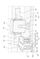
- FIG. 6 is a schematic enlarged perspective view of a part of the substrate holder of the present embodiment.
- the substrate holder 440 includes a pedestal 467 supported by the support mechanism 460 and contacts 496 attached to the pedestal 467 .
- the pedestal 467 is, for example, an annular member having conductivity such as stainless steel.
- the contact 496 is a conductive member attached to the inner peripheral surface of the pedestal 467 with a screw or the like, and is electrically connected to a power source (not shown).
- a plurality of contacts 496 are arranged along the inner peripheral surface of base 467 .
- the contact 469 is formed with a plurality of feed contacts 469-a.
- a plurality of power supply contacts 469-a are brought into contact with the outer peripheral portion of the surface to be plated Wf-a of the substrate Wf, thereby supplying power to the substrate Wf.
- the peeling mechanism 471 is arranged in a hole 473 that opens in the surface (specifically, the lower surface of the floating plate 472) of the back plate assembly 470 that contacts the back surface of the plated surface Wf-a of the substrate Wf. It includes a stripping member 475 that has been sealed.
- the hole 473 is a through hole penetrating through the lower surface and the upper surface of the floating plate 472 .
- the upper opening of the hole 473 is closed by a plate-like pedestal 486 .
- the pedestal 486 is fixed to the floating plate 472 with bolts 487 .
- the holes 473 include a first hole 473-a which opens in the lower surface of the floating plate 472 and has a first diameter, and a first hole 473-a which has a second diameter larger than the first diameter. and a second hole 473-b communicating with a.
- the peeling member 475 includes a peeling pin 475-a having a size corresponding to the first diameter, and a flange portion 475-b having a size corresponding to the second diameter is formed on the peeling pin 475-a. It is The tip portion of the peeling pin 475-a that contacts the substrate Wf is formed in a hemispherical shape.
- the peeling member 475 can be made of resin such as PVC, PP, PPS, PEEK, or PTFE, or antistatic grade resin.
- the peeling mechanism 471 includes an elastic member 477 that imparts a force that causes the peeling member 475 to protrude from the lower surface of the floating plate 472 .
- the elastic member 477 can be configured by, for example, a compression spring.
- the elastic member 477 is inserted into a hole formed in the central portion of the proximal end of the peeling pin 475-a and attached to the bottom surface of the hole and the pedestal 486. As shown in FIG.
- sticking of the substrate Wf to the back plate assembly 470 can be suppressed. That is, if the substrate Wf is placed on the substrate holder 440 while the front and back surfaces of the substrate Wf are wet due to pre-plating treatment, etc., sticking may occur between the substrate Wf and the back plate assembly 470 due to surface tension. . In this case, when the back plate assembly 470 is lifted after the plating process is completed, the substrate Wf may be lifted while sticking to the back plate assembly 470, and as a result, the substrate may be transported incorrectly.
- FIG. 7 is a plan view schematically showing the substrate holder of this embodiment.
- a plurality (six in this embodiment) of the peeling mechanisms 471 are provided along the circumferential direction on the outer peripheral portion of the floating plate 472 .
- the peeling mechanism 471 By arranging the peeling mechanism 471 on the outer periphery of the floating plate 472, it becomes easier for air to enter between the substrate Wf and the floating plate 472, so that sticking of the substrate Wf due to surface tension can be efficiently suppressed. .
- sticking of the substrate Wf to the back plate assembly 470 can be more reliably suppressed.
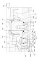
- FIG. 8 is a schematic enlarged perspective view of a part of the substrate holder of the modified example.
- the peeling mechanism 471 includes a peeling member 475 arranged in a hole 473 similar to that of the above embodiment, and a fluid that imparts a force that causes the peeling member 475 to protrude from the lower surface of the back plate assembly 470 (lower surface of the floating plate 472). and a fluid source 488 for supplying.
- the peeling member 475 includes a peeling pin 475-a having a size corresponding to the first diameter of the first hole 473-a, and the peeling pin 475-a has a size corresponding to the second diameter.
- no hole is formed in the central portion of the proximal end of the peeling pin 475-a.
- a space 491 between the peeling member 475 and the pedestal 486 communicates with the channel 476 via a channel 497 formed in the cap 485 , the rod 482 and the floating plate 472 . This allows the fluid supplied from the fluid source 488 to be guided to the space 491 .
- an O-ring 461 is interposed between the lower surface of the rod 482 and the upper surface of the floating plate 472 to prevent fluid leakage.
- An O-ring 489 is interposed between the side surface of the flange portion 475-b of the peeling member 475 and the side surface of the second hole 473-b to prevent fluid leakage.
- the peeling member 475 moves downward until the flange portion 475-b of the peeling pin 475-a contacts the step between the first hole 473-a and the second hole 473-b. As a result, the peeling member 475 protrudes from the hole 473 (opening on the lower surface of the floating plate 472). As a result, the peeling member 475 presses the substrate Wf to separate it from the back plate assembly 470 , so that the substrate Wf can be prevented from sticking to the back plate assembly 470 .
- FIG. 9 is a schematic enlarged perspective view of a part of the substrate holder of the modified example.
- the peeling mechanism 471 has a hole 465 that opens to the surface of the back plate assembly 470 that contacts the back surface of the surface to be plated Wf-a of the substrate Wf. and a fluid source 488 configured to supply a.
- the holes 465 include a first hole 465-a that opens in the lower surface of the floating plate 472 and has a first diameter, and a first hole 465-a that has a second diameter larger than the first diameter. and a communicating second hole 465-b.
- Hole 465 (second hole 465 - b ) communicates with channel 476 through channel 497 formed in cap 485 , rod 482 and floating plate 472 . Thereby, the fluid supplied from the fluid source 488 is guided to the hole 465 (second hole 465-b). Since the flow path 497 is formed in the rod 482 and the floating plate 472, an O-ring 461 is interposed between the lower surface of the rod 482 and the upper surface of the floating plate 472 to prevent fluid leakage. There is An O-ring 463 is interposed between the lower surface of the floating plate 472 and the upper surface of the substrate Wf to prevent fluid leakage.
- the biasing force of the floating mechanism 490 becomes greater than the pressing force of the pressing mechanism 480, and the back plate assembly 470 rises.
- the gas is still supplied from the fluid source 488 to the hole 465, the gas is supplied to the upper surface of the substrate Wf from the first hole 465-a.
- the gas presses the substrate Wf and separates it from the back plate assembly 470, so that sticking of the substrate Wf to the back plate assembly 470 can be suppressed.
- the present application provides, as one embodiment, a plating bath configured to contain a plating solution, a substrate holder configured to hold a substrate with the surface to be plated facing downward, and a substrate holder configured to move up and down.
- a lifting mechanism configured to: a support mechanism configured to support the outer peripheral portion of the surface to be plated of the substrate; and a support mechanism configured to support the outer peripheral portion of the surface to be plated of the substrate; a back plate assembly configured to sandwich the substrate together with the support mechanism; and a peeling mechanism configured to apply a force for peeling the substrate from the back plate assembly to the back surface of the plated surface of the substrate.
- a plating apparatus is disclosed, comprising:
- the peeling mechanism includes a peeling member arranged in a hole that is open to a surface of the back plate assembly that contacts the back surface of the substrate to be plated, and the peeling member. and an elastic member that imparts a force to protrude from the lower surface of the back plate assembly.
- the peeling mechanism includes a peeling member arranged in a hole that is open to a surface of the back plate assembly that contacts the back surface of the substrate to be plated, and the peeling member. and a fluid source for supplying a fluid that imparts a force to protrude from the lower surface of the back plate assembly.
- the peeling mechanism supplies a gas to the back surface of the substrate to be plated through a hole opened in a surface of the back plate assembly that contacts the back surface of the substrate to be plated.
- a plating apparatus is disclosed that includes a fluid source configured to supply.
- the present application discloses, as one embodiment, a plating apparatus in which a plurality of the peeling mechanisms are provided along the circumferential direction on the outer peripheral portion of the back plate assembly.
- the back plate assembly includes a floating plate arranged on the back surface side of the surface to be plated of the substrate, and a floating plate for urging the floating plate away from the back surface of the substrate. a floating mechanism; and a pressing mechanism for pressing the floating plate against the back surface of the substrate against the biasing force of the floating mechanism.
- a plating apparatus is disclosed that is configured to apply to the back surface of the surface to be plated of the substrate.
- the pressing mechanism includes a back plate arranged above the floating plate, and a channel formed inside the back plate so as to open to the lower surface of the back plate. a diaphragm arranged in the flow channel, a pressing member arranged between the diaphragm and the floating plate, and a fluid source for supplying fluid to the diaphragm through the flow channel; A plating apparatus is disclosed.
- the floating mechanism includes a shaft extending upward from the floating plate through a through hole of the back plate, a flange attached to the shaft above the back plate, and the A plating apparatus is disclosed that includes a top surface of a backplate and a spring member attached to the flange.
- plating module 410 plating bath 440 substrate holder 442 lifting mechanism 460 support mechanism 462 support member 470 back plate assembly 471 peeling mechanism 472 floating plate 473 hole 473-a first hole 473-b second hole 474 back plate 475 for peeling Member 475-a Peeling pin 475-b Flange portion 476 Channel 477 Elastic member 480 Pressing mechanism 482 Rod 484 Diaphragm 488 Fluid source 490 Floating mechanism 492 Shaft 495 Flange 1000 Plating device Wf Substrate Wf-a Surface to be plated
Landscapes
- Chemical & Material Sciences (AREA)
- Engineering & Computer Science (AREA)
- Chemical Kinetics & Catalysis (AREA)
- Electrochemistry (AREA)
- Materials Engineering (AREA)
- Metallurgy (AREA)
- Organic Chemistry (AREA)
- Life Sciences & Earth Sciences (AREA)
- Sustainable Development (AREA)
- Electroplating Methods And Accessories (AREA)
- Container, Conveyance, Adherence, Positioning, Of Wafer (AREA)
Abstract
Description
図1は、本実施形態のめっき装置の全体構成を示す斜視図である。図2は、本実施形態のめっき装置の全体構成を示す平面図である。図1、2に示すように、めっき装置1000は、ロードポート100、搬送ロボット110、アライナ120、プリウェットモジュール200、プリソークモジュール300、めっきモジュール400、洗浄モジュール500、スピンリンスドライヤ600、搬送装置700、および、制御モジュール800を備える。
次に、めっきモジュール400の構成を説明する。本実施形態における24台のめっきモジュール400は同一の構成であるので、1台のめっきモジュール400のみを説明する。図3は、第1実施形態のめっきモジュール400の構成を概略的に示す縦断面図である。図3に示すように、めっきモジュール400は、めっき液を収容するためのめっき槽410を備える。めっきモジュール400は、めっき槽410の内部を上下方向に隔てるメンブレン420を備える。めっき槽410の内部はメンブレン420によってカソード領域422とアノード領域424に仕切られる。カソード領域422とアノード領域424にはそれぞれめっき液が充填される。アノード領域424のめっき槽410の底面にはアノード430が設けられる。カソード領域422にはメンブレン420に対向して抵抗体450が配置される。抵抗体450は、基板Wfの被めっき面Wf-aにおけるめっき処理の均一化を図るための部材であり、多数の孔が形成された板状部材によって構成される。
次に、本実施形態の基板ホルダ440の詳細を説明する。図4は、本実施形態の基板ホルダの構成を概略的に示す斜視図である。図5は、本実施形態の基板ホルダの一部を拡大して概略的に示す斜視図である。
図6は、本実施形態の基板ホルダの一部を拡大して概略的に示す斜視図である。図6に示すように、基板ホルダ440は、支持機構460に支持された台座467と、台座467に取り付けられたコンタクト496と、を備える。台座467は、例えばステンレスなどの導電性を有する環状の部材である。コンタクト496は、台座467の内周面にネジ等によって取り付けられた導電性を有する部材であり、図示していない電源と電気的に接続されている。図6には図示されていないが、複数のコンタクト496が台座467の内周面に沿って配置されている。コンタクト469には複数の給電接点469-aが形成されている。複数の給電接点469-aが基板Wfの被めっき面Wf-aの外周部に接触することによって、基板Wfに給電される。
410 めっき槽
440 基板ホルダ
442 昇降機構
460 支持機構
462 支持部材
470 バックプレートアッシー
471 剥離機構
472 フローティングプレート
473 孔
473-a 第1の孔
473-b 第2の孔
474 バックプレート
475 剥離用部材
475-a 剥離用ピン
475-b フランジ部
476 流路
477 弾性部材
480 押圧機構
482 ロッド
484 ダイヤフラム
488 流体源
490 フローティング機構
492 シャフト
495 フランジ
1000 めっき装置
Wf 基板
Wf-a 被めっき面
Claims (8)
- めっき液を収容するように構成されためっき槽と、
被めっき面を下方に向けた基板を保持するように構成された基板ホルダと、
前記基板ホルダを昇降させるように構成された昇降機構と、
を含み、
前記基板ホルダは、
前記基板の被めっき面の外周部を支持するように構成された支持機構と、
前記基板の被めっき面の裏面側に配置され、前記支持機構とともに前記基板を挟持するように構成されたバックプレートアッシーと、
前記基板を前記バックプレートアッシーから剥離させる力を前記基板の被めっき面の裏面に付与するように構成された剥離機構と、
を含む、めっき装置。 - 前記剥離機構は、前記バックプレートアッシーの前記基板の被めっき面の裏面に接触する面に開口する孔に配置された剥離用部材と、前記剥離用部材を前記バックプレートアッシーの下面から突出させる力を付与する弾性部材と、を含む、
請求項1に記載のめっき装置。 - 前記剥離機構は、前記バックプレートアッシーの前記基板の被めっき面の裏面に接触する面に開口する孔に配置された剥離用部材と、前記剥離用部材を前記バックプレートアッシーの下面から突出させる力を付与する流体を供給するための流体源と、
を含む、
請求項1に記載のめっき装置。 - 前記剥離機構は、前記バックプレートアッシーの前記基板の被めっき面の裏面に接触する面に開口する孔を介して前記基板の被めっき面の裏面に気体を供給するように構成された流体源、
を含む、
請求項1に記載のめっき装置。 - 前記剥離機構は、前記バックプレートアッシーの外周部に周方向に沿って複数設けられる、
請求項1から4のいずれか一項に記載のめっき装置。 - 前記バックプレートアッシーは、
前記基板の被めっき面の裏面側に配置されたフローティングプレートと、
前記フローティングプレートを前記基板の裏面から離れる方向に付勢するためのフローティング機構と、
前記フローティング機構による付勢力に抗して前記フローティングプレートを前記基板の裏面に押圧するための押圧機構と、を含み、
前記剥離機構は、前記基板を前記フローティングプレートから剥離させる力を前記基板の被めっき面の裏面に付与するように構成される、
請求項1から5のいずれか一項に記載のめっき装置。 - 前記押圧機構は、
前記フローティングプレートの上方に配置されたバックプレートと、
前記バックプレートの下面に開口するように前記バックプレートの内部に形成された流路と、
前記流路に配置されたダイヤフラムと、
前記ダイヤフラムと前記フローティングプレートとの間に配置された押圧部材と、
前記流路を介して前記ダイヤフラムに流体を供給するための流体源と、
を含む、
請求項6に記載のめっき装置。 - 前記フローティング機構は、
前記フローティングプレートから前記バックプレートの貫通穴を介して上方に伸びるシャフトと、
前記シャフトの前記バックプレートより上部に取りつけられたフランジと、前記バックプレートの上面および前記フランジに取り付けられたばね部材と、を含む、
請求項7に記載のめっき装置。
Priority Applications (5)
| Application Number | Priority Date | Filing Date | Title |
|---|---|---|---|
| CN202180006280.5A CN116419990A (zh) | 2021-11-09 | 2021-11-09 | 镀覆装置 |
| US17/781,365 US12258673B2 (en) | 2021-11-09 | 2021-11-09 | Plating apparatus |
| JP2021575491A JP7016998B1 (ja) | 2021-11-09 | 2021-11-09 | めっき装置 |
| PCT/JP2021/041137 WO2023084584A1 (ja) | 2021-11-09 | 2021-11-09 | めっき装置 |
| KR1020227015786A KR102466975B1 (ko) | 2021-11-09 | 2021-11-09 | 도금 장치 |
Applications Claiming Priority (1)
| Application Number | Priority Date | Filing Date | Title |
|---|---|---|---|
| PCT/JP2021/041137 WO2023084584A1 (ja) | 2021-11-09 | 2021-11-09 | めっき装置 |
Publications (1)
| Publication Number | Publication Date |
|---|---|
| WO2023084584A1 true WO2023084584A1 (ja) | 2023-05-19 |
Family
ID=80817813
Family Applications (1)
| Application Number | Title | Priority Date | Filing Date |
|---|---|---|---|
| PCT/JP2021/041137 Ceased WO2023084584A1 (ja) | 2021-11-09 | 2021-11-09 | めっき装置 |
Country Status (5)
| Country | Link |
|---|---|
| US (1) | US12258673B2 (ja) |
| JP (1) | JP7016998B1 (ja) |
| KR (1) | KR102466975B1 (ja) |
| CN (1) | CN116419990A (ja) |
| WO (1) | WO2023084584A1 (ja) |
Citations (4)
| Publication number | Priority date | Publication date | Assignee | Title |
|---|---|---|---|---|
| JP2004076022A (ja) * | 2002-06-21 | 2004-03-11 | Ebara Corp | 基板ホルダ及びめっき装置 |
| JP2008190043A (ja) * | 2002-07-22 | 2008-08-21 | Ebara Corp | 基板ホルダ及びめっき装置 |
| JP2018009215A (ja) * | 2016-07-13 | 2018-01-18 | 株式会社荏原製作所 | 基板ホルダ及びこれを用いためっき装置 |
| JP6899040B1 (ja) * | 2020-12-09 | 2021-07-07 | 株式会社荏原製作所 | めっき装置、および基板ホルダ操作方法 |
Family Cites Families (5)
| Publication number | Priority date | Publication date | Assignee | Title |
|---|---|---|---|---|
| US6228233B1 (en) * | 1998-11-30 | 2001-05-08 | Applied Materials, Inc. | Inflatable compliant bladder assembly |
| KR101087633B1 (ko) * | 2002-11-15 | 2011-11-30 | 가부시키가이샤 에바라 세이사꾸쇼 | 기판처리장치 및 기판처리방법 |
| KR101381632B1 (ko) * | 2012-03-15 | 2014-04-07 | 주식회사 케이씨텍 | 기판 도금 장치 |
| KR20170068974A (ko) * | 2015-12-10 | 2017-06-20 | 인베니아 주식회사 | 기판 척 및 이를 이용한 기판 박리방법 |
| JP6727117B2 (ja) * | 2016-12-22 | 2020-07-22 | 株式会社荏原製作所 | 基板着脱装置、めっき装置、基板着脱装置の制御装置、基板着脱装置の制御方法をコンピュータに実行させるためのプログラムを格納した記憶媒体 |
-
2021
- 2021-11-09 WO PCT/JP2021/041137 patent/WO2023084584A1/ja not_active Ceased
- 2021-11-09 US US17/781,365 patent/US12258673B2/en active Active
- 2021-11-09 KR KR1020227015786A patent/KR102466975B1/ko active Active
- 2021-11-09 JP JP2021575491A patent/JP7016998B1/ja active Active
- 2021-11-09 CN CN202180006280.5A patent/CN116419990A/zh active Pending
Patent Citations (4)
| Publication number | Priority date | Publication date | Assignee | Title |
|---|---|---|---|---|
| JP2004076022A (ja) * | 2002-06-21 | 2004-03-11 | Ebara Corp | 基板ホルダ及びめっき装置 |
| JP2008190043A (ja) * | 2002-07-22 | 2008-08-21 | Ebara Corp | 基板ホルダ及びめっき装置 |
| JP2018009215A (ja) * | 2016-07-13 | 2018-01-18 | 株式会社荏原製作所 | 基板ホルダ及びこれを用いためっき装置 |
| JP6899040B1 (ja) * | 2020-12-09 | 2021-07-07 | 株式会社荏原製作所 | めっき装置、および基板ホルダ操作方法 |
Also Published As
| Publication number | Publication date |
|---|---|
| JP7016998B1 (ja) | 2022-02-07 |
| CN116419990A (zh) | 2023-07-11 |
| KR102466975B1 (ko) | 2022-11-16 |
| US20240183056A1 (en) | 2024-06-06 |
| JPWO2023084584A1 (ja) | 2023-05-19 |
| US12258673B2 (en) | 2025-03-25 |
Similar Documents
| Publication | Publication Date | Title |
|---|---|---|
| CN100370578C (zh) | 基片保持装置和电镀设备 | |
| JP6901646B1 (ja) | めっき装置、およびめっき方法 | |
| CN114929946B (zh) | 镀覆装置、以及基板支架操作方法 | |
| KR20100126545A (ko) | 프로세싱 챔버 | |
| WO2023084584A1 (ja) | めっき装置 | |
| WO2023148950A1 (ja) | めっき装置 | |
| TWI788102B (zh) | 鍍覆裝置 | |
| JP7474910B1 (ja) | 基板ホルダ、めっき装置及び基板の位置決め方法 | |
| TWI775262B (zh) | 基板之接液方法及鍍覆裝置 | |
| TWI905448B (zh) | 基板固持器、鍍覆裝置及基板之定位方法 | |
| WO2023073862A1 (ja) | めっき装置 | |
| TWI811834B (zh) | 鍍覆裝置 | |
| TWI751832B (zh) | 鍍覆裝置及基板固持器操作方法 | |
| JP6990342B1 (ja) | 基板の接液方法、およびめっき装置 | |
| JP7782106B1 (ja) | 搬送装置、めっき装置、および研磨装置 | |
| TWI755958B (zh) | 鍍覆裝置及鍍覆方法 | |
| CN120239771A (zh) | 镀覆装置以及镀覆方法 | |
| CN116897226A (zh) | 镀覆装置以及镀覆方法 |
Legal Events
| Date | Code | Title | Description |
|---|---|---|---|
| WWE | Wipo information: entry into national phase |
Ref document number: 2021575491 Country of ref document: JP |
|
| WWE | Wipo information: entry into national phase |
Ref document number: 17781365 Country of ref document: US |
|
| 121 | Ep: the epo has been informed by wipo that ep was designated in this application |
Ref document number: 21963950 Country of ref document: EP Kind code of ref document: A1 |
|
| 122 | Ep: pct application non-entry in european phase |
Ref document number: 21963950 Country of ref document: EP Kind code of ref document: A1 |
|
| WWG | Wipo information: grant in national office |
Ref document number: 17781365 Country of ref document: US |