WO2023080185A1 - ハウジング - Google Patents
ハウジング Download PDFInfo
- Publication number
- WO2023080185A1 WO2023080185A1 PCT/JP2022/041107 JP2022041107W WO2023080185A1 WO 2023080185 A1 WO2023080185 A1 WO 2023080185A1 JP 2022041107 W JP2022041107 W JP 2022041107W WO 2023080185 A1 WO2023080185 A1 WO 2023080185A1
- Authority
- WO
- WIPO (PCT)
- Prior art keywords
- lid
- opening
- facing surface
- housing
- closing direction
- Prior art date
- Legal status (The legal status is an assumption and is not a legal conclusion. Google has not performed a legal analysis and makes no representation as to the accuracy of the status listed.)
- Ceased
Links
Images







Classifications
-
- B—PERFORMING OPERATIONS; TRANSPORTING
- B65—CONVEYING; PACKING; STORING; HANDLING THIN OR FILAMENTARY MATERIAL
- B65D—CONTAINERS FOR STORAGE OR TRANSPORT OF ARTICLES OR MATERIALS, e.g. BAGS, BARRELS, BOTTLES, BOXES, CANS, CARTONS, CRATES, DRUMS, JARS, TANKS, HOPPERS, FORWARDING CONTAINERS; ACCESSORIES, CLOSURES, OR FITTINGS THEREFOR; PACKAGING ELEMENTS; PACKAGES
- B65D43/00—Lids or covers for rigid or semi-rigid containers
- B65D43/14—Non-removable lids or covers
- B65D43/16—Non-removable lids or covers hinged for upward or downward movement
- B65D43/163—Non-removable lids or covers hinged for upward or downward movement the container and the lid being made separately
- B65D43/164—Non-removable lids or covers hinged for upward or downward movement the container and the lid being made separately and connected by interfitting hinge elements integrally with the container and the lid formed respectively
-
- B—PERFORMING OPERATIONS; TRANSPORTING
- B60—VEHICLES IN GENERAL
- B60R—VEHICLES, VEHICLE FITTINGS, OR VEHICLE PARTS, NOT OTHERWISE PROVIDED FOR
- B60R16/00—Electric or fluid circuits specially adapted for vehicles and not otherwise provided for; Arrangement of elements of electric or fluid circuits specially adapted for vehicles and not otherwise provided for
- B60R16/02—Electric or fluid circuits specially adapted for vehicles and not otherwise provided for; Arrangement of elements of electric or fluid circuits specially adapted for vehicles and not otherwise provided for electric constitutive elements
- B60R16/0207—Wire harnesses
- B60R16/0215—Protecting, fastening and routing means therefor
-
- B—PERFORMING OPERATIONS; TRANSPORTING
- B60—VEHICLES IN GENERAL
- B60R—VEHICLES, VEHICLE FITTINGS, OR VEHICLE PARTS, NOT OTHERWISE PROVIDED FOR
- B60R16/00—Electric or fluid circuits specially adapted for vehicles and not otherwise provided for; Arrangement of elements of electric or fluid circuits specially adapted for vehicles and not otherwise provided for
- B60R16/02—Electric or fluid circuits specially adapted for vehicles and not otherwise provided for; Arrangement of elements of electric or fluid circuits specially adapted for vehicles and not otherwise provided for electric constitutive elements
-
- E—FIXED CONSTRUCTIONS
- E05—LOCKS; KEYS; WINDOW OR DOOR FITTINGS; SAFES
- E05D—HINGES OR SUSPENSION DEVICES FOR DOORS, WINDOWS OR WINGS
- E05D3/00—Hinges with pins
- E05D3/02—Hinges with pins with one pin
-
- F—MECHANICAL ENGINEERING; LIGHTING; HEATING; WEAPONS; BLASTING
- F16—ENGINEERING ELEMENTS AND UNITS; GENERAL MEASURES FOR PRODUCING AND MAINTAINING EFFECTIVE FUNCTIONING OF MACHINES OR INSTALLATIONS; THERMAL INSULATION IN GENERAL
- F16C—SHAFTS; FLEXIBLE SHAFTS; ELEMENTS OR CRANKSHAFT MECHANISMS; ROTARY BODIES OTHER THAN GEARING ELEMENTS; BEARINGS
- F16C1/00—Flexible shafts; Mechanical means for transmitting movement in a flexible sheathing
- F16C1/10—Means for transmitting linear movement in a flexible sheathing, e.g. "Bowden-mechanisms"
-
- F—MECHANICAL ENGINEERING; LIGHTING; HEATING; WEAPONS; BLASTING
- F16—ENGINEERING ELEMENTS AND UNITS; GENERAL MEASURES FOR PRODUCING AND MAINTAINING EFFECTIVE FUNCTIONING OF MACHINES OR INSTALLATIONS; THERMAL INSULATION IN GENERAL
- F16C—SHAFTS; FLEXIBLE SHAFTS; ELEMENTS OR CRANKSHAFT MECHANISMS; ROTARY BODIES OTHER THAN GEARING ELEMENTS; BEARINGS
- F16C11/00—Pivots; Pivotal connections
- F16C11/04—Pivotal connections
-
- H—ELECTRICITY
- H05—ELECTRIC TECHNIQUES NOT OTHERWISE PROVIDED FOR
- H05K—PRINTED CIRCUITS; CASINGS OR CONSTRUCTIONAL DETAILS OF ELECTRIC APPARATUS; MANUFACTURE OF ASSEMBLAGES OF ELECTRICAL COMPONENTS
- H05K5/00—Casings, cabinets or drawers for electric apparatus
- H05K5/02—Details
- H05K5/03—Covers
Definitions
- the present invention relates to housings.
- a cable connection mechanism for connecting a plurality of cables is used.
- the cable connection mechanism is attached at a predetermined position to an installation target such as a vehicle, and connects a plurality of cables at the predetermined position.
- a cable connection mechanism such as that disclosed in Patent Document 1 has a housing that includes a housing body having an opening on one side and a lid that closes the opening provided in the housing body.
- the cable coupling mechanism further includes a slider slidably received within the housing and to which the cable is coupled.
- the lid of the housing is configured to rotate around a predetermined rotation axis with respect to the housing body at the hinge portion of the housing.
- the hinge portion of the housing may have a structure having a shaft portion and a bearing portion that supports the shaft portion so as to rotate about the rotation axis. Due to various reasons, such as dimensional errors in the molding of the parts and the need to provide a predetermined clearance to facilitate assembly of the shaft and the bearing, there is a A gap may occur in the direction of In this case, for example, when an installation object such as a vehicle vibrates, or when an operation object such as a cable is operated, the vibration is transmitted to the housing body or the lid, and the vibration causes the shaft and the bearing to move. Relative movement occurs. At this time, the shaft portion and the bearing portion come into contact with each other, causing abnormal noise. When the body and the lid come into contact with each other, an abnormal noise is generated.
- an object of the present invention is to provide a housing capable of suppressing abnormal noise when the housing including the housing body and the lid vibrates.
- the housing of the present invention comprises a bottom wall and side walls extending from the bottom wall, a housing main body having an opening facing the bottom wall, and the side walls rotating around a predetermined rotation axis. and a lid that closes the opening, one of the housing body and the lid has a shaft, and the other of the housing body and the lid rotates around the rotation axis.
- the side wall has a bearing portion that pivotally supports the shaft portion, and the side wall is attached to the lid in the opening and closing direction of the lid in a state where the opening is closed by the lid in the base end region on the side of the rotating shaft.
- It has a second opening/closing direction facing surface that faces the provided first opening/closing direction facing surface, and the first opening/closing direction facing surface and/or the second opening/closing direction facing surface are the first opening/closing direction facing surface and/or the second opening/closing direction facing surface.
- a projecting portion projecting in the opening/closing direction from the second opening/closing direction facing surface is provided, and the amount of projection of the projecting portion in the opening/closing direction is generated between the shaft portion and the bearing portion in the opening/closing direction.
- the protruding portion When the lid closes the opening and is held by the housing body, the protruding portion is positioned such that the first opening/closing direction facing surface and/or the second opening/closing direction facing surface
- the shaft portion is pressed against the bearing portion in the opening/closing direction by being pressed in the opening/closing direction
- the side wall is configured such that the lid closes the opening of the housing body.
- a second axially facing surface facing the first axially facing surface provided on the lid in the axial direction of the rotating shaft, the first axially facing surface and the second axially facing surface are configured to be pressed against each other in the axial direction at least in a state in which the lid closes the opening.
- the housing of the present invention it is possible to suppress the occurrence of abnormal noise when the housing including the housing body and the lid vibrates.
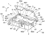
- FIG. 1 is a perspective view of a housing according to one embodiment of the invention
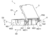
- FIG. FIG. 2 is a perspective view showing a closed state in which the lid of the housing of FIG. 1 is closed
- 2 is a perspective view of the housing of FIG. 1 as seen from another direction
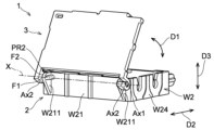
- FIG. FIG. 2 is a perspective view of the housing of FIG. 1 as seen from yet another direction
- 1 is a schematic diagram showing a vehicle provided with a housing according to an embodiment of the invention
- FIG. FIG. 2 is a top view showing a state in which a slider and a cable are connected to the housing of FIG. 1
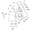
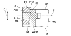
- FIG. 4 is a schematic view of the periphery of the shaft and bearing of the housing when the lid is in the open state, viewed in the axial direction
- FIG. 8 is a cross-sectional view taken along the line AA in FIG. 7;
- FIG. 4 is a schematic view of the surroundings of the shaft and bearing of the housing when the lid is in the closed state, viewed in the axial direction;
- FIG. 10 is a cross-sectional view taken along the line BB in FIG. 9;
- FIG. 10 is a reference diagram showing the surroundings of the shaft portion and the bearing portion of the housing and the surroundings of the engaging portion when the lid is in the closed state in the housing of the reference example that does not have the second projecting portion.
- FIG. 4 is a schematic view of the housing viewed in the axial direction, showing the periphery of the shaft and bearing portions of the housing and the periphery of the engaging portion when the lid is in the closed state;
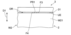
- FIG. 4 is a schematic diagram of a housing in which a protrusion forms a drainage channel between a lid and a side wall, as seen in the width direction;
- FIG. 5 shows a housing of a second embodiment, with protrusions provided on the housing body;
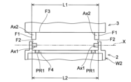
- FIG. 8 is a schematic diagram for explaining the positional relationship between the first axially facing surface and the second axially facing surface of the housing of the second embodiment;
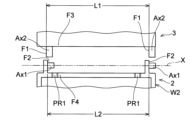
- FIG. 11 is a schematic diagram showing a modification of the positional relationship between the first axially facing surface and the second axially facing surface of the housing of the second embodiment;
- FIG. 11 is a schematic diagram showing another modification of the positional relationship between the first axially facing surface and the second axially facing surface of the housing of the second embodiment;
- a housing according to one embodiment of the present invention will be described below with reference to the drawings.
- the embodiments shown below are merely examples, and the housing of the present invention is not limited to the following embodiments.
- the terms “perpendicular to A” and similar expressions refer not only to directions completely perpendicular to A, but also to include directions that are substantially perpendicular to A. do.
- parallel to B and similar expressions refer not only to a direction completely parallel to B, but also to include being substantially parallel to B. do.
- C shape and similar expressions do not refer only to a perfect C shape, but also include a shape visually pronounced of a C shape (substantially C shape).
- the housing 1 of this embodiment includes a bottom wall W1 (see FIG. 1) and a side wall W2 extending from the bottom wall W1, and has an opening facing the bottom wall W1. It comprises a housing body 2 having an opening AP, and a lid 3 connected to a side wall W2 so as to rotate around a predetermined rotation axis X and closing the opening AP.
- the rotation axis X will be simply referred to as the axis X
- the direction in which the rotation axis X extends will be referred to as the axis X direction.
- the axis X direction is the same as the sliding direction of a slider S (see FIG. 6), which will be described later.
- the direction of the axis X is also the same direction in which a cable C (see FIG. 6), which will be described later, extends within the housing 1 .
- the direction in which the lid 3 opens and closes is called an opening/closing direction D1.
- the opening/closing direction D1 is substantially the same direction as the perspective direction with respect to the bottom wall W1 when the lid 3 is closed (see FIG. 2). becomes.
- the opening/closing direction D1 can also be rephrased as the direction in which the rear surface 31 of the lid 3 and the upper end UE of the side wall W2 face each other when the lid 3 is closed.
- a direction perpendicular to the axis X in a plane parallel to the lid 3 or the bottom wall W1 in the closed state is referred to as a width direction D2 of the housing 1.
- the width direction D2 of the housing is the base end portion side (base end region R2 described later) of the lid 3 on the axis X side and the tip end portion side (tip region R1 described later) of the lid 3. ).
- the direction perpendicular to both the X-axis direction and the width direction D2 is referred to as the height direction D3 of the housing 3 .
- the height direction D3 of the housing 1 is also the direction perpendicular to the back surface 31 of the lid 3 or the inner surface of the bottom wall W1 when the lid 3 is in the closed state. and substantially in the same direction.
- the housing 1 can suppress abnormal noise caused by vibration of the housing 1, and can be used as a housing to be attached to a mounting object having a vibration source, such as a vehicle, in an environment where vibration occurs. It is preferably used.
- the housing 1 has an internal space defined by a bottom wall W1, side walls W2 and a lid 3, and is opened and closed by the lid 3, as shown in FIGS.
- the internal space of the housing 1 accommodates a part or all of predetermined members.
- the housing 1 is configured to connect a cable C routed to the vehicle V, as shown in FIGS. 5 and 6 .
- the housing 1 includes a slider S that connects a plurality of cables C routed to the vehicle V, and a portion of the cable C that is connected to the slider S. be accommodated.
- the housing 1 is provided as part of the cable connecting mechanism M, as shown in FIGS.
- the cable connection mechanism M includes a housing 1, a cable (operating cable) C1, and a cable (first operated cable) C21 operated by the operating force of the cable C1. , a cable (second operated cable) C22 operated by the operating force of the cable C1, and a slider S housed in the housing 1 and connected to the ends of the cables C1, C21, and C22.
- the cables C1, C21, and C22 may be collectively referred to simply as the cable C.
- the cable C1 is directly or indirectly connected to the operation unit OP1 and operated by operating the operation unit OP1.
- the cable C1 can be an inner cable of a known control cable.
- the cable C1 may be housed in an outer casing OC (see FIG. 6) of the control cable between the housing 1 and the operating portion OP1.
- the cables C21 and C22 are connected to the cable C1 via the slider S, and are operated via the slider S that slides within the housing 1 by operating the cable C1.
- the cables C21 and C22 are directly or indirectly connected to the operated parts OP21 and OP22.
- the operated parts OP21 and OP22 are operated by operating the cables C21 and C22.
- the cables C21 and C22 can be inner cables of known control cables.
- the cables C21 and C22 may be accommodated in the outer casing OC (see FIG. 6) of the control cable between the housing 1 and the operated parts OP21 and OP22.
- the cable connecting mechanism M is an unlocking mechanism for unlocking the hood H of the vehicle V to which it is attached.
- the hood opener operating portion OP1
- the two lock members operated portion OP21 and operated portion OP22
- the housing 1 is provided in the engine room of the vehicle V or in the vicinity of the engine room.
- the housing may be provided in other unlocking mechanisms, such as seat reclining mechanisms having two locking members, and other cable coupling mechanisms.
- the object to which the cable coupling mechanism is attached is the vehicle V in this embodiment, it may be a structure other than the vehicle.
- a plurality (three) of cables C1, C21, and C22 are connected to the housing 1, but the number of cables connected to the housing 1 may be one or a plurality of cables. good too.
- the plurality of cables may be connected one-to-one, may be connected one-to-many, or may be connected many-to-many.
- the cable C is connected to the housing 1 via the slider S, but it may be connected to a member other than the slider S (for example, an operated member operated by the cable). , may be directly connected to the housing 1 (housing body 2).
- the slider S is a moving member configured to slide within the housing 1 .
- cables C1, C21, and C22 are connected to the slider S as shown in FIG.
- the slider S moves to one side (downward) in the sliding direction of the slider S (axis X direction; vertical direction in FIG. 6) by operating the cable C1.
- the cables C21 and C22 are pulled to one side in the sliding direction.
- the housing body 2 has a bottom wall W1, side walls W2, and an opening AP that opens so as to face the bottom wall W1.
- the internal space of the housing body 2 accommodates part or all of a predetermined member to be accommodated.
- the housing body 2 accommodates the slider S and part of the cables C1, C21, and C22.
- the opening AP of the housing body 2 is closed by the lid 3 while the members are housed in the housing body 2 (see FIG. 2). 1 to 4, the slider S and the cables C1, C21, and C22 are omitted for convenience of explanation, and the lid 3 is removed in FIG.
- the material forming the housing body 2 is not particularly limited as long as it has a predetermined rigidity. It is preferable that the housing body 2 have a predetermined rigidity and be slightly bent when an external force is applied to the housing body 2 .
- the housing body 2 can be made of synthetic resin, metal, or the like.
- the overall shape of the housing body 2 is not particularly limited as long as it can accommodate a predetermined member to be accommodated.
- the housing body 2 is shaped like a substantially rectangular box having an opening AP on one side.
- the housing body 2 is substantially rectangular with a bottom wall W1 formed in a substantially rectangular shape and side walls W2 erected from the bottom wall W1 in the shape of a rectangular frame. is formed in the shape of a box.
- the side wall W2 includes a first side wall W21 extending along the rotation axis X, a second side wall W22 facing the first side wall W21, and an end of the first side wall W1 on one side in the direction of the axis X. and a fourth side wall W24 extending from the other end of the first side wall W21 in the axial X direction toward the second side wall W22.
- the bottom wall W1 is a wall-shaped portion that defines the internal space of the housing body 2 together with the side wall W2.
- the bottom wall W1 is configured to at least partially support an object to be accommodated in the housing body 2 .
- the bottom wall W ⁇ b>1 is formed in a plate shape, and the inner surface of the bottom wall W ⁇ b>1 serves as the sliding surface of the slider S that slides within the housing 1 .
- the shape and structure of the bottom wall W1 is not particularly limited as long as it is configured to be able to partially support the object to be housed. may have
- the side wall W2 is a wall-shaped portion that defines the internal space of the housing body 2 together with the bottom wall W1.
- the side wall W2 is erected in a direction away from the inner surface of the bottom wall W1.
- the upper end UE (see FIG. 1) of the side wall W2 on the side of the opening AP of the side wall W2 (the end on the far side from the bottom wall W1) is in a closed state where the lid 3 closes the opening AP. It faces the rear surface 31 of the lid 3 .
- the side wall W2 extends in a direction (height direction D3) perpendicular to the inner surface of the bottom wall W1, but the side wall W2 is inclined with respect to the direction perpendicular to the inner surface of the bottom wall W1. may be extended.
- the side wall W2 includes a first side wall W21, a second side wall W22, a third side wall W23 and a third side wall W23 when viewed from a direction perpendicular to the inner surface of the bottom wall W1.
- Four side walls W24 are formed so as to be arranged in a substantially rectangular shape.
- the first side wall W21 and the second side wall W22 extend parallel to each other perpendicularly to the inner surface of the bottom wall W1.
- the third sidewall W23 and the fourth sidewall W24 are perpendicular to the inner surface of the bottom wall W1 and perpendicular to the inner surfaces of the first sidewall W21 and the second sidewall W22. extending parallel to each other.
- the side walls may have other shapes such as circular, elliptical, and polygonal shapes other than rectangular when viewed from a direction perpendicular to the inner surface of the bottom wall W1.
- the side wall W2 is provided with a shaft portion Ax1 when the lid 3 is provided with a bearing portion Ax2 as shown in FIGS.
- the side wall W2 is provided with a bearing portion.
- the first side wall W21 is provided with a shaft portion Ax1
- the shaft portion Ax1 of the first side wall W21 is provided with a bearing portion Ax2 provided in the lid 3. is attached, and the lid 3 rotates around the shaft Ax1.
- the shaft portion Ax1 (or bearing portion) may be provided on a side wall other than the first side wall W21 (for example, the third side wall W23 and the fourth side wall W24). The shaft portion Ax1 and the bearing portion Ax2 will be described later.
- the side wall W2 has, on one end side and the other end side in the direction of the axis X, outer casing attachment portions AT to which outer casings OC of control cables are attached.
- the outer casing attachment portion AT is a recessed portion cut from the upper end UE of the side wall W2 (the third side wall W23 and the fourth side wall W24) toward the bottom wall W1.
- the side wall W2 protrudes by a predetermined amount in the width direction D2 of the housing 1 from the inner edge of the upper end UE of the side wall W2, as shown in FIGS. It has a detachment prevention part P.
- the detachment prevention portion P extends for a predetermined length in the X-axis direction. As shown in FIG. 6, the detachment prevention portion P is accommodated in the housing 1 by facing both ends of the slider S in the width direction D2 in the direction (height direction D3) perpendicular to the inner surface of the bottom wall W1. detachment of the slider S from the housing 1 is suppressed.
- the non-formation region where the detachment preventing portion P is not provided is configured to be longer than the length of the slider S in the X-axis direction. In this case, the slider S can be easily accommodated in the housing 1 and removed from the non-formed region where the detachment prevention portion P is not provided.
- the second side wall W22 is provided with a fixing portion FX for attaching the housing 1 to an attachment target.
- the side wall W2 portion of the housing 1 is fixed to the mounting object via the fixing portion FX, and the housing 1 is fixed at a predetermined position of the mounting object.
- the fixing portion FX may be provided at other parts of the housing 1 such as the other side walls W21, W23, W24, the bottom wall W1, the lid 3, or the like.
- the lid 3 is attached to the housing body 2 so as to be rotatable around the rotation axis X by the shaft portion Ax1 and the bearing portion Ax2.
- the lid 3 covers and closes the opening AP of the housing body 2, and by moving in the opening/closing direction D1 in the opening direction, the lid 3 moves from the opening AP of the housing body 2. It makes it possible to access the inner space of the housing body 2 (for example, to remove the slider S and the cable C from the inner space).
- the lid 3 has a surface 32 which is the outer surface of the housing 1 when the lid 3 is closed (see FIG. 2), and a back surface 31 which faces the upper end UE of the side wall W2 when the lid 3 is closed.
- the lid 3 has bearing portions Ax2 projecting substantially perpendicularly to the rear surface 31 of the lid 3 at both ends of the proximal end of the lid 3 in the direction of the axis X. As shown in FIG.
- the material forming the lid 3 is not particularly limited as long as it has a predetermined rigidity. It is preferable that the lid 3 has a predetermined rigidity and is configured to bend slightly when an external force is applied to the lid 3 .
- the lid 3 can be made of synthetic resin, metal, or the like.
- the overall shape of the lid 3 is not particularly limited as long as it can close the opening AP of the housing body 2 .
- the term “closed” as used herein means that the opening AP can be closed so that the object accommodated in the housing main body 2 does not leave the housing main body 2 . Therefore, for example, if the opening AP of the housing body 2 is partially covered so that the object to be accommodated does not leave the opening AP, the lid 3 does not need to cover the entire opening AP, and the lid 3 does not need to cover the surface 32 of the housing body 2 . and the rear surface 31 may have a through hole penetrating therethrough.
- the lid 3 is formed in a substantially rectangular shape that is slightly larger than the opening AP so as to cover the entire substantially rectangular opening AP.
- the housing main body 2 and/or the lid 3 are held in the distal end region R1 on the far side from the rotation axis X with the lid 3 closing the opening AP.
- the engaging portion E1 holds the lid 3 in the closed state by engaging with the engaged portion E2 provided on the housing body 2 and/or the lid 3 .
- the “tip region R1” is defined as 1/2 of the distance between the distal position (tip portion) farthest from the axis X in the housing body 2 or the lid 3 and the axis X.
- the following area more preferably 1/4 to 1/3 or less of the distance between the distal position and the axis X, from the distal position.
- proximal end region R2 is a region of the housing body 2 or the lid 3, from the axis X (proximal end) to 1/2 or less of the distance between the distal position and the axis X, more preferably. is the area from the axis X to 1/4 to 1/3 or less of the distance between the distal position and the axis X of rotation.
- the engaging portion E1 is an engaging claw provided in the tip region R1 of the lid 3 in this embodiment. More specifically, as shown in FIG. 2, the engaging portion E1 extends from the tip of the lid 3 extending along the upper end of the second side wall W22 when the lid 3 is in the closed state. is an engaging claw extending in a direction approaching the bottom wall W1 in the height direction D3 on the outer surface side of.
- the engaged portion E2 is provided on the outer surface of the second side wall W22 at a position corresponding to the position of the engaging portion E1 (engaging claw) of the lid 3 in the closed state. It is an engagement stepped portion that can be engaged with.
- the shape and structure of the engaging portion E1 are not particularly limited as long as the lid 3 can be maintained in a closed state, and may be a known engaging structure other than engaging claws.
- the lid 3 is provided with the engaging portion E1 and the housing main body 2 is provided with the engaged portion E2.
- the lid 3 may be provided with an engaged portion (engaging stepped portion), or both the lid 3 and the housing body 2 may be provided with engaging portions, and both the lid 3 and the housing body 2 may be engaged. section may be provided.
- the engaging portion E1 and the engaged portion E2 are configured to engage with each other on the second side wall W22.
- the engaged portion may be configured to engage.
- one of the housing body 2 and the lid 3 has the shaft Ax1, and the other of the housing body 2 and the lid 3 pivotally supports the shaft Ax1 so that the lid 3 rotates about the rotation axis X. It has a bearing portion Ax2.
- the shaft portion Ax1 and the bearing portion Ax2 constitute a bearing structure that rotates the lid 3 with respect to the housing body 2 .
- the housing body 2 has the shaft portion Ax1 and the lid 3 has the bearing portion Ax2. You may have an axial part.
- the positions at which the shaft portion Ax1 and the bearing portion Ax2 are provided are not particularly limited as long as the lid 3 can be rotated with respect to the housing body 2 .
- the bearing structure composed of the shaft portion Ax1 and the bearing portion Ax2 is provided along the first side wall W21. may have been
- the shaft portion Ax1 is pivotally supported by the bearing portion Ax2 so that the lid 3 can rotate around the axis X with respect to the housing body 2.
- the shape and structure of the shaft portion Ax1 and the bearing portion Ax2 are not particularly limited as long as the lid 3 is configured to be rotatable about the axis X with respect to the housing body 2 .
- the shaft portion Ax1 has a columnar portion extending in the direction of the axis X, and the bearing portion Ax2 is an insertion portion (a circular through hole or an inner an insertion passage having a partially arcuate portion).
- the shaft Ax1 itself is configured so as not to rotate as a part of the housing body 2. However, when the shaft Ax1 is provided on the lid 3, the shaft Ax1 rotates relative to the bearing Ax2. Rotate. At least a part of the outer circumference of the shaft Ax1 is covered with the bearing Ax2, so that the lid 3 is separated from the housing body 2 when the shaft Ax1 and the bearing Ax2 rotate relative to each other. is suppressed.
- the shaft portion Ax1 may be entirely covered with the bearing portion Ax2 like the shaft portion Ax1 on the left side in FIG. Only a part of the outer circumference of Ax1 may be covered, and other parts of the outer circumference of shaft Ax1 may not be covered.
- the shaft portion Ax1 provided on one side of the lid 3 in the X-axis direction is inserted into the bearing portion Ax2 having a through hole penetrating in the X-axis direction, and then the other side of the lid 3 in the X-axis direction.
- the shaft portion Ax1 provided on the side can be fitted into the U-shaped bearing portion Ax2, thereby facilitating attachment of the lid 3 to the housing body 2. As shown in FIG.
- a predetermined gap (Figs. 7 and 8 ) are formed. This facilitates relative rotation between the shaft portion Ax1 and the bearing portion Ax2. As will be described later, due to the gap formed between the shaft portion Ax1 and the bearing portion Ax2, when the lid 3 is closed, a gap in the opening/closing direction is generated between the shaft portion Ax1 and the bearing portion Ax2 in the opening/closing direction D1. G2 occurs.
- the side wall W2 is formed on the opposite surface (the first side wall) provided on the lid 3 in the direction of the axis X of the rotation axis X when the lid 3 closes the opening AP of the housing body 2 . It has an opposing surface (second axially opposing surface) F2 that faces the axially opposing surface F1.
- the facing surface (first axially facing surface) F1 and the facing surface (second axially facing surface) F2 are configured to be pressed against each other in the X-axis direction at least when the lid 3 closes the opening AP. ing.
- the facing surface F1 and the facing surface F2 are configured to be pressed against each other in the direction of the axis X via the protrusion PR2 described later.
- the facing surface F1 and the facing surface F2 may be configured to be directly pressed against each other.
- the facing surface F1 and the facing surface F2 may be configured to be pressed against each other only in a state where the lid 3 closes the opening AP or in the vicinity thereof (closed vicinity region to be described later). They may be configured to be pressed against each other (for example, all the time) in areas other than the neighboring areas.
- this axial gap G1 there is an axial gap G1 of a predetermined size in the X-axis direction between the facing surfaces F1 and F2.
- this axial clearance G1 causes looseness in the axial X direction between the shaft portion Ax1 and the bearing portion Ax2.
- the axial gap G1 corresponds to the size of the gap between the shaft portion Ax1 and the bearing portion Ax2 that allows relative movement in the axial X direction.
- the first axially facing surface and the second axially facing surface are provided at portions different from the portions at which the shaft portion Ax1 and the bearing portion Ax2 are provided, the shaft portion Ax1 and the bearing portion Ax2.
- the facing surface F1 and/or the facing surface F2 has a projection (second projection) PR2 (FIGS. 1, 3 and 4) projecting from the facing surface F1 and/or the facing surface F2 in the direction of the axis X. 4).
- the protrusion PR2 presses the opposing surface F1 and the opposing surface F2 against each other in the direction of the axis X when at least the lid 3 closes the opening AP, and the lid 3 is closed. In this state, the lid 3 is restrained from moving relative to the housing body 2 in the X-axis direction.
- the shape, structure, and position of the opposing surface F1 and the opposing surface F2 are such that the opposing surface F1 and the opposing surface F2 are opposed to each other in the direction of the axis X, and at least one of the opposing surface F1 and the opposing surface F2 has a protrusion PR2.
- the facing surface F1 and the facing surface F2 are provided in the housing 1 at positions where the shaft portion Ax1 and the bearing portion Ax2 are provided.
- the first axially facing surface and the second axially facing surface may be separately provided at a portion different from the portion where the shaft portion Ax1 and the bearing portion Ax2 are provided.
- a pair of bearing structures (a shaft portion Ax1 and a bearing portion Ax2) provided at both ends in the axial X direction of the lid 3 and the first side wall W21 (for example, in the embodiment shown in FIG. 1, the projection portion PR1 is provided).
- a pair of projecting pieces projecting from the outer surface of the first side wall W21 may be provided, and each of the pair of projecting pieces may be provided with a first axially facing surface and a second axially facing surface.
- the facing surface F1 faces the facing surface F2 provided with the shaft portion Ax1 of the bearing portions Ax2 provided on both sides of the lid 3 in the axial X direction on the base end portion side of the lid 3. part.
- the facing surface F2 is the facing surface F1 of the protruding piece W211 (see FIGS. 3 and 4) having a shaft portion Ax1 that protrudes outward (in the width direction D2) from the outer surface of the first side wall W21 of the housing body 2. is the part facing the Further, the facing surface F1 and the facing surface F2 face each other in the X-axis direction in a region along the first side wall W21.
- the first axially facing surface and the second axially facing surface may face each other in the X-axis direction in a region along the third sidewall W23 or the fourth sidewall W24.
- the side wall W2 is provided on the lid 3 in the opening/closing direction D1 of the lid 3 in the proximal region R2 on the side of the rotation axis X when the lid 3 closes the opening AP. It has a facing surface (second opening/closing direction facing surface) F4 facing the surface (first opening/closing direction facing surface) F3. Further, although the details will be described later, the facing surface F3 and/or the facing surface F4 has a protruding portion PR1 that protrudes from the facing surface F3 and/or the facing surface F4 in the opening/closing direction D1. Although details of the projecting portion PR1 will be described later, the projecting portion PR1 prevents the lid 3 from moving relative to the housing body 2 in the opening/closing direction D1 when the lid 3 is closed.
- the facing surface F3 is a surface facing the fourth facing surface F4 of the side wall W2 in the opening/closing direction D1 (the height direction D3) in the base end region R2 of the lid 3 when the lid 3 is in the closed state.
- the facing surface F4 is a surface facing the facing surface F3 of the lid 3 in the opening/closing direction D1 (the height direction D3) in the proximal region R2 of the side wall W2 when the lid 3 is in the closed state.
- the positions, shapes, and structures of the facing surface F3 and the facing surface F4 are not particularly limited as long as they are surfaces facing each other in the proximal region R2. In this embodiment, as shown in FIG.
- the facing surface F4 is the upper end UE of the first side wall W21, and the facing surface F3 of the rear surface 31 of the lid 3 faces the upper end UE of the first side wall W21. It is a side to do.
- the facing surface F4 is, for example, the upper ends of the third side wall W23 and the fourth side wall W24, and the facing surface F3 faces the upper ends of the third side wall W23 and the fourth side wall W24 in the rear surface 31 of the lid 3. It can be a face.
- the position of the second opening/closing direction facing surface in the height direction D3 is a position further above the upper end UE of the side wall W2 according to the position of the first opening/closing direction facing surface in the height direction D3. Or it may be in the down position.
- a protrusion PR2 is provided in addition to the protrusion PR1 described later, but the protrusion PR2 may not necessarily be provided.
- the protruding portion PR2 is a protruding portion that protrudes in the axial X direction from the facing surface F1 and/or the facing surface F2.
- the protruding portion PR2 may be provided on the facing surface F1 on the lid 3 side, may be provided on the facing surface F2 on the housing body 2 side, or may be provided on both the facing surface F1 and the facing surface F2. may be provided.
- the amount of protrusion of the protrusion PR2 in the axial X direction is larger than the size of the axial gap G1 generated in the axial X direction between the opposing surfaces F1 and F2, and the protrusion PR2 is formed by the lid. 3 is configured to fit into the axial gap G1 with the opening AP closed.
- “fitting into the axial gap G1” refers to a state in which the protruding portion PR2 is press-fitted into the axial gap G1.
- the amount of protrusion of the protrusion PR2 is particularly limited as long as the protrusion PR2 can be fitted into the axial gap G1 to suppress relative movement of the lid 3 with respect to the housing body 2 in the axial X direction, as will be described later.
- the shape of the protrusion PR2 is not particularly limited as long as the protrusion PR2 can be fitted into the axial gap G1 to suppress relative movement of the lid 3 with respect to the housing body 2 in the axial X direction.
- bearing portions Ax2 provided at both ends of the base end portion of the lid 3 in the direction of the axis X have opposing surfaces F1 extending substantially perpendicularly to the axis X. It protrudes in the direction of the axis X with respect to the surface F1. 7, the projecting portion PR2 extends in a direction substantially perpendicular to the back surface 31 of the lid 3 when viewed in the direction of the axis X.
- a tip portion of the protruding portion PR2 that is first fitted into the axial gap G1 is configured to be tapered by a curved surface such as chamfering or an inclined surface, so that it can be easily fitted into the axial gap G1. .
- the lid 3 can move relative to the housing body 2 in the X-axis direction. Therefore, the lid 3 moves relative to the housing body 2 in the X-axis direction, resulting in rattling and abnormal noise.
- the protrusion PR2 is fitted into the axial gap G1, thereby filling the axial gap G1 and restricting the lid 3 from moving relative to the housing body 2 in the axial X direction. be.
- the protrusion PR2 when the protrusion PR2 is fitted between the facing surfaces F1 and F2 in the closed state of the lid 3, the protrusion PR2 extends from the facing surface F2 in a direction perpendicular to the facing surface F2 ( Left side in FIG. 10) receives a reaction force.
- the facing surface F1, the facing surface F2, and the projection PR2 are provided on both sides of the housing 1 in the X-axis direction. Reaction forces in directions opposite to each other are received in the direction of the axis X from the facing surface F2.
- relative movement of the lid 3 with respect to the housing body 2 in the X-axis direction is restricted while the projection PR2 is fitted in the axial gap G1. Therefore, when vibration or the like is applied to the housing 1, the occurrence of noise due to repeated contact and non-contact between the lid 3 and the housing body 2 in the direction of the axis X is suppressed.
- the positional relationship between the facing surface F1 and the facing surface F2 is such that the protrusion PR2 is fitted into the axial gap G1 so that the relative movement of the lid 3 with respect to the housing body 2 in the axial X direction can be restricted. It is not particularly limited as long as it can be inserted.
- the facing surface F1 and the facing surface F2 are provided so that the facing surface F2 is located inside the facing surface F1 in the axial X direction (the side close to the central portion of the side wall W2 in the axial X direction).
- the facing surface F1 and the facing surface F2 may be arranged in another positional relationship.
- the opposing surface F1 and the opposing surface F2 may be provided so that the opposing surface F1 is located inside the opposing surface F2 in the axial X direction (the side closer to the central portion of the side wall W2 in the axial X direction).
- one facing surface F1, one facing surface F2 and one axial gap G1 are provided at both ends in the axial X direction. Only one fitting structure (press-fitting structure) configured by the axial gap and the axial gap may be provided along the X-axis direction. For example, in FIG.
- a wall is provided on the left side of the bearing portion Ax2 of the lid 3 in order to restrict the movement of the lid 3 in the direction away from the facing surface F2 when the protrusion PR2 is fitted into the axial gap G1.
- the protrusion PR2 only needs to be fitted in the axial gap G1 when the lid 3 closes the opening AP. It may be fitted in the gap G1, or it may be fitted in the axial gap G1 during a part of the process of opening and closing the lid 3.
- the protrusion PR2 is provided on the facing surface F1 provided on the lid 3, and the protrusion PR2 is opened at a predetermined angle with respect to the housing body 2 from the closed state in which the lid 3 closes the opening AP. In the closed state, the cover 3 does not fit into the axial gap G1 (see FIG. 7), but fits into the axial gap G1 in the vicinity of the closed state where the lid 3 closes the opening AP (see FIG. 9). See) is configured as follows.
- the above-mentioned "predetermined angle" of the lid 3 with respect to the housing body 2 is not particularly limited. , preferably 45° or more, more preferably 30° or more.
- the "closed vicinity area" of the lid 3 is not particularly limited, for example, the angle ⁇ between the upper end UE of the side wall W2 and the back surface 31 of the lid 3 is greater than 0 and less than 60°, preferably greater than 0 and less than 45°. , more preferably the position of the lid 3 when greater than 0 and less than 30°.
- the protrusion (first protrusion) PR1 is a protrusion that protrudes in the opening/closing direction D1 from the facing surface (first opening/closing direction facing surface) F3 and/or the facing surface (second opening/closing direction facing surface) F4.
- the protruding portion PR1 may be provided on the facing surface F3 on the lid 3 side, may be provided on the facing surface F4 on the housing main body 2 side, or may be provided on both the facing surface F3 and the facing surface F4. may be provided.
- the amount of protrusion of the protrusion PR1 in the opening/closing direction D1 is larger than the size of the opening/closing direction gap G2 (see FIG. 7) generated between the shaft portion Ax1 and the bearing portion Ax2 in the opening/closing direction D1, and the lid 3 is positioned at the opening AP.
- the projecting portion PR1 is pressed against the facing surface F3 and/or the facing surface F4 in the opening/closing direction D1, thereby causing the shaft portion Ax1 to move toward the bearing portion Ax2 in the opening/closing direction. It is configured to be pressed against D1. Although the details will be described later, this restricts the relative movement of the lid 3 with respect to the housing body 2 in the opening/closing direction D1.
- the amount of protrusion of the protrusion PR1 is such that when the lid 3 closes the opening AP and is held by the housing body 2, the protrusion PR1 is pressed against the opposing surface F3 and/or the opposing surface F4 in the opening/closing direction D1. is not particularly limited as long as the shaft portion Ax1 is pressed against the bearing portion Ax2 in the opening/closing direction D1.
- the shape of the protruding portion PR1 is such that when the lid 3 closes the opening AP and is held by the housing body 2, the protruding portion PR1 is pressed against the opposing surface F3 and/or the opposing surface F4 in the opening/closing direction D1.
- the shaft portion Ax1 is not particularly limited as long as it is configured to be pressed against the bearing portion Ax2 in the opening/closing direction D1.
- the protrusion PR1 is a substantially rectangular protrusion extending along the X-axis direction.
- the lid 3 is held by the housing body 2 means that the lid 3 is maintained in a state in which the opening AP is closed by the engaging portion E1 or the like. Note that the lid 3 may be held by the housing body 2 by means other than the engaging portion E1.
- the position where the protrusion PR1 is provided is not particularly limited as long as the protrusion PR1 is provided in the base end region R2 of the lid 3 and/or the housing body 2.
- the protruding portion PR1 is provided in the base end region R2 of the rear surface 31 of the lid 3 facing the upper end UE of the first side wall W21.
- the protruding portion PR1 may be provided on the back surface 31 of the lid 3 facing the upper end UE of the third side wall W23 and/or the fourth side wall W24, or may be provided on the other portion of the lid 3. good too.
- the protrusion PR1 may be provided at the upper end UE of the first side wall W21, or may be provided at the upper end UE of the third side wall W23 and/or the fourth side wall W24. Alternatively, it may be provided in a part of the housing body 2 other than that.
- the protrusion PR1 is provided so as to be pressed against the facing surface F4 in the central region of the first side wall W21 in the direction of the axis X.
- the lid 3 is more likely to bend than when the protruding portion PR1 is provided on the end side of the first side wall W21 in the X-axis direction.
- the lid 3 can be easily closed.
- the protrusion may be configured to be pressed against the facing surface F3, or the protrusion may be formed between the first side wall W21 and the lid 3.
- the protrusion is pressed against the opposing surface F3 and the opposing surface F4.
- a plurality of protruding portions PR1 may be provided.
- the amount of protrusion of the protrusion PR1 in the opening/closing direction D1 is larger than the size of the gap G2 in the opening/closing direction. is pressed against the opposing surface F3 and/or the opposing surface F4 in the opening/closing direction D1, and the shaft portion Ax1 is pressed against the bearing portion Ax2 in the opening/closing direction D1. As a result, the lid 3 is prevented from moving relative to the housing body 2 in the opening/closing direction D1.
- “pressed in the opening/closing direction D1" and “pressing in the opening/closing direction D1" include not only the strict opening/closing direction D1 but also directions inclined with respect to the opening/closing direction D1.
- the shaft portion Ax1 is pressed against the bearing portion Ax2 in the opening/closing direction D1
- a pressing force is applied in the opening/closing direction D1 between the shaft portion Ax1 and the bearing portion Ax2.
- the bearing portion Ax2 may be relatively moved with respect to the shaft portion Ax1 and a pressing force may be applied between the shaft portion Ax1 and the bearing portion Ax2 in the opening/closing direction D1.
- a pressing force may be applied between the shaft portion and the bearing portion in the opening/closing direction D1.
- an opening/closing direction gap G2 is formed between the shaft portion Ax1 and the bearing portion Ax2.
- the opening/closing direction gap G2 is a gap caused by a clearance between the outer circumference of the shaft portion Ax1 and the inner surface of the bearing portion Ax2.
- a gap is formed between the outer circumference of the shaft portion Ax1 and the bearing portion Ax2 in a direction other than the opening/closing direction D1.
- the size of the opening/closing direction gap G2 is the size of the gap when the shaft portion Ax1 is moved to maximize the gap in the opening/closing direction D1 (height direction D3) with respect to the bearing portion Ax2. It refers to the size (maximum gap in the radial direction of the shaft portion Ax1).
- the opening/closing direction gap G2 is exaggerated in size to facilitate the explanation (the same applies to the axial direction gap G1).
- the opening/closing direction gap G2 allows the lid 3 in the closed state to move relative to the housing body 2 in the opening/closing direction D1 (the height direction D3). In this case, when the housing 1 is vibrated, the relative movement of the lid 3 with respect to the housing body 2 causes rattling and noise.
- the lid 3 when a protrusion PR1 having a protrusion amount larger than the opening/closing direction gap G2 is provided on the facing surface F3, when the lid 3 is closed, the protrusion PR1 PR1 contacts the facing surface F4 and is pressed toward the facing surface F4. More specifically, the lid 3 is configured to be able to close the housing body 2 even without the protrusion PR1. The lid 3 is closed while a pressing force is applied toward F4. As a result, a reaction force indicated by an arrow AR1 is applied from the opposing surface F4 to the projecting portion PR1 in a direction perpendicular to the opposing surface F4 (upward in FIG. 9).
- the lid 3 is held by the housing body 2 by the engaging portion E1.
- the means for holding the lid 3 in a closed state is not limited to the engaging portion E1 as long as the housing 1 is configured to be lifted away from W1.
- the case where the projecting portion PR1 is provided on the facing surface F3 has been described as an example, but as shown in FIG. , the same effect can be obtained in the case where they are provided on both the facing surface F3 and the facing surface F4.
- the cover 3 is provided with the bearing portion Ax2 and the housing body 2 is provided with the shaft portion Ax1.
- a similar effect can be obtained when a bearing portion is provided in 2 .
- the lid 3 closes the opening AP and is held by the housing body 2, and as shown in FIG. 13, the upper end UE of the side wall W2 on the opening AP side and the side wall W2.
- the projecting portion PR1 has a facing surface F3 and/or a facing surface F4 such that a drainage path DR connecting the inside and the outside of the housing 1 is formed between the rear surface 31 of the lid 3 facing the upper end UE of the . provided only in part of the In this case, as shown in FIG. 13, the water that has entered the interior of the housing 1 can be drained from the drainage channel DR formed between the lid 3 and the upper end UE of the side wall 2 .
- the drainage channel DR is formed by providing one second projecting portion PR2 in the central region of the first side wall W21 in the X-axis direction.
- a drainage channel is formed between the pair of projections PR1.
- the positions and number of protrusions provided are not particularly limited as long as a drainage channel can be formed.
- the slider S is accommodated in the housing body 2, and the cable C is connected to the slider S (see FIG. 6).
- the lid 3 is closed as shown in FIG.
- the projecting portion PR2 is press-fitted into the axial gap G1 between the facing surfaces F1 and F2.
- the lid 3 is closed, as shown in FIG. 12
- the protrusion PR1 is pressed against the facing surface F4 of the upper end UE of the first side wall W21, and the engaging portion E1 of the lid 3 is pushed into the housing body 2. Push toward the engaged portion E2.
- the lid 3 is closed while the protruding portion PR1 is pressed against the facing surface F4. At this time, the lid 3 engages the engaging portion E1 and the engaged portion E2 while pushing the distal end region R1 of the lid 3 with the projecting portion PR1 as a fulcrum, so that the lid 3 is in a slightly bent state.
- the protrusion PR2 is fitted into the axial gap G1, thereby suppressing relative movement of the lid 3 with respect to the housing body 2 in the axial X direction. Further, by pressing the projecting portion PR1 against the facing surface F4, relative movement of the lid 3 with respect to the housing body 2 in the opening/closing direction D1 is suppressed in the base end region R2 of the lid 3, and further, the tip region of the lid 3 is suppressed. Also at R1, relative movement of the lid 3 with respect to the housing body 2 in the opening/closing direction D1 is suppressed. Therefore, when vibration occurs in an object to which the housing 1 is attached, such as a vehicle, it is possible to suppress the generation of noise due to repeated contact and non-contact between the lid 3 and the housing body 2 .
- the housing 1 of the second embodiment will be explained using FIG. 14 and FIGS. 15A to 15C.
- the first axially facing surface F1 and the second axially facing surface F2 do not have the second protrusion PR2 in the first embodiment, and the protrusion PR1 is not the lid 3 but the side wall W2. is provided, which is different from the first embodiment.
- the configuration of this embodiment and the content described in the first embodiment can be used in combination.
- the facing surface (first axially facing surface) F1 and the facing surface (second axially facing surface) F2 are arranged in the axial X direction when at least the lid 3 closes the opening AP. configured to be pressed together. More specifically, as shown in FIG. 15A, lid 3 has a pair of first axially facing surfaces F1, F1 spaced apart in the direction of axis X, and sidewall W2 extends in the direction of axis X.
- the axial distance L2 between the facing surfaces F2, F2 is such that when the lid 3 is attached to the housing body 2, the first axially facing surface F1 and the second axially facing surface F2 are aligned with each other in the axial X direction. It is set to be pressed.
- the pair of first axially facing surfaces F1, F1 are located outside the pair of second axially facing surfaces F2, F2 in the axial X direction (end side of the housing 1).
- the axial distance L1 between the pair of first axially facing surfaces F1, F1 is greater than the axial distance L2 between the pair of second axially facing surfaces F2, F2. is set to be smaller (L1 ⁇ L2).
- the pair of first axially facing surfaces F1, F1 are located inside the pair of second axially facing surfaces F2, F2 in the axial X direction (the center side of the housing 1).
- the axial distance L1 between the pair of first axially facing surfaces F1, F1 is longer than the axial distance L2 between the pair of second axially facing surfaces F2, F2. It is set to be large (L1>L2). Also, as shown in FIG.
- one of the pair of first axially facing surfaces F1, F1 is located outside (housing 1 of the housing 1), and the other of the pair of first axially facing surfaces F1, F1 is located inside the other of the pair of second axially facing surfaces F2, F2 in the axial X direction ( center side), the distance L1 in the axial X direction between the pair of first axially facing surfaces F1, F1 is the distance in the axial X direction between the pair of second axially facing surfaces F2, F2. It is set to be greater than the distance L2 (L1>L2).
- the arrangement of the first axially facing surface F1 and the second axially facing surface F2 shown in FIGS. 15A to 15C is an example, and the first axially facing surface F1 and the second axially facing surface F2 Other arrangements are possible as long as they are set to press against each other in the X direction.
- a distance L1 in the axial X direction between the pair of first axially facing surfaces F1, F1 and an axis X between the pair of second axially facing surfaces F2, F2 The directional distance L2 is set such that when the lid 3 is attached to the housing body 2, the first axially facing surface F1 and the second axially facing surface F2 are pressed against each other in the direction of the axis X.
- the lid 3 when the lid 3 is attached to the housing body 2, no axial clearance is generated between the first axially facing surface F1 and the second axially facing surface F2. Therefore, when the lid 3 is closed, the lid 3 is prevented from moving relative to the housing body 2 in the X-axis direction. As a result, when the housing 1 vibrates, it is possible to suppress the occurrence of abnormal noise.
- the opening/closing direction D1 of the lid 3 with respect to the housing body 2 is prevented. Relative movement in (height direction D3) is suppressed. Therefore, when vibration is applied to the housing 1, abnormal noise is generated due to repeated contact and non-contact between the shaft portion Ax1 and the bearing portion Ax2 in the opening/closing direction D1. Abnormal noise due to repeated contact and non-contact is suppressed.
- the protrusion PR1 is located near the pair of the shaft portion Ax1 and the bearing portion Ax2 (for example, relative to the position where the shaft portion Ax1 and the bearing portion Ax2 are provided). , an area within 1/4 of the length of the housing 1 in the X-axis direction). More specifically, in FIG. 14, a pair of shaft portion Ax1 and bearing portion Ax2 are provided in the vicinity of both ends of the first side wall W21 in the X-axis direction. and inner neighboring region), a pair of protrusions PR1 are provided at the upper end UE of the first side wall W21.
- one protrusion is located at the center of the housing 1 in the X direction.
- the protrusion PR1 is closer to the shaft portion Ax1 and the bearing portion Ax2 than when provided. Therefore, when the lid 3 is held by the housing body 2 with the opening AP closed, the base end region R2 of the lid 3 moves away from the bottom wall W1 with the projection PR1 as a fulcrum (upper side in FIG. 12). It is possible to further improve the looseness reduction effect by being lifted up.
Landscapes
- Engineering & Computer Science (AREA)
- Mechanical Engineering (AREA)
- General Engineering & Computer Science (AREA)
- Microelectronics & Electronic Packaging (AREA)
- Health & Medical Sciences (AREA)
- Oral & Maxillofacial Surgery (AREA)
- Pivots And Pivotal Connections (AREA)
- Hinges (AREA)
- Flexible Shafts (AREA)
- Casings For Electric Apparatus (AREA)
Abstract
Description
次に、第2実施形態のハウジング1について、図14および図15A~図15Cを用いて説明する。本実施形態では、第1軸方向対向面F1および第2軸方向対向面F2は、第1実施形態における第2突出部PR2を有しておらず、突出部PR1が蓋3ではなく、側壁W2に設けられている点で、第1実施形態と異なる。なお、以下の説明において、上述した実施形態と共通する事項についての説明は省略し、相違点を中心に説明する。なお、本実施形態の構成と、第1実施形態で説明した内容とは組み合わせて用いることができる。
2 ハウジング本体
3 蓋
31 蓋の裏面
32 蓋の表面
AP 開口部
AT アウターケーシング取付部
Ax1 軸部
Ax2 軸受部
C、C1、C21、C22 ケーブル
D1 開閉方向
D2 ハウジングの幅方向
D3 ハウジングの高さ方向
DR 排水路
E1 係合部
E2 被係合部
F1 対向面(第1軸方向対向面)
F2 対向面(第2軸方向対向面)
F3 対向面(第1開閉方向対向面)
F4 対向面(第2開閉方向対向面)
FX 固定部
G1 軸方向隙間
G2 開閉方向隙間
H フード
L1 一対の第1軸方向対向面の間の軸方向の距離
L2 一対の第2軸方向対向面の間の軸方向の距離
M ケーブル連結機構
OC アウターケーシング
OP1 操作部
OP21、OP22 被操作部
P 離脱防止部
PR1 突出部
PR2 第2突出部
R1 先端領域
R2 基端領域
S スライダ
UE 側壁の上端
V 車両
W1 底壁
W2 側壁
W21 第1側壁
W211 突出片
W22 第2側壁
W23 第3側壁
W24 第4側壁
X 回転軸
θ 側壁の上端と蓋の裏面とが為す角
Claims (7)
- 底壁および前記底壁から立設する側壁を備え、前記底壁に対向するように開口した開口部を有するハウジング本体と、
所定の回転軸まわりに回転するように前記側壁に接続され、前記開口部を閉鎖する蓋と
を備え、
前記ハウジング本体および前記蓋の一方が軸部を有し、前記ハウジング本体および前記蓋の他方が、前記蓋が前記回転軸まわりに回転するように前記軸部を軸支する軸受部を有し、
前記側壁は、回転軸側となる基端領域において、前記蓋が前記開口部を閉鎖した状態において、前記蓋の開閉方向で前記蓋に設けられた第1開閉方向対向面と対向する第2開閉方向対向面を有し、
前記第1開閉方向対向面および/または前記第2開閉方向対向面は、前記第1開閉方向対向面および/または前記第2開閉方向対向面から前記開閉方向に突出する突出部を有し、
前記突出部の前記開閉方向への突出量は、前記軸部と前記軸受部との間に前記開閉方向で生じる開閉方向隙間の大きさよりも大きく、前記蓋が前記開口部を閉鎖し、前記ハウジング本体に保持された状態で、前記突出部が前記第1開閉方向対向面および/または前記第2開閉方向対向面に前記開閉方向で押圧されることによって、前記軸部が前記軸受部に対して前記開閉方向に押圧されるように構成され、
前記側壁は、前記蓋が前記ハウジング本体の前記開口部を閉鎖した状態において、前記回転軸の軸方向で前記蓋に設けられた第1軸方向対向面と対向する第2軸方向対向面を有し、
前記第1軸方向対向面および前記第2軸方向対向面は、少なくとも前記蓋が前記開口部を閉鎖した状態において、前記軸方向で互いに押圧されるように構成されている、ハウジング。 - 前記蓋が前記開口部を閉鎖し、前記ハウジング本体に保持された状態で、前記開口部側となる前記側壁の上端と、前記側壁の上端に対向する前記蓋の裏面との間に、前記ハウジングの内部と外部とを接続する排水路が形成されるように、前記突出部は、前記第1開閉方向対向面および/または前記第2開閉方向対向面の一部のみに設けられている、請求項1に記載のハウジング。
- 前記ハウジング本体および/または蓋が、前記回転軸から遠い側となる先端領域に、前記蓋が前記開口部を閉鎖した状態で前記ハウジング本体と前記蓋とを保持するための係合部を有し、
前記係合部によって、前記蓋が前記開口部を閉鎖した状態で前記ハウジング本体に保持されたときに、前記突出部を支点として、前記蓋の前記基端領域が前記底壁から離れる方向に持ち上げられて、前記軸部が前記軸受部に対して押圧される、請求項1または2に記載のハウジング。 - 前記第1軸方向対向面および/または第2軸方向対向面は、前記第1軸方向対向面および/または前記第2軸方向対向面から前記軸方向に突出する第2突出部を有し、
前記第2突出部の前記軸方向への突出量は、前記第1軸方向対向面と前記第2軸方向対向面との間に前記軸方向に生じる軸方向隙間の大きさよりも大きく、前記第2突出部は、前記蓋が前記開口部を閉鎖した状態で、前記軸方向隙間に嵌まり込むように構成されている、請求項1~3のいずれか1項に記載のハウジング。 - 前記蓋が、前記軸方向で離間して配置された一対の前記第1軸方向対向面を有し、
前記側壁が、前記軸方向で離間して配置された一対の前記第2軸方向対向面を有し、
前記一対の前記第1軸方向対向面の間の軸方向の距離、および、前記一対の前記第2軸方向対向面の間の軸方向の距離は、前記蓋が前記ハウジング本体に取り付けられたときに、前記第1軸方向対向面および前記第2軸方向対向面が、前記軸方向で互いに押圧されるように設定されている、請求項1~3のいずれか1項に記載のハウジング。 - 前記第2突出部は、前記蓋に設けられた前記第1軸方向対向面に設けられ、
前記第2突出部は、前記蓋が前記開口部を閉鎖した閉鎖状態から前記ハウジング本体に対して所定の角度開放した状態では、前記軸方向隙間に嵌まり込まず、前記蓋が前記開口部を閉鎖する閉鎖状態の近傍となる閉鎖近傍領域で、前記軸方向隙間に嵌まり込むように構成されている、請求項4に記載のハウジング。 - 前記ハウジングは、車両に配索されるケーブルが接続されるように構成されている、請求項1~6のいずれか1項に記載のハウジング。
Priority Applications (2)
| Application Number | Priority Date | Filing Date | Title |
|---|---|---|---|
| US18/704,624 US20250011050A1 (en) | 2021-11-04 | 2022-11-04 | Housing |
| CN202280066208.6A CN118044345A (zh) | 2021-11-04 | 2022-11-04 | 壳体 |
Applications Claiming Priority (2)
| Application Number | Priority Date | Filing Date | Title |
|---|---|---|---|
| JP2021180574A JP7810544B2 (ja) | 2021-11-04 | 2021-11-04 | ハウジング |
| JP2021-180574 | 2021-11-04 |
Publications (1)
| Publication Number | Publication Date |
|---|---|
| WO2023080185A1 true WO2023080185A1 (ja) | 2023-05-11 |
Family
ID=86241163
Family Applications (1)
| Application Number | Title | Priority Date | Filing Date |
|---|---|---|---|
| PCT/JP2022/041107 Ceased WO2023080185A1 (ja) | 2021-11-04 | 2022-11-04 | ハウジング |
Country Status (4)
| Country | Link |
|---|---|
| US (1) | US20250011050A1 (ja) |
| JP (1) | JP7810544B2 (ja) |
| CN (1) | CN118044345A (ja) |
| WO (1) | WO2023080185A1 (ja) |
Citations (6)
| Publication number | Priority date | Publication date | Assignee | Title |
|---|---|---|---|---|
| JPH0345692U (ja) * | 1989-09-11 | 1991-04-26 | ||
| JPH0415276U (ja) * | 1990-05-28 | 1992-02-06 | ||
| JPH05343861A (ja) * | 1992-06-10 | 1993-12-24 | Matsushita Electric Ind Co Ltd | 電子機器用筺体 |
| JPH065286U (ja) * | 1992-06-15 | 1994-01-21 | ダイヤモンド電機株式会社 | 遠隔操作装置のケース |
| JP2005059778A (ja) * | 2003-08-18 | 2005-03-10 | Alpine Electronics Inc | 車載用機器の前面パネル装置 |
| JP2016066722A (ja) * | 2014-09-25 | 2016-04-28 | ブラザー工業株式会社 | 開閉カバーの開閉構造 |
Family Cites Families (4)
| Publication number | Priority date | Publication date | Assignee | Title |
|---|---|---|---|---|
| JP2019183994A (ja) * | 2018-04-13 | 2019-10-24 | 株式会社ハイレックスコーポレーション | 長尺部材接続機構 |
| US11970313B2 (en) * | 2018-12-12 | 2024-04-30 | Yeti Coolers, Llc | Insulating container |
| JP7542492B2 (ja) * | 2021-07-06 | 2024-08-30 | 株式会社ハイレックスコーポレーション | ケーブル連結機構 |
| US20240401389A1 (en) * | 2021-10-01 | 2024-12-05 | Music Express Llc | Hinge Assembly |
-
2021
- 2021-11-04 JP JP2021180574A patent/JP7810544B2/ja active Active
-
2022
- 2022-11-04 CN CN202280066208.6A patent/CN118044345A/zh active Pending
- 2022-11-04 WO PCT/JP2022/041107 patent/WO2023080185A1/ja not_active Ceased
- 2022-11-04 US US18/704,624 patent/US20250011050A1/en active Pending
Patent Citations (6)
| Publication number | Priority date | Publication date | Assignee | Title |
|---|---|---|---|---|
| JPH0345692U (ja) * | 1989-09-11 | 1991-04-26 | ||
| JPH0415276U (ja) * | 1990-05-28 | 1992-02-06 | ||
| JPH05343861A (ja) * | 1992-06-10 | 1993-12-24 | Matsushita Electric Ind Co Ltd | 電子機器用筺体 |
| JPH065286U (ja) * | 1992-06-15 | 1994-01-21 | ダイヤモンド電機株式会社 | 遠隔操作装置のケース |
| JP2005059778A (ja) * | 2003-08-18 | 2005-03-10 | Alpine Electronics Inc | 車載用機器の前面パネル装置 |
| JP2016066722A (ja) * | 2014-09-25 | 2016-04-28 | ブラザー工業株式会社 | 開閉カバーの開閉構造 |
Also Published As
| Publication number | Publication date |
|---|---|
| JP2023069025A (ja) | 2023-05-18 |
| CN118044345A (zh) | 2024-05-14 |
| US20250011050A1 (en) | 2025-01-09 |
| JP7810544B2 (ja) | 2026-02-03 |
Similar Documents
| Publication | Publication Date | Title |
|---|---|---|
| JP6479522B2 (ja) | ケーブル連結機構 | |
| JP6498136B2 (ja) | ケーブル連結機構 | |
| US9902372B2 (en) | Wiper arm | |
| US12203297B2 (en) | Unlocking device | |
| CN104768790A (zh) | 用于车辆的可折叠的燃料门壳体 | |
| US6921293B2 (en) | Connector structure | |
| WO2015019896A1 (ja) | 車両用ドアロック装置 | |
| WO2023080185A1 (ja) | ハウジング | |
| JP6439493B2 (ja) | エアクリーナハウジング | |
| US11936170B2 (en) | Wire guide device | |
| JP5153941B2 (ja) | パワーコンディショナー用筐体 | |
| JP2002303071A (ja) | 扉開閉機構 | |
| US20190359136A1 (en) | Door mirror apparatus for vehicle | |
| WO2022080503A1 (ja) | ケーブル連結機構 | |
| JP2013246914A (ja) | レバー式コネクタ | |
| JP7269813B2 (ja) | 点検口 | |
| WO2013005662A1 (ja) | レバー嵌合式コネクタ | |
| JP7333139B2 (ja) | ドアミラー | |
| JP3620428B2 (ja) | 筺体の開閉構造 | |
| JP5904414B2 (ja) | 防水コネクタ | |
| US8596483B2 (en) | Rotatable access closure element | |
| JP5299219B2 (ja) | 電気接続箱 | |
| WO2022149445A1 (ja) | コネクタホルダ | |
| KR102019700B1 (ko) | 무힌지 개폐구조를 갖는 구조체 | |
| KR101619985B1 (ko) | 범퍼 커버용 토잉 후크 캡의 힌지 장치 |
Legal Events
| Date | Code | Title | Description |
|---|---|---|---|
| 121 | Ep: the epo has been informed by wipo that ep was designated in this application |
Ref document number: 22890005 Country of ref document: EP Kind code of ref document: A1 |
|
| WWE | Wipo information: entry into national phase |
Ref document number: 202280066208.6 Country of ref document: CN |
|
| WWE | Wipo information: entry into national phase |
Ref document number: 2401002820 Country of ref document: TH |
|
| NENP | Non-entry into the national phase |
Ref country code: DE |
|
| 122 | Ep: pct application non-entry in european phase |
Ref document number: 22890005 Country of ref document: EP Kind code of ref document: A1 |