WO2023080002A1 - 画像形成装置 - Google Patents
画像形成装置 Download PDFInfo
- Publication number
- WO2023080002A1 WO2023080002A1 PCT/JP2022/039520 JP2022039520W WO2023080002A1 WO 2023080002 A1 WO2023080002 A1 WO 2023080002A1 JP 2022039520 W JP2022039520 W JP 2022039520W WO 2023080002 A1 WO2023080002 A1 WO 2023080002A1
- Authority
- WO
- WIPO (PCT)
- Prior art keywords
- control unit
- registration roller
- recording paper
- image forming
- tilt
- Prior art date
- Legal status (The legal status is an assumption and is not a legal conclusion. Google has not performed a legal analysis and makes no representation as to the accuracy of the status listed.)
- Ceased
Links
Images



Classifications
-
- G—PHYSICS
- G03—PHOTOGRAPHY; CINEMATOGRAPHY; ANALOGOUS TECHNIQUES USING WAVES OTHER THAN OPTICAL WAVES; ELECTROGRAPHY; HOLOGRAPHY
- G03G—ELECTROGRAPHY; ELECTROPHOTOGRAPHY; MAGNETOGRAPHY
- G03G15/00—Apparatus for electrographic processes using a charge pattern
- G03G15/65—Apparatus which relate to the handling of copy material
- G03G15/6555—Handling of sheet copy material taking place in a specific part of the copy material feeding path
- G03G15/6558—Feeding path after the copy sheet preparation and up to the transfer point, e.g. registering; Deskewing; Correct timing of sheet feeding to the transfer point
- G03G15/6567—Feeding path after the copy sheet preparation and up to the transfer point, e.g. registering; Deskewing; Correct timing of sheet feeding to the transfer point for deskewing or aligning
-
- B—PERFORMING OPERATIONS; TRANSPORTING
- B65—CONVEYING; PACKING; STORING; HANDLING THIN OR FILAMENTARY MATERIAL
- B65H—HANDLING THIN OR FILAMENTARY MATERIAL, e.g. SHEETS, WEBS, CABLES
- B65H7/00—Controlling article feeding, separating, pile-advancing, or associated apparatus, to take account of incorrect feeding, absence of articles, or presence of faulty articles
- B65H7/02—Controlling article feeding, separating, pile-advancing, or associated apparatus, to take account of incorrect feeding, absence of articles, or presence of faulty articles by feelers or detectors
- B65H7/14—Controlling article feeding, separating, pile-advancing, or associated apparatus, to take account of incorrect feeding, absence of articles, or presence of faulty articles by feelers or detectors by photoelectric feelers or detectors
-
- B—PERFORMING OPERATIONS; TRANSPORTING
- B65—CONVEYING; PACKING; STORING; HANDLING THIN OR FILAMENTARY MATERIAL
- B65H—HANDLING THIN OR FILAMENTARY MATERIAL, e.g. SHEETS, WEBS, CABLES
- B65H9/00—Registering, e.g. orientating, articles; Devices therefor
-
- B—PERFORMING OPERATIONS; TRANSPORTING
- B65—CONVEYING; PACKING; STORING; HANDLING THIN OR FILAMENTARY MATERIAL
- B65H—HANDLING THIN OR FILAMENTARY MATERIAL, e.g. SHEETS, WEBS, CABLES
- B65H9/00—Registering, e.g. orientating, articles; Devices therefor
- B65H9/002—Registering, e.g. orientating, articles; Devices therefor changing orientation of sheet by only controlling movement of the forwarding means, i.e. without the use of stop or register wall
-
- B—PERFORMING OPERATIONS; TRANSPORTING
- B65—CONVEYING; PACKING; STORING; HANDLING THIN OR FILAMENTARY MATERIAL
- B65H—HANDLING THIN OR FILAMENTARY MATERIAL, e.g. SHEETS, WEBS, CABLES
- B65H9/00—Registering, e.g. orientating, articles; Devices therefor
- B65H9/12—Registering, e.g. orientating, articles; Devices therefor carried by article grippers
-
- G—PHYSICS
- G03—PHOTOGRAPHY; CINEMATOGRAPHY; ANALOGOUS TECHNIQUES USING WAVES OTHER THAN OPTICAL WAVES; ELECTROGRAPHY; HOLOGRAPHY
- G03G—ELECTROGRAPHY; ELECTROPHOTOGRAPHY; MAGNETOGRAPHY
- G03G15/00—Apparatus for electrographic processes using a charge pattern
- G03G15/50—Machine control of apparatus for electrographic processes using a charge pattern, e.g. regulating differents parts of the machine, multimode copiers, microprocessor control
- G03G15/5029—Machine control of apparatus for electrographic processes using a charge pattern, e.g. regulating differents parts of the machine, multimode copiers, microprocessor control by measuring the copy material characteristics, e.g. weight, thickness
-
- B—PERFORMING OPERATIONS; TRANSPORTING
- B65—CONVEYING; PACKING; STORING; HANDLING THIN OR FILAMENTARY MATERIAL
- B65H—HANDLING THIN OR FILAMENTARY MATERIAL, e.g. SHEETS, WEBS, CABLES
- B65H2404/00—Parts for transporting or guiding the handled material
- B65H2404/10—Rollers
- B65H2404/15—Roller assembly, particular roller arrangement
- B65H2404/152—Arrangement of roller on a movable frame
- B65H2404/1526—Arrangement of roller on a movable frame both roller ends being journalled to be movable independently from each other
-
- B—PERFORMING OPERATIONS; TRANSPORTING
- B65—CONVEYING; PACKING; STORING; HANDLING THIN OR FILAMENTARY MATERIAL
- B65H—HANDLING THIN OR FILAMENTARY MATERIAL, e.g. SHEETS, WEBS, CABLES
- B65H2513/00—Dynamic entities; Timing aspects
- B65H2513/10—Speed
- B65H2513/11—Speed angular
-
- B—PERFORMING OPERATIONS; TRANSPORTING
- B65—CONVEYING; PACKING; STORING; HANDLING THIN OR FILAMENTARY MATERIAL
- B65H—HANDLING THIN OR FILAMENTARY MATERIAL, e.g. SHEETS, WEBS, CABLES
- B65H2557/00—Means for control not provided for in groups B65H2551/00 - B65H2555/00
- B65H2557/20—Calculating means; Controlling methods
- B65H2557/262—Calculating means; Controlling methods with key characteristics based on feed forward control
Definitions
- the present invention relates to an image forming apparatus having a function of correcting the inclination of recording paper.
- an image forming apparatus such as a copying machine or a multifunction machine
- the recording paper may be conveyed in a state of being inclined with respect to the predetermined conveying direction of the recording paper.
- the recording paper is conveyed to the image forming section in a tilted state, a tilted image is formed on the recording paper.
- a technique using a registration roller is known to correct the skew of the recording paper. For example, the rotation of the registration rollers is temporarily stopped, and after the leading edge of the recording paper hits the stopped registration rollers, the rotation of the registration rollers is restarted at an appropriate timing. When the recording paper collides with the stopped registration roller, the recording paper is bent, and as a result, the inclination of the recording paper is corrected.
- Patent Documents 1 to 3 disclose techniques for correcting the inclination of the recording paper without stopping the rotation of the registration rollers.
- Japanese Patent Application Laid-Open No. 2002-200001 discloses a technique for correcting the inclination of the recording paper by detecting the inclination of the recording paper with respect to a predetermined conveying direction of the recording paper and inclining the roller shaft of the registration roller according to the inclination of the recording paper. are doing.
- tilting the roller axis of the registration roller affects the timing at which the recording paper reaches the registration roller. Specifically, when one end of the roller shaft of the registration roller is tilted upstream in the transport direction, the distance between the registration roller and the recording paper is shortened, and the recording paper reaches the registration roller faster. On the other hand, when one end of the roller shaft of the registration roller is tilted downstream in the transport direction, the distance between the registration roller and the recording paper increases, and the recording paper reaches the registration roller later.
- the present invention has been made in view of the above circumstances, and an object of the present invention is to make it possible to correct the inclination of the recording paper while ensuring that the recording paper is supplied to the image forming section at appropriate timing.
- An image forming apparatus includes an image forming section that forms an image on a recording sheet, and an image forming section that is provided upstream of the image forming section in a predetermined recording sheet conveying direction.
- the registration rollers for sending out the paper, the first controller for controlling the rotation of the registration rollers, the tilt detection sensor for detecting the tilt of the recording paper with respect to the transport direction, and the initial state are perpendicular to the transport direction.
- a tilting mechanism that tilts the roller shaft of the registration roller upstream or downstream with respect to the transport direction, and based on the detection result of the tilt detection sensor, tilts the roller shaft upstream or downstream with respect to the transport direction with respect to the tilting mechanism.
- a second control unit that controls the tilt mechanism to return the tilted roller shaft to the initial state when the recording paper reaches the registration roller.
- the second control unit transmits tilt data indicating the direction and amount of tilting of the roller shaft to the first control unit.
- the first controller corrects the rotational speed of the registration roller based on the direction and amount of tilt of the roller shaft indicated by the tilt data received from the second controller.
- the roller shafts of the registration rollers are tilted according to the tilt of the recording paper, and when the recording paper reaches the registration rollers, the tilted roller shafts are returned to the initial state. tilt can be corrected. Further, since the rotation speed of the registration rollers is corrected based on the direction and amount of tilting of the roller shafts, recording paper can be supplied to the image forming section at a timing suitable for image formation even if the roller shafts are tilted. As a result, it is possible to correct the tilt of the recording paper while ensuring that the recording paper is supplied to the image forming section at appropriate timing.
- FIG. 1 is a schematic partial front view showing the structure of an image forming apparatus according to an embodiment of the invention
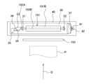
- FIG. 4 is a side view schematically showing a pair of registration rollers and a peripheral portion of the pair of registration rollers
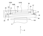
- FIG. 10 is a diagram for explaining an example of tilting operation of a pair of registration rollers
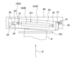
- FIG. 10 is a diagram for explaining another example of the tilting operation of the registration roller pair
- 2 is a functional block diagram schematically showing the main internal configuration of the image forming apparatus
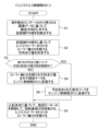
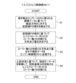
- FIG. 6 is a flow chart showing an example of a first roller axis tilting process
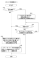
- 4 is a flowchart showing an example of first rotation speed adjustment processing
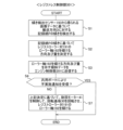
- It is a flow chart which shows an example of the 2nd roller axis inclination processing
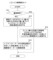
- 9 is a flowchart showing an example of second rotation speed adjustment processing; It is a flow chart which shows an example of the 3rd roller axis inclination processing.
- 9 is a flow chart showing an example of a third rotational
- FIG. 1 is a schematic partial front view showing the structure of an image forming apparatus according to the first embodiment of the invention.
- the image forming apparatus 1 is a multifunction machine having multiple functions such as a copy function, a printer function, a scanner function, and a facsimile function.
- the image forming apparatus 1 includes an image forming section 12 , a fixing section 13 , a paper feeding section 14 and a conveying section 19 .
- the image forming section 12 includes an intermediate transfer unit 120 , photoreceptor drums 121 for black, magenta, cyan, and yellow, and a secondary transfer roller 210 .
- the intermediate transfer unit 120 includes an intermediate transfer belt 125, a drive roller 125A, a driven roller 125B, and a primary transfer roller 126, the outer peripheral surface of which is transferred with a toner image.
- the intermediate transfer belt 125 is stretched between a driving roller 125A and a driven roller 125B.
- the intermediate transfer belt 125 is driven by a drive roller 125A while being in contact with the peripheral surface of the photoreceptor drum 121, so that the intermediate transfer belt 125 runs endlessly in synchronization with the photoreceptor drum 121.
- the toner images of each color (black, magenta, cyan, and yellow) transferred onto the intermediate transfer belt 125 are superimposed on the intermediate transfer belt 125 at adjusted transfer timings to form color toner images.
- the secondary transfer roller 210 sandwiches the intermediate transfer belt 125 and forms a nip portion N1 with the drive roller 125A.
- the secondary transfer roller 210 transfers the color toner image formed on the surface of the intermediate transfer belt 125 onto the recording paper P transported from the paper feeder 14 via the transport path 190 at the nip portion N1.
- the recording paper P onto which the toner image has been transferred at the nip portion N1 is conveyed to the fixing portion 13. As shown in FIG.
- the transport section 19 is provided along the transport path 190 and upstream of the nip portion N1 (that is, the image forming position where the image is formed by the image forming section 12) in the transport direction D of the recording paper P.
- an inclination detection sensor 193 provided along the transport path 190 on the upstream side in the transport direction D of the registration roller pair 191;
- a registration sensor 195 provided along the transport path 190 near the registration roller pair 191
- an intermediate sensor 196 provided along the transport path 190 near the intermediate transport roller pair 194.
- the registration roller pair 191 includes a driving registration roller 191A and a driven registration roller 191B that rotates following the driving registration roller 191A.
- the driving registration roller 191A and the driven registration roller 191B form a nip portion N2.
- the registration roller pair 191 sends out the recording paper P to the image forming section 12 .
- the registration roller pair 191 adjusts the timing of conveying the recording paper P to the nip portion N1.
- the tilt detection sensor 193 detects the tilt of the recording paper P with respect to the transport direction D.
- the tilt detection sensor 193 is a CIS (Contact Image Sensor), which is a type of line sensor.
- the tilt detection sensor 193 detects image data of one side of the recording paper P.
- FIG. The tilt detection sensors 193 are arranged in parallel in a direction orthogonal to the transport direction D. As shown in FIG.
- the intermediate conveying roller pair 194 conveys the recording paper P toward the registration roller pair 191 .
- the registration sensor 195 detects that the leading edge of the recording paper P has reached the registration roller pair 191 .
- the intermediate sensor 196 detects that the leading edge of the recording paper P has reached the intermediate conveying roller pair 194 .
- the registration sensor 195 and the intermediate sensor 196 are, for example, known reflective photoelectric sensors that include a light-emitting element and a light-receiving element that detects light emitted from the light-emitting element and reflected by the recording paper P. to detect the tip of the
- the paper feed unit 14 includes a plurality of paper feed cassettes 141 .
- Each paper feed cassette 141 includes a pickup roller 142 , a feed roller 143 , a retard roller 144 arranged to face the feed roller 143 , and a transport roller pair 145 .
- the pickup roller 142 picks up the recording paper P housed in the paper feed cassette 141 .
- the feed roller 143 and the retard roller 144 separate the recording paper P picked up by the pickup roller 142 one by one and convey it toward the conveying roller pair 145 .
- FIG. 2 is a side view schematically showing the registration roller pair 191 and the periphery of the registration roller pair 191.
- the registration roller pair 191 includes a driving registration roller 191A and a driven registration roller 191B, as shown in FIG.
- the driving registration roller 191A and the driven registration roller 191B respectively include roller shafts 192A and 192B (hereinafter sometimes simply referred to as "roller shafts 192").
- roller shaft 192A is located right behind the roller shaft 192B in the depth direction of FIG.
- the driving registration roller 191A is also positioned directly behind the driven registration roller 191B in the depth direction of FIG.
- the driving registration roller 191A, the driven registration roller 191B, and the roller shafts 192A and 192B are provided on the front side of the plane of FIG.
- the registration roller pair 191 is provided on the rotating substrate 30 .
- the rotary substrate 30 is provided with bearings 31 and 32 of the roller shaft 192A, a driving gear 33, a connecting gear 34, a shaft driving motor 35, and a support portion .
- the bearing 31 of the roller shaft 192A is provided over the bearing 31 of the roller shaft 192B, and the bearing 32 of the roller shaft 192A is provided over the bearing 32 of the roller shaft 192B. That is, bearings 31 and 32 of roller shaft 192B are provided on rotary substrate 30 via bearings 31 and 32 of roller shaft 192A (see FIG. 1).
- roller shaft 192A of the driving registration roller 191A rotatably support the roller shaft 192A (drive shaft).
- Bearings 31 and 32 of roller shaft 192B of driven registration roller 191B rotatably support roller shaft 192B (drive shaft).
- a driving gear 33 that rotates together with the roller shaft 192A is fixed to the shaft end of the roller shaft 192A of the driving registration roller 191A.
- the drive gear 33 meshes with a connection gear 34 fixed to the output shaft of the shaft drive motor 35 .
- the registration roller pair 191 is rotated by driving the shaft drive motor 35 .
- the support portion 36 is fixed to a support substrate 40 fixed to a part of the apparatus body of the image forming apparatus 1 .
- the support part 36 is, for example, a columnar protrusion, and is loosely fitted in a hole provided in the rotary base plate 30 .
- the supporting substrate 40 rotatably supports the rotating substrate 30 via the supporting portion 36 .
- the support substrate 40 is provided with a turning motor 41 and a pinion gear 42 attached to the output shaft of the turning motor 41 and rotating together with the output shaft.
- a rack gear 37 is provided at one end of the rotating board 30 on the bearing 32 side.
- the rack gear 37 meshes with a pinion gear 42 fixed to the output shaft of the turning motor 41 .
- the rotary substrate 30 rotates around the supporting portion 36 as a rotating shaft. Therefore, by rotating the turning motor 41 clockwise in the drawing, the bearing 32 side of the registration roller pair 191 is tilted toward the downstream side in the conveying direction D of the recording paper P with the bearing 31 side of the registration roller pair 191 as the center of rotation (hereinafter referred to as , this state is referred to as a state in which the registration roller pair 191 is tilted downstream in the transport direction D).
- FIG. 3 is a diagram showing an example of a state in which the registration roller pair 191 is tilted downstream in the transport direction D.
- the output shaft of the turning motor 41 rotates clockwise in the drawing
- the rotary substrate 30 rotates counterclockwise about the supporting portion 36 as the rotation axis
- the roller shaft 192 of the registration roller pair 191 tilts downstream in the transport direction D. .
- FIG. 4 is a diagram showing an example of a state in which the registration roller pair 191 is tilted upstream in the transport direction D.
- the output shaft of the swing motor 41 rotates counterclockwise in the drawing
- the rotary substrate 30 rotates clockwise around the support portion 36 as a rotation axis
- the roller shaft 192 of the registration roller pair 191 tilts upstream in the transport direction D. .
- the recording paper P is moved to the registration rollers.
- the sheet is conveyed in a posture that is not tilted with respect to the pair 191, enters the nip portion N2 (FIG. 1) formed by the pair of registration rollers 191, and is nipped.
- the rotary substrate 30 is rotated in the opposite direction to return the roller shaft 192 of the registration roller pair 191 to the initial state, thereby allowing the recording paper P can correct the slope of That is, the inclination of the recording paper P is corrected.
- FIG. 5 is a functional block diagram schematically showing the main internal configuration of the image forming apparatus 1.
- the image forming apparatus 1 includes a main control unit 100, an engine control unit 200, a registrationless control unit 300, a document feeding section 6, a document reading section 5, an image forming section 12, a fixing section 13, a paper feeding section 14, and a conveying section 19. , an operation unit 47 and a storage device 8 .
- the document feeding section 6 is provided on the upper surface of the document reading section 5 so as to be openable and closable by means of a hinge or the like.
- the document feeder 6 functions as a document pressing cover when reading a document placed on the platen glass.
- the document feeder 6 is an automatic document feeder called ADF (Auto Document Feeder).
- ADF Auto Document Feeder
- the document feeding section 6 has a document loading tray, and supplies the document placed on the document loading tray to the document reading section 5 .
- the document reading section 5 optically reads the image of the document supplied to the document reading section 5 by the document feeding section 6 or the document placed on the platen glass, and generates image data.
- Image data generated by the document reading unit 5 is stored in an image memory or the like.
- the image forming unit 12 Based on the image data generated by the document reading unit 5 or the image data received from a computer as an external device connected to the network, the image forming unit 12 records paper fed from the paper feeding unit 14. A toner image is formed on recording paper P as a medium.
- the fixing unit 13 heats and presses the recording paper P on which the toner image has been formed by the image forming unit 12 to fix the toner image onto the recording paper P.
- the recording paper P that has undergone the fixing process is discharged to the discharge tray.
- the paper feed unit 14 includes a plurality of paper feed cassettes 141 shown in FIG.
- the transport unit 19 transports the recording paper P toward the image forming unit 12 along the transport path 190 shown in FIG.
- the transport unit 19 includes a shaft drive motor 35, a drive motor 51 that supplies rotational driving force to the roller shafts of the intermediate transport roller pair 194 shown in FIG.
- a tilt detection sensor 193 is provided.
- the storage device 8 is a large-capacity storage device such as a HDD (Hard Disk Drive) or SSD (Solid State Drive).
- the storage device 8 stores various control programs and the like.
- the operation unit 47 includes various hard keys and the like.
- the operation unit 47 accepts user instructions, such as image forming operation execution instructions, regarding various operations and processes that can be performed by the image forming apparatus 1 via the hard keys.
- the operation unit 47 includes a display unit 473 that displays operation guidance and the like for the user.
- the operation unit 47 inputs a user's instruction based on the user's operation (touch operation) on the operation screen displayed on the display unit 473 via the touch panel of the display unit 473 or the user's operation on hard keys. accept.
- the display unit 473 is composed of an LCD (Liquid Crystal Display) or the like.
- the display unit 473 has a touch panel. When the user performs an operation of touching a button or key displayed on the screen, the touch panel receives an instruction associated with the touched position.
- the main control unit 100, engine control unit 200, and registrationless control unit 300 each include a processor, RAM (Random Access Memory), ROM (Read Only Memory), and a dedicated hardware circuit.
- the processor is, for example, a CPU (Central Processing Unit), an ASIC (Application Specific Integrated Circuit), or an MPU (Micro Processing Unit).
- the main control unit 100 functions as a main control section 101 through the operation of the processor according to the first control program stored in the storage device 8 .
- the engine control unit 200 functions as an engine control section 201 through the operation of the processor according to the second control program stored in the storage device 8 .
- the registrationless control unit 300 functions as a registrationless control section 301 through the operation of the processor according to the third control program stored in the storage device 8 .
- the first to third programs may be configured by the same control program.
- the engine control unit 201 and the registrationless control unit 301 are examples of the first control unit and the second control unit in the claims, respectively.
- main control unit 101 and the like can be configured by hardware circuits independently of the operation according to the control program by the main control unit 100 and the like.
- the engine control section 201 that controls the image forming section is provided separately from the main control section 101, but the present invention is not limited to this embodiment.
- the engine control section 201 and the main control section 101 may be integrated, and the main control section 101 may perform the functions and processes of the engine control section 201 .
- serial communication via the first communication line is used.
- the main control unit 101 controls the overall operation of the image forming apparatus 1 .
- the main control section 101 is connected to the operation section 47 .
- the main control unit 101 accepts an instruction input by a user's touch operation or the like on the operation unit 47 .
- the main control section 101 controls the display of the display section 473 .
- the engine control unit 200 is connected to the document feeding section 6 , the document reading section 5 , the image forming section 12 , the fixing section 13 , the paper feeding section 14 and the transport section 19 .
- An engine control unit 201 performs drive control and the like of these units.
- the engine control unit 201 controls rotation of the registration roller pair 191 in order to feed the recording paper P to the image forming unit 12 .
- engine control unit 201 performs rotation control of registration roller pair 191 by controlling shaft drive motor 35 .
- the registrationless control unit 300 is connected to the turning motor 41 and the tilt detection sensor 193 of the transport section 19 .
- the registrationless control unit 301 controls the turning motor 41 based on the detection result of the tilt detection sensor 193 to tilt the roller shaft 192 of the registration roller pair 191 upstream or downstream with respect to the transport direction D. , the inclination of the recording paper P is corrected.
- the registrationless control unit 301 uses serial communication to transmit tilt data indicating the direction and amount of tilting of the roller shaft 192 to the engine control unit 201 .
- the engine control unit 201 corrects the rotation speed of the registration roller pair 191 based on the direction and amount of tilting the roller shaft 192 indicated by the tilt data received from the registrationless control unit 301 .
- the engine control unit 201 makes a correction to slow down the rotation speed of the registration roller pair 191 . This adjusts the timing deviation.
- the registrationless control unit 301 performs the first roller axis tilting process when the leading edge of the recording paper P is detected based on the image data detected by the tilt detection sensor 193 .
- the registrationless control unit 301 detects the inclination of the recording paper P with respect to the transport direction D based on the image data detected by the inclination detection sensor 193 (step S1). Based on the detected inclination of the recording paper P, the registrationless control unit 301 adjusts the roller shafts 192 of the registration roller pair 191 so that the roller shafts 192 of the registration roller pair 191 are parallel to the leading edge of the recording paper P. The direction and amount of tilting are determined (step S2).
- the registrationless control unit 301 determines whether or not the difference between the direction and amount of tilting the roller shaft 192 determined this time and the direction and amount of tilting the roller shaft 192 determined last time is within a predetermined setting range. (Step S3).
- step S3 When the registration-less control unit 301 determines that the difference between the tilt direction and amount of the roller shaft 192 this time and the previous time is not within the predetermined set range (NO in step S3), the tilt direction and amount of the roller shaft 192 determined this time is determined. Inclination data indicating the direction and amount of inclination are transmitted to the engine control unit 201 by serial communication (step S4). After step S4, the registrationless control unit 301 controls the turning motor 41 to rotate the rotating substrate 30 based on the direction and amount of tilting of the roller shafts 192 determined this time, and the roller shafts 192 of the registration roller pair 191 are rotated. Tilt (step S5).
- the registration-less control unit 301 determines that the difference between the current time and the previous time is within a predetermined set range in terms of the direction and amount of tilting of the roller shaft 192 (that is, there is no large difference between the current time and the previous time). If so (YES in step S3), a predetermined command code having a data amount smaller than that of the tilt data is transmitted to the engine control unit 201 by serial communication (step S6). After step S6, the registrationless control unit 301 controls the turning motor 41 to rotate the rotating substrate 30 based on the direction and amount of tilting of the roller shafts 192 determined this time, and the roller shafts 192 of the registration roller pair 191 are rotated. Tilt (step S5).
- the registrationless control unit 301 may transmit, as the command code, data indicating a value that cannot be indicated by the tilt data, for example.
- engine control unit 201 performs the first rotational speed adjustment process when data transmitted by serial communication from registrationless control unit 301 is received.
- the engine control unit 201 determines whether or not the received data is tilt data (step S11). When the engine control unit 201 determines that the received data is tilt data (YES in step S11), it determines the rotation speed of the registration roller pair 191 according to the tilt direction and amount of the roller shaft 192 indicated by the tilt data. (step S12). For example, the non-volatile memory or storage device 8 incorporated in the engine control unit 200 stores a data table indicating the rotational speed of the registration roller pair 191 associated with the combination of the direction and amount of inclination of the roller shaft 192. . Using the data table, the engine control unit 201 determines the rotation speed of the registration roller pair 191 according to the tilt direction and amount of the roller shaft 192 indicated by the tilt data.
- the non-volatile memory or storage device 8 incorporated in the engine control unit 200 stores each coefficient associated with a combination of the direction and amount of tilting of the roller shaft 192 . Using the coefficient, the engine control unit 201 calculates and determines the rotational speed of the registration roller pair 191 according to the direction and amount of tilt of the roller shaft 192 indicated by the tilt data.
- step S12 the engine control unit 201 drives and controls the shaft drive motor 35 so that the rotation speed of the registration roller pair 191 becomes the determined rotation speed of the registration roller pair 191 (step S15). Thereby, the rotation speed of the registration roller pair 191 is corrected.
- step S15 is performed after the registration-less control unit 301 tilts the roller shafts 192 of the registration roller pair 191 based on the determined direction and amount of tilting the roller shafts 192 (that is, after step S5 shown in FIG. 6). ).
- step S13 determines whether the received data is a command code (YES in step S13).
- step S14 the rotation speed of the registration roller pair 191 according to the tilt direction and amount of the roller shaft 192 indicated by the tilt data received last time is determined. is determined using a data table or coefficients (step S14).
- step S15 the engine control unit 201 drives and controls the shaft drive motor 35 so that the rotation speed of the registration roller pair 191 becomes the determined rotation speed of the registration roller pair 191 (step S15). Thereby, the rotation speed of the registration roller pair 191 is corrected.
- step S15 when the registration control unit 301 receives a signal indicating that the leading edge of the recording paper P has been detected, which is transmitted from the registration sensor 195, the registration roller pair is controlled based on the reception timing of the signal.
- 191 calculates the nip timing at which the leading edge of the recording paper P is completely nipped (that is, the timing at which the recording paper P reaches the registration roller pair 191).
- the registrationless control unit 301 calculates the point of time when a predetermined time has passed from the reception timing as the nip timing.
- the registrationless control unit 301 controls the turning motor 41 to rotate the rotary substrate 30 and return the roller shafts 192 of the registration roller pair 191 to the initial state.
- the rotational speed of the registration roller pair 191 determined by the engine control unit 201 is returned to the initial state with the recording paper P nipped by the registration roller pair 191 tilted as described above.
- the rotation speed is set to be the timing reached when the registration roller pair 191 is in the initial state and the recording paper P is sent out by the registration roller pair 191 at the rotation speed before the correction.
- step S13 If the engine control unit 201 determines that the received data is not the command code (NO in step S13), that is, if the engine control unit 201 has received neither the tilt data nor the command code, the 1 ends the rotation speed adjustment process.
- the roller shaft 192 of the registration roller pair 191 is tilted in accordance with the tilt of the recording paper P, and at the timing when the leading edge of the recording paper P is completely nipped by the registration roller pair 191, the tilting Since the roller shafts 192 of the registration roller pair 191 are returned to the initial state, the inclination of the recording paper P can be corrected so that the edge of the leading edge of the recording paper P is perpendicular to the transport direction D. Further, since the rotation speed of the registration roller pair 191 is corrected based on the direction and amount of tilting of the roller shaft 192, the recording paper P is supplied to the image forming unit 12 at an appropriate timing even if the roller shaft 192 is tilted. can. As a result, the tilt of the recording paper P can be corrected while ensuring the supply of the recording paper P to the image forming section 12 at appropriate timing.
- the registrationless control unit 301 determines that the difference between the current and previous tilting directions and amounts of the roller shaft 192 is within a predetermined set range (that is, the current and previous tilting If it is determined that there is no large difference), instead of the tilt data, a command code having a smaller amount of data than the tilt data is transmitted to the engine control unit 201 by serial communication.
- the registrationless control unit 301 outputs the command code when it determines that the difference between the current and previous tilting directions and amounts of the roller shaft 192 is within a predetermined set range. Although it is transmitted to the engine control section 201, the present invention is not limited to such an embodiment. For example, as another embodiment, the registrationless control unit 301 limits the case where the direction and amount of tilting the roller shaft 192 determined this time and the direction and amount of tilting the roller shaft 192 determined last time are the same, The command code may be transmitted to engine control section 201 .
- the registrationless control unit 301 may execute transmission retry processing when detecting a communication abnormality in transmission of either the tilt data or the command code.
- an image forming apparatus 1 according to a second embodiment of the present invention will be described below with reference to the drawings.
- the registrationless control unit 301 executes the second roller axis tilting process instead of the first roller axis tilting process
- the engine control unit 201 has the same configuration as the image forming apparatus 1 according to the first embodiment, except that the second rotation speed adjustment process is executed instead of the first rotation speed adjustment process.
- the same configuration as that of the image forming apparatus 1 according to the first embodiment will not be repeatedly described.
- the registrationless control unit 301 performs the second roller axis tilting process when the leading edge of the recording paper P is detected based on the image data detected by the tilt detection sensor 193 .
- the registrationless control unit 301 detects the inclination of the recording paper P with respect to the transport direction D based on the image data detected by the inclination detection sensor 193 (step S1). Based on the detected inclination of the recording paper P, the registrationless control unit 301 adjusts the roller shafts 192 of the registration roller pair 191 so that the roller shafts 192 of the registration roller pair 191 are parallel to the leading edge of the recording paper P. The direction and amount of tilting are determined (step S2).
- the registrationless control unit 301 transmits tilt data indicating the determined direction and amount of tilting of the roller shaft 192 to the engine control unit 201 by serial communication (step S3). After step S3, the registrationless control unit 301 controls the turning motor 41 to rotate the rotating substrate 30 and tilt the roller shafts 192 of the registration roller pair 191 based on the determined direction and amount of tilting of the roller shafts 192. (Step S4).
- engine control unit 201 performs the second rotational speed adjustment process when data transmitted by serial communication from registrationless control unit 301 is received.
- the engine control unit 201 determines whether or not a communication error has occurred with respect to the tilt data transmitted by serial communication from the registrationless control unit 301 (step S11). In serial communication, the engine control unit 201 on the receiving side detects, for example, a known parity error, overrun error, or framing error as a communication error.
- step S11 When the engine control unit 201 determines that a communication error has not occurred (NO in step S11), the registration roller pair 191 rotates according to the direction and amount of inclination of the roller shaft 192 indicated by the normally received inclination data. A speed is determined (step S12). For example, the engine control unit 201 uses data tables or coefficients stored in the non-volatile memory or storage device 8 incorporated in the engine control unit 200 in the same manner as in the above-described first embodiment to determine the registration roller pair 191. Determines the rotation speed of
- step S12 the engine control unit 201 drives and controls the shaft drive motor 35 so that the rotation speed of the registration roller pair 191 becomes the determined rotation speed of the registration roller pair 191 (step S18). Thereby, the rotation speed of the registration roller pair 191 is corrected.
- step S18 is performed after the registration-less control unit 301 tilts the roller shafts 192 of the registration roller pair 191 based on the determined direction and amount of tilting the roller shafts 192 (that is, after step S4 shown in FIG. 8). ).
- the engine control unit 201 determines that no communication error has occurred, the engine control unit 201 transmits response data indicating that the tilt data has been received normally to the registrationless control unit 301 .
- step S11 when engine control unit 201 determines that a communication error has occurred (YES in step S11), that is, when detecting a communication error with respect to inclination data, engine control unit 201 changes the rotation speed of registration roller pair 191 to a predetermined value. Then, the adjustment process is performed (step S13).
- engine control unit 201 determines that a communication error has occurred, engine control unit 201 transmits response data to registrationless control unit 301 indicating that the tilt data could not be received normally.
- the registrationless control unit 301 executes retry processing for transmitting the tilt data.
- the engine control unit 201 for example, (i) sets the pair of registration rollers to a predetermined low speed that is lower than a predetermined rotation speed during normal times when no communication abnormality occurs. 191, (ii) based on the type or size of the recording paper P, perform processing to change the rotational speed of the pair of registration rollers 191, or (iii) the previously normally received tilt Based on the data, processing for correcting the rotation speed of the registration roller pair 191 is performed.
- the engine control unit 201 controls at least one of, for example, when the thickness of the recording paper P is out of the predetermined range and when the size of the recording paper P is out of the predetermined range.
- the rotation of the registration roller pair 191 may be temporarily stopped as a process of changing the rotation speed of the registration roller pair 191 .
- step S13 the engine control unit 201 determines whether or not the tilt data retransmitted by the retry processing by the registrationless control unit 301 has been successfully received (step S15).
- step S15 If the engine control unit 201 determines that the tilt data has been successfully received (YES in step S15), the engine control unit 201 determines the rotation speed of the registration roller pair 191 according to the tilt direction and amount of the roller shaft 192 indicated by the tilt data (step S12). After the process of step S12, the engine control unit 201 drives and controls the shaft drive motor 35 so that the rotation speed of the registration roller pair 191 becomes the determined rotation speed of the registration roller pair 191 (step S18). Thereby, the rotation speed of the registration roller pair 191 is corrected.
- step S18 the engine control unit 201 further determines the pair of registration rollers based on the type or size of the recording paper and the time required for recovery from the occurrence of the communication error to the normal reception of the tilt data.
- the rotational speed of 191 may be determined.
- the engine control unit 201 corrects the rotation speed of the registration roller pair 191 to be faster.
- the rotation speed of the registration roller pair 191 is determined so that the rotation speed of the registration roller pair 191 increases as the time required for recovery increases.
- the engine control unit 201 corrects the rotation speed of the registration roller pair 191 to be slow.
- the rotation speed of the registration roller pair 191 is determined so that the rotation speed of the registration roller pair 191 is further decreased as the time required for recovery increases.
- step S15 when the engine control unit 201 determines that the tilt data has not been successfully received (NO in step S15), based on the signal transmitted from the registration sensor 195, the leading edge of the recording paper P is detected by the registration roller pair. It is determined whether or not 191 has been reached (step S17).
- step S15 the engine control unit 201 successfully receives the tilt data retransmitted by the retry processing by the registrationless control unit 301. It is determined whether or not (step S15).
- the engine control unit 201 determines that the retransmitted tilt data has been successfully received before the leading edge of the recording paper P reaches the registration roller pair 191 (NO in step S17) (YES in step S15).
- the rotation speed of the registration roller pair 191 is determined according to the direction and amount of tilt of the roller shaft 192 indicated by the tilt data (step S12).
- step S12 engine control unit 201 performs the process of step S18.
- step S18 when the registrationless control unit 301 receives a signal indicating that the leading edge of the recording paper P has been detected, which is transmitted from the registration sensor 195, the same as in the first embodiment, A nip timing is calculated based on the reception timing of the signal.
- the registrationless control unit 301 controls the turning motor 41 to rotate the rotary substrate 30 and return the roller shafts 192 of the registration roller pair 191 to the initial state.
- the rotational speed of the registration roller pair 191 determined by the engine control unit 201 in step S12 is the speed at which the recording paper P is nipped by the registration roller pair 191 tilted as described above.
- the timing at which the leading edge of the recording paper P delivered by the registration roller pair 191 reaches the nip portion N1 between the intermediate transfer belt 125 and the driving roller 125A when the state is returned to the initial state is recorded in the transport direction D.
- the rotation speed is set to the timing that is reached when the paper P is not tilted, the registration roller pair 191 is in the initial state, and the recording paper P is delivered by the registration roller pair 191 at the rotation speed before correction. It is
- step S15 the engine control unit 201 does not determine that the retransmitted tilt data has been successfully received before the leading edge of the recording paper P reaches the registration roller pair 191 (NO in step S15, step YES in S17), the second rotational speed adjustment process is terminated.
- the engine control section 201 corrects the rotation speed of the registration roller pair 191 based on the direction and amount of inclination of the roller shaft 192 .
- the engine control unit 201 that performs control for rotating the registration roller and the registrationless control unit 301 that performs control for tilting the roller shaft 192 are independent. It is necessary to transmit the tilt data from 301 to the engine control unit 201 .
- the rotation speed of the registration roller pair 191 is adjusted in advance. Processing is done. Execution of the adjustment process suppresses adverse effects that occur when a communication error occurs with respect to the tilt data.
- the predetermined adjustment process as described above, for example, the correction of the rotation speed of the registration roller pair 191 is performed based on the tilt data normally received last time, or the normal adjustment process is performed when no communication abnormality occurs. For example, the rotation speed of the registration roller pair 191 may be made lower than the time.
- the engine control unit 201 controls the drive motor 51 to perform the predetermined adjustment process more than during normal times when no communication abnormality has occurred.
- a process of changing the rotation speed of the intermediate transport roller pair 194 to a slow predetermined low speed may be performed. As a result, it is possible to gain time until the communication abnormality is recovered.
- FIG. 1 An image forming apparatus 1 according to a third embodiment of the present invention will be described below with reference to the drawings.
- the registrationless control unit 301 executes the third roller axis tilting process instead of the first roller axis tilting process
- the engine control unit 201 has the same configuration as the image forming apparatus 1 according to the first embodiment, except that the third rotation speed adjustment process is executed instead of the first rotation speed adjustment process.
- the same configuration as that of the image forming apparatus 1 according to the first embodiment will not be repeatedly described.
- the registrationless control unit 301 performs the third roller axis tilting process when the leading edge of the recording paper P is detected based on the image data detected by the tilt detection sensor 193 .
- the registrationless control unit 301 detects the inclination of the recording paper P with respect to the transport direction D based on the image data detected by the inclination detection sensor 193 (step S1). Based on the detected inclination of the recording paper P, the registrationless control unit 301 adjusts the roller shafts 192 of the registration roller pair 191 so that the roller shafts 192 of the registration roller pair 191 are parallel to the leading edge of the recording paper P. The direction and amount of tilting are determined (step S2).
- the registrationless control unit 301 transmits tilt data indicating the determined tilt direction and amount of the roller shaft 192 to the engine control unit 201 via the first communication line by serial communication (step S3). After the process of step S3, the registrationless control unit 301 determines whether or not the non-execution notification has been received via the general-purpose port connected to the registrationless control unit 301 and enabling communication with the engine control unit 201. It judges (step S4).
- the engine control unit 201 causes control to tilt the roller shafts 192 of the registration roller pair 191.
- a predetermined non-execution notification for non-execution is transmitted to the registrationless control unit 301 through the general-purpose port.
- the rotation motor 41 is controlled based on the determined direction and amount of tilting of the roller shaft 192. to rotate the rotary substrate 30 to incline the roller shaft 192 of the registration roller pair 191 (step S7).
- step S4 when the registrationless control unit 301 determines that the non-execution notification has been received via the general-purpose port (YES in step S4), the third roller axis tilting process is performed without performing the process of step S7. finish.
- engine control unit 201 performs the third rotational speed adjustment process when data transmitted by serial communication from registrationless control unit 301 is received.
- the engine control unit 201 determines whether or not a communication error has occurred with respect to the tilt data transmitted by serial communication from the registrationless control unit 301 (step S11). In serial communication, the engine control unit 201 on the receiving side detects, for example, a known parity error, overrun error, or framing error as a communication error.
- step S11 When the engine control unit 201 determines that a communication error has not occurred (NO in step S11), the registration roller pair 191 rotates according to the direction and amount of inclination of the roller shaft 192 indicated by the normally received inclination data. A speed is determined (step S12). For example, the engine control unit 201 uses data tables or coefficients stored in the non-volatile memory or storage device 8 incorporated in the engine control unit 200 in the same manner as in the above-described first embodiment to determine the registration roller pair 191. Determines the rotation speed of
- step S12 the engine control unit 201 drives and controls the shaft drive motor 35 so that the rotation speed of the registration roller pair 191 becomes the determined rotation speed of the registration roller pair 191 (step S13). Thereby, the rotation speed of the registration roller pair 191 is corrected.
- step S18 is performed after the registration-less control unit 301 tilts the roller shafts 192 of the registration roller pair 191 based on the determined direction and amount of tilting the roller shafts 192 (that is, after step S7 shown in FIG. 10). ).
- step S13 when the registrationless control unit 301 receives a signal indicating that the leading edge of the recording paper P has been detected, which is transmitted from the registration sensor 195, the same as in the first embodiment, A nip timing is calculated based on the reception timing of the signal.
- the registrationless control unit 301 controls the turning motor 41 to rotate the rotary substrate 30 and return the roller shafts 192 of the registration roller pair 191 to the initial state.
- the rotational speed of the registration roller pair 191 determined by the engine control unit 201 in step S12 is the speed at which the recording paper P is nipped by the registration roller pair 191 tilted as described above.
- the timing at which the leading edge of the recording paper P delivered by the registration roller pair 191 reaches the nip portion N1 between the intermediate transfer belt 125 and the driving roller 125A when the state is returned to the initial state is recorded in the transport direction D.
- the rotation speed is set to the timing that is reached when the paper P is not tilted, the registration roller pair 191 is in the initial state, and the recording paper P is delivered by the registration roller pair 191 at the rotation speed before correction. It is
- step S11 determines that a communication error has occurred (YES in step S11), that is, if a communication error regarding the tilt data is detected, the engine control unit 201 is connected to the engine control unit 201 and is registered without registration.
- a predetermined non-execution notification for not performing control for tilting roller shaft 192 of registration roller pair 191 is directed to registrationless control unit 301 via a general-purpose port that enables communication with control unit 301. and transmit (step S14).
- engine control unit 201 transmits a non-execution notification to registrationless control unit 301 via a general-purpose port as a second communication line different from the first communication line that communicates inclination data. After the process of step S14, the engine control unit 201 ends the third rotational speed adjustment process.
- the engine control section 201 corrects the rotation speed of the registration roller pair 191 based on the direction and amount of inclination of the roller shaft 192 .
- the engine control unit 201 that performs control for rotating the registration roller and the registrationless control unit 301 that performs control for tilting the roller shaft 192 are independent. It is necessary to transmit the tilt data from 301 to the engine control unit 201 .
- the engine control unit 201 tilt data
- the registrationless control unit 301 transmitting side of the tilt data.
- the non-execution notification is transmitted via the second communication line different from the first communication line. It becomes possible to reliably transmit the notification of implementation to the registrationless control unit 301, thereby improving responsiveness.
- the engine control unit 201 transmits a non-execution notification to the registrationless control unit 301 by performing simple processing such as switching the signal from the general-purpose port as the second communication line, which is normally "Low", to "High". It is possible.
- the method of detecting a communication abnormality by the engine control unit 201 is not limited to the method of detecting a parity error, an overrun error, or a framing error as a communication abnormality as described above.
- the engine control unit 201 when the engine control unit 201 does not receive the tilt data within a predetermined time during which the tilt data should be received in normal times when there is no communication abnormality, the communication abnormality is detected. can be determined.
- the engine control unit 201 monitors the transport status of the recording paper P to measure a predetermined time for receiving the tilt data. For example, the engine control unit 201 detects the timing when the leading edge of the recording paper P reaches the intermediate transport roller pair 194 based on the signal obtained from the intermediate sensor 196, and the leading edge of the recording paper P reaches the intermediate transport roller pair 194. Measure the elapsed time from the point of arrival.
- the engine control unit 201 calculates the time T required for the leading edge of the recording paper P to reach the registration roller pair 191 after reaching the intermediate transportation roller pair 194 based on the rotational speed of the intermediate transportation roller pair 194 . If the inclination data is not received before the elapsed time reaches the time T, the engine control unit 201 determines that a communication error regarding the inclination data has occurred.
- the present invention is not limited to the configuration of the above embodiment, and various modifications are possible. Moreover, the configuration and processing of the above embodiment shown using FIGS. 1 to 11 are merely one embodiment of the present invention, and are not intended to limit the present invention to the configuration and processing.
Landscapes
- Physics & Mathematics (AREA)
- General Physics & Mathematics (AREA)
- Engineering & Computer Science (AREA)
- Microelectronics & Electronic Packaging (AREA)
- Registering Or Overturning Sheets (AREA)
- Delivering By Means Of Belts And Rollers (AREA)
- Control Or Security For Electrophotography (AREA)
Abstract
Description
以下、本発明の第1実施形態に係る画像形成装置について図面を参照して説明する。図1は、本発明の第1実施形態に係る画像形成装置の構造を示す模式的な部分正面図である。図1に示すように、画像形成装置1は、例えば、コピー機能、プリンター機能、スキャナー機能、及びファクシミリ機能のような複数の機能を兼ね備える複合機である。画像形成装置1は、画像形成部12、定着部13、給紙部14、及び搬送部19を含む。
以下、本発明の第2実施形態に係る画像形成装置1について図面を参照して説明する。第2実施形態に係る画像形成装置1は、レジストレス制御部301が、上記第1のローラー軸傾斜処理に代えて、第2のローラー軸傾斜処理を実行する点、及び、エンジン制御部201が、上記第1の回転速度調整処理に代えて、第2の回転速度調整処理を実行する点を除き、第1実施形態に係る画像形成装置1と同じ構成を備える。以下、第1実施形態に係る画像形成装置1と同じ構成については、繰返して説明しない。
以下、本発明の第3実施形態に係る画像形成装置1について図面を参照して説明する。第3実施形態に係る画像形成装置1は、レジストレス制御部301が、上記第1のローラー軸傾斜処理に代えて、第3のローラー軸傾斜処理を実行する点、及び、エンジン制御部201が、上記第1の回転速度調整処理に代えて、第3の回転速度調整処理を実行する点を除き、第1実施形態に係る画像形成装置1と同じ構成を備える。以下、第1実施形態に係る画像形成装置1と同じ構成については、繰返して説明しない。
Claims (19)
- 記録紙に画像を形成する画像形成部と、
前記画像形成部よりも予め定められた記録紙の搬送方向の上流側に設けられ、前記画像形成部に前記記録紙を送り出すレジストローラーと、
前記レジストローラーの回転制御を行なう第1制御部と、
前記搬送方向に対する前記記録紙の傾きを検出する傾き検出センサーと、
初期状態が前記搬送方向に対して直交する状態となっている前記レジストローラーのローラー軸を、前記搬送方向に対して上流側又は下流側に傾ける傾斜機構と、
前記傾き検出センサーの検出結果に基づいて、前記傾斜機構に対し、前記ローラー軸を前記搬送方向に対して上流側又は下流側に傾けさせ、前記レジストローラーに前記記録紙が到達しているときに、前記傾斜機構に対し、傾けられた前記ローラー軸を前記初期状態に戻させる制御を行なう第2制御部と、を備え、
前記第2制御部は、前記ローラー軸の傾ける方向及び量を示す傾斜データを前記第1制御部に向けて送信し、
前記第1制御部は、前記第2制御部から受信した前記傾斜データが示す前記ローラー軸の傾ける方向及び量に基づいて、前記レジストローラーの回転速度を補正する、画像形成装置。 - 前記第1制御部は、前記ローラー軸が前記搬送方向に対して上流側に傾く場合には、前記レジストローラーの回転速度を遅くし、前記ローラー軸が前記搬送方向に対して下流側に傾く場合には、前記レジストローラーの回転速度を速くする、請求項1に記載の画像形成装置。
- 前記第2制御部は、前記傾き検出センサーの検出結果に基づいて、前記ローラー軸の傾ける方向及び量を示す傾斜データを決定し、今回決定した前記ローラー軸の傾ける方向及び量と前回決定した前記ローラー軸の傾ける方向及び量とが同じである場合、又は、両者の差が予め定められた設定範囲内である場合には、前記傾斜データを前記第1制御部に向けて送信する代わりに、前記傾斜データよりもデータ量の小さい、予め定められた指令コードを前記第1制御部に向けて送信し、
前記第1制御部は、前記指令コードを受信した場合には、前回受信した前記傾斜データを用いて、前記回転速度の補正を行なう、請求項1に記載の画像形成装置。 - 前記第2制御部は、シリアル通信を用いて、前記傾斜データ及び前記指令コードのうちのいずれかを前記第1制御部に向けて送信する、請求項3に記載の画像形成装置。
- 前記第2制御部は、前記傾斜データ及び前記指令コードのうちのいずれかの送信についての通信異常を検出した場合には、前記送信のリトライ処理を実行する、請求項3に記載の画像形成装置。
- 前記レジストローラーとニップ部を形成する従動レジストローラーを更に備え、
前記第2制御部は、前記レジストローラー及び前記従動レジストローラーが前記ニップ部において前記記録紙をニップしているときに、前記傾斜機構に対し、傾けられた前記ローラー軸を前記初期状態に戻させる、請求項1に記載の画像形成装置。 - 前記第1制御部は、前記傾斜データについての通信異常を検出しない場合には、前記レジストローラーの回転速度の補正を行ない、前記通信異常を検出した場合には、前記レジストローラーの回転速度についての予め定められた調整処理を行なう、請求項1に記載の画像形成装置。
- 前記第1制御部は、前記通信異常を検出した場合には、前記調整処理として、前記記録紙の種類又はサイズに基づいて、前記回転速度を変更する処理を行なう、請求項7に記載の画像形成装置。
- 前記第1制御部は、前記通信異常を検出した場合には、前記調整処理として、前記通信異常が発生していない平常時よりも遅い予め定められた低速度に、前記回転速度を変更する処理を行なう、請求項7に記載の画像形成装置。
- 前記第1制御部は、前記通信異常を検出した場合には、前記調整処理として、前回正常に受信した前記傾斜データに基づいて、前記回転速度を補正する処理を行なう、請求項7に記載の画像形成装置。
- 前記第2制御部は、前記通信異常を検出した場合には、前記送信のリトライ処理を実行し、
前記第1制御部は更に、前記傾斜データを受信すると、前記記録紙の種類又はサイズに加え、前記通信異常の発生から前記傾斜データを正常に受信するまでのリカバリーに要した時間に基づいて、前記回転速度の補正を行なう、請求項8に記載の画像形成装置。 - 前記レジストローラーよりも前記搬送方向の上流側に設けられ、前記レジストローラーに前記記録紙を搬送するための中間搬送ローラーを更に備え、
前記第1制御部は、前記通信異常が発生した場合には、前記調整処理として、前記通信異常が発生していない平常時よりも遅い予め定められた低速度に、前記中間搬送ローラーの回転速度を変更する処理を行なう、請求項7に記載の画像形成装置。 - 前記第1制御部は、前記記録紙の厚みが予め定められた範囲から外れている場合、及び、前記記録紙のサイズが予め定められた範囲から外れている場合のうちの少なくともいずれかの場合には、前記回転速度を変更する処理として、前記レジストローラー対の回転を一旦停止させる、請求項8に記載の画像形成装置。
- 前記第2制御部は、前記傾斜データを、第1通信ラインを通じて前記第1制御部に向けて送信し、
前記第1制御部は、前記傾斜データについての通信異常を検出しない場合には、前記レジストローラーの回転速度の補正を行ない、前記通信異常を検出した場合には、前記第1通信ラインとは異なる第2通信ラインを介して、前記第2制御部による前記ローラー軸に対する前記制御を行なわせないための予め定められた不実施通知を、前記第2制御部に向けて送信する、請求項1に記載の画像形成装置。 - 前記第1制御部に接続されている汎用ポートを前記第2通信ラインとして更に備え、
前記第1制御部は、前記汎用ポートを介して、前記不実施通知を前記第2制御部に向けて送信する、請求項14に記載の画像形成装置。 - 前記第2制御部は、前記不実施通知を受信した場合には、前記ローラー軸に対する前記制御を行なわない、請求項14に記載の画像形成装置。
- 前記第1制御部は、前記通信異常が発生していない平常時において前記傾斜データを受信すべき予め定められた時間内に前記傾斜データを受信しない場合に、前記通信異常が発生したと判定する、請求項14に記載の画像形成装置。
- 前記第1制御部は、前記記録紙の搬送状況を監視することにより、前記傾斜データを受信すべき予め定められた時間を計測する、請求項17に記載の画像形成装置。
- 前記レジストローラーよりも前記搬送方向の上流側に設けられ、前記レジストローラーに前記記録紙を搬送するための中間搬送ローラーを更に備え、
前記第1制御部は、前記記録紙の先端が前記中間搬送ローラー対に到達した時点からの経過時間を計測し、前記経過時間が、前記記録紙の先端が前記中間搬送ローラーに到達した時点から前記レジストローラーに到達するまでに要する時間に達するまでに前記傾斜データを受信しない場合に、前記通信異常が発生したと判定する、請求項18に記載の画像形成装置。
Priority Applications (2)
| Application Number | Priority Date | Filing Date | Title |
|---|---|---|---|
| US18/706,091 US12541168B2 (en) | 2021-11-02 | 2022-10-24 | Image forming apparatus |
| JP2023557957A JP7655400B2 (ja) | 2021-11-02 | 2022-10-24 | 画像形成装置 |
Applications Claiming Priority (6)
| Application Number | Priority Date | Filing Date | Title |
|---|---|---|---|
| JP2021179659 | 2021-11-02 | ||
| JP2021-179659 | 2021-11-02 | ||
| JP2021179661 | 2021-11-02 | ||
| JP2021-179661 | 2021-11-02 | ||
| JP2021-179660 | 2021-11-02 | ||
| JP2021179660 | 2021-11-02 |
Publications (1)
| Publication Number | Publication Date |
|---|---|
| WO2023080002A1 true WO2023080002A1 (ja) | 2023-05-11 |
Family
ID=86240946
Family Applications (1)
| Application Number | Title | Priority Date | Filing Date |
|---|---|---|---|
| PCT/JP2022/039520 Ceased WO2023080002A1 (ja) | 2021-11-02 | 2022-10-24 | 画像形成装置 |
Country Status (3)
| Country | Link |
|---|---|
| US (1) | US12541168B2 (ja) |
| JP (1) | JP7655400B2 (ja) |
| WO (1) | WO2023080002A1 (ja) |
Citations (2)
| Publication number | Priority date | Publication date | Assignee | Title |
|---|---|---|---|---|
| JP2006124137A (ja) * | 2004-11-01 | 2006-05-18 | Canon Inc | レジストレーション装置および画像形成装置および画像読取装置 |
| JP2021091488A (ja) * | 2019-12-06 | 2021-06-17 | 京セラドキュメントソリューションズ株式会社 | 画像形成装置 |
Family Cites Families (9)
| Publication number | Priority date | Publication date | Assignee | Title |
|---|---|---|---|---|
| US7684749B2 (en) * | 2005-06-17 | 2010-03-23 | Konica Minolta Business Technologies, Inc. | Image forming apparatus with transfer attitude correcting section |
| JP5595138B2 (ja) * | 2010-06-21 | 2014-09-24 | キヤノン株式会社 | 画像形成装置 |
| JP5967951B2 (ja) * | 2011-02-10 | 2016-08-10 | キヤノン株式会社 | シート搬送装置、これを用いた画像読取装置、及び画像形成装置 |
| US8702094B2 (en) * | 2011-04-12 | 2014-04-22 | Xerox Corporation | Media registration system with sheet curl control |
| US11345558B2 (en) * | 2017-11-30 | 2022-05-31 | Ricoh Company, Ltd. | Sheet conveying device, image forming apparatus incorporating the sheet conveying device, method of conveying conveyance target medium, and method of forming image on conveyance target medium using the method of forming image |
| JP2020007092A (ja) | 2018-07-06 | 2020-01-16 | 京セラドキュメントソリューションズ株式会社 | 画像形成装置 |
| JP2020050493A (ja) | 2018-09-27 | 2020-04-02 | 京セラドキュメントソリューションズ株式会社 | シート搬送装置、及び画像処理装置 |
| JP2020075802A (ja) | 2018-11-08 | 2020-05-21 | 京セラドキュメントソリューションズ株式会社 | シート搬送装置及び画像形成装置 |
| JP7480540B2 (ja) | 2020-03-18 | 2024-05-10 | 京セラドキュメントソリューションズ株式会社 | 画像形成装置 |
-
2022
- 2022-10-24 US US18/706,091 patent/US12541168B2/en active Active
- 2022-10-24 WO PCT/JP2022/039520 patent/WO2023080002A1/ja not_active Ceased
- 2022-10-24 JP JP2023557957A patent/JP7655400B2/ja active Active
Patent Citations (2)
| Publication number | Priority date | Publication date | Assignee | Title |
|---|---|---|---|---|
| JP2006124137A (ja) * | 2004-11-01 | 2006-05-18 | Canon Inc | レジストレーション装置および画像形成装置および画像読取装置 |
| JP2021091488A (ja) * | 2019-12-06 | 2021-06-17 | 京セラドキュメントソリューションズ株式会社 | 画像形成装置 |
Also Published As
| Publication number | Publication date |
|---|---|
| US12541168B2 (en) | 2026-02-03 |
| US20250004412A1 (en) | 2025-01-02 |
| JPWO2023080002A1 (ja) | 2023-05-11 |
| JP7655400B2 (ja) | 2025-04-02 |
Similar Documents
| Publication | Publication Date | Title |
|---|---|---|
| JP4194437B2 (ja) | 画像形成装置 | |
| JP6659152B2 (ja) | 画像形成装置 | |
| US20060285903A1 (en) | Image forming apparatus with transfer attitude correcting section | |
| JP2022039784A (ja) | シート搬送装置 | |
| CN103183245B (zh) | 原稿运送装置及图像形成装置 | |
| JP2022083480A (ja) | シート搬送装置及び画像形成装置 | |
| US8276910B2 (en) | Document feeder, method for controlling the same, and recording medium | |
| JP7472986B2 (ja) | 画像読取装置 | |
| JP7655400B2 (ja) | 画像形成装置 | |
| JP2022013744A (ja) | シート搬送装置 | |
| JP6939420B2 (ja) | 画像形成装置および搬送制御方法 | |
| JP7596764B2 (ja) | シート搬送装置、画像読取装置、シート搬送方法 | |
| JP2016204074A (ja) | 画像形成装置、および画像形成装置におけるスキュー補正方法 | |
| JP7584949B2 (ja) | シート搬送装置 | |
| JP5590736B2 (ja) | 画像形成装置 | |
| JP2019182590A (ja) | シート給送装置、及びシート処理装置、並びに画像読取装置 | |
| JP2013011737A (ja) | 画像形成装置 | |
| JP2022013724A (ja) | シート搬送装置 | |
| JP2019081623A (ja) | 画像形成装置および搬送制御方法 | |
| US20210032058A1 (en) | Conveyor device | |
| JP6901699B2 (ja) | 原稿搬送装置、及び、画像形成装置 | |
| JP2006124137A (ja) | レジストレーション装置および画像形成装置および画像読取装置 | |
| JP2022011338A (ja) | シート搬送装置 | |
| JP7480522B2 (ja) | 画像形成装置 | |
| EP4647263A1 (en) | Image forming apparatus |
Legal Events
| Date | Code | Title | Description |
|---|---|---|---|
| 121 | Ep: the epo has been informed by wipo that ep was designated in this application |
Ref document number: 22889822 Country of ref document: EP Kind code of ref document: A1 |
|
| ENP | Entry into the national phase |
Ref document number: 2023557957 Country of ref document: JP Kind code of ref document: A |
|
| WWE | Wipo information: entry into national phase |
Ref document number: 18706091 Country of ref document: US |
|
| NENP | Non-entry into the national phase |
Ref country code: DE |
|
| 122 | Ep: pct application non-entry in european phase |
Ref document number: 22889822 Country of ref document: EP Kind code of ref document: A1 |
|
| WWG | Wipo information: grant in national office |
Ref document number: 18706091 Country of ref document: US |