WO2023074549A1 - ケーブル収納部材およびケーブル収納ケース - Google Patents
ケーブル収納部材およびケーブル収納ケース Download PDFInfo
- Publication number
- WO2023074549A1 WO2023074549A1 PCT/JP2022/039243 JP2022039243W WO2023074549A1 WO 2023074549 A1 WO2023074549 A1 WO 2023074549A1 JP 2022039243 W JP2022039243 W JP 2022039243W WO 2023074549 A1 WO2023074549 A1 WO 2023074549A1
- Authority
- WO
- WIPO (PCT)
- Prior art keywords
- storage
- cable
- wall
- storage chamber
- chamber
- Prior art date
- Legal status (The legal status is an assumption and is not a legal conclusion. Google has not performed a legal analysis and makes no representation as to the accuracy of the status listed.)
- Ceased
Links
Images


Classifications
-
- B—PERFORMING OPERATIONS; TRANSPORTING
- B41—PRINTING; LINING MACHINES; TYPEWRITERS; STAMPS
- B41J—TYPEWRITERS; SELECTIVE PRINTING MECHANISMS, i.e. MECHANISMS PRINTING OTHERWISE THAN FROM A FORME; CORRECTION OF TYPOGRAPHICAL ERRORS
- B41J29/00—Details of, or accessories for, typewriters or selective printing mechanisms not otherwise provided for
-
- G—PHYSICS
- G03—PHOTOGRAPHY; CINEMATOGRAPHY; ANALOGOUS TECHNIQUES USING WAVES OTHER THAN OPTICAL WAVES; ELECTROGRAPHY; HOLOGRAPHY
- G03G—ELECTROGRAPHY; ELECTROPHOTOGRAPHY; MAGNETOGRAPHY
- G03G15/00—Apparatus for electrographic processes using a charge pattern
-
- G—PHYSICS
- G03—PHOTOGRAPHY; CINEMATOGRAPHY; ANALOGOUS TECHNIQUES USING WAVES OTHER THAN OPTICAL WAVES; ELECTROGRAPHY; HOLOGRAPHY
- G03G—ELECTROGRAPHY; ELECTROPHOTOGRAPHY; MAGNETOGRAPHY
- G03G21/00—Arrangements not provided for by groups G03G13/00 - G03G19/00, e.g. cleaning, elimination of residual charge
- G03G21/16—Mechanical means for facilitating the maintenance of the apparatus, e.g. modular arrangements
-
- H—ELECTRICITY
- H04—ELECTRIC COMMUNICATION TECHNIQUE
- H04N—PICTORIAL COMMUNICATION, e.g. TELEVISION
- H04N1/00—Scanning, transmission or reproduction of documents or the like, e.g. facsimile transmission; Details thereof
-
- H—ELECTRICITY
- H05—ELECTRIC TECHNIQUES NOT OTHERWISE PROVIDED FOR
- H05K—PRINTED CIRCUITS; CASINGS OR CONSTRUCTIONAL DETAILS OF ELECTRIC APPARATUS; MANUFACTURE OF ASSEMBLAGES OF ELECTRICAL COMPONENTS
- H05K5/00—Casings, cabinets or drawers for electric apparatus
- H05K5/02—Details
-
- H—ELECTRICITY
- H05—ELECTRIC TECHNIQUES NOT OTHERWISE PROVIDED FOR
- H05K—PRINTED CIRCUITS; CASINGS OR CONSTRUCTIONAL DETAILS OF ELECTRIC APPARATUS; MANUFACTURE OF ASSEMBLAGES OF ELECTRICAL COMPONENTS
- H05K7/00—Constructional details common to different types of electric apparatus
Definitions
- the present invention relates to a cable housing member and a cable housing case.
- Patent Document 1 discloses a storage unit that stores a USB cable.
- Patent Document 1 does not disclose a cable storage member that can store multiple cables.
- An object of the present invention is to provide a cable housing member and a cable housing case capable of housing a plurality of cables.
- a cable storage member includes an upper storage wall, a lower storage wall, and a first upper separation member or a first lower separation member.
- the first upper separation member is formed in the upper storage wall and separates a storage room formed between the upper storage wall and the lower storage wall into a first storage room and a second storage room.
- the first lower separation member is formed in the lower storage wall and divides the storage chambers formed between the upper storage wall and the lower storage wall into the first storage chamber and the second storage chamber. and separate.
- the cable housing member according to the present invention can provide a cable housing member and a cable housing case capable of housing a plurality of cables.
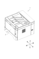
- FIG. 1 is a diagram showing an image forming apparatus having a cable housing member and a cable housing case according to the present embodiment
- FIG. FIG. 4 is a diagram showing the chassis of the cable housing member and the cable housing case
- FIG. 3 is an external perspective view showing the outline of the configuration of the cable storage member; It is a sectional view showing a section of a cable storage member.
- FIG. 10 is a cross-sectional view showing a cross-section of a cable housing member according to another embodiment
- FIG. 10 is a cross-sectional view showing a cross-section of a cable housing member according to another embodiment
- FIG. 3 shows a cable storage case having a cable storage member;
- FIG. 1 is a diagram showing an image forming apparatus 1 including a cable housing member 4 and a cable housing case 3 according to this embodiment.
- FIG. 2 is a diagram showing the chassis of the cable housing member 4 and the cable housing case 3. As shown in FIG.
- the image forming apparatus 1 reads an image on a sheet to obtain image data, or forms an image on the sheet. In addition, the image forming apparatus 1 transmits and receives image data.
- the image forming apparatus 1 is, for example, a scanner, a printer, a copier, a telephone, a printing machine, a facsimile machine, or a multifunction machine having these functions combined.
- the image forming apparatus 1 has a housing 2. As shown in FIG.
- the housing 2 may be made of resin or the like.
- the chassis shown in FIG. 2 is arranged inside the housing 2 .
- the chassis may be made of an aluminum alloy or the like.
- the chassis has a left chassis 20, a right chassis 21, and a center chassis 22.
- a chassis is formed by placing the center chassis 22 between the left chassis 20 and the right chassis 21 , connecting the left chassis 20 and the center chassis 22 , and connecting the right chassis 21 and the center chassis 22 .
- a cable storage member 4 and a cable storage case 3 are arranged on the chassis. In the cable storage member 4 and the cable storage case 3, cables are stored which will be explained in FIG.
- the chassis further includes an automatic feeding device, a conveying device, an image forming section, a fixing section, a discharge section, and a discharge tray.
- the automatic feeding device has a sheet tray and a pick-up roller.
- the sheet tray accommodates sheets.
- the pickup roller picks up the sheets stored in the sheet tray one by one and feeds them to the conveying device.
- the conveying device conveys the sheet fed from the automatic feeding device.
- the transport device has a transport path and transport rollers.
- the transport path is made of metal or resin, and extends from the automatic feeding device to the discharge section via the image forming section and fixing section.
- a plurality of transport rollers may be arranged on the transport path.
- the transport roller may be a combination of a driving roller and a driven roller.
- the image forming unit forms an image on a sheet using toner or ink.
- the image forming section includes a photoreceptor, a charging device, an exposure device, a developing device, a transfer device, a cleaning device, and a static elimination device.
- the image forming section has an ink cartridge, an ink tank, a pump, a head, nozzles, electrodes, and a transport belt.
- the fixing unit heats and presses the toner image developed on the sheet to fix the toner image on the sheet.
- the fixing section has, for example, a fixing roller, a heater, and a press roller.
- the image forming apparatus 1 is an inkjet printer, no fixing unit is required.
- the discharge unit discharges sheets to the outside of the housing 2 of the image forming apparatus 1 .
- the ejection section has an ejection roller and an ejection tray.
- the discharge roller discharges the sheet conveyed by the conveying device from the fixing device to the discharge tray.
- the discharge tray accommodates the discharged sheets.
- FIG. 3 is an external perspective view showing an outline of the configuration of the cable storage member 4.
- FIG. 4 is a sectional view showing a section of the cable storage member 4.
- FIG. 5 and 6 are cross-sectional views showing cross-sections of cable storage members 4 according to other embodiments.
- FIG. 7 shows a cable housing case 3 having a cable housing member 4.
- the cable storage member 4 holds and stores cables.
- the cables may include multiple types of cables.
- the cable housing member 4 may be made of resin or the like.
- the cable storage member 4 includes an upper storage wall 40 and a lower storage wall 41.
- the upper storage wall 40 and the lower storage wall 41 are formed to protrude in the lateral direction.
- the upper storage wall 40 and the lower storage wall 41 are arranged to face each other in the vertical direction. Cables are stored between the upper storage wall 40 and the lower storage wall 41 .
- the cable housing member 4 further includes a first upper separating member 402 or a first lower separating member 412.
- the first upper separation member 402 is formed in the upper storage wall 40 and divides the storage chamber 42 formed between the upper storage wall 40 and the lower storage wall 41 into the first storage chamber 420 and the second storage chamber 421 . To separate.
- the first lower separation member 412 is formed in the lower storage wall 41 and divides the storage chamber 42 formed between the upper storage wall 40 and the lower storage wall 41 into a first storage chamber 420 and a second storage chamber 421 . and separate.
- the first upper separation member 402 is a protrusion that is arranged on the upper storage wall 40 and formed to extend toward the lower storage wall 41 .
- the first lower separation member 412 is a protrusion that is disposed on the lower storage wall 41 and extends toward the upper storage wall 40 .
- the storage room 42 stores cables.
- the first storage chamber 420 and the second storage chamber 421 may store cables of different types.
- the first storage chamber 420 and the second storage chamber 421 are separated by the first upper separation member 402 or the first lower separation member 412, but are electrically connected.
- the cable stored in the first storage chamber 420 or the second storage chamber 421 can be gripped by the projection, and the cable can be held in the first storage chamber 420 or the second storage chamber 420. Dropping out of the storage chamber 421 can be suppressed.
- the cable stored in the first storage chamber 420 or the second storage chamber 421 can be gripped by the convex portion, and the cable can be held in the first storage chamber 420 or the second storage chamber 420. Dropping out of the second storage chamber 421 can be suppressed.
- a plurality of cables can be accommodated.
- the upper storage wall 40 is formed so as to project laterally from the upper rear end portion 401 to the upper front end portion 400 .
- the lower storage wall 41 is laterally protruded from a lower rear end portion 411 to a lower front end portion 410 . Therefore, the first storage chamber 420 and the second storage chamber 421 are arranged side by side in the horizontal direction. Therefore, the space in the vertical direction can be saved, which contributes to thinning of the image forming apparatus 1 in recent years.
- the first storage chamber 420 and the second storage chamber 421 can be formed with a simple configuration by forming the first upper separation member 402 and the first lower separation member 412 as convex portions.
- the vertical height of the first storage chamber 420 may be higher than the upper limit height of the second storage chamber 421 .
- a large-diameter or long-diameter cable may be stored in the first storage chamber 420 .
- the cable storage member 4 can hold and store a cable with a large diameter or a long diameter.
- the first storage chamber 420 may store an elliptical cable whose cross-sectional vertical diameter is longer than its horizontal diameter, or a rectangular cable with rounded corners.
- An example of an elliptical cable or a rounded rectangular cable is a SATA cable (Serial Advanced Technology Attachment).
- a SATA cable is, for example, a cable that connects a motherboard and an expansion card with a built-in drive inside the image forming apparatus 1 and transmits data.
- the cable storage member 4 can hold and store an elliptical cable such as a SATA cable or a rectangular cable with rounded corners.
- a circular cable with a circular cross section may be stored in the second storage chamber 421 .
- the second storage chamber 421 may store small and medium diameter or circular cables.
- USB cable Universal Serial Bus
- a USB cable is, for example, a cable that connects the image forming apparatus 1 and an external device.
- the cable storage member 4 can hold and store an elliptical cable such as a USB cable or a rectangular cable with rounded corners together with a SATA cable or the like.
- the upper storage wall 40 and the lower storage wall 41 forming the second storage chamber 421 are separated from each other to form an opening.
- the upper storage wall 40 and the lower storage wall 41 are made of resin or the like, and have openings so that cables can be easily inserted into and removed from the storage chamber 42 through the openings.
- the upper storage wall 40 may have an upper tip 400 extending toward the opening.
- the upper tip 400 may curve toward the lower storage wall 41 .
- the lower housing wall 41 may have a lower tip 410 extending toward the opening.
- the lower tip 410 may curve toward the upper storage wall 40 .
- the upper tip portion 400 or the lower storage wall 41 is curved, so that the cable stored in the storage chamber 42 can be prevented from falling off.
- FIG. 5 a cable storage member 4 according to another embodiment will be described with reference to FIGS. 5 and 6.
- FIG. 5 a cable storage member 4 according to another embodiment will be described with reference to FIGS. 5 and 6.
- the cable storage member 4 may include a second upper separating member 403 or a second lower separating member 413.
- the second upper separation member 403 is formed in the upper storage wall 40 and separates a second storage chamber 421 and a third storage chamber 422 formed on the opposite side of the second storage chamber 421 from the first storage chamber 420 . To separate.
- the second lower separation member 413 is formed in the lower storage wall 41 and includes a second storage chamber 421 and a third storage chamber 422 formed on the opposite side of the second storage chamber 421 from the first storage chamber 420 .
- the storage chamber 42 of the cable storage member 4 can be expanded in the lateral direction, and a plurality of cables with different shapes can be collectively gripped and stored. Furthermore, it is possible to further promote thinning of the image forming apparatus 1 .
- the upper storage wall 40 and the lower storage wall 41 forming the third storage chamber 422 are separated from each other to form an opening.
- the cable housing member 4 has an opening so that the cable can be easily inserted into and removed from the housing chamber 42 through the opening.
- the upper housing wall 40 also has an upper tip 400 extending toward the opening.
- the upper tip 400 may curve toward the lower storage wall 41 .
- the lower housing wall 41 has a lower tip 410 extending toward the opening.
- the lower tip 410 may curve toward the upper storage wall 40 .
- the upper tip portion 400 or the lower storage wall 41 is curved, so that the cable stored in the storage chamber 42 can be prevented from falling off.
- FIG. 7 shows a cable housing case 3 having a cable housing member 4.
- a plurality of cable storage members 4 are arranged in the cable storage case 3 .
- a plurality of cable housing members 4 adjacent to each other may be arranged at predetermined intervals.
- the cable storage member 4 may be attached to the cable storage case 3 .
- the cable storage member 4 may be integrally formed with the cable storage case 3 .
- the cable storage case 3 can be easily attached to the image forming apparatus 1 together with other substrates.
- the cable storage case 3 further includes rails.
- the rail connects the cable storage members 4 to each other.
- the rails are formed between cable housing members 4 arranged at predetermined intervals.
- the rail simply accommodates multiple cables.
- the rail is provided with a notch 5 adjacent to the cable housing member 4.
- the cable storage member 4 may be formed of resin or the like with flexibility as described above.
- the notch 5 adjacent to the cable storage member 4 in the rail By providing the notch 5 adjacent to the cable storage member 4 in the rail, the amount of the cable storage member 4 exposed in the lateral direction is increased. Therefore, it becomes easy to bend and becomes hard to be damaged.
- the user since the user can easily spread the upper storage wall 40 and the lower storage wall 41, the cable can be easily inserted into and removed from the storage chamber 42. ⁇
- the cable storage member 4 is arranged in the cable storage case 3, so that the cable storage member 4 and the cable storage case 3 can be easily attached to the image forming apparatus 1 when the image forming apparatus 1 is assembled. can be done.
- the notch portion 5 damage to the cable housing member 4 can be suppressed.
- the cable storage member 4 becomes more flexible and less likely to be damaged.
- the cable can be easily inserted into and removed from the storage chamber 42 .
- the present invention can be used in the fields of cable housing members and cable housing cases.
Landscapes
- Engineering & Computer Science (AREA)
- Microelectronics & Electronic Packaging (AREA)
- Physics & Mathematics (AREA)
- General Physics & Mathematics (AREA)
- Multimedia (AREA)
- Signal Processing (AREA)
- Electrophotography Configuration And Component (AREA)
- Insertion, Bundling And Securing Of Wires For Electric Apparatuses (AREA)
Priority Applications (1)
| Application Number | Priority Date | Filing Date | Title |
|---|---|---|---|
| JP2023556387A JP7750301B2 (ja) | 2021-10-28 | 2022-10-21 | ケーブル収納部材およびケーブル収納ケース |
Applications Claiming Priority (2)
| Application Number | Priority Date | Filing Date | Title |
|---|---|---|---|
| JP2021-176608 | 2021-10-28 | ||
| JP2021176608 | 2021-10-28 |
Publications (1)
| Publication Number | Publication Date |
|---|---|
| WO2023074549A1 true WO2023074549A1 (ja) | 2023-05-04 |
Family
ID=86159428
Family Applications (1)
| Application Number | Title | Priority Date | Filing Date |
|---|---|---|---|
| PCT/JP2022/039243 Ceased WO2023074549A1 (ja) | 2021-10-28 | 2022-10-21 | ケーブル収納部材およびケーブル収納ケース |
Country Status (2)
| Country | Link |
|---|---|
| JP (1) | JP7750301B2 (https=) |
| WO (1) | WO2023074549A1 (https=) |
Citations (7)
| Publication number | Priority date | Publication date | Assignee | Title |
|---|---|---|---|---|
| JPS6252975U (https=) * | 1985-09-24 | 1987-04-02 | ||
| JPH03296298A (ja) * | 1990-04-16 | 1991-12-26 | Hitachi Ltd | ケーブル固定機構 |
| JPH0758459A (ja) * | 1993-08-10 | 1995-03-03 | Fuji Electric Co Ltd | 信号装置の接続構造 |
| JP2008303984A (ja) * | 2007-06-07 | 2008-12-18 | Calsonic Kansei Corp | クリップ構造 |
| JP2013090397A (ja) * | 2011-10-14 | 2013-05-13 | Fujitsu Ltd | ケーブル保持具 |
| JP2014157981A (ja) * | 2013-02-18 | 2014-08-28 | Ricoh Co Ltd | ケーブル保持構造およびそれを備えた電気機器およびケーブル保持構造を用いたケーブル配線システム |
| JP2019011846A (ja) * | 2017-06-30 | 2019-01-24 | 本田技研工業株式会社 | クランプ構造 |
-
2022
- 2022-10-21 WO PCT/JP2022/039243 patent/WO2023074549A1/ja not_active Ceased
- 2022-10-21 JP JP2023556387A patent/JP7750301B2/ja active Active
Patent Citations (7)
| Publication number | Priority date | Publication date | Assignee | Title |
|---|---|---|---|---|
| JPS6252975U (https=) * | 1985-09-24 | 1987-04-02 | ||
| JPH03296298A (ja) * | 1990-04-16 | 1991-12-26 | Hitachi Ltd | ケーブル固定機構 |
| JPH0758459A (ja) * | 1993-08-10 | 1995-03-03 | Fuji Electric Co Ltd | 信号装置の接続構造 |
| JP2008303984A (ja) * | 2007-06-07 | 2008-12-18 | Calsonic Kansei Corp | クリップ構造 |
| JP2013090397A (ja) * | 2011-10-14 | 2013-05-13 | Fujitsu Ltd | ケーブル保持具 |
| JP2014157981A (ja) * | 2013-02-18 | 2014-08-28 | Ricoh Co Ltd | ケーブル保持構造およびそれを備えた電気機器およびケーブル保持構造を用いたケーブル配線システム |
| JP2019011846A (ja) * | 2017-06-30 | 2019-01-24 | 本田技研工業株式会社 | クランプ構造 |
Also Published As
| Publication number | Publication date |
|---|---|
| JPWO2023074549A1 (https=) | 2023-05-04 |
| JP7750301B2 (ja) | 2025-10-07 |
Similar Documents
| Publication | Publication Date | Title |
|---|---|---|
| US12174575B2 (en) | Image forming apparatus | |
| JP6673251B2 (ja) | 画像形成装置 | |
| US9740162B2 (en) | Image forming apparatus | |
| CN101135868B (zh) | 成像设备的介质供应装置 | |
| US9235159B2 (en) | Developer conveying device and image forming apparatus having a developer removing portion | |
| WO2023074549A1 (ja) | ケーブル収納部材およびケーブル収納ケース | |
| CN106200308B (zh) | 图像形成装置和可拆卸单元 | |
| US20050047842A1 (en) | Transporting apparatus, image forming apparatus and copier | |
| JP6332188B2 (ja) | 画像形成装置 | |
| JP2002023437A (ja) | 画像形成装置 | |
| CN109426106B (zh) | 图像形成设备 | |
| CN1970416B (zh) | 送纸盒 | |
| US9342023B1 (en) | Image forming apparatus | |
| JP2007248848A (ja) | 画像形成装置 | |
| JP4113243B2 (ja) | 自動原稿送り装置 | |
| CN120742634B (zh) | 显影盒及图像形成装置 | |
| KR100565083B1 (ko) | 화상형성장치 | |
| JP6669380B2 (ja) | シート積載装置及び画像形成装置 | |
| JP7081175B2 (ja) | 取付ユニット | |
| JP4452448B2 (ja) | 自動原稿送り装置 | |
| JP2008214039A (ja) | 静電気除去機構 | |
| KR100552508B1 (ko) | 소음방지용 캡을 구비한 화상형성장치 | |
| JP4406269B2 (ja) | 配線基板ユニットの装着構造 | |
| JP2021124702A (ja) | 画像形成装置 | |
| JP2001134161A (ja) | 画像形成装置 |
Legal Events
| Date | Code | Title | Description |
|---|---|---|---|
| 121 | Ep: the epo has been informed by wipo that ep was designated in this application |
Ref document number: 22886876 Country of ref document: EP Kind code of ref document: A1 |
|
| ENP | Entry into the national phase |
Ref document number: 2023556387 Country of ref document: JP Kind code of ref document: A |
|
| NENP | Non-entry into the national phase |
Ref country code: DE |
|
| 122 | Ep: pct application non-entry in european phase |
Ref document number: 22886876 Country of ref document: EP Kind code of ref document: A1 |