WO2023067802A1 - 駆動力制御装置、車両 - Google Patents
駆動力制御装置、車両 Download PDFInfo
- Publication number
- WO2023067802A1 WO2023067802A1 PCT/JP2021/039120 JP2021039120W WO2023067802A1 WO 2023067802 A1 WO2023067802 A1 WO 2023067802A1 JP 2021039120 W JP2021039120 W JP 2021039120W WO 2023067802 A1 WO2023067802 A1 WO 2023067802A1
- Authority
- WO
- WIPO (PCT)
- Prior art keywords
- torque
- vehicle
- command value
- driving force
- control device
- Prior art date
- Legal status (The legal status is an assumption and is not a legal conclusion. Google has not performed a legal analysis and makes no representation as to the accuracy of the status listed.)
- Ceased
Links
Images



Classifications
-
- B—PERFORMING OPERATIONS; TRANSPORTING
- B60—VEHICLES IN GENERAL
- B60W—CONJOINT CONTROL OF VEHICLE SUB-UNITS OF DIFFERENT TYPE OR DIFFERENT FUNCTION; CONTROL SYSTEMS SPECIALLY ADAPTED FOR HYBRID VEHICLES; ROAD VEHICLE DRIVE CONTROL SYSTEMS FOR PURPOSES NOT RELATED TO THE CONTROL OF A PARTICULAR SUB-UNIT
- B60W30/00—Purposes of road vehicle drive control systems not related to the control of a particular sub-unit, e.g. of systems using conjoint control of vehicle sub-units
- B60W30/18—Propelling the vehicle
- B60W30/188—Controlling power parameters of the driveline, e.g. determining the required power
-
- B—PERFORMING OPERATIONS; TRANSPORTING
- B60—VEHICLES IN GENERAL
- B60W—CONJOINT CONTROL OF VEHICLE SUB-UNITS OF DIFFERENT TYPE OR DIFFERENT FUNCTION; CONTROL SYSTEMS SPECIALLY ADAPTED FOR HYBRID VEHICLES; ROAD VEHICLE DRIVE CONTROL SYSTEMS FOR PURPOSES NOT RELATED TO THE CONTROL OF A PARTICULAR SUB-UNIT
- B60W30/00—Purposes of road vehicle drive control systems not related to the control of a particular sub-unit, e.g. of systems using conjoint control of vehicle sub-units
- B60W30/02—Control of vehicle driving stability
- B60W30/045—Improving turning performance
-
- B—PERFORMING OPERATIONS; TRANSPORTING
- B60—VEHICLES IN GENERAL
- B60L—PROPULSION OF ELECTRICALLY-PROPELLED VEHICLES; SUPPLYING ELECTRIC POWER FOR AUXILIARY EQUIPMENT OF ELECTRICALLY-PROPELLED VEHICLES; ELECTRODYNAMIC BRAKE SYSTEMS FOR VEHICLES IN GENERAL; MAGNETIC SUSPENSION OR LEVITATION FOR VEHICLES; MONITORING OPERATING VARIABLES OF ELECTRICALLY-PROPELLED VEHICLES; ELECTRIC SAFETY DEVICES FOR ELECTRICALLY-PROPELLED VEHICLES
- B60L9/00—Electric propulsion with power supply external to the vehicle
- B60L9/16—Electric propulsion with power supply external to the vehicle using AC induction motors
- B60L9/18—Electric propulsion with power supply external to the vehicle using AC induction motors fed from DC supply lines
-
- B—PERFORMING OPERATIONS; TRANSPORTING
- B60—VEHICLES IN GENERAL
- B60W—CONJOINT CONTROL OF VEHICLE SUB-UNITS OF DIFFERENT TYPE OR DIFFERENT FUNCTION; CONTROL SYSTEMS SPECIALLY ADAPTED FOR HYBRID VEHICLES; ROAD VEHICLE DRIVE CONTROL SYSTEMS FOR PURPOSES NOT RELATED TO THE CONTROL OF A PARTICULAR SUB-UNIT
- B60W40/00—Estimation or calculation of non-directly measurable driving parameters for road vehicle drive control systems not related to the control of a particular sub unit, e.g. by using mathematical models
- B60W40/02—Estimation or calculation of non-directly measurable driving parameters for road vehicle drive control systems not related to the control of a particular sub unit, e.g. by using mathematical models related to ambient conditions
- B60W40/06—Road conditions
-
- B—PERFORMING OPERATIONS; TRANSPORTING
- B60—VEHICLES IN GENERAL
- B60W—CONJOINT CONTROL OF VEHICLE SUB-UNITS OF DIFFERENT TYPE OR DIFFERENT FUNCTION; CONTROL SYSTEMS SPECIALLY ADAPTED FOR HYBRID VEHICLES; ROAD VEHICLE DRIVE CONTROL SYSTEMS FOR PURPOSES NOT RELATED TO THE CONTROL OF A PARTICULAR SUB-UNIT
- B60W50/00—Details of control systems for road vehicle drive control not related to the control of a particular sub-unit, e.g. process diagnostic or vehicle driver interfaces
- B60W50/08—Interaction between the driver and the control system
- B60W50/087—Interaction between the driver and the control system where the control system corrects or modifies a request from the driver
-
- B—PERFORMING OPERATIONS; TRANSPORTING
- B60—VEHICLES IN GENERAL
- B60W—CONJOINT CONTROL OF VEHICLE SUB-UNITS OF DIFFERENT TYPE OR DIFFERENT FUNCTION; CONTROL SYSTEMS SPECIALLY ADAPTED FOR HYBRID VEHICLES; ROAD VEHICLE DRIVE CONTROL SYSTEMS FOR PURPOSES NOT RELATED TO THE CONTROL OF A PARTICULAR SUB-UNIT
- B60W2510/00—Input parameters relating to a particular sub-units
- B60W2510/08—Electric propulsion units
- B60W2510/083—Torque
-
- B—PERFORMING OPERATIONS; TRANSPORTING
- B60—VEHICLES IN GENERAL
- B60W—CONJOINT CONTROL OF VEHICLE SUB-UNITS OF DIFFERENT TYPE OR DIFFERENT FUNCTION; CONTROL SYSTEMS SPECIALLY ADAPTED FOR HYBRID VEHICLES; ROAD VEHICLE DRIVE CONTROL SYSTEMS FOR PURPOSES NOT RELATED TO THE CONTROL OF A PARTICULAR SUB-UNIT
- B60W2510/00—Input parameters relating to a particular sub-units
- B60W2510/20—Steering systems
- B60W2510/207—Oversteer or understeer
-
- B—PERFORMING OPERATIONS; TRANSPORTING
- B60—VEHICLES IN GENERAL
- B60W—CONJOINT CONTROL OF VEHICLE SUB-UNITS OF DIFFERENT TYPE OR DIFFERENT FUNCTION; CONTROL SYSTEMS SPECIALLY ADAPTED FOR HYBRID VEHICLES; ROAD VEHICLE DRIVE CONTROL SYSTEMS FOR PURPOSES NOT RELATED TO THE CONTROL OF A PARTICULAR SUB-UNIT
- B60W2520/00—Input parameters relating to overall vehicle dynamics
- B60W2520/06—Direction of travel
-
- B—PERFORMING OPERATIONS; TRANSPORTING
- B60—VEHICLES IN GENERAL
- B60W—CONJOINT CONTROL OF VEHICLE SUB-UNITS OF DIFFERENT TYPE OR DIFFERENT FUNCTION; CONTROL SYSTEMS SPECIALLY ADAPTED FOR HYBRID VEHICLES; ROAD VEHICLE DRIVE CONTROL SYSTEMS FOR PURPOSES NOT RELATED TO THE CONTROL OF A PARTICULAR SUB-UNIT
- B60W2540/00—Input parameters relating to occupants
- B60W2540/18—Steering angle
-
- B—PERFORMING OPERATIONS; TRANSPORTING
- B60—VEHICLES IN GENERAL
- B60W—CONJOINT CONTROL OF VEHICLE SUB-UNITS OF DIFFERENT TYPE OR DIFFERENT FUNCTION; CONTROL SYSTEMS SPECIALLY ADAPTED FOR HYBRID VEHICLES; ROAD VEHICLE DRIVE CONTROL SYSTEMS FOR PURPOSES NOT RELATED TO THE CONTROL OF A PARTICULAR SUB-UNIT
- B60W2552/00—Input parameters relating to infrastructure
- B60W2552/30—Road curve radius
-
- B—PERFORMING OPERATIONS; TRANSPORTING
- B60—VEHICLES IN GENERAL
- B60W—CONJOINT CONTROL OF VEHICLE SUB-UNITS OF DIFFERENT TYPE OR DIFFERENT FUNCTION; CONTROL SYSTEMS SPECIALLY ADAPTED FOR HYBRID VEHICLES; ROAD VEHICLE DRIVE CONTROL SYSTEMS FOR PURPOSES NOT RELATED TO THE CONTROL OF A PARTICULAR SUB-UNIT
- B60W2720/00—Output or target parameters relating to overall vehicle dynamics
- B60W2720/40—Torque distribution
- B60W2720/406—Torque distribution between left and right wheel
-
- Y—GENERAL TAGGING OF NEW TECHNOLOGICAL DEVELOPMENTS; GENERAL TAGGING OF CROSS-SECTIONAL TECHNOLOGIES SPANNING OVER SEVERAL SECTIONS OF THE IPC; TECHNICAL SUBJECTS COVERED BY FORMER USPC CROSS-REFERENCE ART COLLECTIONS [XRACs] AND DIGESTS
- Y02—TECHNOLOGIES OR APPLICATIONS FOR MITIGATION OR ADAPTATION AGAINST CLIMATE CHANGE
- Y02T—CLIMATE CHANGE MITIGATION TECHNOLOGIES RELATED TO TRANSPORTATION
- Y02T10/00—Road transport of goods or passengers
- Y02T10/60—Other road transportation technologies with climate change mitigation effect
- Y02T10/72—Electric energy management in electromobility
Definitions
- the present invention relates to a driving force control device and a vehicle.
- a motor input/output coefficient correction device for a wheel independent drive electric vehicle comprising:
- Patent Document 1 assumes steering and there is room for improvement.
- a driving force control device is a driving force control device for a vehicle that includes a driving unit capable of driving left and right wheels independently, wherein torque is generated in each of the left and right wheels.
- a torque calculation unit that calculates a torque command value
- a traveling direction calculation unit that calculates a current traveling direction of the vehicle
- a target travel direction calculation unit that calculates a future target travel direction of the torque calculation unit calculates a calculation command value so as to bring the current travel direction closer to the target travel direction, and calculates the calculation command value It is output to the drive unit as the torque command value.
- a vehicle includes a drive unit capable of driving left and right wheels separately, and a torque command value that instructs the drive unit to generate torques for the left and right wheels respectively.
- a driving force control device that outputs a torque
- the driving force control device includes a torque calculation unit that calculates the torque command value; a traveling direction calculation unit that calculates the current traveling direction of the vehicle; a target travel direction calculation unit that calculates a future target travel direction of the vehicle using at least one of information on the road surface on which the vehicle travels and information on the external world of the vehicle, wherein the torque calculation unit calculates the current travel
- a calculation command value is calculated so as to bring the direction closer to the target traveling direction, and the calculation command value is output to the drive unit as the torque command value.
- the driving force of the left and right wheels can be controlled based on information on the road surface and the outside world.
- Configuration diagram of a vehicle in the first embodiment A diagram showing the definition of an angle Diagram showing the concept of driving force table Diagram showing an example of an override table Hardware configuration diagram of driving force control device Flowchart showing processing of the driving force control device Time chart showing the operation of the driving force control device Configuration diagram of a vehicle in the second embodiment
- FIG. 1 A first embodiment of the driving force control device will be described below with reference to FIGS. 1 to 7.
- FIG. 1 A first embodiment of the driving force control device will be described below with reference to FIGS. 1 to 7.
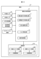
- FIG. 1 is a configuration diagram of a vehicle C including a driving force control device 10 according to the first embodiment.
- Vehicle C includes driving force control device 10 , external sensor 21 , internal sensor 22 , GPS receiver 23 , map information storage device 24 , navigation device 25 and drive unit 27 .
- the driving force control device 10 outputs a torque command value to the driving section 27 .
- the torque command value is a collection of torque information to be generated in the left wheel and the right wheel of the vehicle C, respectively.
- the driving force control device 10 includes, as its functions, a current traveling direction calculating section 11 , a target traveling direction calculating section 12 , a variation calculating section 13 , a torque calculating section 14 and an operation acquiring section 15 .
- a steering torque correspondence table 16 , a driving force table 18 , and an override table 19 are stored in the driving force control device 10 .
- the driving section 27 includes a driving device 28 and a driving force distribution device 29 .
- the driving device 28 is a power generation source that generates power for driving the vehicle C. As shown in FIG. Drive device 28 is, for example, an engine or a motor.
- the driving force distribution device 29 distributes the power generated by the driving device 28 to the left wheel and the right wheel of the vehicle C based on the torque command value output by the driving force control device 10 .
- the driving force distribution device 29 is, for example, an electronically controllable differential gear.
- the external sensor 21 is a sensor that senses the exterior of the vehicle C. External sensors 21 are, for example, cameras, laser range finders, LiDAR (light detection and ranging), and the like.
- the internal sensor 22 is a sensor that senses the interior of the vehicle C. As shown in FIG.
- the internal sensor 22 is, for example, a yaw rate sensor, a steering angle sensor, a depression amount sensor, and the like.
- the yaw rate sensor may be a gyro sensor capable of measuring a plurality of attitude angles including the yaw angle of the vehicle C.
- the steering angle sensor detects the steering angle of the steering wheel by the user.
- the depression amount sensor detects the amount of depression of the accelerator pedal and the brake pedal by the user.
- the GPS receiver 23 receives radio waves from multiple satellites that make up the satellite navigation system, and analyzes the signals contained in the radio waves to calculate the position of the vehicle, that is, the latitude and longitude.
- the GPS receiver 23 outputs the calculated latitude and longitude to the driving force control device 10 .
- the map information storage device 24 is a non-volatile storage device that stores map information including an area in which the vehicle C travels. Map information includes, for example, the latitude and longitude of nodes that are road edges and intersections, detailed shape information of links that connect nodes, and the like.
- the detailed shape information of the link includes the number of driving lanes, the distance between the driving lanes, the radius of curvature of the link, auxiliary points indicating multiple latitudes and longitudes on the link, and the like.
- the navigation device 25 calculates a route to the destination and outputs the route to the driving force control device 10 .
- the yaw angle of the vehicle C that is, the angle indicating the north, south, east, and west directions is called “vehicle angle ⁇ ".
- vehicle angle ⁇ is defined, for example, as an angle between the front direction of the vehicle C and the north, and takes a value of 0 degrees or more and less than 360 degrees.
- the current vehicle angle ⁇ of the vehicle C is called the “current vehicle angle ⁇ n”
- the future vehicle angle ⁇ of the vehicle C is called the "target vehicle angle ⁇ t”.
- the operation acquisition unit 15 acquires operation information of the accelerator pedal and the steering wheel by the user. In other words, the operation acquisition unit 15 acquires information (hereinafter referred to as “operation information”) regarding operation inputs for driving the vehicle C by the user.
- operation information includes at least information about the steering angle.
- the current traveling direction calculation unit 11 uses the outputs of the external sensor 21 and the internal sensor 22 to calculate the current vehicle angle ⁇ n. For the calculation of the current vehicle angle ⁇ n by the current traveling direction calculator 11, for example, the following methods can be used.
- the current traveling direction calculator 11 can calculate the current vehicle angle ⁇ n by integrating the output of the yaw rate sensor included in the internal sensor 22 . Further, the current traveling direction calculator 11 can combine the output of the external sensor 21 and the map information stored in the internal sensor 22 to calculate the current vehicle angle ⁇ n by map matching or the like. Furthermore, the current traveling direction calculator 11 can calculate the current vehicle angle ⁇ n using the outputs of the GPS receiver 23 at different times.
- the target traveling direction calculation unit 12 calculates the target vehicle angle ⁇ t using the outputs of the external sensor 21, the internal sensor 22, the GPS receiver 23, and the like.
- the calculation of the target vehicle angle ⁇ t by the target traveling direction calculation unit 12 does not use the operation information, especially the steering angle information.
- a specific method for calculating the target vehicle angle ⁇ t is not particularly limited, it can be calculated as follows, for example. First, based on the shape of the link on which the vehicle C is currently traveling, the current position of the vehicle C, the traveling direction of the vehicle C on the link, and the distance D, the target traveling direction calculation unit 12 calculates the future road of the vehicle C. Identify the location of For example, it is assumed here that vehicle C runs in the middle of the lane.
- the "moving direction on the link” here is information indicating whether the vehicle is traveling southward or northward on a link extending in the north-south direction, for example.
- the target traveling direction calculator 12 calculates an appropriate vehicle angle ⁇ of the vehicle C at that position, and sets this as the target vehicle angle ⁇ t.
- the appropriate own vehicle angle ⁇ is an angle at which the center line of the vehicle C is parallel to the nearest vehicle lane marking that forms the driving lane.
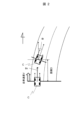
- FIG. 2 is a diagram showing definitions of angles in the present embodiment.
- the top is north.
- Two vehicles C are displayed in FIG. 2, the lower one showing the current position and the upper one showing the future position.
- the angle formed between the current traveling direction of the vehicle C and the north is the current vehicle angle ⁇ n
- the angle formed between the future traveling direction of the vehicle C and the north is the target vehicle angle ⁇ t.
- the change amount calculator 13 calculates the target slip angle ⁇ , which is the difference between the target vehicle angle ⁇ t and the current vehicle angle ⁇ n.
- the target slip angle ⁇ is defined as a value obtained by subtracting the current vehicle angle ⁇ n from the target vehicle angle ⁇ t.
- the torque of the left wheel of the vehicle C should be larger than the torque of the right wheel.
- the torque calculation unit 14 calculates a calculation command value and a user command value, and outputs one of them as a torque command value to the driving unit.
- the calculation command value is a torque command value calculated using the target direction of travel calculated by the target direction of travel calculator 12 . Considering that the calculation command value is the basis of the output from the torque calculation unit 14, it can be said that the torque calculation unit 14 determines whether or not to override the calculation command value with the user command value. However, the torque calculation unit 14 determines that there is no override when the user does not operate the steering wheel.
- the calculation command value and the user command value each include right wheel torque command value information and left wheel torque command value information.
- the torque command value for the right wheel and the torque command value for the left wheel may be indicated as individual numerical values, respectively, or may be indicated by the total value and ratio of both. , the sum of both and the difference between the two.
- the torque calculation unit 14 refers to the driving force table 18 and the override table 19 to calculate the calculation command value.
- the torque calculator 14 refers to the steering torque correspondence table 16 to calculate the user command value.
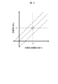
- the driving force table 18 is a pre-created lookup table that shows the correspondence between the target slip angle ⁇ and the target left-right driving force difference Td.
- the driving force table 18 is merely described as a lookup table for the sake of convenience. That is, it is not essential that the driving force table 18 is represented in tabular form, and may be represented in other forms, such as mathematical formulas. Therefore, the driving force table 18 can also be called "correspondence information between the angle difference and the torque difference" that indicates the correspondence between the target slip angle ⁇ and the target left-right driving force difference Td.
- FIG. 3 is a diagram showing the concept of the driving force table 18.
- FIG. FIG. 3 shows the correspondence between the target slip angle ⁇ and the target left-right driving force difference Td.
- the driving force table 18 the inclination of the road surface may be further taken into consideration.
- the correspondence between the target slip angle ⁇ and the target left-right driving force difference Td can be shifted as indicated by the dashed line in FIG. It is shown.
- the target left-right driving force difference Td corresponding to the target slip angle ⁇ is calculated in advance, for example, so that the yaw angle of the vehicle C changes by the same value as the target slip angle ⁇ after one control period of the driving force control device 10 .
- the steering torque correspondence table 16 is a pre-created lookup table that shows the correspondence between the steering angle operated by the user and the user command value.
- the steering torque correspondence table 16 is obtained, for example, by replacing the target slip angle ⁇ on the vertical axis in the driving force table 18 shown in FIG. 3 with the steering angle.
- the override table 19 is a table that is appropriately created by the torque calculation unit 14, and is a table that is referenced to determine whether or not to override the calculation command value with the user command value.
- the override table 19 is merely described as a table for convenience. In other words, it is not essential that the override table 19 is expressed in tabular form, but may be expressed in other forms, such as mathematical formulas. Therefore, the override table 19 can also be called "override judgment information".
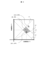
- FIG. 4 is a diagram showing an example of the override table 19.
- FIG. 4 two regions are shown with reference to the calculation command value calculated using the target traveling direction. These two areas are a hatched first area and a non-hatched second area.
- the first area is a non-overriding area and the second area is an overriding area.
- the first area is an area surrounded by dashed lines L1 to L4, which will be described later.
- the calculation command value is a torque command value calculated using the target traveling direction
- the user command value is a torque command value calculated using user operation information.
- the right wheel torque command value included in the calculated command value is referred to as a calculated right wheel torque SR
- the left wheel torque command value included in the calculated command value is referred to as a calculated right wheel torque SL.
- the right wheel torque command value included in the user command value is referred to as user right wheel torque UR
- the left wheel torque command value included in the user command value is referred to as user right wheel torque UR
- the ratio between the calculated left wheel torque SL and the calculated right wheel torque SR, more precisely, the absolute value of the calculated left wheel torque SL divided by the calculated right wheel torque SR is called the calculated torque ratio Rs.
- the ratio between the user left wheel torque UL and the user right wheel torque UR, more precisely, the absolute value of the value obtained by dividing the user left wheel torque UL by the user right wheel torque UR is called the user torque ratio Ru.
- the area between the dashed line L1 and the dashed line L2 is the area where the absolute value of the difference between the calculated torque ratio Rs and the user torque ratio Ru is smaller than the threshold ⁇ .
- the area between the dashed line L3 and the dashed line L4 represents the absolute difference between the sum of the calculated left wheel torque SL and the calculated right wheel torque SR and the sum of the user left wheel torque UL and the user right wheel torque UR. It is an area whose value is smaller than the threshold value ⁇ .
- square markers indicate calculation command values.
- the torque calculation unit 14 uses the calculated command value as the torque command value without overriding because the user command value is included in the first region. Output.
- the torque calculation unit 14 overrides the user command value because it is included in the second region, and outputs the user command value as the torque command value. do.
- the left and right wheels are steered based on the user's operation of the steering wheel regardless of the presence or absence of override.
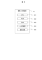
- FIG. 5 is a hardware configuration diagram of the driving force control device 10.
- the driving force control device 10 includes a CPU 801 as a central processing unit, a ROM 802 as a read-only storage device, a RAM 803 as a readable/writable storage device, and a communication device 805 .
- the CPU 801 expands the programs stored in the ROM 802 in the RAM 803 and executes them, thereby performing the various calculations described above.
- the driving force control device 10 is realized by FPGA (Field Programmable Gate Array), which is a rewritable logic circuit, and ASIC (Application Specific Integrated Circuit), which is an application-specific integrated circuit, instead of the combination of CPU 801, ROM 802, and RAM 803.
- FPGA Field Programmable Gate Array
- ASIC Application Specific Integrated Circuit
- driving force control device 10 may be realized by a combination of different configurations, for example, a combination of CPU 801, ROM 802, RAM 803 and an FPGA instead of the combination of CPU 801, ROM 802 and RAM 803.
- FIG. The communication device 805 communicates with other devices mounted on the vehicle C.
- FIG. 6 is a flowchart showing the processing of the driving force control device 10.
- the current traveling direction calculator 11 calculates the current vehicle angle ⁇ n.
- the current vehicle angle ⁇ n may be calculated using the output of the internal sensor 22 or the positional information of the vehicle C output by the GPS receiver 23 .
- the target travel direction calculator 12 determines the distance D to the target point.
- the distance D may be, for example, the distance traveled by the vehicle C at the current speed in a predetermined time period, or may be a preset fixed value.
- the predetermined time may be a preset fixed time, such as one second, or one control period of the driving force control device 10 .
- the target travel direction calculation unit 12 calculates the target vehicle angle ⁇ t.
- the target travel direction calculation unit 12 first calculates the future position of the vehicle C on the road based on the shape of the link on which the vehicle C is currently traveling, the current position of the vehicle C, the travel direction of the vehicle C, and the distance D. Identify.
- the target traveling direction calculator 12 calculates an appropriate vehicle angle ⁇ of the vehicle C at that position, and sets this as the target vehicle angle ⁇ t.
- the appropriate own vehicle angle ⁇ is an angle at which the center line of the vehicle C is parallel to the nearest lane marking.
- the change amount calculator 13 calculates the target slip angle ⁇ , which is the difference between the target vehicle angle ⁇ t and the current vehicle angle ⁇ n.
- the torque calculator 14 calculates the target left-right driving force difference Td according to the target slip angle ⁇ . Specifically, the torque calculator 14 refers to the driving force table 18 and reads the target left-right driving force difference Td corresponding to the target slip angle ⁇ . However, when the torque calculation unit 14 determines that the link on which the vehicle C is traveling has an inclination based on the information stored in the map information storage device 24, the target left/right drive is read according to the degree of inclination. Change the force difference Td.
- the target left-right driving force difference Td may be an integer value that is positive when the torque of the right wheel is larger than the torque of the left wheel. 3”.
- the target left-right driving force difference Td may be a combination of a sign specifying the larger one and a numerical value indicating the difference in magnitude.
- the target left-right driving force difference Td is expressed as "R10" or "L3". be done.
- the torque calculation unit 14 calculates the calculated left wheel torque SL and the calculated right wheel torque SR using the target driving force difference Td calculated in step S305.
- the total value of the torque command values for the left and right wheels is determined, for example, by the amount of depression of the accelerator pedal by the user and the legal speed of the link on which the vehicle C is traveling. For example, when the target driving force difference Td is "R10" and the total value of the torque command values for the left and right wheels is "50 N ⁇ m", the torque command value for the right wheel is "30 N ⁇ m" and the torque command value for the left wheel is "30 N ⁇ m". A value of "20 N ⁇ m" is calculated.
- the torque calculator 14 creates an override table 19.
- the override table 19 is created using the torque command value for the right wheel and the torque command value for the left wheel calculated in step S306.
- the torque calculation unit 14 identifies the user's steering amount included in the operation information, and refers to the steering torque correspondence table 16 to calculate the user left wheel torque UL and the user right wheel torque UR.
- the torque calculation unit 14 arranges the user command values calculated in step S308, that is, the user left wheel torque UL and the user right wheel torque UR, in the override table 19 created in step S307.
- step S310 the torque calculation unit 14 determines whether or not the user command value exists in the override region in the override table 19, that is, the second region.
- the torque calculation unit 14 proceeds to step S311, and when determining that the user command value does not exist within the override region, proceeds to step S312.
- step S311 the torque calculator 14 outputs the user command value as the torque command value, and ends the processing shown in FIG.
- step S312 the torque calculator 14 outputs the calculation command value as the torque command value, and ends the processing shown in FIG.
- FIG. 7 is a time chart showing the operation of the driving force control device 10.
- FIG. 7 the later time is indicated toward the right side of the drawing.
- FIG. 7 shows, from the top, changes over time in the vehicle angle, angular velocity, steering angle, and torque.
- the steering angle is always zero in the range shown in FIG. That is, the user does not operate the steering wheel.
- the vehicle C is traveling straight and the current vehicle angle ⁇ n is " ⁇ 0".
- the target traveling direction calculation unit 12 calculates that the target vehicle angle ⁇ t remains " ⁇ 0" and does not change, and both the calculated left wheel torque SL and the calculated right wheel torque SR are set to "T3".
- the target traveling direction calculation unit 12 calculates the target vehicle angle ⁇ t at time t13 as " ⁇ 1" from the information on the road surface on which the vehicle C is traveling. Then, the torque calculation unit 14 refers to the driving force table 18 to identify the target left-right driving force difference Td corresponding to the target slip angle " ⁇ 1- ⁇ 0", and determines the legal speed of the link on which the vehicle C travels.
- a calculated left wheel torque SL and a calculated right wheel torque SR are calculated using the sum of the torques calculated. In the example shown in FIG. 7, the calculated left wheel torque SL is calculated as "T4" and the calculated right wheel torque SR is calculated as "T2".
- the torque calculation unit 14 outputs this torque command value to the driving unit 27, so that the own vehicle angle and the angular velocity of the vehicle C increase little by little.
- the change amount calculation unit 13 calculates the future target vehicle angle ⁇ t to be " ⁇ 1", that is, the same value calculated at time t11. Since the target slip angle is zero and therefore the target left-right driving force difference Td is zero, the torque calculator 14 sets the calculated left wheel torque SL and the calculated right wheel torque SR to "T3". As a result, the angular velocity of the vehicle C becomes zero, and the vehicle angle remains " ⁇ 1". The above is the description of FIG. T1C.
- the driving force control device 10 is provided in a vehicle C having a drive unit 27 capable of driving left and right wheels independently.
- the driving force control device 10 includes a torque calculation unit 14 that individually calculates a calculated torque target value, which is torque to be generated in each of the left and right wheels, and a current traveling direction calculation unit 11 that calculates the current traveling direction of the vehicle C. and a target traveling direction calculation unit 12 that calculates a future target traveling direction of the vehicle C using at least one of information on the road surface on which the vehicle C travels and information on the external environment of the vehicle.
- the torque calculation unit 14 calculates the calculated torque target value so as to bring the current direction of travel closer to the target direction of travel. Therefore, the torque of the left and right wheels can be controlled regardless of the user's manipulation of the steering angle.
- the driving section 27 includes one driving device 28 and a driving force distribution device 29 capable of distributing the output of the electric motor to the left and right wheels. Therefore, the present invention can be implemented in a vehicle C having one drive device 28 .
- the torque calculator 14 calculates the calculated torque command value so that the current direction of travel is the target direction of travel. Therefore, the traveling direction of the vehicle C can be matched with the target traveling direction.
- the driving force control device 10 includes an operation acquisition unit 15 that acquires operation information that is information related to an operation input for the user to drive the vehicle and that includes at least information related to the steering angle. Based on the deviation between the user command value, which is the torque target value based on the operation information, and the calculation command value, which is the torque command value based on the target traveling direction, the torque calculation unit 14 overrides the calculation command value with the user command value. Decide whether or not Therefore, it is possible to realize control of the vehicle C that gives priority to the user's operation.
- the vehicle C does not have to accept the driving operation by the user. That is, the vehicle C may be a vehicle that only performs automatic driving. In this case, the driving force control device 10 does not need to include the operation acquisition section 15, and the torque calculation section 14 always outputs the calculation command value without judging whether to override. That is, the driving force control device 10 can omit the processing after step S307 in FIG. 6, and outputs the torque command value calculated in step S306.
- step S303 and S302 in FIG. 6 may be reversed so that the target vehicle angle ⁇ t is estimated after step S301, and then the distance D to the target point is determined.
- the vehicle angle ⁇ of the vehicle C traveling along the road is greater than or equal to a predetermined angle from the current vehicle angle ⁇ n. Identify the closest position to change.
- the torque calculator 14 overrides the calculation command value with the user command value in the following two cases. That is, in the first case, the absolute value of the difference between the calculated torque ratio Rs and the user torque ratio Ru is larger than the threshold ⁇ . In the second case, the absolute value of the difference between the sum of the calculated left wheel torque SL and the calculated right wheel torque SR and the sum of the user left wheel torque UL and the user right wheel torque UR is greater than the threshold value ⁇ . However, only one case may be overridden, and the difference may be evaluated instead of the ratio.
- Evaluating the difference instead of the ratio means that the absolute value of the difference between the calculated left wheel torque SL and the calculated right wheel torque SR and the difference between the user left wheel torque UL and the user right wheel torque UR is greater than the threshold value ⁇ . It evaluates whether it is large or not.
- the torque calculation unit 14 evaluates the difference between the ratio of the right wheel torque and the left wheel torque in the user command value and the ratio of the right wheel torque and the left wheel torque in the calculation command value, and determines the presence or absence of the override. . (6) The torque calculation unit 14 evaluates the difference between the right wheel torque and the left wheel torque in the user command value and the difference between the right wheel torque and the left wheel torque in the calculation command value, and determines the presence or absence of the override. .
- the target slip angle ⁇ may be easily calculated by using the radius of curvature of the link on which the vehicle C travels and the distance D. For example, if the radius of curvature of the link on which the vehicle C travels is "r" and the distance D calculated in step S302 is "d", the target slip angle ⁇ [deg] is 360*d/(2* ⁇ * r).
- the torque command value calculated by the torque calculator 14 is a constant value, and is set at that constant value until the calculation is performed again.
- the torque command value is changed at times t11 and t13, but there is no change at other times. Therefore, the angular velocity changed linearly, and the vehicle angle ⁇ changed quadratically.
- the torque command value does not have to be a constant value.
- the torque calculator 14 may control the torque so that the amount of change in the angle of the vehicle over time is constant, that is, the angular velocity is constant.
- the torque calculator 14 may set the value of the target left-right driving force difference Td by judging only whether the target slip angle ⁇ is positive, zero, or negative, instead of the numerical value of the target slip angle ⁇ itself.
- the value of the target left-right driving force difference Td is, for example, one of "+D", "0", and "-D”. That is, the torque calculator 14 may simply determine the value of the target left-right driving force difference Td so that the current direction of travel approaches the target direction of travel as much as possible.
- Embodiment- A second embodiment of the driving force control device will be described with reference to FIG.
- the same components as those in the first embodiment are assigned the same reference numerals, and differences are mainly described. Points that are not particularly described are the same as those in the first embodiment.
- This embodiment differs from the first embodiment mainly in that the vehicle includes a plurality of driving devices.
- FIG. 8 is a configuration diagram of a vehicle C1 including the driving force control device 10 according to the second embodiment.
- the vehicle C1 includes a driving section 27A instead of the driving section 27 in the first embodiment.
- the drive unit 27A includes a right wheel inverter device 28A, a right wheel electric motor 29A, a left wheel inverter device 28B, and a left wheel electric motor 29B.
- the drive unit 27A operates based on the torque command value output by the driving force control device 10.
- Right wheel electric motor 29A and left wheel electric motor 29B are, for example, in-wheel motors.
- the right wheel inverter device 28A supplies power to the right wheel electric motor 29A based on the torque command value for the right wheel included in the torque command value.
- the left wheel inverter device 28B supplies power to the left wheel electric motor 29B based on the torque command value for the left wheel included in the torque command value.
- the configuration of the driving force control device 10 is the same as that of the first embodiment, so the description is omitted. That is, the present embodiment differs from the first embodiment in the configuration for driving the vehicle C1.
- the drive unit 27A includes a left wheel electric motor 29B that drives the left wheel and a right wheel electric motor 29A that drives the right wheel and is different from the left wheel electric motor 29B. Therefore, the present invention can be implemented in the vehicle C1 including electric motors for driving the left and right wheels.
- the configuration of the functional blocks is merely an example. Some functional configurations shown as separate functional blocks may be configured integrally, or a configuration represented by one functional block diagram may be divided into two or more functions. Further, a configuration may be adopted in which part of the functions of each functional block is provided in another functional block.
- the programs are stored in the ROM 802 in each of the embodiments and modifications described above, the programs may be stored in a non-volatile memory (not shown).
- the driving force control device 10 may include an input/output interface (not shown), and the program may be read from another device via a medium that can be used by the input/output interface and the driving force control device 10 when necessary.
- the medium refers to, for example, a storage medium that can be attached to and detached from an input/output interface, or a communication medium, that is, a wired, wireless, or optical network, or a carrier wave or digital signal that propagates through the network.
- part or all of the functions realized by the program may be realized by a hardware circuit or FPGA.
Landscapes
- Engineering & Computer Science (AREA)
- Automation & Control Theory (AREA)
- Transportation (AREA)
- Mechanical Engineering (AREA)
- Human Computer Interaction (AREA)
- Physics & Mathematics (AREA)
- Mathematical Physics (AREA)
- Life Sciences & Earth Sciences (AREA)
- Sustainable Development (AREA)
- Sustainable Energy (AREA)
- Power Engineering (AREA)
- Electric Propulsion And Braking For Vehicles (AREA)
Abstract
Description
本発明の第2の態様による車両は、左輪および右輪を個別に駆動可能な駆動部と、前記駆動部に対して前記左輪および前記右輪のそれぞれに生じさせるトルクを指示するトルク指令値を出力する駆動力制御装置とを備える車両であって、前記駆動力制御装置は、前記トルク指令値を算出するトルク算出部と、前記車両の現在進行方向を算出する進行方向算出部と、前記車両が走行する路面の情報、および前記車両の外界情報のうち少なくとも一方を用いて前記車両の将来の目標進行方向を算出する目標進行方向算出部と、を備え、前記トルク算出部は、前記現在進行方向を前記目標進行方向へ近づけるように演算指令値を算出し、前記演算指令値を前記トルク指令値として前記駆動部に出力する。
以下、図1~図7を参照して、駆動力制御装置の第1の実施の形態を説明する。
(1)駆動力制御装置10は、左輪および右輪を個別に駆動可能な駆動部27を備える車両Cに備えられる。駆動力制御装置10は、左輪および右輪のそれぞれに生じさせるトルクである演算トルク目標値を個別に算出するトルク算出部14と、車両Cの現在の進行方向を算出する現在進行方向算出部11と、車両Cが走行する路面の情報、および車両の外界情報のうち少なくとも一方を用いて、車両Cの将来の目標進行方向を算出する目標進行方向算出部12と、を備える。トルク算出部14は、現在進行方向を目標進行方向へ近づけるように演算トルク目標値を算出する。そのため、ユーザによる操舵角の操作によらず、左右輪のトルクを制御できる。
車両Cはユーザによる運転操作を受け付けなくてもよい。すなわち車両Cは自動運転のみを行う車両であってもよい。この場合には、駆動力制御装置10は操作取得部15を備えなくてよく、トルク算出部14はオーバーライドの判断をすることなく常に演算指令値を出力する。すなわち駆動力制御装置10は、図6におけるステップS307以降の処理が省略でき、ステップS306において算出したトルク指令値を出力する。
図6のステップS303とS302の順番を入れ替えて、ステップS301の次に目標自車角度θtの推定を実行し、その次に目標地点までの距離Dの決定を行ってもよい。この場合はたとえば、車両Cが現在走行しているリンクの形状および車両Cの現在の位置に基づき、道路に沿って走行する車両Cの自車角度θが現在自車角度θnから所定の角度以上変化する最も近い位置を特定する。
トルク算出部14は、上述した第1の実施の形態では、次の2つの場合に演算指令値をユーザ指令値でオーバーライドした。すなわち1つ目の場合は、演算トルク比率Rsとユーザトルク比率Ruとの差の絶対値が閾値αよりも大きい場合である。2つ目の場合は、演算左輪トルクSLと演算右輪トルクSRとの和とユーザ左輪トルクULとユーザ右輪トルクURとの和との差の絶対値が閾値βよりも大きい場合である。しかし、いずれか一方の場合のみオーバーライドしてもよいし、比率の代わりに差を評価してもよい。比率の代わりに差を評価するとは、演算左輪トルクSLと演算右輪トルクSRとの差と、ユーザ左輪トルクULとユーザ右輪トルクURとの差、との差の絶対値が閾値γよりも大きいか否かを評価するものである。
(5)トルク算出部14は、ユーザ指令値における右輪トルクと左輪トルクとの比率、および演算指令値における右輪トルクと左輪トルクとの比率、の乖離を評価してオーバーライドの有無を決定する。
(6)トルク算出部14は、ユーザ指令値における右輪トルクと左輪トルクとの差、および演算指令値における右輪トルクと左輪トルクとの差、の乖離を評価してオーバーライドの有無を決定する。
車両Cが走行するリンクの曲率半径と距離Dを用いることで、簡易に目標滑り角ωを算出してもよい。たとえば車両Cが走行するリンクの曲率半径を「r」、ステップS302において算出された距離Dを「d」と置く場合に、目標滑り角ω[deg]は、360*d/(2*π*r)として算出される。
上述した第1の実施の形態では、トルク算出部14が算出するトルク指令値はある一定値であり、改めて計算がされるまではその一定値のままに設定された。たとえば図7では、時刻t11および時刻t13にトルク指令値が変更されるが他の時刻には変化がなかった。そのため、角速度は直線的に変化し、自車角度θは二次関数的に変化した。しかしトルク指令値は一定値でなくてもよく、たとえばトルク算出部14は自車角度の時間変化量が一定、すなわち角速度が一定となるようにトルクを制御してもよい。
トルク算出部14は、目標滑り角ωの数値そのものではなく、正、ゼロ、負のいずれかであるかだけを判断して、目標左右駆動力差Tdの値を設定してもよい。この場合には目標左右駆動力差Tdの値はたとえば、「+D」、「0」、「-D」のいずれかである。すなわちトルク算出部14は、現在進行方向が目標進行方向に少しでも近づくように目標左右駆動力差Tdの値を簡易に決定してもよい。
図8を参照して、駆動力制御装置の第2の実施の形態を説明する。以下の説明では、第1の実施の形態と同じ構成要素には同じ符号を付して相違点を主に説明する。特に説明しない点については、第1の実施の形態と同じである。本実施の形態では、主に、車両が複数の駆動装置を備える点で、第1の実施の形態と異なる。
(7)駆動部27Aは、左輪を駆動する左輪電動機29Bと、右輪を駆動し左輪電動機29Bとは異なる右輪電動機29Aとを備える。そのため、左右輪のそれぞれを駆動させる電動機を備える車両C1において本発明を実施できる。
11…現在進行方向算出部
12…目標進行方向算出部
14…トルク算出部
15…操作取得部
27、27A…駆動部
28…駆動装置
28A…右輪インバータ装置
28B…左輪インバータ装置
29…駆動力分配装置
29A…右輪電動機
29B…左輪電動機
Claims (10)
- 左輪および右輪を個別に駆動可能な駆動部を備える車両の駆動力制御装置において、
前記左輪および前記右輪のそれぞれに生じさせるトルクであるトルク指令値を算出するトルク算出部と、
前記車両の現在進行方向を算出する進行方向算出部と、
前記車両が走行する路面の情報、および前記車両の外界情報のうち少なくとも一方を用いて前記車両の将来の目標進行方向を算出する目標進行方向算出部と、を備え、
前記トルク算出部は、前記現在進行方向を前記目標進行方向へ近づけるように演算指令値を算出し、前記演算指令値を前記トルク指令値として前記駆動部に出力する、駆動力制御装置。 - 請求項1に記載の駆動力制御装置において、
前記駆動部は、少なくとも1つの駆動装置と、前記駆動装置の出力を前記左輪および前記右輪に配分可能な差動装置を備える、駆動力制御装置。 - 請求項1に記載の駆動力制御装置において、
前記駆動部は、前記左輪を駆動する左輪電動機と、前記右輪を駆動し前記左輪電動機とは異なる右輪電動機とを備える、駆動力制御装置。 - 請求項1に記載の駆動力制御装置において、
前記トルク算出部は、前記現在進行方向が前記目標進行方向となるように前記演算指令値を算出する、駆動力制御装置。 - 請求項1に記載の駆動力制御装置において、
ユーザが前記車両を運転するための操作入力に関する情報であり少なくとも操舵角に関する情報を含む操作情報を取得する操作取得部をさらに備え、
前記トルク算出部は、前記操作情報に基づく前記トルク指令値であるユーザ指令値と、前記目標進行方向に基づく前記トルク指令値である前記演算指令値との乖離に基づき、前記演算指令値を前記ユーザ指令値でオーバーライドするか否かを決定する、駆動力制御装置。 - 請求項5に記載の駆動力制御装置において、
前記トルク算出部は、前記ユーザ指令値における右輪トルクと左輪トルクとの比率、および前記演算指令値における右輪トルクと左輪トルクとの比率、の乖離を評価する、駆動力制御装置。 - 請求項5に記載の駆動力制御装置において、
前記トルク算出部は、前記ユーザ指令値における右輪トルクと左輪トルクとの差、および前記演算指令値における右輪トルクと左輪トルクとの差、の乖離を評価する、駆動力制御装置。 - 左輪および右輪を個別に駆動可能な駆動部と、
前記駆動部に対して前記左輪および前記右輪のそれぞれに生じさせるトルクを指示するトルク指令値を出力する駆動力制御装置とを備える車両であって、
前記駆動力制御装置は、
前記トルク指令値を算出するトルク算出部と、
前記車両の現在進行方向を算出する進行方向算出部と、
前記車両が走行する路面の情報、および前記車両の外界情報のうち少なくとも一方を用いて前記車両の将来の目標進行方向を算出する目標進行方向算出部と、を備え、
前記トルク算出部は、前記現在進行方向を前記目標進行方向へ近づけるように演算指令値を算出し、前記演算指令値を前記トルク指令値として前記駆動部に出力する、車両。 - 請求項8に記載の車両において、
前記駆動部は、少なくとも1つの駆動装置と、前記駆動装置の出力を前記左輪および前記右輪に配分可能な差動装置を備える、車両。 - 請求項8に記載の車両において、
前記駆動部は、前記左輪を駆動する左輪電動機と、前記右輪を駆動し前記左輪電動機とは異なる右輪電動機とを備える、車両。
Priority Applications (4)
| Application Number | Priority Date | Filing Date | Title |
|---|---|---|---|
| JP2023554213A JP7789794B2 (ja) | 2021-10-22 | 2021-10-22 | 駆動力制御装置、車両 |
| US18/702,961 US12691884B2 (en) | 2021-10-22 | 2021-10-22 | Driving force control device and vehicle |
| PCT/JP2021/039120 WO2023067802A1 (ja) | 2021-10-22 | 2021-10-22 | 駆動力制御装置、車両 |
| CN202180103523.7A CN118139759A (zh) | 2021-10-22 | 2021-10-22 | 驱动力控制装置和车辆 |
Applications Claiming Priority (1)
| Application Number | Priority Date | Filing Date | Title |
|---|---|---|---|
| PCT/JP2021/039120 WO2023067802A1 (ja) | 2021-10-22 | 2021-10-22 | 駆動力制御装置、車両 |
Publications (1)
| Publication Number | Publication Date |
|---|---|
| WO2023067802A1 true WO2023067802A1 (ja) | 2023-04-27 |
Family
ID=86058068
Family Applications (1)
| Application Number | Title | Priority Date | Filing Date |
|---|---|---|---|
| PCT/JP2021/039120 Ceased WO2023067802A1 (ja) | 2021-10-22 | 2021-10-22 | 駆動力制御装置、車両 |
Country Status (4)
| Country | Link |
|---|---|
| US (1) | US12691884B2 (ja) |
| JP (1) | JP7789794B2 (ja) |
| CN (1) | CN118139759A (ja) |
| WO (1) | WO2023067802A1 (ja) |
Citations (3)
| Publication number | Priority date | Publication date | Assignee | Title |
|---|---|---|---|---|
| JP2016199114A (ja) * | 2015-04-08 | 2016-12-01 | トヨタ自動車株式会社 | 車両の運転支援制御装置 |
| JP2017065323A (ja) * | 2015-09-28 | 2017-04-06 | トヨタ自動車株式会社 | 車両の運転支援制御装置 |
| JP2018167733A (ja) * | 2017-03-30 | 2018-11-01 | 株式会社Subaru | 車両の走行制御装置 |
Family Cites Families (12)
| Publication number | Priority date | Publication date | Assignee | Title |
|---|---|---|---|---|
| US6909959B2 (en) * | 2003-03-07 | 2005-06-21 | Stephen James Hallowell | Torque distribution systems and methods for wheeled vehicles |
| JP2005184911A (ja) | 2003-12-17 | 2005-07-07 | Nissan Motor Co Ltd | 車輪独立駆動電気自動車のモータ入出力係数修正装置 |
| EP1619063B1 (en) * | 2004-07-21 | 2009-10-14 | Nissan Motor Company, Limited | Motor torque control apparatus and method for automotive vehicle |
| US7739005B1 (en) * | 2009-02-26 | 2010-06-15 | Tesla Motors, Inc. | Control system for an all-wheel drive electric vehicle |
| JP5143103B2 (ja) * | 2009-09-30 | 2013-02-13 | 日立オートモティブシステムズ株式会社 | 車両の運動制御装置 |
| JP6236672B2 (ja) * | 2013-09-26 | 2017-11-29 | 日立オートモティブシステムズ株式会社 | 電動車両の制御装置 |
| JP6573643B2 (ja) * | 2017-03-27 | 2019-09-11 | 株式会社Subaru | 車両の走行制御装置 |
| JP6642517B2 (ja) * | 2017-05-16 | 2020-02-05 | トヨタ自動車株式会社 | 駆動力制御装置 |
| JP7076303B2 (ja) * | 2018-06-28 | 2022-05-27 | 本田技研工業株式会社 | 車両制御装置 |
| US11618436B2 (en) * | 2019-11-12 | 2023-04-04 | Subaru Corporation | Controlling driving force distribution ratio in response to prediction of oversteer |
| CN115151475B (zh) * | 2020-02-27 | 2024-03-08 | 三菱电机株式会社 | 转向控制装置 |
| US11628827B2 (en) * | 2021-01-19 | 2023-04-18 | Denso Ten Limited | Vehicle control device and control method |
-
2021
- 2021-10-22 US US18/702,961 patent/US12691884B2/en active Active
- 2021-10-22 WO PCT/JP2021/039120 patent/WO2023067802A1/ja not_active Ceased
- 2021-10-22 CN CN202180103523.7A patent/CN118139759A/zh active Pending
- 2021-10-22 JP JP2023554213A patent/JP7789794B2/ja active Active
Patent Citations (3)
| Publication number | Priority date | Publication date | Assignee | Title |
|---|---|---|---|---|
| JP2016199114A (ja) * | 2015-04-08 | 2016-12-01 | トヨタ自動車株式会社 | 車両の運転支援制御装置 |
| JP2017065323A (ja) * | 2015-09-28 | 2017-04-06 | トヨタ自動車株式会社 | 車両の運転支援制御装置 |
| JP2018167733A (ja) * | 2017-03-30 | 2018-11-01 | 株式会社Subaru | 車両の走行制御装置 |
Also Published As
| Publication number | Publication date |
|---|---|
| JP7789794B2 (ja) | 2025-12-22 |
| JPWO2023067802A1 (ja) | 2023-04-27 |
| US20240409100A1 (en) | 2024-12-12 |
| US12691884B2 (en) | 2026-07-28 |
| CN118139759A (zh) | 2024-06-04 |
Similar Documents
| Publication | Publication Date | Title |
|---|---|---|
| US12208822B2 (en) | Trajectory determination for four-wheel steering | |
| US11345400B2 (en) | Trajectory tracking with four-wheel steering and steering limits | |
| CN106476883B (zh) | 车辆的行驶控制装置 | |
| EP3659897B1 (en) | Steering determination device and autonomous driving system | |
| US11414127B2 (en) | Trajectory tracking with four-wheel steering | |
| US9244462B2 (en) | Vehicle trajectory planning for autonomous vehicles | |
| JP6315107B2 (ja) | 目標経路生成装置および走行制御装置 | |
| US11377112B2 (en) | Low-speed, backward driving vehicle controller design | |
| JP7185511B2 (ja) | 車両の走行制御装置 | |
| JP6618653B1 (ja) | 走行経路生成装置および車両制御装置 | |
| JP7752646B2 (ja) | 四輪ステアリング | |
| CN114364592A (zh) | 用于自动驾驶车辆的轨迹形状生成的方法和装置 | |
| CN115384491A (zh) | 自动车辆的可定制车道偏置 | |
| US12325409B2 (en) | Map-based braking | |
| JP2003276628A (ja) | 自動操舵装置 | |
| JP6898636B2 (ja) | 車両の走行制御装置 | |
| US20230030368A1 (en) | Vehicle control device | |
| WO2016110730A1 (ja) | 目標車速生成装置および走行制御装置 | |
| JP7789794B2 (ja) | 駆動力制御装置、車両 | |
| CN119895231A (zh) | 用于对自动驾驶的车辆的规划路线的方法和系统 | |
| JP5510379B2 (ja) | 車両および車両制御プログラム | |
| JP6496588B2 (ja) | 車両挙動制御装置 | |
| JP7631818B2 (ja) | 自動走行制御方法および自動走行制御装置 |
Legal Events
| Date | Code | Title | Description |
|---|---|---|---|
| 121 | Ep: the epo has been informed by wipo that ep was designated in this application |
Ref document number: 21961451 Country of ref document: EP Kind code of ref document: A1 |
|
| WWE | Wipo information: entry into national phase |
Ref document number: 18702961 Country of ref document: US Ref document number: 202180103523.7 Country of ref document: CN |
|
| NENP | Non-entry into the national phase |
Ref country code: DE |
|
| WWE | Wipo information: entry into national phase |
Ref document number: 2023554213 Country of ref document: JP |
|
| 122 | Ep: pct application non-entry in european phase |
Ref document number: 21961451 Country of ref document: EP Kind code of ref document: A1 |
|
| WWG | Wipo information: grant in national office |
Ref document number: 18702961 Country of ref document: US |