WO2023062966A1 - 通気システム - Google Patents
通気システム Download PDFInfo
- Publication number
- WO2023062966A1 WO2023062966A1 PCT/JP2022/033290 JP2022033290W WO2023062966A1 WO 2023062966 A1 WO2023062966 A1 WO 2023062966A1 JP 2022033290 W JP2022033290 W JP 2022033290W WO 2023062966 A1 WO2023062966 A1 WO 2023062966A1
- Authority
- WO
- WIPO (PCT)
- Prior art keywords
- housing
- opening
- air passage
- connection portion
- connecting portion
- Prior art date
- Legal status (The legal status is an assumption and is not a legal conclusion. Google has not performed a legal analysis and makes no representation as to the accuracy of the status listed.)
- Ceased
Links
Images









Classifications
-
- G—PHYSICS
- G10—MUSICAL INSTRUMENTS; ACOUSTICS
- G10K—SOUND-PRODUCING DEVICES; METHODS OR DEVICES FOR PROTECTING AGAINST, OR FOR DAMPING, NOISE OR OTHER ACOUSTIC WAVES IN GENERAL; ACOUSTICS NOT OTHERWISE PROVIDED FOR
- G10K11/00—Methods or devices for transmitting, conducting or directing sound in general; Methods or devices for protecting against, or for damping, noise or other acoustic waves in general
- G10K11/16—Methods or devices for protecting against, or for damping, noise or other acoustic waves in general
- G10K11/161—Methods or devices for protecting against, or for damping, noise or other acoustic waves in general in systems with fluid flow
-
- F—MECHANICAL ENGINEERING; LIGHTING; HEATING; WEAPONS; BLASTING
- F16—ENGINEERING ELEMENTS AND UNITS; GENERAL MEASURES FOR PRODUCING AND MAINTAINING EFFECTIVE FUNCTIONING OF MACHINES OR INSTALLATIONS; THERMAL INSULATION IN GENERAL
- F16L—PIPES; JOINTS OR FITTINGS FOR PIPES; SUPPORTS FOR PIPES, CABLES OR PROTECTIVE TUBING; MEANS FOR THERMAL INSULATION IN GENERAL
- F16L33/00—Arrangements for connecting hoses to rigid members; Rigid hose-connectors, i.e. single members engaging both hoses
- F16L33/30—Arrangements for connecting hoses to rigid members; Rigid hose-connectors, i.e. single members engaging both hoses comprising parts inside the hoses only
-
- F—MECHANICAL ENGINEERING; LIGHTING; HEATING; WEAPONS; BLASTING
- F16—ENGINEERING ELEMENTS AND UNITS; GENERAL MEASURES FOR PRODUCING AND MAINTAINING EFFECTIVE FUNCTIONING OF MACHINES OR INSTALLATIONS; THERMAL INSULATION IN GENERAL
- F16L—PIPES; JOINTS OR FITTINGS FOR PIPES; SUPPORTS FOR PIPES, CABLES OR PROTECTIVE TUBING; MEANS FOR THERMAL INSULATION IN GENERAL
- F16L55/00—Devices or appurtenances for use in, or in connection with, pipes or pipe systems
- F16L55/02—Energy absorbers; Noise absorbers
- F16L55/033—Noise absorbers
- F16L55/0336—Noise absorbers by means of sound-absorbing materials
-
- F—MECHANICAL ENGINEERING; LIGHTING; HEATING; WEAPONS; BLASTING
- F24—HEATING; RANGES; VENTILATING
- F24F—AIR-CONDITIONING; AIR-HUMIDIFICATION; VENTILATION; USE OF AIR CURRENTS FOR SCREENING
- F24F13/00—Details common to, or for air-conditioning, air-humidification, ventilation or use of air currents for screening
- F24F13/02—Ducting arrangements
-
- F—MECHANICAL ENGINEERING; LIGHTING; HEATING; WEAPONS; BLASTING
- F24—HEATING; RANGES; VENTILATING
- F24F—AIR-CONDITIONING; AIR-HUMIDIFICATION; VENTILATION; USE OF AIR CURRENTS FOR SCREENING
- F24F13/00—Details common to, or for air-conditioning, air-humidification, ventilation or use of air currents for screening
- F24F13/24—Means for preventing or suppressing noise
-
- G—PHYSICS
- G10—MUSICAL INSTRUMENTS; ACOUSTICS
- G10K—SOUND-PRODUCING DEVICES; METHODS OR DEVICES FOR PROTECTING AGAINST, OR FOR DAMPING, NOISE OR OTHER ACOUSTIC WAVES IN GENERAL; ACOUSTICS NOT OTHERWISE PROVIDED FOR
- G10K11/00—Methods or devices for transmitting, conducting or directing sound in general; Methods or devices for protecting against, or for damping, noise or other acoustic waves in general
- G10K11/16—Methods or devices for protecting against, or for damping, noise or other acoustic waves in general
-
- G—PHYSICS
- G10—MUSICAL INSTRUMENTS; ACOUSTICS
- G10K—SOUND-PRODUCING DEVICES; METHODS OR DEVICES FOR PROTECTING AGAINST, OR FOR DAMPING, NOISE OR OTHER ACOUSTIC WAVES IN GENERAL; ACOUSTICS NOT OTHERWISE PROVIDED FOR
- G10K11/00—Methods or devices for transmitting, conducting or directing sound in general; Methods or devices for protecting against, or for damping, noise or other acoustic waves in general
- G10K11/16—Methods or devices for protecting against, or for damping, noise or other acoustic waves in general
- G10K11/172—Methods or devices for protecting against, or for damping, noise or other acoustic waves in general using resonance effects
-
- F—MECHANICAL ENGINEERING; LIGHTING; HEATING; WEAPONS; BLASTING
- F24—HEATING; RANGES; VENTILATING
- F24F—AIR-CONDITIONING; AIR-HUMIDIFICATION; VENTILATION; USE OF AIR CURRENTS FOR SCREENING
- F24F13/00—Details common to, or for air-conditioning, air-humidification, ventilation or use of air currents for screening
- F24F13/24—Means for preventing or suppressing noise
- F24F2013/242—Sound-absorbing material
Definitions
- the present invention relates to a ventilation system in which a silencer is arranged in the middle of the ventilation path.
- a box-shaped extension is provided in the middle of the ventilation path, and this extension constitutes a silencer (see Fig. 5).
- this extension there are arranged an air passage extending from the entrance to the exit of the extension (hereinafter referred to as an inner air passage) and a sound absorbing member surrounding the inner air passage.
- an inner air passage extending from the entrance to the exit of the extension
- a sound absorbing member surrounding the inner air passage.
- the air passage narrows in the middle of the inner air passage and widens downstream (see FIG. 5).
- the flow velocity of the wind (air current) flowing through the air passage is increased in the inner air passage, so that the effect of the sound absorbing member is more likely to be exhibited, resulting in improved noise reduction.
- the cross-sectional area of the inner air passage is gradually changed at the inlet side end and the outlet side end of the inner air passage. Specifically, the cross-sectional area decreases with distance from the inlet or outlet. In other words, the cross-sectional area of the inner air passage gradually increases as it approaches the entrance or exit.
- the thickness of the sound absorbing member surrounding the inner air passage changes accordingly. Therefore, in the muffler described in Patent Document 1, the thickness of the sound absorbing member is thin near the entrance and exit of the extended portion. Reducing the thickness of the sound absorbing member in this way can reduce the sound deadening effect in the muffler.
- the silencer disclosed in Patent Document 1 if the thickness of the sound absorbing member is ensured in the vicinity of the entrance and exit of the extended portion, the overall size of the silencer increases. As a result, it is necessary to ensure a wider installation space for the muffler.
- the present invention has been made in view of the above circumstances, and solves the problems of the prior art. To provide a ventilation system capable of suppressing pressure loss at
- the ventilation system of the present invention has the following configuration.
- a housing having an air passage and a silencer disposed in the middle of the air passage, the silencer having an entrance opening and an exit opening, and extending from the entrance opening to the exit opening of the air passage.
- An upstream side air passage on the upstream side of an inlet opening of the air passage comprising a housing in which a body air passage is provided, and a sound absorbing member arranged in the housing while surrounding the air passage in the housing.
- a downstream cylinder that forms a downstream air passage on the downstream side of the outlet opening in the air passage, and is connected to the upstream cylinder to connect the upstream air passage and the inlet opening.
- a cylindrical first connecting portion and a cylindrical second connecting portion connected to the downstream side cylindrical body and connecting the downstream side air passage and the outlet opening are provided, and the first connecting portion and the second connecting portion are provided. is provided with an opening inside, and the cross-sectional size of the opening in at least one of the first connecting part and the second connecting part becomes smaller as it gets closer to the ventilation path in the housing.
- the first connecting portion is connected to the upstream cylindrical body by being inserted into the upstream cylindrical body, and the second connecting portion is connected to the downstream cylindrical body by being inserted into the downstream cylindrical body.
- Each of the first connecting portion and the second connecting portion has an outer peripheral portion surrounding the opening, and the thickness of the outer peripheral portion at the tip portion of at least one of the connecting portions decreases as the distance from the housing increases.
- the in-casing ventilation path extends along the first direction, the inner peripheral surface of at least one connecting portion is inclined with respect to the first direction, and the inclination angle of the inner peripheral surface with respect to the first direction is 0.1 degrees or more and 45 degrees or less, the ventilation system according to any one of [1] to [4].
- the intra-housing ventilation path extends along the first direction, the first connecting portion protrudes from one end of the housing in the first direction, and the second connecting portion protrudes from the other end of the housing in the first direction.
- the ventilation system according to any one of [1] to [5], wherein each of the first connecting portion and the second connecting portion has an outer peripheral surface having unevenness formed along the first direction.
- the intra-casing ventilation path extends along the first direction, and the inlet opening is present in a second direction that intersects with the first direction and a third direction that intersects both the first direction and the second direction.
- the cross-sectional size of the end on the side of the ventilation path in the housing is the same as the size of the opening adjacent to the end of the entrance opening and the exit opening, [8] The ventilation system described in .
- the ventilation system according to any one of [1] to [10], wherein the inner diameter of the end of the opening of each of the first connecting portion and the second connecting portion on the side of the ventilation path in the housing is 150 mm or less.
- the cross-sectional size of the opening in at least one of the first connecting portion and the second connecting portion is smaller as it approaches the air passage in the housing.
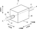
- FIG. 1 is a perspective view of a ventilation system according to one embodiment of the invention
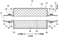
- FIG. 2 is a cross-sectional view of a ventilation system according to one embodiment of the invention, showing section AA of FIG. 1
- FIG. It is a figure which shows the upstream end surface of the housing
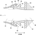
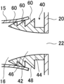
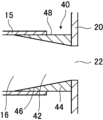
- FIG. 11 is a cross-sectional view of a connection portion according to a conventional example; It is a sectional view of the terminal area concerning the 1st modification.
- FIG. 11 is a cross-sectional view of a connection portion according to a second modified example;
- FIG. 11 is a cross-sectional view of a connecting portion according to a third modified example; It is a figure which shows the modification of the connection method of a 1st connection part and an upstream cylinder.
- FIG. 4 is a diagram showing a model applicable to the present invention among the calculation models of Calculation Example 1;
- FIG. 4 is a diagram showing a model applicable to the present invention among the calculation models of Calculation Example 1
- FIG. 10 is a diagram showing a model corresponding to a conventional example among the calculation models of Calculation Example 1
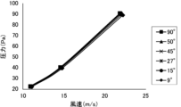
- 8 is a diagram showing the relationship between the pressure on the upstream side of the
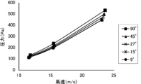
- FIG. 10 is a diagram showing the relationship between the pressure on the upstream side of the second connection portion and the flow velocity on the downstream side of the second connection portion obtained in Calculation Example 2;
- FIG. 10 is a diagram showing the relationship between the pressure on the upstream side of the second connecting portion at a flow velocity of 20 m/s and the inclination angle of the inner peripheral surface of the second connecting portion;
- 1 is a schematic diagram showing the configuration of a ventilation system according to Example 1.
- FIG. FIG. 3 is a schematic diagram showing the configuration of a ventilation system according to a comparative example;
- FIG. 5 is a diagram showing measurement results of a muffled volume by a muffler for each of Example 1 and Comparative Example;
- each member used to implement the present invention can be arbitrarily determined according to the application of the present invention and the technical level at the time of implementation of the present invention.
- the present invention also includes equivalents thereof.
- a numerical range represented using “to” means a range including the numerical values described before and after “to” as lower and upper limits.
- the terms “perpendicular”, “perpendicular” and “parallel” include the range of error that is permissible in the technical field to which the present invention belongs.
- the terms “perpendicular,””perpendicular,” and “parallel” herein mean within ⁇ 10° or less of strictly orthogonal, perpendicular, or parallel, and the like.
- the error from strict orthogonality or parallelism is preferably 5° or less, more preferably 3° or less.
- the meanings of "the same,””identical,””equal,” and “uniform” may include the range of error generally accepted in the technical field to which the present invention belongs.
- the meanings of "all”, “any” and “all” include the range of error generally accepted in the technical field to which the present invention belongs, in addition to the case of 100%. for example, 99% or more, 95% or more, or 90% or more.
- “silencing” in the present invention is a concept that includes both sound insulation and sound absorption.
- Sound insulation means shielding sound, in other words, not allowing sound to pass through.
- Sound absorption means reducing reflected sound, and in simple terms it means absorbing sound (sound).
- the X direction is the extension direction of the intra-housing air passage 26, which will be described later, and corresponds to the first direction of the present invention.
- the Z direction corresponds to the second direction of the invention, and the Y direction corresponds to the third direction of the invention.
- the side closer to the exhaust port in the ventilation path will be referred to as the "downstream side", and the opposite side will be referred to as the "upstream side”.
- FIG. 3 is a diagram showing the upstream end face of the housing 20 provided in the muffler 14, and the exit opening 24 that does not appear on the upstream end face is indicated by broken lines in FIG.
- the ventilation system 10 muffles noise within the system while allowing an air current (wind) to flow along a predetermined route.
- the ventilation system 10 as shown in FIGS.
- the air passage 12 is composed of a cylindrical body such as a hose or duct, except for an expansion portion which will be described later.
- the cylindrical body may be a cylinder or a square cylinder.
- the airflow (wind) sent from the non-air supply source flows toward the exhaust port located at the end of the ventilation path 12 .
- the muffler 14 forms an extension in the air passage 12 .
- the expanded portion is a portion in which the cross-sectional area of the internal space is wider than the portion of the air passage 12 other than the expanded portion (hereinafter also referred to as the normal portion).
- the "cross-sectional area" corresponds to the size of the cross section, and the cross section is the direction in which the ventilation path 12 extends, in other words, the cross section having the first direction as the normal direction.
- the muffler 14 has a housing 20, a sound absorbing member 30, a first connection portion 40, and a second connection portion 50, as shown in FIGS.
- the muffler 14 muffles sound entering the housing 20 by resonance (acoustic resonance) within the housing 20 and sound absorption by the sound absorbing member 30 .
- the housing 20 is a box-shaped or cylindrical hollow body having an outer wall.
- the outer wall of the housing 20 is a relatively thin plate material, and forms both ends of the housing 20 in the XYZ directions.
- the material of the outer wall is not particularly limited, and metal materials, resin materials, reinforced plastic materials, carbon fibers, etc., can be used, for example.
- metal materials include aluminum, titanium, magnesium, tungsten, iron, steel, chromium, chrome molybdenum, nichrome molybdenum, copper, steel galvanized cold commercial (SGCC), and alloys such as stainless steel.
- metal materials such as Examples of resin materials include acrylic resin, polymethyl methacrylate, polycarbonate, polyamideoid, polyarylate, polyetherimide, polyacetal, polyetheretherketone, polyphenylene sulfide, polysulfone, polyethylene terephthalate, polybutylene terephthalate, polyimide, ABS resin (acrylonitrile, flame-retardant ABS resin, butadiene, styrene copolymer synthetic resin), polypropylene, triacetylcellulose (TAC), polypropylene (PP), polyethylene (PE: polyethylene), polystyrene (PS: Polystyrene), ASA (Acrylate Sthrene Acrylonitrile) resin, polyvinyl chloride (P
- Reinforced plastic materials include carbon fiber reinforced plastics (CFRP) and glass fiber reinforced plastics (GFRP). Further, as the material for the outer wall of the housing 20, natural rubber, chloroprene rubber, butyl rubber, EPDM (ethylene-propylene-diene rubber), silicone rubber, and rubbers including these crosslinked structures can be used.
- CFRP carbon fiber reinforced plastics
- GFRP glass fiber reinforced plastics
- each portion of the outer wall of the housing 20 may be made of the same material, or a portion of the housing 20 may be made of a material different from that of the surrounding portion.
- a portion of the housing 20 may be made of the same material as the peripheral portion but have a different thickness (plate thickness) than the peripheral portion.
- an inlet opening 22 is provided at the upstream end of the housing 20 in the X direction, and an outlet opening 24 is provided at the downstream end.
- the inlet opening 22 and the outlet opening 24 are circular holes penetrating the outer wall of the housing 20 in the X direction and communicate with the internal space of the housing 20 .
- the contour shape of each of the entrance opening 22 and the exit opening 24 is not limited to a circle, and may be, for example, a quadrangle or a polygon with five or more sides.
- the airflow in the ventilation path 12 flows into the housing 20 from the upstream side of the housing 20 through the inlet opening 22 and flows out of the housing 20 through the outlet opening 24 .
- an in-housing air passage 26 extending from the inlet opening 22 to the exit opening 24 is formed inside the housing 20 , and the in-housing air passage 26 constitutes a part of the air passage 12 .
- the intra-housing ventilation path 26 extends linearly along the X direction (first direction). Therefore, the airflow (wind) flows in the X direction within the housing 20 , in other words, the X direction corresponds to the ventilation direction within the housing 20 .
- the inlet opening 22 and the outlet opening 24 each extend perpendicularly to the outer wall of the housing 20, are formed through the outer wall, and have a length (depth) corresponding to the thickness of the outer wall. have.
- each of the inlet opening 22 and the outlet opening 24 has a uniform diameter (opening size) over a range from the upstream end of each opening to the other downstream end.
- the existence range of the entrance opening 22 and the existence range of the exit opening 24 in the Y direction and the Z direction overlap.
- the existence range of each opening in the Y direction and Z direction is the range in which each opening exists on the virtual plane (YZ plane) when each opening is projected onto the virtual plane having the X direction as the normal direction. be. Since the existence range of the entrance opening 22 and the existence range of the exit opening 24 overlap in this way, the ventilation in the housing 20 is improved, and the air (wind) flows smoothly from the entrance opening 22 toward the exit opening 24. flow.
- the entrance opening 22 and the exit opening 24 are of the same size, and the existence range of the entrance opening 22 and the existence range of the exit opening 24 are completely the same.
- the size of the opening means the area of the opening.
- the size of each of the inlet opening 22 and the outlet opening 24 may differ from each other.
- the existence range of the smaller openings is contained inside the existence range of the larger openings.
- the existence range of the entrance opening 22 and the existence range of the exit opening 24 may partially overlap.
- the existence range of the entrance opening 22 and the existence range of the exit opening 24 may not overlap in the Y direction and the Z direction, and may be separated from each other (may be shifted).
- the intra-casing ventilation path 26 is not limited to extending linearly, and may be bent at a midpoint.
- each of the entrance opening 22 and the exit opening 24 is provided in the central portion of the housing 20 or in a portion near the end of the housing 20 in the Z direction.
- the inlet opening 22 and the outlet opening 24 may be provided in the central portion of the housing 20 in the direction that intersects the intra-housing air passage 26, or may be provided at positions biased toward the end side of the housing 20.
- the sound absorbing member 30 is arranged inside the housing 20 so as to surround the air passage 26 within the housing. It absorbs sound entering the housing 20, especially high frequency sound.
- a sound absorbing material that absorbs sound by converting sound energy into heat energy can be appropriately used.
- the sound absorbing material is arranged in the housing 20 in the shape of a cylinder or square tube that surrounds the entire circumference of the in-housing air passage 26 .
- sound-absorbing materials include porous sound-absorbing materials such as foams, foam materials, and non-woven fabric-based sound-absorbing materials.
- foams and foam materials include foamed urethane foams such as Calmflex F from INOAC Corporation and urethane foams from Hikari Corporation, soft urethane foams, ceramic particle sintered materials, phenolic foams, melamine foams, and Examples include polyamide foam.
- non-woven fabric sound absorbing materials include microfiber non-woven fabrics such as 3M's Thinsulate, polyester non-woven fabrics such as Tokyo Soundproof's White Qon and Bridgestone KBG's QonPET (thin surface side with high density). nonwoven fabric and nonwoven fabric on the back side with low density), plastic nonwoven fabrics such as acrylic fiber nonwoven fabrics, natural fiber nonwoven fabrics such as wool and felt, metal nonwoven fabrics, glass nonwoven fabrics, etc. is mentioned.
- the sound absorbing material forming the sound absorbing member 30 may be a sound absorbing material made of a material containing minute air, specifically, a sound absorbing material made of glass wool, rock wool, nanofiber, etc., and various other sound absorbing materials. is available.
- nanofiber fibers include silica nanofibers and acrylic nanofibers such as XAI manufactured by Mitsubishi Chemical Corporation.
- the flow resistivity of the sound absorbing material is preferably 1000 (Pa ⁇ s/m 2 ) to 100000 (Pa ⁇ s/m 2 ). If the sound absorbing member 30 has a laminated structure in which multiple layers are stacked, the flow resistance of the entire structure can be measured and the flow resistivity can be calculated from the thickness of the entire structure.
- a sound absorbing body made of a plate or a film in which numerous through holes having a diameter of about 100 ⁇ m are formed can be used as the sound absorbing member 30.
- sound can be absorbed by the sound absorbing body and the back space formed on the back side of the sound absorbing body.
- the microperforated plate include an aluminum microperforated plate such as Suono manufactured by Daiken Kogyo Co., Ltd., and a vinyl chloride resin microperforated plate such as Dynok manufactured by 3M.
- a plurality of sound absorbing members 30 may be used in combination by arranging another sound absorbing material in these back spaces.
- the sound absorbing member 30 can also be considered.
- the sound absorbing member 30 is composed of a plate-like body or a film-like body that resonates when a sound having a frequency close to the resonance frequency is incident, and the internal loss of the plate or film converts sound energy into heat energy. It may be one that converts to and absorbs sound.
- the sound absorbing member 30 has a resonator-type sound absorbing structure made up of a perforated plate. can be converted to Alternatively, a plurality of sound absorbing members 30 may be used in combination, for example, by arranging these sound absorbing structures and separate sound absorbing materials.
- part of the sound absorbing member 30 may enter the in-housing air passage 26 at a midpoint of the in-housing air passage 26 .
- the sound absorbing member 30 is preferably arranged in a state of avoiding the in-housing air passage 26, that is, arranged so as not to enter the in-housing air passage 26.
- the occupation rate of the sound absorbing member 30 is preferably 80% or more, more preferably 90% or more. is more preferred, and 95% is particularly preferred.
- the occupancy rate of the sound absorbing member 30 is the ratio (volume ratio) of the area occupied by the sound absorbing member 30 to the volume of the space inside the housing 20 excluding the air passage 26 in the housing.
- the sound absorbing member 30 fills the internal space of the housing 20 from one end (upstream end) in the X direction to the other end (downstream end).
- a gap may be provided between the inner wall surface of the housing 20 and the sound absorbing member 30, or the sound absorbing member 30 may be filled without any gap.
- the first connecting portion 40 is a cylindrical portion that protrudes from the edge of the inlet opening 22 at one end of the housing 20 in the X direction (specifically, the upstream end surface), and is a ventilation path. It functions as 12 joints.
- an opening portion 42 is provided which is a hole formed in a substantially truncated cone shape or a substantially truncated pyramid shape. The opening 42 is adjacent to the inlet opening 22 and communicates with the intra-housing air passage 26 .
- the first connecting portion 40 connects the upstream side air passage 16 and the inlet opening 22 by being connected to the upstream side cylindrical body 15 .
- the upstream air passage 16 is a portion of the air passage 12 located upstream of the inlet opening 22 .
- the upstream cylinder 15 is a cylinder such as a hose or a duct that forms the upstream air passage 16 .
- the second connecting portion 50 is a cylindrical portion that protrudes from the edge of the outlet opening 24 at the other end of the housing 20 in the X direction (more specifically, the downstream end face). It functions as a joint for the channel 12.
- an opening portion 52 is provided which is a hole formed in a substantially truncated cone shape or a substantially truncated pyramid shape. The opening 52 is adjacent to the outlet opening 24 and communicates with the intra-enclosure air passage 26 .
- the second connecting portion 50 connects the downstream side air passage 18 and the outlet opening 24 by being connected to the downstream side cylindrical body 17 .
- the downstream air passage 18 is the portion of the air passage 12 located downstream of the outlet opening 24 .
- the downstream cylinder 17 is a cylinder such as a hose or a duct that forms the downstream air passage 18 .
- the second connecting portion 50 is connected to the downstream cylinder 17, so that the downstream ventilation path 18, the opening 52, and the intra-casing ventilation path 26 are aligned and continuous.
- the first connecting portion 40 is connected to the upstream cylinder 15 by being inserted into the upstream cylinder 15 (a hose in the configuration shown in FIG. 2) as shown in FIG.
- the second connection portion 50 is connected to the downstream cylinder 17 by being inserted into the downstream cylinder 17 (a hose in the configuration shown in FIG. 2).
- each of the first connecting portion 40 and the second connecting portion 50 is configured by a resin molded product, more specifically, a resin molded product produced by injection molding or the like.
- An example of the resin material forming each connecting portion is the same as the example of the resin material forming the casing 20 described above.
- the housing 20, the first connection portion 40 and the second connection portion 50 are integrally molded. It may be a single part.
- first connection portion 40 and the second connection portion 50 may be separate from the housing 20 .
- the means for attaching the first connection portion 40 and the second connection portion 50 to the housing 20 is not particularly limited.
- the flange may be fixed to the housing 20 with screws or the like.
- the first connecting portion 40 and the second connecting portion 50 may be fixed to the end surface of the housing 20 with an adhesive or the like.
- first connecting portion 40 and the second connecting portion 50 may be made of a material different from that of the housing 20.
- the housing 20 may be made of a resin material, and the first connecting portion 40 and the second connecting portion 50 may be constructed of a metallic material.
- the housing 20 may be made of a metal material, and the first connection portion 40 and the second connection portion 50 may be made of a resin material.
- the openings 42 and 52 in each of the first connection portion 40 and the second connection portion 50 move closer to the in-housing air passage 26 in the X direction. gradually shrinking. More specifically, in the air passage 12, the cross-sectional area of the air passage 12 is gradually reduced at the portions adjacent to the in-housing air passage 26 (that is, the openings 42 and 52) as the in-housing air passage 26 is approached. there is In this embodiment, the cross-sectional areas of the openings 42 and 52 change linearly in proportion to the distance from the in-housing air passage 26 .
- the cross-sectional area of the portion of the air passage 12 provided inside the housing 20, that is, the in-housing air passage 26, is made smaller than the cross-sectional area of the normal portion.
- the cross-sectional area of the ventilation path 12 is gradually changed in order to suppress rapid changes in the cross-sectional area of the ventilation path 12 .
- the cross-sectional area on the side of the inlet opening 22 is gradually decreased toward the downstream side, and the cross-sectional area on the side of the outlet opening 24 is gradually decreased toward the upstream side.
- the thickness of the sound absorbing material 110 becomes thin near the entrance opening 102 and near the exit opening 104 of the muffler 100. is likely to decrease.
- the overall thickness of the sound absorbing material 110 is increased. becomes large. In this case, it is necessary to ensure a wider installation space for the silencer 100, and the installation location of the silencer 100 may be limited.
- the cross-sectional area of the ventilation path 12 at the first connection portion 40 and the second connection portion 50 outside the housing 20 that accommodates the sound absorbing member 30 is the same as the ventilation inside the housing. It becomes smaller as the road 26 is approached.
- the in-housing air passage 26 can be made narrower than the normal portion without reducing the thickness of the sound absorbing member 30 inside the housing 20 .
- the pressure loss in the air passage 12 can be reduced and wind noise can be suppressed without impairing the silencing properties.
- the muffler 14 of the present embodiment has a compact structure, yet exhibits excellent muffling properties and can reduce the pressure loss in the air passage 12 .
- each of the first connection portion 40 and the second connection portion 50 includes an opening 42 as shown in FIGS. , 52 are provided.
- the outer peripheral portions 44 , 54 have inner peripheral surfaces 46 , 56 facing the openings 42 , 52 and outer peripheral surfaces 48 , 58 opposite to the inner peripheral surfaces 46 , 56 .
- the inner peripheral surfaces 46, 56 of each of the first connection portion 40 and the second connection portion 50 are tapered surfaces, as shown in FIGS. 4A and 4B, and are inclined with respect to the X direction (first direction).
- the tapered surface is a surface in which the size of the cross section with the X direction as the normal direction changes concentrically.
- the inclination angle of each portion of the inner peripheral surfaces 46, 56 with respect to the X direction is 0.1 degrees or more and 45 degrees or less.
- the inclination angle of each part of the inner peripheral surfaces 46, 56 is an angle (strictly speaking, an acute angle) at which the generatrix of each part of the inner peripheral surfaces 46, 56 in the circumferential direction of the inner peripheral surfaces 46, 56 is inclined with respect to the X direction. , denoted by the symbol ⁇ in FIGS. 4A and 4B.
- a generatrix at each portion of the inner peripheral surfaces 46 and 56 is a line of intersection between the inner peripheral surfaces 46 and 56 and a cross-sectional plane orthogonal to the inner peripheral surfaces 46 and 56 at each portion.
- the above inclination angle ⁇ may be uniform in the circumferential direction of the inner peripheral surfaces 46, 56, or may vary according to the position in the circumferential direction. Further, the magnitude of the inclination angle ⁇ is preferably 0.1 degrees to 30 degrees, more preferably 0.1 degrees to 20 degrees, and more preferably 0.1 degrees to 10 degrees. Especially preferred.
- the opening areas of the adjacent inlet openings 22 are the same.
- the cross-sectional area of the upstream end that is, the end on the side of the in-casing air passage 26
- the opening area of the outlet opening 24 adjacent to the upstream end are identical.
- the open area of each of the inlet opening 22 and the outlet opening 24 is the size of the respective opening and is the area enclosed by the edges of the opening.
- a step is not formed at the boundary position between the opening 42 and the entrance opening 22 in the first connection part 40 and the boundary position between the opening 52 and the exit opening 24 in the second connection part 50 .
- Each of the first connection portion 40 and the second connection portion 50 is configured by a hose nipple type joint, as shown in FIGS. 4A and 4B.
- unevenness is formed along the X direction on the outer peripheral surfaces 48 and 58 of each connecting portion.
- each convex portion 60 has an X It is provided in a row in multiple directions.
- the outer peripheral surfaces 48, 58 protrude outward at the end closest to the housing 20, and the outer diameter of the convex portion 60 gradually decreases as the distance from the housing 20 increases. . That is, each convex portion 60 has a tapered shape.
- the first connecting portion 40 inserted into the upstream cylindrical body 15 made of a hose or the like is prevented from being detached from the upstream cylindrical body 15, and the upstream cylindrical body 15 and the first connecting portion are prevented from coming off. 40 can be maintained in good condition.
- the second connecting portion 50 inserted into the downstream cylindrical body 17 made of a hose or the like is prevented from coming off from the downstream cylindrical body 17, and the connection between the downstream cylindrical body 17 and the second connecting portion 50 is prevented. can be maintained in good condition.
- the tapered shape of the convex portion 60 described above can enhance the adhesion between the upstream cylinder 15 and the first connection portion 40 and the adhesion between the downstream cylinder 17 and the second connection portion 50 . . As a result, the airtightness of the air passages 12 , particularly the upstream air passages 16 and the downstream air passages 18 is enhanced.
- the outer peripheral portion 44 The thickness of 54 becomes smaller as the distance from the housing 20 increases.
- the thickness corresponds to the distance between the inner peripheral surfaces 46 , 56 and the outer peripheral surfaces 48 , 58 of the outer peripheral portions 44 , 54 .
- outer peripheral portions 44 and 54 have an uneven structure and include a plurality of convex portions 60 arranged in the X direction, as shown in FIG.
- the thickness is defined by using the outer peripheral surfaces 48 and 58 as imaginary planes passing through (indicated by broken lines in FIG. 4C).
- the second connecting portion 50 when the second connecting portion 50 is inserted into the downstream cylindrical body 17 made of a hose or the like, as shown in FIG. It gently bends along the outer peripheral surface 58 of the second connecting portion 50 . As a result, the inner peripheral surface 56 of the second connecting portion 50 and the inner surface of the downstream cylinder 17 are smoothly continuous, and formation of a step between these surfaces can be suppressed. As a result, pressure loss and wind noise due to formation of a step can be suppressed at the connecting portion between the downstream cylinder 17 and the second connecting portion 50 .
- the thickness of the outer peripheral portions 44 and 54 at the distal end portion of each of the first connection portion 40 and the second connection portion 50 decreases as the distance from the housing 20 increases.
- the thickness of the outer peripheral portions 44 and 54 may decrease as the distance from the housing 20 increases over the entire range from the distal end to the proximal end of each connecting portion.
- the inner diameter of the downstream end of the opening 42 in the first connecting portion 40 (the end on the side of the air passage 26 in the housing), that is, the minimum inner diameter of the opening 42 is 150 mm or less.
- the inner diameter of the upstream end of the opening 52 in the second connecting portion 50 (the end on the side of the air passage 26 in the housing), that is, the minimum inner diameter of the opening 52 is 150 mm or less.
- the flow velocity of the air current (wind) inside the air passage is relatively high. Under conditions of high flow velocity, the effect of the ventilation system 10 of the present embodiment becomes significant. That is, the faster the flow velocity, the greater the pressure loss and the more likely wind noise is generated.
- the flow velocity of the in-housing air passage 26 is, for example, 10 m/s or more. Under such circumstances, the effect of suppressing pressure loss and wind noise in the muffler 14 is exhibited satisfactorily.
- each of the openings 42, 52 at the end on the side of the internal air passage 26 is preferably 150 mm or less, more preferably 100 mm or less, and particularly preferably 50 mm or less. Moreover, from the viewpoint of molding accuracy, the inner diameter is preferably 1 mm or more.
- the cross-sectional area (size of the cross section) of the openings 42 and 52 of the first connecting portion 40 and the second connecting portion 50 becomes smaller as it approaches the in-housing air passage 26, but is limited to this. not something.
- the cross-sectional area of one of the openings 42 and 52 may become smaller as it approaches the intra-housing air passage 26 .
- the thickness of the outer peripheral portions 44 and 54 at the distal end portions of the first connection portion 40 and the second connection portion 50 becomes smaller as the distance from the housing 20 increases, but the present invention is not limited to this. .
- the thickness of the outer peripheral portions 44 and 54 at either one of the tip portions may decrease as the distance from the housing 20 increases.
- the cross-sectional areas of the openings 42 and 52 in each of the first connection portion 40 and the second connection portion 50 change linearly in the X direction in proportion to the distance from the in-housing air passage 26. do.
- the cross-sectional areas of the openings 42 and 52 may change non-linearly, for example, exponentially, with respect to the distance from the in-housing air passage 26. . That is, the inner peripheral surfaces 46 and 56 of the first connecting portion 40 and the second connecting portion 50, which are tapered surfaces, may be surfaces curved in the X direction.
- the inner peripheral surfaces 46 and 56 are surfaces in which the size of the cross section with the X direction as the normal direction changes concentrically. , the cross-sectional size may vary eccentrically.
- the outer peripheral surfaces 48 and 58 of each of the first connection portion 40 and the second connection portion 50 are surfaces on which unevenness is formed along the X direction, but the present invention is not limited to this.
- the outer peripheral surfaces 48 and 58 may be smooth surfaces without irregularities.
- the first connection portion 40 is inserted inside the upstream cylinder 15 and connected to the upstream cylinder 15
- the second connection portion 50 is inserted inside the downstream cylinder 17 and connected to the downstream cylinder 17 . It was decided to connect with the side cylindrical body 17 .
- the connection mode of each connecting portion is not particularly limited, and the tip of the first connecting portion 40 and the tip of the upstream cylinder 15 may be connected while they are butted against each other.
- the tip of the second connection portion 50 and the tip of the downstream cylinder 17 may be connected while they are butted against each other.
- the tip of the upstream cylinder 15 is inserted inside the first connecting part 40, and the first connector 40 and the tip of the upstream cylinder 15 are connected while overlapping each other.
- the tip of the downstream tubular body 17 may be inserted into the inside of the second connecting part 50 to connect the second connecting part 50 and the tip of the downstream tubular body 17 while overlapping each other.
- the inner diameter of the upstream side air passage 16 (represented as D1 in FIGS. 8A and 8B) is set to 30 mm
- the inner diameter of the internal air passage 26 (represented as D2 in FIGS. 8A and 8B) is set to 24 mm. bottom.
- the minimum inner diameter of the opening 42 is set to the inner diameter D2 of the air passage 26 in the housing.
- the pressure at the predetermined position of the upstream ventilation path 16 (the position indicated by x1 in FIGS. 8A and 8B) and the predetermined position of the internal ventilation path 26 (in FIGS. 8A and 8B, The relationship with the flow velocity at the position indicated as x2) was obtained. Specifically, the value of the flow velocity at position x2 was set, and the pressure required at position x1 to achieve the set flow velocity was determined. Further, for each inclination angle ⁇ , the set value of the flow velocity at the position x2 was changed, and the pressure at the position x1 was obtained for each set value. Flow velocities were set at about 10 m/s, about 15 m/s and about 23 m/s. Flowsquare 4.0, which is fluid calculation software, was used for the calculation.
- Calculation results in Calculation Example 1 are shown in FIG. Also, from the calculation results shown in FIG. 9, an approximate curve showing the relationship between the pressure at the position x1 and the flow velocity (wind velocity) at the position x2 was obtained for each inclination angle ⁇ . Furthermore, for each inclination angle ⁇ , the pressure at the position x1 when the flow velocity at the position x2 reaches a predetermined value (specifically, 20 m/s) was obtained from the above approximated curve. FIG. 10 shows the relationship between the tilt angle ⁇ thus obtained and the pressure at the position x1.
- the inclination angle ⁇ is 45 degrees or less, the pressure at the position x1 decreases. Therefore, by setting the inclination angle ⁇ to 45 degrees or less, the resistance between the opening 42 of the first connecting portion 40 and the upstream air passage 16 is greatly reduced, and the pressure loss at that position is suppressed. It turned out to be Also, from FIG. 10, it was found that the smaller the inclination angle ⁇ , the greater the degree of decrease in pressure loss. Therefore, it is considered that the inclination angle ⁇ is preferably 30 degrees or less, more preferably 20 degrees or less, and particularly preferably 10 degrees or less.
- the tilt angles ⁇ were set to 45 degrees, 27 degrees, 15 degrees and 9 degrees.
- Case 2B a calculation model was used in which the in-housing air passage 26, the opening 52, and the downstream side air passage 18 are configured by horizontally reversing FIG. 8B. In this model, a vertical step is formed between the opening 52 and the downstream air passage 18. In other words, the inclination angle .theta. is 90 degrees.
- the inner diameter of the downstream air passage 18 was set to 30 mm, and the inner diameter of the in-casing air passage 26 was set to 24 mm. Further, in the case 2A, the minimum value of the inner diameter of the opening 52 is set to the inner diameter of the in-housing air passage 26 . Then, for each case, the relationship between the pressure at the predetermined position x1 of the internal ventilation passage 26 and the flow velocity (wind speed) at the predetermined position x2 of the downstream ventilation passage 18 is obtained in the same manner as in Calculation Example 1. rice field. Calculation results in Calculation Example 2 are shown in FIG.
- FIG. 12 shows the relationship between the inclination angle ⁇ obtained in this way and the pressure at the predetermined position x1 of the internal ventilation passage 26.
- the inclination angle ⁇ is 45 degrees or less, the pressure at the predetermined position x1 of the intra-housing air passage 26 decreases. Therefore, by setting the inclination angle ⁇ to 45 degrees or less, the resistance between the opening 52 of the second connection portion 50 and the downstream air passage 18 is greatly reduced, and the pressure loss at that position is suppressed. It turned out to be Further, from FIG. 12, it can be seen that the smaller the inclination angle ⁇ , the greater the degree of decrease in pressure loss. Therefore, the inclination angle ⁇ is preferably 30 degrees or less, more preferably 20 degrees or less, and 10 degrees or less. is considered particularly preferred.
- Example 1 In Example 1, the ventilation system 10 shown in FIG. 13A was made.
- a polyvinyl chloride (PVC) pipe having an inner diameter of 70 mm and a length in the X direction of 250 mm was used as the housing 20 of the muffler 14 .
- a sound absorbing member 30 made of a cylindrical sound absorbing material having a hole with an inner diameter of 24 mm was arranged inside the housing 20 .
- a first connecting portion 40 is provided at the upstream end of the housing 20, and a second connecting portion 50 is provided at the downstream end.
- the length (projection length) in the X direction of each of the first connection portion 40 and the second connection portion 50 is 50 mm.
- the cross-sectional area of the openings 42 and 52 in each of the first connection portion 40 and the second connection portion 50 decreases as the housing 20 is approached.
- the inner diameter of the end of the openings 42 and 52 closest to the housing 20, ie, the minimum value of the inner diameter, is 24 mm.
- the inclination angle of the inner peripheral surfaces 46 and 56 of each of the first connection portion 40 and the second connection portion 50 was set to 3 degrees. Further, by connecting resin hoses forming the upstream cylinder 15 or the downstream cylinder 17 to each of the first connection part 40 and the second connection part 50, the muffler 14 can be placed in the middle of the air passage 12. placed.
- Example 1 the silencing characteristics of the muffler 14 of the ventilation system 10 configured as described above were measured. Specifically, the resin hose connected to one connection part was connected to a speaker as a sound source, and white noise was emitted from the speaker. In addition, the resin hose connected to the other connection part was placed in the reverberation chamber, and the sound pressure was measured when white noise was flowed in the reverberation chamber. The sound pressure was measured with the muffler 14 and without the muffler 14, and the silencing volume by the muffler 14 was calculated from the difference between the two measurement results.
- Example 1 the resin hose connected to one connection portion was connected to a fan (not shown), and the resin hose connected to the other connection portion was attached with an anemometer. Then, the fan was driven while changing the voltage applied to the fan (in other words, the number of revolutions of the fan), and the wind velocity when using the muffler 14 was measured with an anemometer at the end of the hose.
- a ventilation system 10X shown in FIG. 13B was constructed. In the comparative example, the cross-sectional areas of the openings 42X and 52X in each of the first connection portion 40X and the second connection portion 50X are constant.
- the inner diameter of each of the openings 42X and 52X does not change over the range from one end to the other end of the opening, specifically 24 mm. Otherwise, the configuration of the ventilation system 10X of the comparative example is common to the configuration of the ventilation system 10 of the first embodiment.
- the sound pressure in the reverberation room was measured with and without the muffler 14X by the same procedure as in the first embodiment, and the amount of muffled by the muffler 14X was calculated from the difference between the measurement results. bottom.
- the fan was driven while changing the voltage (rotation speed) applied to the fan in the same procedure as in the first example, and the wind speed was measured when the muffler 14X was used.
- FIG. 14 shows the measurement results of the silencing volume of the silencer for each of Example 1 and Comparative Example.
- the horizontal axis of FIG. 14 indicates the sound frequency (unit: Hz), and the vertical axis indicates the muted volume (unit: dB).
- the same degree of muted volume was obtained. From this, it was found that the influence of the inclination angle of the inner peripheral surface (tapered surface) of each of the first connection portion and the second connection portion on the silencing volume is relatively small.
- Table 1 shows the measurement results of the wind speed when using a silencer for each of Example 1 and Comparative Example.
Landscapes
- Engineering & Computer Science (AREA)
- General Engineering & Computer Science (AREA)
- Mechanical Engineering (AREA)
- Chemical & Material Sciences (AREA)
- Combustion & Propulsion (AREA)
- Physics & Mathematics (AREA)
- Acoustics & Sound (AREA)
- Multimedia (AREA)
- Aviation & Aerospace Engineering (AREA)
- Fluid Mechanics (AREA)
- Duct Arrangements (AREA)
Priority Applications (4)
| Application Number | Priority Date | Filing Date | Title |
|---|---|---|---|
| CN202280068240.8A CN118076828A (zh) | 2021-10-11 | 2022-09-05 | 通气系统 |
| EP22880662.6A EP4417855A4 (en) | 2021-10-11 | 2022-09-05 | VENTILATION SYSTEM |
| JP2023554992A JP7702494B2 (ja) | 2021-10-11 | 2022-09-05 | 通気システム |
| US18/631,524 US20240255177A1 (en) | 2021-10-11 | 2024-04-10 | Ventilation system |
Applications Claiming Priority (2)
| Application Number | Priority Date | Filing Date | Title |
|---|---|---|---|
| JP2021166659 | 2021-10-11 | ||
| JP2021-166659 | 2021-10-11 |
Related Child Applications (1)
| Application Number | Title | Priority Date | Filing Date |
|---|---|---|---|
| US18/631,524 Continuation US20240255177A1 (en) | 2021-10-11 | 2024-04-10 | Ventilation system |
Publications (1)
| Publication Number | Publication Date |
|---|---|
| WO2023062966A1 true WO2023062966A1 (ja) | 2023-04-20 |
Family
ID=85987456
Family Applications (1)
| Application Number | Title | Priority Date | Filing Date |
|---|---|---|---|
| PCT/JP2022/033290 Ceased WO2023062966A1 (ja) | 2021-10-11 | 2022-09-05 | 通気システム |
Country Status (5)
| Country | Link |
|---|---|
| US (1) | US20240255177A1 (https=) |
| EP (1) | EP4417855A4 (https=) |
| JP (1) | JP7702494B2 (https=) |
| CN (1) | CN118076828A (https=) |
| WO (1) | WO2023062966A1 (https=) |
Families Citing this family (1)
| Publication number | Priority date | Publication date | Assignee | Title |
|---|---|---|---|---|
| WO2023062965A1 (ja) * | 2021-10-11 | 2023-04-20 | 富士フイルム株式会社 | 通気システム |
Citations (8)
| Publication number | Priority date | Publication date | Assignee | Title |
|---|---|---|---|---|
| JPS55139216U (https=) * | 1979-03-27 | 1980-10-04 | ||
| JPS63275887A (ja) * | 1987-04-30 | 1988-11-14 | 株式会社ブリヂストン | 消音器 |
| JPH02302552A (ja) * | 1989-05-16 | 1990-12-14 | Ryoko:Kk | 空調用消音器 |
| JPH08233346A (ja) * | 1995-02-24 | 1996-09-13 | Matsushita Seiko Co Ltd | 消音装置 |
| JP2008144874A (ja) * | 2006-12-11 | 2008-06-26 | Aron Kasei Co Ltd | 合成樹脂製の管継手 |
| JP4261379B2 (ja) | 2004-02-05 | 2009-04-30 | 株式会社荏原製作所 | サイレンサ |
| JP2015194335A (ja) * | 2014-03-26 | 2015-11-05 | 株式会社荏原製作所 | 消音チャンバ |
| JP2018205426A (ja) * | 2017-05-31 | 2018-12-27 | 株式会社荏原製作所 | 消音ユニットおよびこの消音ユニットを用いた消音構造体 |
Family Cites Families (12)
| Publication number | Priority date | Publication date | Assignee | Title |
|---|---|---|---|---|
| FI56584C (fi) * | 1976-01-21 | 1980-02-11 | Temet Oy | Ljuddaempare foer luft- eller gasstoemningar |
| DE19533270C2 (de) * | 1995-09-08 | 1999-12-09 | Trinova Gmbh | Schalldämpfungsvorrichtung |
| US6116375A (en) * | 1995-11-16 | 2000-09-12 | Lorch; Frederick A. | Acoustic resonator |
| JP3508592B2 (ja) * | 1998-12-21 | 2004-03-22 | 日産自動車株式会社 | 吸音ダクト構造体 |
| JP4764183B2 (ja) * | 2006-01-17 | 2011-08-31 | タイガースポリマー株式会社 | 冷却用消音ダクト |
| SE532660C2 (sv) * | 2007-05-31 | 2010-03-16 | Swegon Ab | Ljuddämpare för ventilationskanaler |
| CZ308291B6 (cs) * | 2014-04-10 | 2020-04-22 | Hanon Systems | Tlumicí zařízení a způsob jeho výroby |
| WO2019005858A1 (en) * | 2017-06-28 | 2019-01-03 | 3M Innovative Properties Company | MICROPERFORATED CONDUIT |
| SE543236C2 (en) * | 2018-03-02 | 2020-10-27 | Lindab Ab | A silencer for airflow in ventilation |
| JP7039440B2 (ja) * | 2018-11-01 | 2022-03-22 | 富士フイルム株式会社 | 消音換気構造 |
| CN112629002B (zh) * | 2021-01-06 | 2022-02-18 | 滁州市新华建筑安装有限责任公司 | 一种建筑工程暖通气流消声器 |
| WO2023062965A1 (ja) * | 2021-10-11 | 2023-04-20 | 富士フイルム株式会社 | 通気システム |
-
2022
- 2022-09-05 CN CN202280068240.8A patent/CN118076828A/zh active Pending
- 2022-09-05 EP EP22880662.6A patent/EP4417855A4/en active Pending
- 2022-09-05 JP JP2023554992A patent/JP7702494B2/ja active Active
- 2022-09-05 WO PCT/JP2022/033290 patent/WO2023062966A1/ja not_active Ceased
-
2024
- 2024-04-10 US US18/631,524 patent/US20240255177A1/en active Pending
Patent Citations (8)
| Publication number | Priority date | Publication date | Assignee | Title |
|---|---|---|---|---|
| JPS55139216U (https=) * | 1979-03-27 | 1980-10-04 | ||
| JPS63275887A (ja) * | 1987-04-30 | 1988-11-14 | 株式会社ブリヂストン | 消音器 |
| JPH02302552A (ja) * | 1989-05-16 | 1990-12-14 | Ryoko:Kk | 空調用消音器 |
| JPH08233346A (ja) * | 1995-02-24 | 1996-09-13 | Matsushita Seiko Co Ltd | 消音装置 |
| JP4261379B2 (ja) | 2004-02-05 | 2009-04-30 | 株式会社荏原製作所 | サイレンサ |
| JP2008144874A (ja) * | 2006-12-11 | 2008-06-26 | Aron Kasei Co Ltd | 合成樹脂製の管継手 |
| JP2015194335A (ja) * | 2014-03-26 | 2015-11-05 | 株式会社荏原製作所 | 消音チャンバ |
| JP2018205426A (ja) * | 2017-05-31 | 2018-12-27 | 株式会社荏原製作所 | 消音ユニットおよびこの消音ユニットを用いた消音構造体 |
Non-Patent Citations (1)
| Title |
|---|
| See also references of EP4417855A4 |
Also Published As
| Publication number | Publication date |
|---|---|
| CN118076828A (zh) | 2024-05-24 |
| EP4417855A4 (en) | 2025-01-29 |
| US20240255177A1 (en) | 2024-08-01 |
| JP7702494B2 (ja) | 2025-07-03 |
| EP4417855A1 (en) | 2024-08-21 |
| JPWO2023062966A1 (https=) | 2023-04-20 |
Similar Documents
| Publication | Publication Date | Title |
|---|---|---|
| RU2425989C2 (ru) | Звукопоглощающее проточно-канальное устройство | |
| WO2021171710A1 (ja) | 消音装置、及び、送気システム | |
| JP6847246B2 (ja) | 防音構造体 | |
| JPWO2012001735A1 (ja) | 空気調和機 | |
| US20240183569A1 (en) | Air passage type silencer | |
| US20240183576A1 (en) | Silencer for ventilation passage | |
| US20240003275A1 (en) | Acoustic impedance change structure and air passage type silencer | |
| WO2023062966A1 (ja) | 通気システム | |
| JP2008138661A (ja) | 遠心送風機 | |
| WO2023062965A1 (ja) | 通気システム | |
| US20240426514A1 (en) | Ventilation-type silencer | |
| EP4498361A1 (en) | Air duct with silencer | |
| WO2022201692A1 (ja) | 防音構造付き通気路 | |
| EP4425066A1 (en) | Ventilation silencer | |
| CN117859171A (zh) | 通风型消音器 | |
| US20240393001A1 (en) | Wind duct with silencer | |
| WO2024090076A1 (ja) | 消音器付き風路 | |
| US20250207611A1 (en) | Wind duct with silencer | |
| CN118235002A (zh) | 通风型消音器 | |
| CN117859172A (zh) | 通气路用消声器 | |
| WO2025239078A1 (ja) | 消音器付き送風機 | |
| TW202212746A (zh) | 風口結構 |
Legal Events
| Date | Code | Title | Description |
|---|---|---|---|
| 121 | Ep: the epo has been informed by wipo that ep was designated in this application |
Ref document number: 22880662 Country of ref document: EP Kind code of ref document: A1 |
|
| WWE | Wipo information: entry into national phase |
Ref document number: 2023554992 Country of ref document: JP |
|
| WWE | Wipo information: entry into national phase |
Ref document number: 202280068240.8 Country of ref document: CN |
|
| WWE | Wipo information: entry into national phase |
Ref document number: 2022880662 Country of ref document: EP |
|
| NENP | Non-entry into the national phase |
Ref country code: DE |
|
| ENP | Entry into the national phase |
Ref document number: 2022880662 Country of ref document: EP Effective date: 20240513 |