WO2023054529A1 - 気密端子 - Google Patents
気密端子 Download PDFInfo
- Publication number
- WO2023054529A1 WO2023054529A1 PCT/JP2022/036297 JP2022036297W WO2023054529A1 WO 2023054529 A1 WO2023054529 A1 WO 2023054529A1 JP 2022036297 W JP2022036297 W JP 2022036297W WO 2023054529 A1 WO2023054529 A1 WO 2023054529A1
- Authority
- WO
- WIPO (PCT)
- Prior art keywords
- ceramic substrate
- hole
- airtight terminal
- terminal according
- opening
- Prior art date
- Legal status (The legal status is an assumption and is not a legal conclusion. Google has not performed a legal analysis and makes no representation as to the accuracy of the status listed.)
- Ceased
Links
Images




Classifications
-
- H—ELECTRICITY
- H01—ELECTRIC ELEMENTS
- H01R—ELECTRICALLY-CONDUCTIVE CONNECTIONS; STRUCTURAL ASSOCIATIONS OF A PLURALITY OF MUTUALLY-INSULATED ELECTRICAL CONNECTING ELEMENTS; COUPLING DEVICES; CURRENT COLLECTORS
- H01R9/00—Structural associations of a plurality of mutually-insulated electrical connecting elements, e.g. terminal strips or terminal blocks; Terminals or binding posts mounted upon a base or in a case; Bases therefor
- H01R9/16—Fastening of connecting parts to base or case; Insulating connecting parts from base or case
Definitions
- the present disclosure relates to airtight terminals.
- vacuum pumps such as turbomolecular pumps use airtight terminals to supply electrical signals from the outside of the vacuum pump to the inside, which is the vacuum space.
- an airtight terminal generally includes a cylindrical metal sleeve, a disk-shaped insulating substrate brazed to the inner peripheral surface of the metal sleeve and having a through hole in the axial direction, and a and a lead pin (conducting member) with a washer (annular member).
- a metal layer (metallized layer) is formed on the inner peripheral surface of the through-hole to a depth of 200 ⁇ m to 5 mm from the peripheral edge of the through-hole of the insulating substrate and the opening of the through-hole.
- a hermetic terminal is described.
- a washer and a lead pin are fixed to this metal layer by brazing.
- the airtight terminal according to the present disclosure includes a cylindrical metal sleeve, a ceramic substrate fixed to the inner peripheral surface of the metal sleeve and having a through hole along the axial direction of the metal sleeve, and a ceramic substrate inserted into the through hole. and a columnar conductive member joined by a brazing material.
- the through-hole has a first opening and a second opening opening in an inverted frustum shape from both ends in the axial direction.
- a metallized layer is coated over the entire inner peripheral surface of the through-hole of the ceramic substrate.
- a vacuum pump according to the present disclosure includes this airtight terminal.
- FIG. 1 is a plan view of an airtight terminal according to an embodiment of the present disclosure
- FIG. FIG. 2 is an explanatory diagram for explaining a cross section taken along line XX shown in FIG. 1
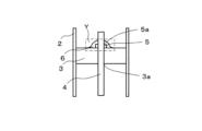
- FIG. 3 is an enlarged explanatory view for explaining a region Y shown in FIG. 2
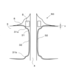
- 3 is an enlarged explanatory view for explaining another embodiment of the region Y shown in FIG. 2
- FIG. 3 is an enlarged explanatory view for explaining another embodiment of the region Y shown in FIG. 2
- FIG. 3 is an enlarged explanatory view for explaining another embodiment of the region Y shown in FIG. 2
- FIG. 3 is an enlarged explanatory view for explaining another embodiment of the region Y shown in FIG. 2
- FIG. 3 is an enlarged explanatory view for explaining another embodiment of the region Y shown in FIG. 2;
- the end of the metal layer formed on the inner peripheral surface of the through-hole of the insulating substrate is positioned inside the through-hole. Become. If the end of the metal layer is located in the through-hole, cracks may occur from the tip of the metal portion toward the insulating base made of ceramic when force majeure is applied.
- An object of the present disclosure is to provide an airtight terminal that can reduce the occurrence of cracks extending from the tip of the metallized layer toward the ceramic substrate even if force majeure is applied from the outside, and that can maintain airtightness for a long period of time. is.
- the metallized layer is coated over the entire inner peripheral surface facing the conductive member in the through hole of the ceramic substrate.
- the edge of the metallization layer is not positioned within the through-hole. Therefore, according to the airtight terminal according to the present disclosure, even if force majeure is applied from the outside, it is possible to reduce the occurrence of cracks extending from the tip of the metallized layer toward the ceramic substrate, and it is possible to maintain airtightness for a long period of time. .
- FIG. 1 is a plan view showing an airtight terminal 1 according to one embodiment.
- the metal sleeve 2 has a cylindrical shape, and as long as it is cylindrical, the shape is not limited, such as a cylindrical shape, a rectangular cylindrical shape (for example, a triangular cylindrical shape, a square cylindrical shape, a pentagonal cylindrical shape, a hexagonal cylindrical shape, etc.).
- the size of the metal sleeve 2 may be appropriately set according to the device provided with the airtight terminal 1 or the like.
- the length of the metal sleeve 2 is, for example, 15 mm or more and 30 mm or less, and the outer diameter is 20 mm or more and 30 mm or less.
- the outer diameter in the case of a rectangular tube means the length of the longest outer edge.
- the metal sleeve 2 is made of, for example, carbon steel, low alloy steel, tool steel, stainless steel, iron, copper, copper alloy, titanium, titanium alloy, molybdenum, molybdenum alloy, Fe—Ni alloy, Fe—Ni—Cr—Ti— Al alloy, Fe--Cr--Al alloy, Fe--Co--Cr alloy Fe--Co alloy, Fe--Co--C alloy, Fe--Ni alloy or Fe--Ni--Co alloy there is
- Carbon steel is an alloy of Fe and 0.02 to 2.14% by mass of C, and contains Si, Mn, P and S in addition to C.
- Examples of such carbon steel include S10C, S12C, S15C, S17C, S20C, S22C, S25C, S28C, S30C, S33C, S35C, S38C, S40C, S43C, S45C, and S48C defined in JIS G 4051:2016. , S50C, S53C, S55C, S58C, S60C, S65C, S70C, and S75C.
- Low alloy steel contains at least one of Al, B, Co, Cr, Cu, La, Mo, Nb, Ni, Pb, Se, Te, Ti, V, W and Zr, and the content of these elements Carbon steel with a total of 5% by mass or less.
- Tool steel refers to carbon tool steel specified in JIS G 4401:2009 and alloy tool steel specified in JIS G 4404:2006.
- Stainless steel is an alloy of Fe and 10.5% by mass or more of Cr, with a C content of 1.2% or less. be done.
- Stainless steel is, for example, SUS304, SUS304L, SUS304ULC, SUS310ULC or SUSXM15J1.
- the ceramic substrate 3 is a member for fixing the conduction member 4 to be described later inside the metal sleeve 2 .
- the ceramic substrate 3 is fixed by the outer peripheral surface of the ceramic substrate 3 and the inner wall surface of the metal sleeve 2, as shown in FIGS. That is, the ceramic substrate 3 is formed according to the inner diameter of the metal sleeve 2 .
- the thickness of the ceramic substrate 3 may be any thickness that allows the conductive member 4 to be fixed, and is, for example, 4 mm or more and 10 mm or less.
- FIG. 2 is an explanatory diagram for explaining a cross section taken along line XX shown in FIG.
- the ceramic substrate 3 is not limited as long as it is made of ceramics.
- ceramics include ceramics containing aluminum oxide, aluminum nitride, silicon carbide, or silicon nitride as a main component.
- the term "main component” refers to a component that accounts for 80% by mass or more of the total 100% by mass of the components that make up the ceramics.
- Each component contained in the ceramics is identified by an X-ray diffractometer using CuK ⁇ rays, and the content of each component may be determined by, for example, an ICP (Inductively Coupled Plasma) emission spectrometer or a fluorescent X-ray spectrometer.
- ICP Inductively Coupled Plasma
- the ceramic substrate 3 has through holes 31 along the axial direction of the metal sleeve 2 .
- the through-hole 31 is a through-hole for inserting the conducting member 4 , and the diameter of the through-hole 31 is appropriately set according to the outer diameter of the conducting member 4 .
- At least one through-hole 31 may be formed in the ceramic substrate 3, and is appropriately set according to the number of the conductive members 4 to be inserted.
- the annular member 5 is positioned on the surface of the ceramic substrate 3.
- the annular member 5 corresponds to a washer, and is made of, for example, carbon steel, low alloy steel, tool steel, stainless steel, iron, copper, copper alloy, titanium, titanium alloy, molybdenum, molybdenum alloy, Fe—Ni alloy, Fe—Ni. -Cr-Ti-Al alloy, Fe-Cr-Al alloy, Fe-Co-Cr alloy Fe-Co alloy, Fe-Co-C alloy, Fe-Ni alloy or Fe-Ni-Co alloy made of metal. Definitions of carbon steel, low alloy steel, tool steel and stainless steel are given above.
- the annular member 5 is not limited as long as it is smaller than the width and thickness of the ceramic substrate 3 and has a size that allows the conductive member 4 to be inserted.
- the outer diameter of the annular member 5 is approximately 1.2 times or more and 2 times or less the outer diameter of the conducting member 4, and particularly 1.4 times or more and 1.8 times or less. Good to have.
- the thickness is about 0.1 mm or more and 0.5 mm or less.
- the annular member 5 is a member that is used as needed, and has a second through hole positioned coaxially with the through hole 31 formed in the ceramic substrate 3 .
- the second through-hole is a through-hole for inserting the conducting member 4 , and the diameter of the second through-hole is appropriately set according to the outer diameter of the conducting member 4 .
- the annular member 5 may be located on one surface of the ceramic substrate 3 as shown in FIG. 2, or may be located on both surfaces.
- the conducting member 4 corresponds to a lead pin, and the shape is not limited as long as it has a columnar shape such as a columnar shape, a prismatic shape (for example, a triangular prismatic shape, a square prismatic shape, a pentagonal prismatic shape, a hexagonal prismatic shape, etc.).
- the length and outer diameter of the conducting member 4 are appropriately set according to the size of the metal sleeve 2, for example.
- the conductive member 4 is made of metal such as copper, oxygen-free copper (for example, alloy number C1020 defined in JIS H 3100:2012 or alloy number C1011 defined in JIS H 3510:2012). .
- At least one conductive member 4 may be included, and the number of conductive members 4 may be appropriately set according to the use of the airtight terminal 1 or the like.
- the conducting member 4 is inserted into the through hole 31 formed in the ceramic substrate 3 and the second through hole formed in the annular member 5 and fixed to the ceramic substrate 3 .
- the surface of the ceramic substrate 3 is brazed using a brazing material 6 so as to cover the annular member 5 .
- the brazing material 6 include BAg-8, BAg-8A, BAg-8B, and BAg-9.
- FIG. 3 is an enlarged explanatory diagram for explaining the region Y shown in FIG. Since the metallized layer 32 is coated over the entire inner peripheral surface of the through hole 31 formed in the ceramic substrate 3 in this way, even if force majeure is applied from the outside, the tip of the metallized layer 32 does not reach the ceramic substrate 3 . The occurrence of cracks directed toward is suppressed. As a result, airtightness can be maintained for a long period of time.
- the metal forming the metallized layer 32 is not limited, and examples thereof include Mo--Mn alloy and Ag--Cu--Ti alloy.
- the metallized layer 32 may have a thickness of, for example, 15 ⁇ m or more and 45 ⁇ m or less.
- the metallized layer 3 is made of a Mo--Mn alloy, the metallized layer 32 may be coated with a Ni plating layer in order to suppress the oxidation of Mo.
- the thickness of the Ni plating layer is, for example, 3 ⁇ m or more and 10 ⁇ m or less.
- the metallized layer 32 may be thicker at the central portion in the axial direction than at both axial end portions of the through hole 31 .
- the central portion of the through-hole 31 may be thicker than the both end portions.
- Both ends in the axial direction mean the vicinity of the first opening 31a and the vicinity of the second opening 31b. Stress is likely to occur in the ceramic substrate 3 in the vicinity of both ends. In order to reduce the stress applied to the ceramic substrate 3, it is preferable to thin the metallized layer 32 at both ends.
- the brazing material 6 expands and contracts in the vertical direction due to repeated heating and cooling, the central portion in the axial direction is less affected by the expansion and contraction. As a result, even if heating and cooling are repeated and cracks are generated in the metallized layer 32 or the ceramic substrate 3, the progress of the cracks can be suppressed.
- the metallized layer 32 may extend to the peripheral edge of at least one of the first opening 31a and the second opening 31b of the ceramic substrate 3, as shown in FIG. Even if force majeure is applied from the outside, the occurrence of cracks extending from the tip of the metallized layer 32 to the ceramic substrate 3 is suppressed. As a result, airtightness can be maintained for a long period of time.
- the through-hole 31 has a first opening 31a and a second opening 31b opening in an inverted frustum shape from both ends in the axial direction.
- first opening 31a and the second opening 31b have a shape that opens in an inverted truncated pyramid shape, compared to a shape other than an inverted truncated pyramid shape (for example, an inverted cone shape or an inverted pyramid shape).
- the stress of the ceramic substrate 3 near the first opening 31a and the second opening 31b is dispersed. As a result, even if heating and cooling are repeated, the ceramic substrate 3 is less likely to crack and can be used for a long period of time.
- the inverted truncated cone shape may be an inverted truncated cone shape, an inverted truncated pyramid shape, or the like depending on the shape of the conductive member 4 (the shape of the first through hole 3a). As shown in FIG. 1, when the conductive member 4 is cylindrical, the inverted truncated cone shape becomes an inverted truncated cone shape.
- the first opening 31 a and the second opening 31 b are symmetrical with respect to a virtual plane perpendicular to the axial direction of the through hole 31 and passing through the center of the thickness of the ceramic substrate 3 .
- uneven distribution of stress in the thickness direction (axial direction) of the ceramic substrate 3 is suppressed.
- cracks or the like are less likely to occur in the ceramic substrate 3, and the ceramic substrate 3 can be used for a long period of time.
- the brazing material 6 positioned between the through hole 31 formed in the ceramic substrate 3 and the conductive member 4 may have a long gap in the thickness direction of the ceramic substrate 3 . Due to the presence of such voids, residual stress is relaxed even if heating and cooling are repeated. At least one tip side of the gap may have a convex curved surface. When at least one tip side of the gap has a convex curved surface, stress concentration is suppressed at the tip of the convex curved surface side. As a result, the occurrence of cracks from the tip on the convex curved surface side is suppressed.
- the annular member 5 may be covered with brazing material 6 from the top surface to the side surface.
- the conductive member 4 is less likely to come off even if a high pressure is applied to the annular member 5 from the outside.
- the brazing filler metal 6 may form a fillet from above the upper surface of the annular member 5 toward the outside of the outer peripheral surface of the annular member 5 .
- the contact area of the brazing material 6 with respect to the ceramic substrate 3 , the conductive member 4 and the annular member 5 can be increased.
- the ceramic substrate 3 is provided with the extending metallized layer 32 and a plated layer (not shown) covering the metallized layer 32, the contact area of the brazing material 6 with respect to the plated layer instead of the ceramic substrate 3 can be expanded. As a result, even if a pulling force is applied to the outside, it becomes difficult to peel off, and it can be used for a long period of time.
- the cross-sectional profile of the brazing material 6 may have concave surfaces 7a, 7b. Since the concave surfaces 7a and 7b are provided, the volume of the brazing material 6 can be reduced compared to the case where the concave surfaces 7a and 7b are not provided. Therefore, the stress applied to the ceramic substrate 3 is reduced, and the occurrence of cracks in the ceramic substrate 3 can be particularly suppressed. In particular, since it has the concave surface 7a, the stress applied to the ceramic substrate 3 is reduced.
- a convex surface 8 is formed at the boundary between the concave surfaces 7a and 7b.
- the top of the convex surface 8 may be close to the line of intersection between the upper surface of the annular member 5 and the outer peripheral surface.
- the thickness of the brazing filler metal near the convex surface 8 is thin. Therefore, the stress applied to the ceramic substrate 3 is reduced, and the occurrence of cracks in the ceramic substrate 3 can be particularly suppressed.
- the average curvature radius of the convex surface 8 may be 60 ⁇ m or more and 190 ⁇ m or less.
- the bonding strength of the conductive member 4 to the ceramic substrate 3 is improved, and when a plurality of conductive members 4 are arranged along the axial direction of the metal sleeve 2, , it is possible to suppress the short circuit between the adjacent conducting members 4 due to the brazing material 6 .
- the conduction member 4 is columnar, the convex surface 8 will have a ring shape surrounding the conduction member 4 .
- the average curvature radius of the convex surface 8 can be measured using a shape analysis laser microscope (manufactured by Keyence Corporation, an ultra-depth color 3D shape measuring microscope (VK-X1100 or its successor model)).
- profile measurement may be performed by setting the illumination method to coaxial illumination, the magnification to 120, and the measurement range including the convex surface 8 to, for example, 2792 ⁇ m ⁇ 2093 ⁇ m per point.
- one measurement range four lines to be measured are drawn from the conductive member 4 side toward the ceramic substrate 3 side so as to include the convex surface 8 .
- the length of one line is, for example, 200 ⁇ m or more and 300 ⁇ m or less.
- At least 3 measurement ranges should be set, and at least 12 lines should be measured.
- Let the average value of the measured values obtained from the 12 lines to be measured be the average radius of curvature of the convex surface 8 .
- FIG. 5 An airtight terminal 50 according to another embodiment of the present disclosure will be described based on FIG. A configuration different from the one embodiment will be described.
- a portion of the annular member 5 may be positioned inside the first opening 31 a of the ceramic substrate 3 . That is, the lower surface of the annular member 5 may be located at a distance D in the axial direction of the first through hole 31 from the surface of the ceramic substrate 3 to the first opening 31a side.
- the volume of the brazing material 6 in the first through hole 31 is reduced by the annular member 5 . Therefore, the stress applied to the ceramic substrate 3 adjacent to the first through hole 31 is reduced, and the occurrence of cracks in the ceramic substrate 3 can be particularly suppressed.
- FIG. 6 An airtight terminal 60 according to another embodiment of the present disclosure will be described based on FIG. A configuration different from the one embodiment will be described.
- the distance between the outer peripheral surface of the conducting member 4 and the inner peripheral surface of the annular member 5 may not be uniform.
- the distance between the outer peripheral surface of the conductive member 4 and the inner peripheral surface of the annular member 5 is W1 on the left side of the paper surface and W2 on the right side of the paper surface, where W1>W2. It is preferable to have such a structure.
- W1 is larger than W2
- the volume of the brazing material 6 between the first region 51 and the conductive member 4 increases in the area on the left side of the drawing.
- W1 is larger than W2
- the distance between the convex surface 8 and the line of intersection between the upper surface of the annular member 5 and the outer peripheral surface can be reduced in the area on the left side of the drawing.
- the volume of the brazing material 6 between the first area 51 and the conducting member 4 increases. In the area on the right side of the page, the volume of the brazing material 6 between the first area 51 and the conducting member 4 decreases.
- the surface roughness curve of the plated layer is 25 % load length ratio and the cut level at 75% load length ratio in the roughness curve. greater than the average value of the cut level difference R ⁇ c2 representing the difference between the cut level at 25% load length factor on the roughness curve of the part and the cut level at 75% load length factor on the roughness curve good too.
- the anchoring effect of the brazed portion is enhanced, so the bonding strength of the brazed portion to the plating layer can be increased.
- the average value of the cutting level difference R ⁇ c2 is smaller than the average value of the cutting level difference R ⁇ c1
- the adhesion of the extended metallized layer 32 to 3 is improved. Furthermore, variations in the thickness of the extended metallized layer 32 are also suppressed.
- the cutting level differences R ⁇ c1 and R ⁇ c2 can be measured using a shape analysis laser microscope (manufactured by Keyence Corporation, an ultra-depth color 3D shape measuring microscope (VK-X1100 or its successor)).
- the illumination system is coaxial illumination, the magnification is 60 times, the cutoff value ⁇ s is absent, the cutoff value ⁇ c is 0.8 mm, the cutoff value ⁇ f is absent, and the end effect is corrected.
- the measurement targets the surface of the plated layer around the conductive member 4 and the exposed portion of the surface of the ceramic substrate 3, and the measurement range per location is, for example, 5657 ⁇ m ⁇ 4232 m.
- a circumference C1 to be measured centered on the axis of the conductive member 4 is drawn on the surface of the plated layer.
- the length per circumference is, for example, 6.2 mm or more and 6.6 mm or less.
- a circumference C2 is drawn on the exposed portion of the surface of the ceramic substrate 3 coaxially with the circumference C1.
- the length per circumference is, for example, 7.8 mm or more and 8.3 mm or less.
- the measured values of the cutting level differences R ⁇ c1 and R ⁇ c2 may be obtained so as to be the same as the number of the conductive members 4, and the respective average values may be calculated. When there is only one conductive member 4, the measured value of the cutting level difference R.delta.c1 and the measured value of the cutting level difference R.delta.c2 can be compared.
- the average value of the cutting level difference R ⁇ c1 is 4 ⁇ m or more and 7 ⁇ m or less, and the average value of the cutting level difference R ⁇ c2 is 1 ⁇ m or more and 2 ⁇ m or less.
- the difference between the average value of the cutting level differences R ⁇ c1 and the average value of the cutting level differences R ⁇ c2 is preferably 2 ⁇ m or more and 5 ⁇ m or less.
- the airtight terminal 1 is manufactured, for example, by the following procedure.
- the metal sleeve 2 is prepared.
- a ceramic substrate 3 is fixed to the inner peripheral surface of this metal sleeve 2 .
- the inner peripheral surface of the through hole 31 formed in the ceramic substrate 3 is metallized over the entire surface in advance to form a metallized layer 32 .
- Metallization is performed by, for example, the molybdenum-manganese method (Mo--Mn method).
- Mo--Mn method molybdenum-manganese method
- the annular member 5 is placed on the ceramic substrate 3 so that the through hole 31 formed in the ceramic substrate 3 and the second through hole formed in the annular member 5 overlap.
- the conducting member 4 is inserted into the through hole 31 and the second through hole, and the ceramic substrate 3 and the conducting member 4 and the annular member 5 are fixed with the brazing material 6 so as to cover the annular member 5 from the upper surface to the side surface. do.
- the mass of the brazing material 6 and the brazing temperature By adjusting the mass of the brazing material 6 and the brazing temperature, the shape of the fillet can be controlled.
- the airtight terminal 1 according to one embodiment is obtained.
- the ceramic substrate 3 may be fixed to the inner peripheral surface of the metal sleeve 2 after the conducting member 4 and the annular member 5 are previously fixed to the ceramic substrate 3 with the brazing material 6 .
- a method of manufacturing an airtight terminal 40 according to another embodiment having recesses 7a, 7b and projections 8 shown in FIG. 4 will be described.
- the metal sleeve 2 is prepared.
- a ceramic substrate 3 is fixed to the inner peripheral surface of this metal sleeve 2 .
- the annular member 5 is coated with the brazing material 6 in advance.
- a paste made of fine powder of the brazing material 6 and an organic solvent is applied to the entire periphery of the annular member 5, that is, the upper surface, the lower surface, the inner peripheral surface, and the outer peripheral surface. It can be produced by heating and cooling.
- the annular member 5 is attached to the ceramic substrate 3 so that the first through hole 31 formed in the ceramic substrate 3 and the second through hole (previously coated with the brazing material 6) formed in the annular member 5 overlap each other. to be placed.
- the conductive member 4 is inserted into the first through hole 3 a and the second through hole, and the ceramic substrate 3 and the conductive member 4 and the annular member 5 are fixed with the brazing material 6 so as to cover the annular member 5 .
- an airtight terminal 40 according to another embodiment is obtained.
- a method of manufacturing an airtight terminal 50 according to another embodiment in which a part of the annular member 5 is positioned inside the first opening 3a' of the ceramic substrate 3 shown in FIG. 5 will be described.
- the lower surface of the annular member 5 is placed on the ceramic substrate when the annular member 5 is placed.
- the annular member 5 is fixed.
- the airtight terminal 60 with different distances W1 and W2 as shown in FIG. 6 can be manufactured as follows. As a first manufacturing method, the annular member 5 is placed on the ceramic substrate 3, and when the conducting member 4 is inserted, the interval between the conducting member 4 and the annular member 5 is made uneven. After that, the annular member 4 and the conducting member 5 are fixed with the brazing material 6 .
- the metal sleeve 2 is prepared.
- a ceramic substrate 3 is fixed to the inner peripheral surface of this metal sleeve 2 .
- the annular member 5 is placed on the ceramic substrate 3 so that the first through hole 31 formed in the ceramic substrate 3 and the second through hole formed in the annular member 5 overlap.
- the conductive member 4 is inserted into the first through hole 3a and the second through hole so that the interval between the conductive member 4 and the annular member 5 is uneven. After that, the annular member 4 and the conducting member 5 are fixed with the brazing material 6 .
- the axial direction is inclined by 10 to 30° with respect to gravity. After that, the brazing material 6 is melted by heating while maintaining the tilted state, and further cooled to solidify the brazing material 6 .
- the metal sleeve 2 is prepared.
- a ceramic substrate 3 is fixed to the inner peripheral surface of this metal sleeve 2 .
- the annular member 5 is placed on the ceramic substrate 3 so that the first through hole 3a formed in the ceramic substrate 3 and the second through hole formed in the annular member 5 overlap each other.
- the conducting member 4 is inserted into the first through hole 3a and the second through hole.
- the ceramic substrate 3 is tilted so that the axial direction of the annular member 5 is tilted by 10 to 30° with respect to the vertical direction.
- the brazing material 6 is heated and then cooled to fix the conducting member 4 and the annular member 5 .
- an airtight terminal 60 according to another embodiment is obtained.
- the upper surface of the ceramic substrate 3 may be ground or polished in advance.
- the airtight terminal 1 is used in various devices.
- Such devices include, for example, vacuum pumps and plasma processing devices such as plasma deposition devices, plasma etching devices, and plasma ashing devices.
- Reference Signs List 1 40, 50, 60 airtight terminal 2 metal sleeve 3 ceramic substrate 31 through hole 31a first opening 31b second opening 32 metallized layer 4 conductive member 5 annular member 6 brazing material
Landscapes
- Ceramic Products (AREA)
- Connections Arranged To Contact A Plurality Of Conductors (AREA)
Priority Applications (1)
| Application Number | Priority Date | Filing Date | Title |
|---|---|---|---|
| JP2023551810A JP7680556B2 (ja) | 2021-09-29 | 2022-09-28 | 気密端子 |
Applications Claiming Priority (2)
| Application Number | Priority Date | Filing Date | Title |
|---|---|---|---|
| JP2021159884 | 2021-09-29 | ||
| JP2021-159884 | 2021-09-29 |
Publications (1)
| Publication Number | Publication Date |
|---|---|
| WO2023054529A1 true WO2023054529A1 (ja) | 2023-04-06 |
Family
ID=85780745
Family Applications (1)
| Application Number | Title | Priority Date | Filing Date |
|---|---|---|---|
| PCT/JP2022/036297 Ceased WO2023054529A1 (ja) | 2021-09-29 | 2022-09-28 | 気密端子 |
Country Status (2)
| Country | Link |
|---|---|
| JP (1) | JP7680556B2 (https=) |
| WO (1) | WO2023054529A1 (https=) |
Citations (4)
| Publication number | Priority date | Publication date | Assignee | Title |
|---|---|---|---|---|
| JPH1116620A (ja) * | 1997-06-23 | 1999-01-22 | Kyocera Corp | 気密端子 |
| WO2013047740A1 (ja) * | 2011-09-30 | 2013-04-04 | 京セラ株式会社 | 金属とセラミックスとの接合体 |
| JP2013193935A (ja) * | 2012-03-21 | 2013-09-30 | Ngk Insulators Ltd | セラミックス部材と金属部材との接合体及びその製法 |
| JP2019149304A (ja) * | 2018-02-27 | 2019-09-05 | 京セラ株式会社 | 密封端子 |
-
2022
- 2022-09-28 JP JP2023551810A patent/JP7680556B2/ja active Active
- 2022-09-28 WO PCT/JP2022/036297 patent/WO2023054529A1/ja not_active Ceased
Patent Citations (4)
| Publication number | Priority date | Publication date | Assignee | Title |
|---|---|---|---|---|
| JPH1116620A (ja) * | 1997-06-23 | 1999-01-22 | Kyocera Corp | 気密端子 |
| WO2013047740A1 (ja) * | 2011-09-30 | 2013-04-04 | 京セラ株式会社 | 金属とセラミックスとの接合体 |
| JP2013193935A (ja) * | 2012-03-21 | 2013-09-30 | Ngk Insulators Ltd | セラミックス部材と金属部材との接合体及びその製法 |
| JP2019149304A (ja) * | 2018-02-27 | 2019-09-05 | 京セラ株式会社 | 密封端子 |
Also Published As
| Publication number | Publication date |
|---|---|
| JP7680556B2 (ja) | 2025-05-20 |
| JPWO2023054529A1 (https=) | 2023-04-06 |
Similar Documents
| Publication | Publication Date | Title |
|---|---|---|
| CN110277342B (zh) | 静电吸盘 | |
| TWI751444B (zh) | 靜電吸盤 | |
| US6106960A (en) | Joined articles, corrosion-resistant joining materials and process for producing joined articles | |
| US6768079B2 (en) | Susceptor with built-in plasma generation electrode and manufacturing method therefor | |
| TW201939664A (zh) | 靜電吸盤 | |
| JPWO2019065710A1 (ja) | 静電チャック装置 | |
| JP7402411B2 (ja) | 静電チャック | |
| US12170219B2 (en) | Electrostatic chuck | |
| KR20140103915A (ko) | 내고온성 복합체의 제조 방법 | |
| JP7583954B2 (ja) | 気密端子 | |
| JPH08316299A (ja) | 静電チャック | |
| WO2023054529A1 (ja) | 気密端子 | |
| CN111128837B (zh) | 静电吸盘 | |
| CN110277343B (zh) | 静电吸盘 | |
| KR102468589B1 (ko) | 합금 용사막 및 막 형성 장치 | |
| US20250183083A1 (en) | Electrostatic chuck member and electrostatic chuck device | |
| US20250158543A1 (en) | Electrostatic chuck member, electrostatic chuck device, and method for manufacturing electrostatic chuck member | |
| JP3037669B1 (ja) | セラミック部材と金属部材の接合体及びこれを用いたウエハ支持部材 | |
| US20250329565A1 (en) | Electrostatic chuck member, electrostatic chuck device, and method for manufacturing electrostatic chuck member | |
| WO2024004778A1 (ja) | 半導体製造装置用部材及び静電チャック装置 | |
| JP2016084256A (ja) | 窒化アルミニウム焼結体及び半導体製造用部品並びに窒化アルミニウム焼結体の製造方法 | |
| JP3752424B2 (ja) | 絶縁継手 | |
| JP4210087B2 (ja) | 電流導入端子 | |
| JP7441370B1 (ja) | セラミックサセプター | |
| JP4578033B2 (ja) | 絶縁継手 |
Legal Events
| Date | Code | Title | Description |
|---|---|---|---|
| 121 | Ep: the epo has been informed by wipo that ep was designated in this application |
Ref document number: 22876395 Country of ref document: EP Kind code of ref document: A1 |
|
| WWE | Wipo information: entry into national phase |
Ref document number: 2023551810 Country of ref document: JP |
|
| NENP | Non-entry into the national phase |
Ref country code: DE |
|
| 122 | Ep: pct application non-entry in european phase |
Ref document number: 22876395 Country of ref document: EP Kind code of ref document: A1 |