WO2023054270A1 - 熱交換器 - Google Patents
熱交換器 Download PDFInfo
- Publication number
- WO2023054270A1 WO2023054270A1 PCT/JP2022/035752 JP2022035752W WO2023054270A1 WO 2023054270 A1 WO2023054270 A1 WO 2023054270A1 JP 2022035752 W JP2022035752 W JP 2022035752W WO 2023054270 A1 WO2023054270 A1 WO 2023054270A1
- Authority
- WO
- WIPO (PCT)
- Prior art keywords
- heat transfer
- transfer fins
- heat exchanger
- outdoor
- flat tubes
- Prior art date
- Legal status (The legal status is an assumption and is not a legal conclusion. Google has not performed a legal analysis and makes no representation as to the accuracy of the status listed.)
- Ceased
Links
Images



Classifications
-
- F—MECHANICAL ENGINEERING; LIGHTING; HEATING; WEAPONS; BLASTING
- F28—HEAT EXCHANGE IN GENERAL
- F28D—HEAT-EXCHANGE APPARATUS, NOT PROVIDED FOR IN ANOTHER SUBCLASS, IN WHICH THE HEAT-EXCHANGE MEDIA DO NOT COME INTO DIRECT CONTACT
- F28D1/00—Heat-exchange apparatus having stationary conduit assemblies for one heat-exchange medium only, the media being in contact with different sides of the conduit wall, in which the other heat-exchange medium is a large body of fluid, e.g. domestic or motor car radiators
- F28D1/02—Heat-exchange apparatus having stationary conduit assemblies for one heat-exchange medium only, the media being in contact with different sides of the conduit wall, in which the other heat-exchange medium is a large body of fluid, e.g. domestic or motor car radiators with heat-exchange conduits immersed in the body of fluid
- F28D1/04—Heat-exchange apparatus having stationary conduit assemblies for one heat-exchange medium only, the media being in contact with different sides of the conduit wall, in which the other heat-exchange medium is a large body of fluid, e.g. domestic or motor car radiators with heat-exchange conduits immersed in the body of fluid with tubular conduits
- F28D1/047—Heat-exchange apparatus having stationary conduit assemblies for one heat-exchange medium only, the media being in contact with different sides of the conduit wall, in which the other heat-exchange medium is a large body of fluid, e.g. domestic or motor car radiators with heat-exchange conduits immersed in the body of fluid with tubular conduits the conduits being bent, e.g. in a serpentine or zig-zag
- F28D1/0475—Heat-exchange apparatus having stationary conduit assemblies for one heat-exchange medium only, the media being in contact with different sides of the conduit wall, in which the other heat-exchange medium is a large body of fluid, e.g. domestic or motor car radiators with heat-exchange conduits immersed in the body of fluid with tubular conduits the conduits being bent, e.g. in a serpentine or zig-zag the conduits having a single U-bend
- F28D1/0476—Heat-exchange apparatus having stationary conduit assemblies for one heat-exchange medium only, the media being in contact with different sides of the conduit wall, in which the other heat-exchange medium is a large body of fluid, e.g. domestic or motor car radiators with heat-exchange conduits immersed in the body of fluid with tubular conduits the conduits being bent, e.g. in a serpentine or zig-zag the conduits having a single U-bend the conduits having a non-circular cross-section
-
- F—MECHANICAL ENGINEERING; LIGHTING; HEATING; WEAPONS; BLASTING
- F28—HEAT EXCHANGE IN GENERAL
- F28D—HEAT-EXCHANGE APPARATUS, NOT PROVIDED FOR IN ANOTHER SUBCLASS, IN WHICH THE HEAT-EXCHANGE MEDIA DO NOT COME INTO DIRECT CONTACT
- F28D1/00—Heat-exchange apparatus having stationary conduit assemblies for one heat-exchange medium only, the media being in contact with different sides of the conduit wall, in which the other heat-exchange medium is a large body of fluid, e.g. domestic or motor car radiators
- F28D1/02—Heat-exchange apparatus having stationary conduit assemblies for one heat-exchange medium only, the media being in contact with different sides of the conduit wall, in which the other heat-exchange medium is a large body of fluid, e.g. domestic or motor car radiators with heat-exchange conduits immersed in the body of fluid
- F28D1/04—Heat-exchange apparatus having stationary conduit assemblies for one heat-exchange medium only, the media being in contact with different sides of the conduit wall, in which the other heat-exchange medium is a large body of fluid, e.g. domestic or motor car radiators with heat-exchange conduits immersed in the body of fluid with tubular conduits
- F28D1/053—Heat-exchange apparatus having stationary conduit assemblies for one heat-exchange medium only, the media being in contact with different sides of the conduit wall, in which the other heat-exchange medium is a large body of fluid, e.g. domestic or motor car radiators with heat-exchange conduits immersed in the body of fluid with tubular conduits the conduits being straight
-
- F—MECHANICAL ENGINEERING; LIGHTING; HEATING; WEAPONS; BLASTING
- F28—HEAT EXCHANGE IN GENERAL
- F28D—HEAT-EXCHANGE APPARATUS, NOT PROVIDED FOR IN ANOTHER SUBCLASS, IN WHICH THE HEAT-EXCHANGE MEDIA DO NOT COME INTO DIRECT CONTACT
- F28D1/00—Heat-exchange apparatus having stationary conduit assemblies for one heat-exchange medium only, the media being in contact with different sides of the conduit wall, in which the other heat-exchange medium is a large body of fluid, e.g. domestic or motor car radiators
- F28D1/02—Heat-exchange apparatus having stationary conduit assemblies for one heat-exchange medium only, the media being in contact with different sides of the conduit wall, in which the other heat-exchange medium is a large body of fluid, e.g. domestic or motor car radiators with heat-exchange conduits immersed in the body of fluid
- F28D1/04—Heat-exchange apparatus having stationary conduit assemblies for one heat-exchange medium only, the media being in contact with different sides of the conduit wall, in which the other heat-exchange medium is a large body of fluid, e.g. domestic or motor car radiators with heat-exchange conduits immersed in the body of fluid with tubular conduits
- F28D1/053—Heat-exchange apparatus having stationary conduit assemblies for one heat-exchange medium only, the media being in contact with different sides of the conduit wall, in which the other heat-exchange medium is a large body of fluid, e.g. domestic or motor car radiators with heat-exchange conduits immersed in the body of fluid with tubular conduits the conduits being straight
- F28D1/0535—Heat-exchange apparatus having stationary conduit assemblies for one heat-exchange medium only, the media being in contact with different sides of the conduit wall, in which the other heat-exchange medium is a large body of fluid, e.g. domestic or motor car radiators with heat-exchange conduits immersed in the body of fluid with tubular conduits the conduits being straight the conduits having a non-circular cross-section
- F28D1/05366—Assemblies of conduits connected to common headers, e.g. core type radiators
- F28D1/05391—Assemblies of conduits connected to common headers, e.g. core type radiators with multiple rows of conduits or with multi-channel conduits combined with a particular flow pattern, e.g. multi-row multi-stage radiators
-
- F—MECHANICAL ENGINEERING; LIGHTING; HEATING; WEAPONS; BLASTING
- F28—HEAT EXCHANGE IN GENERAL
- F28F—DETAILS OF HEAT-EXCHANGE AND HEAT-TRANSFER APPARATUS, OF GENERAL APPLICATION
- F28F1/00—Tubular elements; Assemblies of tubular elements
- F28F1/02—Tubular elements of cross-section which is non-circular
-
- F—MECHANICAL ENGINEERING; LIGHTING; HEATING; WEAPONS; BLASTING
- F28—HEAT EXCHANGE IN GENERAL
- F28F—DETAILS OF HEAT-EXCHANGE AND HEAT-TRANSFER APPARATUS, OF GENERAL APPLICATION
- F28F1/00—Tubular elements; Assemblies of tubular elements
- F28F1/02—Tubular elements of cross-section which is non-circular
- F28F1/04—Tubular elements of cross-section which is non-circular polygonal, e.g. rectangular
-
- F—MECHANICAL ENGINEERING; LIGHTING; HEATING; WEAPONS; BLASTING
- F28—HEAT EXCHANGE IN GENERAL
- F28F—DETAILS OF HEAT-EXCHANGE AND HEAT-TRANSFER APPARATUS, OF GENERAL APPLICATION
- F28F1/00—Tubular elements; Assemblies of tubular elements
- F28F1/10—Tubular elements and assemblies thereof with means for increasing heat-transfer area, e.g. with fins, with projections, with recesses
- F28F1/12—Tubular elements and assemblies thereof with means for increasing heat-transfer area, e.g. with fins, with projections, with recesses the means being only outside the tubular element
-
- F—MECHANICAL ENGINEERING; LIGHTING; HEATING; WEAPONS; BLASTING
- F28—HEAT EXCHANGE IN GENERAL
- F28F—DETAILS OF HEAT-EXCHANGE AND HEAT-TRANSFER APPARATUS, OF GENERAL APPLICATION
- F28F1/00—Tubular elements; Assemblies of tubular elements
- F28F1/10—Tubular elements and assemblies thereof with means for increasing heat-transfer area, e.g. with fins, with projections, with recesses
- F28F1/12—Tubular elements and assemblies thereof with means for increasing heat-transfer area, e.g. with fins, with projections, with recesses the means being only outside the tubular element
- F28F1/126—Tubular elements and assemblies thereof with means for increasing heat-transfer area, e.g. with fins, with projections, with recesses the means being only outside the tubular element consisting of zig-zag shaped fins
- F28F1/128—Fins with openings, e.g. louvered fins
-
- F—MECHANICAL ENGINEERING; LIGHTING; HEATING; WEAPONS; BLASTING
- F28—HEAT EXCHANGE IN GENERAL
- F28F—DETAILS OF HEAT-EXCHANGE AND HEAT-TRANSFER APPARATUS, OF GENERAL APPLICATION
- F28F1/00—Tubular elements; Assemblies of tubular elements
- F28F1/10—Tubular elements and assemblies thereof with means for increasing heat-transfer area, e.g. with fins, with projections, with recesses
- F28F1/12—Tubular elements and assemblies thereof with means for increasing heat-transfer area, e.g. with fins, with projections, with recesses the means being only outside the tubular element
- F28F1/24—Tubular elements and assemblies thereof with means for increasing heat-transfer area, e.g. with fins, with projections, with recesses the means being only outside the tubular element and extending transversely
- F28F1/32—Tubular elements and assemblies thereof with means for increasing heat-transfer area, e.g. with fins, with projections, with recesses the means being only outside the tubular element and extending transversely the means having portions engaging further tubular elements
-
- F—MECHANICAL ENGINEERING; LIGHTING; HEATING; WEAPONS; BLASTING
- F28—HEAT EXCHANGE IN GENERAL
- F28F—DETAILS OF HEAT-EXCHANGE AND HEAT-TRANSFER APPARATUS, OF GENERAL APPLICATION
- F28F1/00—Tubular elements; Assemblies of tubular elements
- F28F1/10—Tubular elements and assemblies thereof with means for increasing heat-transfer area, e.g. with fins, with projections, with recesses
- F28F1/12—Tubular elements and assemblies thereof with means for increasing heat-transfer area, e.g. with fins, with projections, with recesses the means being only outside the tubular element
- F28F1/24—Tubular elements and assemblies thereof with means for increasing heat-transfer area, e.g. with fins, with projections, with recesses the means being only outside the tubular element and extending transversely
- F28F1/32—Tubular elements and assemblies thereof with means for increasing heat-transfer area, e.g. with fins, with projections, with recesses the means being only outside the tubular element and extending transversely the means having portions engaging further tubular elements
- F28F1/325—Fins with openings
-
- F—MECHANICAL ENGINEERING; LIGHTING; HEATING; WEAPONS; BLASTING
- F28—HEAT EXCHANGE IN GENERAL
- F28F—DETAILS OF HEAT-EXCHANGE AND HEAT-TRANSFER APPARATUS, OF GENERAL APPLICATION
- F28F17/00—Removing ice or water from heat-exchange apparatus
-
- F—MECHANICAL ENGINEERING; LIGHTING; HEATING; WEAPONS; BLASTING
- F28—HEAT EXCHANGE IN GENERAL
- F28F—DETAILS OF HEAT-EXCHANGE AND HEAT-TRANSFER APPARATUS, OF GENERAL APPLICATION
- F28F17/00—Removing ice or water from heat-exchange apparatus
- F28F17/005—Means for draining condensates from heat exchangers, e.g. from evaporators
-
- F—MECHANICAL ENGINEERING; LIGHTING; HEATING; WEAPONS; BLASTING
- F25—REFRIGERATION OR COOLING; COMBINED HEATING AND REFRIGERATION SYSTEMS; HEAT PUMP SYSTEMS; MANUFACTURE OR STORAGE OF ICE; LIQUEFACTION SOLIDIFICATION OF GASES
- F25B—REFRIGERATION MACHINES, PLANTS OR SYSTEMS; COMBINED HEATING AND REFRIGERATION SYSTEMS; HEAT PUMP SYSTEMS
- F25B13/00—Compression machines, plants or systems, with reversible cycle
-
- F—MECHANICAL ENGINEERING; LIGHTING; HEATING; WEAPONS; BLASTING
- F25—REFRIGERATION OR COOLING; COMBINED HEATING AND REFRIGERATION SYSTEMS; HEAT PUMP SYSTEMS; MANUFACTURE OR STORAGE OF ICE; LIQUEFACTION SOLIDIFICATION OF GASES
- F25B—REFRIGERATION MACHINES, PLANTS OR SYSTEMS; COMBINED HEATING AND REFRIGERATION SYSTEMS; HEAT PUMP SYSTEMS
- F25B2600/00—Control issues
- F25B2600/02—Compressor control
- F25B2600/025—Compressor control by controlling speed
- F25B2600/0253—Compressor control by controlling speed with variable speed
-
- F—MECHANICAL ENGINEERING; LIGHTING; HEATING; WEAPONS; BLASTING
- F25—REFRIGERATION OR COOLING; COMBINED HEATING AND REFRIGERATION SYSTEMS; HEAT PUMP SYSTEMS; MANUFACTURE OR STORAGE OF ICE; LIQUEFACTION SOLIDIFICATION OF GASES
- F25B—REFRIGERATION MACHINES, PLANTS OR SYSTEMS; COMBINED HEATING AND REFRIGERATION SYSTEMS; HEAT PUMP SYSTEMS
- F25B39/00—Evaporators; Condensers
- F25B39/02—Evaporators
-
- F—MECHANICAL ENGINEERING; LIGHTING; HEATING; WEAPONS; BLASTING
- F25—REFRIGERATION OR COOLING; COMBINED HEATING AND REFRIGERATION SYSTEMS; HEAT PUMP SYSTEMS; MANUFACTURE OR STORAGE OF ICE; LIQUEFACTION SOLIDIFICATION OF GASES
- F25B—REFRIGERATION MACHINES, PLANTS OR SYSTEMS; COMBINED HEATING AND REFRIGERATION SYSTEMS; HEAT PUMP SYSTEMS
- F25B39/00—Evaporators; Condensers
- F25B39/04—Condensers
-
- F—MECHANICAL ENGINEERING; LIGHTING; HEATING; WEAPONS; BLASTING
- F28—HEAT EXCHANGE IN GENERAL
- F28D—HEAT-EXCHANGE APPARATUS, NOT PROVIDED FOR IN ANOTHER SUBCLASS, IN WHICH THE HEAT-EXCHANGE MEDIA DO NOT COME INTO DIRECT CONTACT
- F28D1/00—Heat-exchange apparatus having stationary conduit assemblies for one heat-exchange medium only, the media being in contact with different sides of the conduit wall, in which the other heat-exchange medium is a large body of fluid, e.g. domestic or motor car radiators
- F28D1/02—Heat-exchange apparatus having stationary conduit assemblies for one heat-exchange medium only, the media being in contact with different sides of the conduit wall, in which the other heat-exchange medium is a large body of fluid, e.g. domestic or motor car radiators with heat-exchange conduits immersed in the body of fluid
- F28D1/04—Heat-exchange apparatus having stationary conduit assemblies for one heat-exchange medium only, the media being in contact with different sides of the conduit wall, in which the other heat-exchange medium is a large body of fluid, e.g. domestic or motor car radiators with heat-exchange conduits immersed in the body of fluid with tubular conduits
- F28D1/053—Heat-exchange apparatus having stationary conduit assemblies for one heat-exchange medium only, the media being in contact with different sides of the conduit wall, in which the other heat-exchange medium is a large body of fluid, e.g. domestic or motor car radiators with heat-exchange conduits immersed in the body of fluid with tubular conduits the conduits being straight
- F28D1/0535—Heat-exchange apparatus having stationary conduit assemblies for one heat-exchange medium only, the media being in contact with different sides of the conduit wall, in which the other heat-exchange medium is a large body of fluid, e.g. domestic or motor car radiators with heat-exchange conduits immersed in the body of fluid with tubular conduits the conduits being straight the conduits having a non-circular cross-section
- F28D1/05366—Assemblies of conduits connected to common headers, e.g. core type radiators
-
- F—MECHANICAL ENGINEERING; LIGHTING; HEATING; WEAPONS; BLASTING
- F28—HEAT EXCHANGE IN GENERAL
- F28F—DETAILS OF HEAT-EXCHANGE AND HEAT-TRANSFER APPARATUS, OF GENERAL APPLICATION
- F28F1/00—Tubular elements; Assemblies of tubular elements
- F28F1/02—Tubular elements of cross-section which is non-circular
- F28F1/022—Tubular elements of cross-section which is non-circular with multiple channels
-
- F—MECHANICAL ENGINEERING; LIGHTING; HEATING; WEAPONS; BLASTING
- F28—HEAT EXCHANGE IN GENERAL
- F28F—DETAILS OF HEAT-EXCHANGE AND HEAT-TRANSFER APPARATUS, OF GENERAL APPLICATION
- F28F2215/00—Fins
- F28F2215/04—Assemblies of fins having different features, e.g. with different fin densities
-
- F—MECHANICAL ENGINEERING; LIGHTING; HEATING; WEAPONS; BLASTING
- F28—HEAT EXCHANGE IN GENERAL
- F28F—DETAILS OF HEAT-EXCHANGE AND HEAT-TRANSFER APPARATUS, OF GENERAL APPLICATION
- F28F2245/00—Coatings; Surface treatments
- F28F2245/02—Coatings; Surface treatments hydrophilic
-
- F—MECHANICAL ENGINEERING; LIGHTING; HEATING; WEAPONS; BLASTING
- F28—HEAT EXCHANGE IN GENERAL
- F28F—DETAILS OF HEAT-EXCHANGE AND HEAT-TRANSFER APPARATUS, OF GENERAL APPLICATION
- F28F2265/00—Safety or protection arrangements; Arrangements for preventing malfunction
- F28F2265/06—Safety or protection arrangements; Arrangements for preventing malfunction by using means for draining heat exchange media from heat exchangers
-
- F—MECHANICAL ENGINEERING; LIGHTING; HEATING; WEAPONS; BLASTING
- F28—HEAT EXCHANGE IN GENERAL
- F28F—DETAILS OF HEAT-EXCHANGE AND HEAT-TRANSFER APPARATUS, OF GENERAL APPLICATION
- F28F2265/00—Safety or protection arrangements; Arrangements for preventing malfunction
- F28F2265/22—Safety or protection arrangements; Arrangements for preventing malfunction for draining
Definitions
- Patent Document 1 Japanese Patent Application Laid-Open No. 2019-15410
- a heat exchanger is known in which heat transfer fins are inserted from one end side in the longitudinal direction of the cross section of a flat tube.
- the heat exchanger of the first aspect causes heat exchange between refrigerant and air.
- the heat exchanger includes a plurality of flat tubes, a plurality of first heat transfer fins, and a plurality of second heat transfer fins.
- a plurality of flat tubes are arranged along a first direction that intersects the longitudinal direction of the cross section, and a coolant flows therein.
- the plurality of first heat transfer fins are inserted into the plurality of flat tubes from the first end side in the longitudinal direction of the cross section of the flat tubes.
- the multiple first heat transfer fins are in contact with the multiple flat tubes.
- the plurality of first heat transfer fins are positioned on the windward side.
- the plurality of second heat transfer fins are inserted into the plurality of flat tubes from the second end side in the longitudinal direction of the cross section of the flat tubes.
- the plurality of second heat transfer fins are in contact with the plurality of flattened tubes.
- the plurality of second heat transfer fins are positioned on the leeward side.
- the first heat transfer fin has a plurality of first insertion portions and a first communication portion.
- the plurality of first insertion parts are inserted between adjacent flat tubes.
- the first communication portion connects the plurality of first insertion portions outside the first end in the longitudinal direction of the cross section of the flat tube.
- the first communicating portion extends in the first direction.
- the second heat transfer fin has a plurality of second insertion portions and a second communication portion. A plurality of second insertion parts are inserted between adjacent flat tubes.
- the second communication portion connects the plurality of second insertion portions outside the second end in the longitudinal direction of the cross section of the flat tube.
- the second communicating portion extends in the first
- the first heat transfer fins have the first communicating portion.
- the first communication portion connects the plurality of first insertion portions outside the first end in the longitudinal direction of the cross section of the flat tube.
- the first communicating portion extends in the first direction.
- the second heat transfer fin has a second communicating portion.
- the second communication portion connects the plurality of second insertion portions outside the second end in the longitudinal direction of the cross section of the flat tube.
- the second communicating portion extends in the first direction.
- the heat exchanger of the second aspect is the heat exchanger of the first aspect, and the width of the first communication portion in the airflow direction is wider than the width of the second communication portion in the airflow direction.
- the heat exchanger of the second aspect can delay frost formation on the windward end of the first heat transfer fin by keeping the windward end of the first heat transfer fin away from the flat tube. .
- a heat exchanger according to a third aspect is the heat exchanger according to either the first aspect or the second aspect, wherein the fin pitch of the plurality of first heat transfer fins is the fin pitch of the plurality of second heat transfer fins. wider than the pitch.
- the heat exchanger of the third aspect can prevent the plurality of first heat transfer fins from being blocked due to frost formation and can delay frost formation.
- a heat exchanger according to a fourth aspect is the heat exchanger according to any one of the first aspect to the third aspect, wherein the air flow direction between the first heat transfer fin and the second heat transfer fin is The distance is 1 mm or more.
- the heat exchanger of the fourth aspect can prevent the windward end of the second heat transfer fin from being blocked due to frost formation, and can delay frost formation.
- a heat exchanger according to a fifth aspect is the heat exchanger according to any one of the first aspect to the third aspect, wherein the airflow direction between the first heat transfer fin and the second heat transfer fin is The distance is greater than or equal to the fin pitch of the plurality of first heat transfer fins and greater than or equal to the fin pitch of the plurality of second heat transfer fins.
- the heat exchanger of the fifth aspect can prevent the windward end of the second heat transfer fin from being blocked due to frost formation, and can delay frost formation.
- a heat exchanger according to a sixth aspect is the heat exchanger according to any one of the first aspect to the fifth aspect, wherein the air flow direction between the first heat transfer fin and the second heat transfer fin is The distance is no more than 20% of the longitudinal length of the cross section of the flattened tube.
- the heat exchanger of the seventh aspect is the heat exchanger of any one of the first to sixth aspects, and the first heat transfer fins and the second heat transfer fins have different fin shapes.
- the heat exchanger of the seventh aspect has such a configuration, for example, the first heat transfer fins have a shape that has the effect of delaying frost formation, and the second heat transfer fins have the effect of promoting heat transfer.
- the effects of the first heat transfer fins and the second heat transfer fins can be separated, such as by their shape.
- the heat exchanger according to the eighth aspect is the heat exchanger according to any one of the first aspect to the seventh aspect, and the first heat transfer fins and the second heat transfer fins are cut in different states.
- a heat exchanger according to a ninth aspect is the heat exchanger according to any one of the first aspect to the eighth aspect, in which cuts are formed on the windward front edges of the second heat transfer fins.
- the heat exchanger of the ninth aspect can promote heat transfer of the second heat transfer fins.
- a heat exchanger according to a tenth aspect is the heat exchanger according to any one of the first aspect to the ninth aspect, wherein the first heat transfer fins and the second heat transfer fins are formed from a clad material. .
- the heat exchanger of the tenth aspect can ensure the hydrophilicity of the first heat transfer fins and the second heat transfer fins and improve the drainage performance.
- the heat exchanger of the eleventh aspect is the heat exchanger of any one of the first to tenth aspects, wherein the first heat transfer fins and the second heat transfer fins are arranged in a staggered manner.
- the heat exchanger of the eleventh aspect can promote heat transfer at the windward edge of the second heat transfer fins.
- FIG. 3 is a control block diagram of the air conditioner;
- FIG. It is an external appearance perspective view of an outdoor heat exchanger. It is an expansion perspective sectional view of an outdoor heat exchanger. It is an expanded sectional view of an outdoor heat exchanger. It is a schematic top view of an outdoor heat exchanger.
- FIG. 2 is an enlarged cross-sectional view of a conventional outdoor heat exchanger; It is a graph which shows a verification result.
- FIG. 1 is a diagram showing a refrigerant circuit 40 of an air conditioner 1.
- the air conditioner 1 mainly has an indoor unit 10 and an outdoor unit 20 .
- a refrigerant circuit 40 is configured by connecting the indoor unit 10 and the outdoor unit 20 with a liquid refrigerant communication pipe 41 and a gas refrigerant communication pipe 42 .
- the indoor unit 10 and the outdoor unit 20 are communicably connected by a communication line 80 .
- the indoor unit 10 is installed in a space to be air-conditioned, such as a room in a building where the air conditioner 1 is installed.
- the indoor unit 10 is, for example, a wall-mounted unit, a ceiling-embedded unit, or the like.
- the indoor unit 10 mainly includes an indoor heat exchanger 11, an indoor fan 12, and an indoor controller 19.
- the indoor unit 10 has various sensors (not shown) such as an indoor temperature sensor.
- the indoor unit 10 includes a liquid refrigerant pipe 44a that connects the liquid side end of the indoor heat exchanger 11 and the liquid refrigerant communication pipe 41, and a gas side end of the indoor heat exchanger 11 and the gas refrigerant communication pipe 42. It has a gas refrigerant pipe 44b to be connected.
- the indoor heat exchanger 11 causes heat exchange between the refrigerant flowing through the indoor heat exchanger 11 and the air in the target space.
- the indoor heat exchanger 11 is, for example, a fin-and-tube heat exchanger having a plurality of heat transfer fins and a plurality of heat transfer tubes.
- one end of the indoor heat exchanger 11 is connected to the liquid refrigerant communication pipe 41 via the liquid refrigerant pipe 44a.
- the other end of the indoor heat exchanger 11 is connected to the gas refrigerant communication pipe 42 via the gas refrigerant pipe 44b.
- the refrigerant flows into the indoor heat exchanger 11 from the liquid refrigerant pipe 44a, and the indoor heat exchanger 11 functions as an evaporator of the refrigerant.
- the refrigerant flows into the indoor heat exchanger 11 from the gas refrigerant pipe 44b, and the indoor heat exchanger 11 functions as a refrigerant condenser.
- the indoor fan 12 is a fan that supplies air in the target space to the indoor heat exchanger 11 .
- the indoor fan 12 is, for example, a cross-flow fan. As shown in FIG. 1, the indoor fan 12 is driven by an indoor fan motor 12m. The rotation speed of the indoor fan motor 12m can be controlled by an inverter.
- the indoor control section 19 controls the operation of each section that constitutes the indoor unit 10 .
- the indoor controller 19 is electrically connected to various devices of the indoor unit 10, including the indoor fan motor 12m, so as to be able to exchange control signals and information.
- the indoor controller 19 is connected to various sensors provided in the indoor unit 10 so as to be able to communicate therewith.
- the indoor control unit 19 has a control arithmetic device and a storage device.
- the control arithmetic device is a processor such as a CPU or GPU.
- the storage device is a storage medium such as RAM, ROM and flash memory.
- the control arithmetic device reads out a program stored in the storage device and performs predetermined arithmetic processing according to the program, thereby controlling the operation of each part that constitutes the indoor unit 10 . Further, the control arithmetic device can write the arithmetic result to the storage device and read the information stored in the storage device according to the program.
- the indoor control unit 19 is configured to be able to receive various signals transmitted from an operating remote controller (not shown).
- the various signals include, for example, signals for instructing start and stop of operation and signals for various settings.
- Signals related to various settings include, for example, signals related to set temperature and set humidity.
- the indoor controller 19 exchanges various signals with the outdoor controller 29 of the outdoor unit 20 via the communication line 80 .
- the indoor controller 19 and the outdoor controller 29 cooperate to function as a controller 60 . Functions of the controller 60 will be described later.
- the outdoor unit 20 is installed outdoors, such as in the garden or veranda of the building where the air conditioner 1 is installed. As shown in FIG. 1, the outdoor unit 20 mainly includes a compressor 21, a flow path switching valve 22, an accumulator 23, an outdoor heat exchanger 24, an outdoor expansion valve 25, an outdoor fan 26, and an outdoor control a portion 29; The outdoor unit 20 also has various sensors (not shown) such as an outdoor temperature sensor.
- the outdoor unit 20 has a suction pipe 43a, a discharge pipe 43b, a first gas refrigerant pipe 43c, a liquid refrigerant pipe 43d, and a second gas refrigerant pipe 43e.
- the suction pipe 43 a connects the flow path switching valve 22 and the suction end of the compressor 21 .
- An accumulator 23 is provided in the intake pipe 43a.
- the discharge pipe 43 b connects the discharge end of the compressor 21 and the flow path switching valve 22 .
- the first gas refrigerant pipe 43 c connects the flow path switching valve 22 and the gas side end of the outdoor heat exchanger 24 .
- the liquid refrigerant pipe 43 d connects the liquid side end of the outdoor heat exchanger 24 and the liquid refrigerant communication pipe 41 .
- An outdoor expansion valve 25 is provided in the liquid refrigerant pipe 43d.
- a liquid shutoff valve 27 is provided at the connecting portion of the liquid refrigerant pipe 43 d and the liquid refrigerant communication pipe 41 .
- the second gas refrigerant pipe 43 e connects the flow path switching valve 22 and the gas refrigerant communication pipe 42 .
- a gas shutoff valve 28 is provided at the connecting portion of the second gas refrigerant pipe 43e to the gas refrigerant communication pipe 42 .
- the liquid shutoff valve 27 and the gas shutoff valve 28 are manually opened and closed valves.
- the compressor 21 sucks in low-pressure refrigerant, compresses the refrigerant with a compression mechanism (not shown), and discharges the compressed refrigerant.
- the compressor 21 is, for example, a volumetric compressor such as a rotary type or a scroll type.
- a compression mechanism of the compressor 21 is driven by a compressor motor 21m.
- the rotation speed of the compressor motor 21m can be controlled by an inverter.
- the channel switching valve 22 is a mechanism that switches the coolant channel between the first state and the second state.
- the flow path switching valve 22 When the flow path switching valve 22 is in the first state, as indicated by the solid line in the flow path switching valve 22 in FIG. It communicates with the gas refrigerant pipe 43c.
- the flow path switching valve 22 When the flow path switching valve 22 is in the second state, as indicated by the dashed line in the flow path switching valve 22 in FIG. It communicates with the gas refrigerant pipe 43e.
- the channel switching valve 22 puts the coolant channel in the first state during the cooling operation. At this time, the refrigerant discharged from the compressor 21 flows through the refrigerant circuit 40 in order of the outdoor heat exchanger 24 , the outdoor expansion valve 25 and the indoor heat exchanger 11 , and returns to the compressor 21 . In the first state, the outdoor heat exchanger 24 functions as a condenser and the indoor heat exchanger 11 functions as an evaporator.
- the channel switching valve 22 puts the coolant channel in the second state during the heating operation. At this time, the refrigerant discharged from the compressor 21 flows through the refrigerant circuit 40 in order of the indoor heat exchanger 11 , the outdoor expansion valve 25 and the outdoor heat exchanger 24 and returns to the compressor 21 . In the second state, the outdoor heat exchanger 24 functions as an evaporator and the indoor heat exchanger 11 functions as a condenser.
- the accumulator 23 has a gas-liquid separation function of separating the inflowing refrigerant into gas refrigerant and liquid refrigerant.
- the refrigerant flowing into the accumulator 23 is separated into gas refrigerant and liquid refrigerant, and the gas refrigerant collected in the upper space flows out to the compressor 21 .
- Outdoor Heat Exchanger The outdoor heat exchanger 24 causes heat exchange between the refrigerant flowing inside the outdoor heat exchanger 24 and the outdoor air. The details of the structure of the outdoor heat exchanger 24 will be described later.
- One end of the outdoor heat exchanger 24 is connected to the liquid refrigerant communication pipe 41 via the liquid refrigerant pipe 43d.
- the other end of the outdoor heat exchanger 24 is connected to the flow path switching valve 22 via the first gas refrigerant pipe 43c.
- refrigerant flows into the outdoor heat exchanger 24 from the first gas refrigerant pipe 43c, and the outdoor heat exchanger 24 functions as a refrigerant condenser.
- refrigerant flows into the outdoor heat exchanger 24 from the liquid refrigerant pipe 43d, and the outdoor heat exchanger 24 functions as a refrigerant evaporator.
- the outdoor expansion valve 25 is a mechanism for adjusting the pressure and flow rate of refrigerant flowing through the refrigerant circuit 40 .
- the outdoor expansion valve 25 is, for example, an electronic expansion valve.
- the outdoor fan 26 is a fan that supplies air to the outdoor heat exchanger 24 .
- the outdoor fan 26 is, for example, a propeller fan.
- the outdoor fan 26 is driven by an outdoor fan motor 26m.
- the rotation speed of the outdoor fan motor 26m can be controlled by an inverter.
- the outdoor control section 29 controls the operation of each section that constitutes the outdoor unit 20 .
- the outdoor control unit 29 can exchange control signals and information with various devices of the outdoor unit 20, including the compressor motor 21m, the flow path switching valve 22, the outdoor expansion valve 25, and the outdoor fan motor 26m. are electrically connected in such a way that In addition, the outdoor control section 29 is communicably connected to various sensors provided in the outdoor unit 20 .
- the outdoor control unit 29 has a control arithmetic device and a storage device.
- the control arithmetic device is a processor such as a CPU or GPU.
- the storage device is a storage medium such as RAM, ROM and flash memory.
- the control arithmetic unit reads out a program stored in the storage device and performs predetermined arithmetic processing according to the program, thereby controlling the operation of each part that constitutes the outdoor unit 20 . Further, the control arithmetic device can write the arithmetic result to the storage device and read the information stored in the storage device according to the program.
- the outdoor controller 29 exchanges various signals with the indoor controller 19 of the indoor unit 10 via the communication line 80 .
- the indoor controller 19 and the outdoor controller 29 cooperate to function as a controller 60 . Functions of the controller 60 will be described later.
- the controller 60 is configured by connecting the indoor controller 19 and the outdoor controller 29 via a communication line 80 so as to be communicable.
- the controller 60 controls the overall operation of the air conditioner 1 by causing the respective control arithmetic devices of the indoor control unit 19 and the outdoor control unit 29 to execute programs stored in respective storage devices.
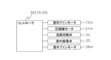
- FIG. 2 is a control block diagram of the air conditioner 1.
- the controller 60 controls various components of the indoor unit 10 and the outdoor unit 20, including the indoor fan motor 12m, the compressor motor 21m, the flow path switching valve 22, the outdoor expansion valve 25, and the outdoor fan motor 26m. It is electrically connected to the equipment so that control signals and information can be exchanged. Also, the controller 60 is communicably connected to various sensors provided in the indoor unit 10 and the outdoor unit 20 .
- the controller 60 starts and stops the operation of the air conditioner 1 and controls the operation of various devices of the air conditioner 1 based on measurement signals from various sensors, commands received by the indoor control unit 19 from the operation remote control, and the like. Control. In addition, the controller 60 can transmit information such as the current operating state and various notifications to the operating remote controller.
- the controller 60 mainly performs cooling operation and heating operation.
- Cooling operation is an operation that cools the temperature of the target space to the set temperature.
- the controller 60 receives an instruction to start the cooling operation and set the temperature from the operation remote controller.
- the controller 60 switches the channel switching valve 22 to the first state.
- the flow switching valve 22 during cooling operation allows the high-temperature, high-pressure gas refrigerant discharged from the compressor 21 to flow to the outdoor heat exchanger 24 .
- the outdoor heat exchanger 24 exchanges heat between the refrigerant and the outdoor air supplied by the outdoor fan 26 .
- the refrigerant cooled by the outdoor heat exchanger 24 is decompressed by the outdoor expansion valve 25 and flows into the indoor heat exchanger 11 . In the indoor heat exchanger 11 , heat exchange is performed between the refrigerant and the air in the target space supplied by the indoor fan 12 .
- the refrigerant warmed by heat exchange in the indoor heat exchanger 11 is sucked into the compressor 21 via the flow path switching valve 22 and the accumulator 23 . Air in the target space cooled by the indoor heat exchanger 11 is blown out from the indoor unit 10 to the target space, thereby cooling the target space.
- Heating operation is an operation that warms the temperature of the target space to the set temperature.
- the controller 60 receives an instruction to start the heating operation and set the temperature from the operating remote controller.
- the controller 60 switches the channel switching valve 22 to the second state.
- the flow path switching valve 22 allows the high-temperature, high-pressure gas refrigerant discharged from the compressor 21 to flow to the indoor heat exchanger 11 .
- heat exchange is performed between the refrigerant and the air in the target space supplied by the indoor fan 12 .
- the refrigerant cooled by the indoor heat exchanger 11 is decompressed by the outdoor expansion valve 25 and flows into the outdoor heat exchanger 24 .
- the outdoor heat exchanger 24 exchanges heat between the refrigerant and the outdoor air supplied by the outdoor fan 26 .
- the refrigerant warmed by heat exchange in the outdoor heat exchanger 24 is sucked into the compressor 21 via the flow path switching valve 22 and the accumulator 23 .
- the air in the target space warmed by the indoor heat exchanger 11 is blown out from the indoor unit 10 to the target space, thereby heating the target space.
- FIG. 3 is an external perspective view of the outdoor heat exchanger 24.
- FIG. 4 is an enlarged perspective sectional view of the outdoor heat exchanger 24.
- FIG. 5 is an enlarged sectional view of the outdoor heat exchanger 24.
- FIG. 6 is a schematic top view of the outdoor heat exchanger 24.
- the outer surface of the outdoor heat exchanger 24 faces the left side, rear side, right side, and front right portion of the rectangular parallelepiped outdoor unit 20 .
- the above-described compressor 21, accumulator 23, outdoor fan 26, and the like are arranged in the space surrounded by the inner surface of the outdoor heat exchanger 24, the above-described compressor 21, accumulator 23, outdoor fan 26, and the like are arranged.
- the outdoor fan 26 blows air forward, the outdoor air flows from the outer surface side to the inner surface side of the outdoor heat exchanger 24 .
- the outdoor heat exchanger 24 has a plurality of flat tubes 243, a plurality of first heat transfer fins 241, and a plurality of second heat transfer fins 242.
- a plurality of flat tubes 243 are arranged along the vertical direction (first direction) intersecting the front-rear direction (longitudinal direction) of the cross section S, and the inside is filled with the refrigerant. flows.
- Each of the plurality of flat tubes 243 has a flat portion 243a serving as a heat transfer surface and a plurality of (nine in FIG. 4) internal flow paths 243b through which a coolant flows.
- the flat tubes 243 are arranged in a plurality of stages so as to be stacked at intervals with the flat portions 243a facing up and down.
- the flat tube 243 is made of aluminum or an aluminum alloy.
- the plurality of first heat transfer fins 241 are arranged behind the plurality of flat tubes 243 in the front-rear direction (longitudinal direction) of the cross section S of the flat tubes 243. It is inserted from (the first end side).
- the multiple first heat transfer fins 241 are in contact with the planar portions 243 a of the multiple flat tubes 243 .
- the multiple first heat transfer fins 241 are positioned on the windward side.
- the first heat transfer fin 241 has a plurality of first insertion portions 241a and first communication portions 241b.
- the plurality of first insertion portions 241a are inserted between adjacent flat tubes 243.
- the first communication portion 241b connects the plurality of first insertion portions 241a outside the rear end (first end) of the cross section S of the flat tube 243 in the front-rear direction (longitudinal direction).
- the first communicating portion 241b extends in the vertical direction (first direction).
- a rib 241c and a fin tab 241d are formed on the first insertion portion 241a.
- the rib 241c is formed by protruding leftward in a U-shaped mountain shape.
- the fin tab 241d is formed by cutting leftward.
- the fin tab 241d maintains the interval (fin pitch L11) between the adjacent first heat transfer fins 241. As shown in FIG.
- a rib 241e and a fin tab 241f are formed in the first communication portion 241b.
- the rib 241e is formed by protruding leftward in a U-shaped mountain shape.
- the fin tab 241f is formed by cutting and raising it leftward.
- the fin tab 241f holds (fin pitch L11) between the adjacent first heat transfer fins 241 .
- the plurality of second heat transfer fins 242 are inserted into the plurality of flat tubes 243 from the front side (second end side) in the front-rear direction (longitudinal direction) of the cross section S of the flat tubes 243 . .
- the multiple second heat transfer fins 242 are in contact with the planar portions 243 a of the multiple flat tubes 243 .
- the plurality of second heat transfer fins 242 are positioned on the leeward side.
- the second heat transfer fins 242 have a plurality of second insertion portions 242a and second communication portions 242b.
- the plurality of second insertion portions 242a are inserted between adjacent flat tubes 243.
- the second communication portion 242b connects the plurality of second insertion portions 242a outside the front end (second end) in the front-rear direction (longitudinal direction) of the cross section S of the flat tube 243 .
- the second communicating portion 242b extends in the vertical direction (first direction).
- a rib 242c and a fin tab 242d are formed on the second insertion portion 242a.
- the rib 242c is formed by protruding leftward in a U-shaped mountain shape.
- the fin tab 242d is formed by cutting and raising it leftward.
- the fin tab 242d maintains the interval (fin pitch L21) between the adjacent second heat transfer fins 242. As shown in FIG.
- a rib 242e and a fin tab 242f are formed in the second communication portion 242b.
- the rib 242e is formed by protruding leftward in a U-shaped mountain shape.
- the fin tab 242f is formed by cutting leftward.
- the fin tabs 242f maintain the interval (fin pitch L21) between the adjacent second heat transfer fins 242. As shown in FIG.
- the first heat transfer fins 241 and the second heat transfer fins 242 are substantially aligned in the front-rear direction.
- the fin pitch L11 of the plurality of first heat transfer fins 241 and the fin pitch L21 of the plurality of second heat transfer fins 242 are equal.
- the width L12 of the first communication portion 241b in the airflow direction is equal to the width L22 of the second communication portion 242b in the airflow direction.
- the distance L3 in the air flow direction between the plurality of first heat transfer fins 241 and the second heat transfer fins 242 is 1 mm or more, and the front-rear direction (longitudinal direction) of the cross section S of the flat tube 243 ) is 20% or less of the length L4.
- Length L4 is, for example, 10 mm to 22 mm.
- first heat transfer fins 241 and the second heat transfer fins 242 are made of clad material.
- the header 244 passes from the compressor 21 side through the first gas refrigerant pipe 43c to the outdoor heat exchanger 24 (in the direction of the solid arrow in FIG. 3) during cooling operation. ) and is split into internal flow paths 243b of the plurality of flat tubes 243 by a header 245, which will be described later, joins and flows into the liquid refrigerant tube 43d. Further, during heating operation, the header 244 transfers the refrigerant that has flowed from the outdoor expansion valve 25 side through the liquid refrigerant pipe 43d into the outdoor heat exchanger 24 (in the direction of the dashed arrow in FIG. to the internal flow path 243b.
- the header 245 directs the refrigerant that has flowed from the compressor 21 side through the first gas refrigerant pipe 43c into the outdoor heat exchanger 24 (in the direction of the solid arrow in FIG.
- the internal flow path 243b is branched.
- the header 245 flows from the outdoor expansion valve 25 side through the liquid refrigerant pipe 43d into the outdoor heat exchanger 24 (in the direction of the dashed arrow in FIG.
- the refrigerant diverted to the internal flow path 243b of 243 is merged and flowed into the first gas refrigerant pipe 43c.
- FIG. 7 is an enlarged sectional view of a conventional outdoor heat exchanger 50. As shown in FIG.
- the distance L3 in the air flow direction between the first heat transfer fin 241 and the second heat transfer fin 242 is set to 1.4 m, and the first heat transfer
- the length L13 of the fins 241 in the wind flow direction and the length L23 of the second heat transfer fins 242 in the wind flow direction were set to 20 mm. Therefore, the length (L3+L13+L23) of the outdoor heat exchanger 24 in the wind flow direction is 41.4 mm.
- the length L5 of the outdoor heat exchanger 50 in the wind flow direction was set to 30 mm.
- Other heat transfer areas, sizes, number of stages of the flat tubes 52 and 243, etc. were made substantially the same.
- FIG. 8 is a graph showing the verification results.
- a graph G1 shows a change in the heating capacity of the outdoor heat exchanger 24 over time.
- a graph G2 shows the change over time in the heating capacity of the outdoor heat exchanger 50 .
- the heating capacities of the outdoor heat exchanger 24 and the outdoor heat exchanger 50 similarly increase until about 800 seconds have elapsed since the start of the heating operation. After that, the outdoor heat exchanger 24 reaches its heating capacity peak when about 1400 seconds have passed. Then, the heating capacity of the outdoor heat exchanger 24 gradually decreases due to frost formation, and the heating capacity is exhausted after about 3200 seconds. On the other hand, the outdoor heat exchanger 50 reaches its heating capacity peak (lower than that of the outdoor heat exchanger 24) after about 1200 seconds. Then, the heating capacity of the outdoor heat exchanger 24 decreases (more rapidly than the outdoor heat exchanger 24) due to frost formation, and the heating capacity is exhausted after about 2800 seconds.
- the outdoor heat exchanger 50 In the outdoor heat exchanger 50, the windward side of the flat tubes 52 is exposed, and since there is no communicating portion of the heat transfer fins 51 on the windward side of the flat tubes 52, dew condensation water cannot be drained well and frost easily forms. . Therefore, it is considered that the outdoor heat exchanger 50 has a lower heating capacity peak than the outdoor heat exchanger 24 and that the heating capacity decreases more rapidly than the outdoor heat exchanger 24 .
- the air conditioner 1 having the outdoor heat exchanger 24 of the present embodiment delays frost formation. Compared to a conventional air conditioner having a heat exchanger 50, the frequency of defrost operation can be reduced and the time during which heating operation is performed can be lengthened.
- the outdoor heat exchanger 24 of this embodiment exchanges heat between refrigerant and air.
- the outdoor heat exchanger 24 includes a plurality of flat tubes 243 , a plurality of first heat transfer fins 241 and a plurality of second heat transfer fins 242 .
- the plurality of flat tubes 243 are arranged along the vertical direction intersecting the front-rear direction of the cross section S, and the refrigerant flows through them.
- the plurality of first heat transfer fins 241 are inserted into the plurality of flat tubes 243 from the rear side of the cross section S of the flat tubes 243 in the front-rear direction.
- the multiple first heat transfer fins 241 are in contact with the multiple flat tubes 243 .
- the multiple first heat transfer fins 241 are positioned on the windward side.
- the plurality of second heat transfer fins 242 are inserted into the plurality of flat tubes 243 from the front side in the front-rear direction of the cross section S of the flat tubes 243 .
- the multiple second heat transfer fins 242 are in contact with the multiple flat tubes 243 .
- the plurality of second heat transfer fins 242 are positioned on the leeward side.
- the first heat transfer fin 241 has a plurality of first insertion portions 241a and first communication portions 241b.
- the plurality of first insertion portions 241a are inserted between adjacent flat tubes 243. As shown in FIG.
- the first communication portion 241b connects the plurality of first insertion portions 241a outside the rear end of the cross section S of the flat tube 243 in the front-rear direction.
- the first communicating portion 241b extends vertically.
- the second heat transfer fins 242 have a plurality of second insertion portions 242a and second communication portions 242b.
- the plurality of second insertion portions 242a are inserted between adjacent flat tubes 243.
- the second communication portion 242b connects the plurality of second insertion portions 242a outside the front end of the cross section S of the flat tube 243 in the front-rear direction.
- the second communication portion 242b extends vertically.
- the first heat transfer fin 241 has a first communicating portion 241b.
- the first communication portion 241b connects the plurality of first insertion portions 241a outside the rear end of the cross section S of the flat tube 243 in the front-rear direction.
- the first communicating portion 241b extends vertically.
- the second heat transfer fins 242 have second communication portions 242b.
- the second communication portion 242b connects the plurality of second insertion portions 242a outside the front end of the cross section S of the flat tube 243 in the front-rear direction.
- the second communication portion 242b extends vertically.
- the outdoor heat exchanger 24 has the first communicating portion 241b of the first heat transfer fin 241 and the second communicating portion 242b of the second heat transfer fin 242 on both sides of the flat tube 243. Drainability can be improved and frost formation can be delayed.
- the distance L3 in the air flow direction between the first heat transfer fins 241 and the second heat transfer fins 242 is 1 mm or more, and the flat tubes 243 is 20% or less of the length L4 in the front-rear direction of the cross section S of .
- the outdoor heat exchanger 24 can prevent the windward ends of the second heat transfer fins 242 from being blocked by frost formation, thereby delaying frost formation.
- the first heat transfer fins 241 and the second heat transfer fins 242 are made of clad material.
- the outdoor heat exchanger 24 can ensure the hydrophilicity of the first heat transfer fins 241 and the second heat transfer fins 242 and improve the drainage performance.
- the width L12 of the first communication portion 241b in the airflow direction is equal to the width L22 of the second communication portion 242b in the airflow direction.
- the width L12 of the first communication portion 241b in the airflow direction may be wider than the width L22 of the second communication portion 242b in the airflow direction.
- the outdoor heat exchanger 24 delays frost formation on the windward end of the first heat transfer fins 241 by moving the windward end of the first heat transfer fins 241 away from the flat tube 243.
- the fin pitch L11 of the plurality of first heat transfer fins 241 and the fin pitch L21 of the plurality of second heat transfer fins 242 are equal.
- the fin pitch L11 of the multiple first heat transfer fins 241 may be wider than the fin pitch L21 of the multiple second heat transfer fins 242 .
- the outdoor heat exchanger 24 can prevent the plurality of first heat transfer fins 241 from being blocked due to frost formation, thereby delaying frost formation.
- the distance L3 in the air flow direction between the first heat transfer fins 241 and the second heat transfer fins 242 is 1 mm or more.
- the distance L3 in the airflow direction between the first heat transfer fins 241 and the second heat transfer fins 242 is equal to or greater than the fin pitch L11 of the plurality of first heat transfer fins 241, and the plurality of heat transfer fins 241 may be equal to or greater than the fin pitch L21 of the second heat transfer fins 242.
- the outdoor heat exchanger 24 can prevent the windward ends of the second heat transfer fins 242 from being blocked by frost formation, thereby delaying frost formation.
- the first heat transfer fins 241 and the second heat transfer fins 242 may have different fin shapes.
- the first heat transfer fins 241 may be formed with waffles
- the second heat transfer fins 242 may be formed with louvers or slits.
- the first heat transfer fins 241 are shaped to have the effect of delaying frost formation, and the second heat transfer fins 242 are shaped to have the effect of promoting heat transfer. Etc., the effects of the first heat transfer fins 241 and the second heat transfer fins 242 can be separated.
- the first heat transfer fins 241 and the second heat transfer fins 242 may have different cutting states.
- the cut state includes whether or not there is a cut.
- a notch such as a louver or a slit may be formed on the front edge of the second heat transfer fin 242 on the windward side.
- the outdoor heat exchanger 24 can promote heat transfer of the second heat transfer fins 242 .
- the outdoor heat exchanger 24 can promote heat transfer at the windward edge of the second heat transfer fins 242 .
Landscapes
- Engineering & Computer Science (AREA)
- Physics & Mathematics (AREA)
- Thermal Sciences (AREA)
- Mechanical Engineering (AREA)
- General Engineering & Computer Science (AREA)
- Geometry (AREA)
- Heat-Exchange Devices With Radiators And Conduit Assemblies (AREA)
- Other Air-Conditioning Systems (AREA)
Priority Applications (5)
| Application Number | Priority Date | Filing Date | Title |
|---|---|---|---|
| EP22876137.5A EP4411305A4 (en) | 2021-09-30 | 2022-09-26 | HEAT EXCHANGER |
| CA3230833A CA3230833A1 (en) | 2021-09-30 | 2022-09-26 | Heat exchanger |
| AU2022355045A AU2022355045B2 (en) | 2021-09-30 | 2022-09-26 | Heat exchanger |
| CN202280065469.6A CN118043623A (zh) | 2021-09-30 | 2022-09-26 | 热交换器 |
| US18/622,224 US20240240877A1 (en) | 2021-09-30 | 2024-03-29 | Heat exchanger |
Applications Claiming Priority (2)
| Application Number | Priority Date | Filing Date | Title |
|---|---|---|---|
| JP2021162282A JP7516335B2 (ja) | 2021-09-30 | 2021-09-30 | 熱交換器 |
| JP2021-162282 | 2021-09-30 |
Related Child Applications (1)
| Application Number | Title | Priority Date | Filing Date |
|---|---|---|---|
| US18/622,224 Continuation US20240240877A1 (en) | 2021-09-30 | 2024-03-29 | Heat exchanger |
Publications (1)
| Publication Number | Publication Date |
|---|---|
| WO2023054270A1 true WO2023054270A1 (ja) | 2023-04-06 |
Family
ID=85782676
Family Applications (1)
| Application Number | Title | Priority Date | Filing Date |
|---|---|---|---|
| PCT/JP2022/035752 Ceased WO2023054270A1 (ja) | 2021-09-30 | 2022-09-26 | 熱交換器 |
Country Status (7)
| Country | Link |
|---|---|
| US (1) | US20240240877A1 (https=) |
| EP (1) | EP4411305A4 (https=) |
| JP (2) | JP7516335B2 (https=) |
| CN (1) | CN118043623A (https=) |
| AU (1) | AU2022355045B2 (https=) |
| CA (1) | CA3230833A1 (https=) |
| WO (1) | WO2023054270A1 (https=) |
Citations (5)
| Publication number | Priority date | Publication date | Assignee | Title |
|---|---|---|---|---|
| JP2003262485A (ja) * | 2002-03-07 | 2003-09-19 | Mitsubishi Electric Corp | フィンチューブ型熱交換器、その製造方法及び冷凍空調装置 |
| JP2013221713A (ja) * | 2012-04-18 | 2013-10-28 | Mitsubishi Electric Corp | 熱交換器およびヒートポンプ装置 |
| JP2015042932A (ja) * | 2013-08-26 | 2015-03-05 | 三菱重工業株式会社 | 熱交換器及び熱交換器の製造方法 |
| WO2018078800A1 (ja) * | 2016-10-28 | 2018-05-03 | 三菱電機株式会社 | 熱交換器及び冷凍サイクル装置 |
| JP2019015410A (ja) | 2017-07-03 | 2019-01-31 | ダイキン工業株式会社 | 熱交換器 |
Family Cites Families (15)
| Publication number | Priority date | Publication date | Assignee | Title |
|---|---|---|---|---|
| US2512540A (en) * | 1945-02-19 | 1950-06-20 | Rue Gas Dev Ltd De | Heat exchanger |
| US3407874A (en) * | 1966-05-19 | 1968-10-29 | John R. Gier Jr. | Fin tube assemblage for heat exchangers |
| JPS50156858U (https=) * | 1974-06-13 | 1975-12-25 | ||
| JPS5510793Y2 (https=) * | 1975-05-30 | 1980-03-08 | ||
| US4546822A (en) * | 1982-11-01 | 1985-10-15 | Nippondenso Co., Ltd. | Heat exchanger with adhesive seals |
| JPH02309194A (ja) * | 1989-05-23 | 1990-12-25 | Matsushita Refrig Co Ltd | フィン付熱交換器 |
| JP2548400B2 (ja) * | 1989-10-13 | 1996-10-30 | 松下冷機株式会社 | 熱交換器の製造方法 |
| JPH11304388A (ja) * | 1998-04-21 | 1999-11-05 | Matsushita Refrig Co Ltd | 熱交換器 |
| EP1485661B1 (en) * | 2002-02-28 | 2010-06-23 | Lg Electronics Inc. | Heat exchanger for refrigerator |
| JP5390417B2 (ja) * | 2010-01-15 | 2014-01-15 | 三菱電機株式会社 | 熱交換器およびその製造方法 |
| JP2014159891A (ja) * | 2013-02-19 | 2014-09-04 | Sharp Corp | 蒸発器及びそれを用いた冷蔵庫 |
| JP5962734B2 (ja) * | 2014-10-27 | 2016-08-03 | ダイキン工業株式会社 | 熱交換器 |
| JP2018054256A (ja) * | 2016-09-30 | 2018-04-05 | ダイキン工業株式会社 | 熱交換ユニット |
| CN109900136B (zh) * | 2017-12-07 | 2021-12-07 | 浙江盾安机械有限公司 | 一种翅片及换热器 |
| JP2021081079A (ja) * | 2019-11-14 | 2021-05-27 | ダイキン工業株式会社 | 熱交換器及び空気調和装置 |
-
2021
- 2021-09-30 JP JP2021162282A patent/JP7516335B2/ja active Active
-
2022
- 2022-09-26 CN CN202280065469.6A patent/CN118043623A/zh active Pending
- 2022-09-26 WO PCT/JP2022/035752 patent/WO2023054270A1/ja not_active Ceased
- 2022-09-26 CA CA3230833A patent/CA3230833A1/en active Pending
- 2022-09-26 EP EP22876137.5A patent/EP4411305A4/en active Pending
- 2022-09-26 AU AU2022355045A patent/AU2022355045B2/en active Active
-
2023
- 2023-07-04 JP JP2023110076A patent/JP7804201B2/ja active Active
-
2024
- 2024-03-29 US US18/622,224 patent/US20240240877A1/en active Pending
Patent Citations (5)
| Publication number | Priority date | Publication date | Assignee | Title |
|---|---|---|---|---|
| JP2003262485A (ja) * | 2002-03-07 | 2003-09-19 | Mitsubishi Electric Corp | フィンチューブ型熱交換器、その製造方法及び冷凍空調装置 |
| JP2013221713A (ja) * | 2012-04-18 | 2013-10-28 | Mitsubishi Electric Corp | 熱交換器およびヒートポンプ装置 |
| JP2015042932A (ja) * | 2013-08-26 | 2015-03-05 | 三菱重工業株式会社 | 熱交換器及び熱交換器の製造方法 |
| WO2018078800A1 (ja) * | 2016-10-28 | 2018-05-03 | 三菱電機株式会社 | 熱交換器及び冷凍サイクル装置 |
| JP2019015410A (ja) | 2017-07-03 | 2019-01-31 | ダイキン工業株式会社 | 熱交換器 |
Non-Patent Citations (1)
| Title |
|---|
| See also references of EP4411305A4 |
Also Published As
| Publication number | Publication date |
|---|---|
| JP7804201B2 (ja) | 2026-01-22 |
| AU2022355045A1 (en) | 2024-05-09 |
| US20240240877A1 (en) | 2024-07-18 |
| EP4411305A4 (en) | 2025-01-22 |
| JP2023129751A (ja) | 2023-09-15 |
| JP7516335B2 (ja) | 2024-07-16 |
| AU2022355045B2 (en) | 2025-09-04 |
| EP4411305A1 (en) | 2024-08-07 |
| JP2023051525A (ja) | 2023-04-11 |
| CA3230833A1 (en) | 2023-04-06 |
| CN118043623A (zh) | 2024-05-14 |
Similar Documents
| Publication | Publication Date | Title |
|---|---|---|
| JP5196043B2 (ja) | 熱交換器および空気調和機 | |
| JP5177306B2 (ja) | 熱交換器及び空気調和機 | |
| KR101451056B1 (ko) | 열교환기 및 공기 조화기 | |
| JP5934933B2 (ja) | 室外熱交換器 | |
| JP6701371B2 (ja) | 熱交換器及び冷凍サイクル装置 | |
| WO2016139730A1 (ja) | フィンアンドチューブ型熱交換器及びこれを備えた冷凍サイクル装置 | |
| JP4196974B2 (ja) | 空気調和機 | |
| US20250164195A1 (en) | Heat exchanger and refrigeration cycle apparatus including the same | |
| JP6678413B2 (ja) | 空気調和機 | |
| JP2012154493A (ja) | 熱交換器及び空気調和機 | |
| JP2012154492A (ja) | 熱交換器及び空気調和機 | |
| WO2021095452A1 (ja) | 熱交換器及び空気調和装置 | |
| JP7804201B2 (ja) | 熱交換器 | |
| JP6548824B2 (ja) | 熱交換器および冷凍サイクル装置 | |
| KR100660967B1 (ko) | 히트 펌프식 공기조화기의 실외 열교환기 | |
| KR20050023759A (ko) | 착상 지연용 열교환기 | |
| WO2025079135A1 (ja) | 熱交換器、冷凍サイクル装置および冷凍サイクルシステム | |
| KR20050102526A (ko) | 냉난방 겸용 에어콘의 열교환기 구조 |
Legal Events
| Date | Code | Title | Description |
|---|---|---|---|
| 121 | Ep: the epo has been informed by wipo that ep was designated in this application |
Ref document number: 22876137 Country of ref document: EP Kind code of ref document: A1 |
|
| WWE | Wipo information: entry into national phase |
Ref document number: 3230833 Country of ref document: CA |
|
| WWE | Wipo information: entry into national phase |
Ref document number: 202280065469.6 Country of ref document: CN |
|
| WWE | Wipo information: entry into national phase |
Ref document number: 202417032120 Country of ref document: IN |
|
| WWE | Wipo information: entry into national phase |
Ref document number: AU2022355045 Country of ref document: AU |
|
| WWE | Wipo information: entry into national phase |
Ref document number: 2022876137 Country of ref document: EP |
|
| NENP | Non-entry into the national phase |
Ref country code: DE |
|
| ENP | Entry into the national phase |
Ref document number: 2022355045 Country of ref document: AU Date of ref document: 20220926 Kind code of ref document: A |
|
| ENP | Entry into the national phase |
Ref document number: 2022876137 Country of ref document: EP Effective date: 20240430 |