WO2023053973A1 - 電動弁制御装置および電動弁装置、ならびに、電動弁の制御方法 - Google Patents
電動弁制御装置および電動弁装置、ならびに、電動弁の制御方法 Download PDFInfo
- Publication number
- WO2023053973A1 WO2023053973A1 PCT/JP2022/034456 JP2022034456W WO2023053973A1 WO 2023053973 A1 WO2023053973 A1 WO 2023053973A1 JP 2022034456 W JP2022034456 W JP 2022034456W WO 2023053973 A1 WO2023053973 A1 WO 2023053973A1
- Authority
- WO
- WIPO (PCT)
- Prior art keywords
- motor
- voltage
- rotation
- rotor
- operated valve
- Prior art date
- Legal status (The legal status is an assumption and is not a legal conclusion. Google has not performed a legal analysis and makes no representation as to the accuracy of the status listed.)
- Ceased
Links
Images


Classifications
-
- H—ELECTRICITY
- H02—GENERATION; CONVERSION OR DISTRIBUTION OF ELECTRIC POWER
- H02P—CONTROL OR REGULATION OF ELECTRIC MOTORS, ELECTRIC GENERATORS OR DYNAMO-ELECTRIC CONVERTERS; CONTROLLING TRANSFORMERS, REACTORS OR CHOKE COILS
- H02P8/00—Arrangements for controlling dynamo-electric motors rotating step by step
- H02P8/34—Monitoring operation
-
- F—MECHANICAL ENGINEERING; LIGHTING; HEATING; WEAPONS; BLASTING
- F16—ENGINEERING ELEMENTS AND UNITS; GENERAL MEASURES FOR PRODUCING AND MAINTAINING EFFECTIVE FUNCTIONING OF MACHINES OR INSTALLATIONS; THERMAL INSULATION IN GENERAL
- F16K—VALVES; TAPS; COCKS; ACTUATING-FLOATS; DEVICES FOR VENTING OR AERATING
- F16K31/00—Actuating devices; Operating means; Releasing devices
- F16K31/44—Mechanical actuating means
- F16K31/50—Mechanical actuating means with screw-spindle or internally threaded actuating means
- F16K31/504—Mechanical actuating means with screw-spindle or internally threaded actuating means the actuating means being rotable, rising, and having internal threads which co-operate with threads on the outside of the valve body
-
- F—MECHANICAL ENGINEERING; LIGHTING; HEATING; WEAPONS; BLASTING
- F16—ENGINEERING ELEMENTS AND UNITS; GENERAL MEASURES FOR PRODUCING AND MAINTAINING EFFECTIVE FUNCTIONING OF MACHINES OR INSTALLATIONS; THERMAL INSULATION IN GENERAL
- F16K—VALVES; TAPS; COCKS; ACTUATING-FLOATS; DEVICES FOR VENTING OR AERATING
- F16K1/00—Lift valves or globe valves, i.e. cut-off apparatus with closure members having at least a component of their opening and closing motion perpendicular to the closing faces
- F16K1/32—Details
- F16K1/34—Cutting-off parts, e.g. valve members, seats
- F16K1/36—Valve members
- F16K1/38—Valve members of conical shape
-
- F—MECHANICAL ENGINEERING; LIGHTING; HEATING; WEAPONS; BLASTING
- F16—ENGINEERING ELEMENTS AND UNITS; GENERAL MEASURES FOR PRODUCING AND MAINTAINING EFFECTIVE FUNCTIONING OF MACHINES OR INSTALLATIONS; THERMAL INSULATION IN GENERAL
- F16K—VALVES; TAPS; COCKS; ACTUATING-FLOATS; DEVICES FOR VENTING OR AERATING
- F16K27/00—Construction of housing; Use of materials therefor
- F16K27/02—Construction of housing; Use of materials therefor of lift valves
- F16K27/029—Electromagnetically actuated valves
-
- F—MECHANICAL ENGINEERING; LIGHTING; HEATING; WEAPONS; BLASTING
- F16—ENGINEERING ELEMENTS AND UNITS; GENERAL MEASURES FOR PRODUCING AND MAINTAINING EFFECTIVE FUNCTIONING OF MACHINES OR INSTALLATIONS; THERMAL INSULATION IN GENERAL
- F16K—VALVES; TAPS; COCKS; ACTUATING-FLOATS; DEVICES FOR VENTING OR AERATING
- F16K31/00—Actuating devices; Operating means; Releasing devices
- F16K31/02—Actuating devices; Operating means; Releasing devices electric; magnetic
- F16K31/04—Actuating devices; Operating means; Releasing devices electric; magnetic using a motor
- F16K31/046—Actuating devices; Operating means; Releasing devices electric; magnetic using a motor with electric means, e.g. electric switches, to control the motor or to control a clutch between the valve and the motor
-
- H—ELECTRICITY
- H02—GENERATION; CONVERSION OR DISTRIBUTION OF ELECTRIC POWER
- H02K—DYNAMO-ELECTRIC MACHINES
- H02K16/00—Machines with more than one rotor or stator
- H02K16/04—Machines with one rotor and two stators
-
- H—ELECTRICITY
- H02—GENERATION; CONVERSION OR DISTRIBUTION OF ELECTRIC POWER
- H02P—CONTROL OR REGULATION OF ELECTRIC MOTORS, ELECTRIC GENERATORS OR DYNAMO-ELECTRIC CONVERTERS; CONTROLLING TRANSFORMERS, REACTORS OR CHOKE COILS
- H02P6/00—Arrangements for controlling synchronous motors or other dynamo-electric motors using electronic commutation dependent on the rotor position; Electronic commutators therefor
- H02P6/14—Electronic commutators
- H02P6/16—Circuit arrangements for detecting position
- H02P6/18—Circuit arrangements for detecting position without separate position detecting elements
- H02P6/182—Circuit arrangements for detecting position without separate position detecting elements using back-emf in windings
-
- Y—GENERAL TAGGING OF NEW TECHNOLOGICAL DEVELOPMENTS; GENERAL TAGGING OF CROSS-SECTIONAL TECHNOLOGIES SPANNING OVER SEVERAL SECTIONS OF THE IPC; TECHNICAL SUBJECTS COVERED BY FORMER USPC CROSS-REFERENCE ART COLLECTIONS [XRACs] AND DIGESTS
- Y02—TECHNOLOGIES OR APPLICATIONS FOR MITIGATION OR ADAPTATION AGAINST CLIMATE CHANGE
- Y02B—CLIMATE CHANGE MITIGATION TECHNOLOGIES RELATED TO BUILDINGS, e.g. HOUSING, HOUSE APPLIANCES OR RELATED END-USER APPLICATIONS
- Y02B30/00—Energy efficient heating, ventilation or air conditioning [HVAC]
- Y02B30/70—Efficient control or regulation technologies, e.g. for control of refrigerant flow, motor or heating
Definitions
- the present invention relates to a motor-operated valve control device, a motor-operated valve device having the motor-operated valve control device, and a method for controlling the motor-operated valve.
- Patent Document 1 discloses an example of a conventional electric valve. Such an electrically operated valve is incorporated into the refrigeration cycle of an air conditioner.
- the electric valve has a valve body, a valve body, and a stepping motor for moving the valve body.
- a stepping motor has a rotor and a stator. When a pulse is input to the stepping motor, the rotor rotates. The valve body moves according to the rotation of the rotor. When the rotor is at the reference position, a movable stopper that rotates together with the rotor comes into contact with a fixed stopper that is fixed to the valve body, thereby restricting rotation of the rotor in the first direction.
- the motor-operated valve is controlled by the motor-operated valve controller.
- the motor-operated valve controller pulses the stepping motor to rotate the rotor in a first direction and position the rotor at a reference position.
- the number of pulses input to the stepping motor is sufficient for the movable stopper to come into contact with the fixed stopper (hereinafter referred to as "initialization number").
- the electric valve controller inputs pulses to the stepping motor until the number of pulses input to the stepping motor reaches the initialization number. Therefore, the motor-operated valve control device may receive a pulse even after the rotor is positioned at the reference position, and the initialization operation takes a long time. Further, when a pulse is input to the stepping motor after the rotor is positioned at the reference position, the movable stopper repeatedly collides with the fixed stopper, generating noise. In particular, when the position of the rotor immediately before the initialization operation is close to the reference position, the noise is generated for a long time.
- the present invention provides a motor-operated valve control device that can reduce noise by shortening the time required for the initialization operation of the motor-operated valve, a motor-operated valve device having the motor-operated valve control device, and a method of controlling the motor-operated valve. intended to
- the inventors measured the voltage (voltage electromagnetically induced in the stator) generated in the stator by the rotation of the rotor during the initialization operation using a plurality of motor-operated valves, and diligently studied the measurement results. As a result, the inventors found a difference between the waveform of the voltage before the rotation of the rotor was restricted by the stopper mechanism and the waveform of the voltage after the rotation of the rotor was restricted by the stopper mechanism. reached.
- the motor-operated valve control device includes a valve body having a valve seat, a rotor rotatable with respect to the valve body, a stator that forms a stepping motor together with the rotor, and a stator facing the valve seat, the rotor being oriented in a first direction.
- a motor-operated valve control for controlling a motor-operated valve having a valve body that moves toward the valve seat when rotated, and a stopper mechanism that restricts rotation of the rotor in the first direction when the rotor is at a reference position.
- a rotation control unit for supplying a drive current to the stator to rotate the rotor in the first direction; a voltage acquisition unit for acquiring a voltage generated in the stator by the rotation of the rotor; (ii) the amplitude of a wave periodically observed in the voltage waveform; and (iii) the periodicity of a new wave different from the periodically observed wave in the voltage waveform.
- a state determination unit that determines whether or not the motor-operated valve is in a rotation restricted state in which rotation of the rotor in the first direction is restricted by the stopper mechanism, based on at least one of: , has
- the rotation control unit stops supplying the drive current to the stator when the state determination unit determines that the motor-operated valve is in the rotation restricted state.
- the stator has an A-phase stator and a B-phase stator, and the voltage acquisition unit detects the voltage generated in one of the A-phase stator and the B-phase stator when the rotation control unit supplies a drive current to the other. is preferred.
- the valve body faces the valve seat, and when the rotor rotates in the first direction, it is pushed toward the valve seat via a coil spring, and the reference position is such that the rotor is positioned against the valve seat and the valve body. is at a position further rotated in the first direction than the valve closing position where the rotor is in contact with It is preferable to determine an intermediate state between the closed valve position and the reference position.
- the motor-operated valve control device includes a valve body having a valve seat, a rotor rotatable with respect to the valve body, a stator that forms a stepping motor together with the rotor, and a stator facing the valve seat, the rotor being oriented in a first direction.
- a motor-operated valve control for controlling a motor-operated valve having a valve body that moves toward the valve seat when rotated, and a stopper mechanism that restricts rotation of the rotor in the first direction when the rotor is at a reference position.
- a rotation control unit for supplying a drive current to the stator to rotate the rotor in the first direction; a current acquisition unit for acquiring a current generated in the stator by the rotation of the rotor; (ii) the amplitude of a periodically observed wave in the current waveform; and (iii) the periodicity of a new wave different from the periodically observed wave in the current waveform.
- a state determination unit that determines whether or not the motor-operated valve is in a rotation restricted state in which rotation of the rotor in the first direction is restricted by the stopper mechanism, based on at least one of: , has
- the motor-operated valve device has the motor-operated valve and the motor-operated valve control device.
- a method of controlling a motor-operated valve comprises: a valve body having a valve seat; a rotor rotatable with respect to the valve body; a stator that forms a stepping motor together with the rotor; and a stopper mechanism for restricting rotation of the rotor in the first direction when the rotor is in a reference position.
- a method of controlling a motor-operated valve comprises: a valve body having a valve seat; a rotor rotatable with respect to the valve body; a stator that forms a stepping motor together with the rotor; and a stopper mechanism for restricting rotation of the rotor in the first direction when the rotor is in a reference position.
- to supply a driving current to the stator to rotate the rotor in the first direction obtain a current generated in the stator by the rotation of the rotor, (i) the area of the waveform of the current, (ii) the based on at least one of: the amplitude of waves periodically observed in the current waveform; and (iii) the periodic appearance of new waves different from the waves periodically observed in the current waveform. to determine whether or not the motor-operated valve is in a rotation restricted state in which rotation of the rotor in the first direction is restricted by the stopper mechanism.
- an electric valve control device includes: A valve body having a valve seat, a rotor rotatable with respect to the valve body, a stator that forms a stepping motor together with the rotor, and a stator that faces the valve seat and moves to the valve seat when the rotor rotates in a first direction.
- a motor-operated valve control device for controlling a motor-operated valve having a valve body that moves toward and a stopper mechanism that restricts rotation of the rotor in the first direction when the rotor is at a reference position, a rotation control unit for inputting a pulse to the stepping motor to rotate the rotor in the first direction; a voltage acquisition unit that acquires a voltage generated in the stator by the rotation of the rotor; Based on the degree of difference between the voltage waveform and the voltage reference waveform, it is determined whether or not the motor-operated valve is in a first rotation restriction state in which rotation of the rotor in the first direction is restricted. and a state determination unit.
- the reference waveform is the pulse that causes the stepping motor to rotate the rotor in the first direction in a state in which the motor-operated valve is allowed to rotate the rotor in the first direction (hereinafter, "first direction pulse"). ) is input, including a first rotation permissible state waveform set based on the waveform of the voltage, The state determination unit provides a difference index indicating the degree of difference between the first rotation permissible state waveform and the voltage waveform acquired by the voltage acquisition unit in response to the input of the first direction pulse to the stepping motor. It is preferable to determine whether or not the motor-operated valve is in the first rotation restriction state based on a comparison result between the difference index value and the difference determination value.
- the reference waveform is the pulse that causes the stepping motor to rotate the rotor in the first direction in a state in which the motor-operated valve is restricted from rotating the rotor in the first direction (hereinafter referred to as the "first direction pulse").
- the state determination unit provides a difference index indicating the degree of difference between the first rotation restriction state waveform and the voltage waveform acquired by the voltage acquisition unit in response to the input of the first direction pulse to the stepping motor. It is preferable to determine whether or not the motor-operated valve is in the first rotation restriction state based on a comparison result between the difference index value and the difference determination value.
- first direction pulse The pulse for rotating the rotor in the first direction
- first direction pulse The pulse for rotating the rotor in the first direction
- first direction pulse a first rotation permissible state waveform set based on the waveform of the voltage when the A first rotation restriction state that is set based on the waveform of the voltage when the first direction pulse is input to the stepping motor while the motor-operated valve restricts rotation of the rotor in the first direction.
- the state determination unit A difference index value indicating the degree of difference between the first rotation permissible state waveform and the waveform of the voltage acquired by the voltage acquisition unit in response to the input of the first direction pulse to the stepping motor (hereinafter referred to as “second (referred to as “one rotation permissible state difference index value”), Difference index value indicating the degree of difference between the first rotation restriction state waveform and the waveform of the voltage acquired by the voltage acquisition unit in response to the input of the first direction pulse to the stepping motor (hereinafter referred to as “second (referred to as “single rotation regulation state difference index value”), A comparison result between the first rotation permissible state dissimilarity index value and the first rotation permissible state dissimilarity determination value, and a comparison result between the first rotation restriction state dissimilarity index value and the first rotation restriction state dissimilarity determination value. and, preferably, whether or not the motor-operated valve is in the first rotation restriction state is determined.
- the rotation control section stops inputting the pulse to the stepping motor when the state determination section determines that the motor-operated valve is in the first rotation restriction state.
- the reference waveform is the pulse that causes the stepping motor to rotate the rotor in the second direction in a state where the motor-operated valve is allowed to rotate the rotor in the second direction (hereinafter referred to as the "second direction pulse").
- the second direction pulse is input, including a second rotation permissible state waveform set based on the waveform of the voltage
- the rotation control unit inputs the pulse to the stepping motor to rotate the rotor in the second direction;
- the state determination unit provides a difference index indicating the degree of difference between the second rotation permissible state waveform and the voltage waveform acquired by the voltage acquisition unit in response to the input of the second direction pulse to the stepping motor.
- second rotation permissible state dissimilarity index value a value (hereinafter referred to as "second rotation permissible state dissimilarity index value"), and based on the result of comparison between the second rotation permissible state dissimilarity index value and the second rotation permissible state dissimilarity judgment value, determining whether the motor-operated valve is in a second rotation restriction state in which rotation of the rotor in the second direction is restricted;
- the rotation control unit stops inputting the pulse to the stepping motor when the state determination unit determines that the motor-operated valve is in the second rotation restriction state;
- the rotation control unit determines that the stepping motor to rotate the rotor in the first direction.
- a data table in which the reference waveform is set with respect to the first-direction pulse and in which a time and a reference voltage at that time are associated; the voltage acquiring unit acquires the voltage in time series when the first direction pulse is input to the stepping motor; When the voltage acquisition unit acquires the voltage at the acquisition time corresponding to the input of the first direction pulse, the state determination unit sets the voltage and the first direction pulse input to the stepping motor.
- the state determination unit calculates the dissimilarity index value by adding together the plurality of first intermediate values calculated using the voltage acquired by the voltage acquisition unit in response to the input of the first direction pulse. preferably.
- a data table in which the reference waveform is set with respect to the second direction pulse and in which the time and the reference voltage at the time are associated; the voltage acquisition unit acquires the voltage in time series when the second direction pulse is input to the stepping motor; When the voltage acquisition unit acquires the voltage at the acquisition time corresponding to the input of the second direction pulse, the state determination unit sets the voltage and the second direction pulse input to the stepping motor.
- the state determination unit calculates the dissimilarity index value by adding together the plurality of second intermediate values calculated using the voltage acquired by the voltage acquisition unit in response to the input of the second direction pulse. preferably.
- the state determination unit sums the plurality of first intermediate values calculated using the voltages acquired by the voltage acquisition unit in a part of the period from the beginning to the end of the first direction pulse, and calculates the difference Calculate the degree index value, It is preferable that a voltage component related to back electromotive force due to the inductance of the stator included in the voltage in the part of the period is smaller than a voltage component included in the voltage related to electromagnetic induction due to rotation of the rotor.
- the state determination unit sums the plurality of second intermediate values calculated using the voltages acquired by the voltage acquisition unit in a part of the period from the start to the end of the second direction pulse, and calculates the difference. Calculate the degree index value, It is preferable that a voltage component related to back electromotive force due to the inductance of the stator included in the voltage in the part of the period is smaller than a voltage component included in the voltage related to electromagnetic induction due to rotation of the rotor.
- the start pattern number is determined based on the pattern number of the first direction pulse corresponding to the voltage waveform used for the determination. Acquired, It is preferable that, when the rotation control section rotates the rotor in the reference position in the second direction, the input starts from the pulse having the same pattern number as the start pattern number.
- the first rotation restriction state waveform is set for the first direction pulse based on a plurality of voltage waveforms obtained in advance in the motor-operated valve combined with the motor-operated valve control device; It is preferable that one said first rotation restriction state waveform is set for one said first direction pulse.
- the first rotation restriction state waveform is set for the first direction pulse based on a plurality of voltage waveforms obtained in advance in the plurality of motor-operated valves; a plurality of the first rotation restriction state waveforms different from each other are set for one of the first direction pulses; the number of said first rotation restriction state waveforms set for one said first direction pulse is the same as the number of said pulse patterns;
- the first rotation restriction state waveform set for one of the first direction pulses includes a plurality of different pulses corresponding to the timing at which the rotation of the rotor in the first direction is restricted by the stopper mechanism. It is preferable to set based on the waveform of the voltage acquired in the motor operated valve.
- the stator has an A-phase stator and a B-phase stator
- the voltage acquisition unit acquires the voltage generated in one of the A-phase stator and the B-phase stator when the rotation control unit supplies drive current to only one of the A-phase stator and the B-phase stator in response to the input of the pulse to the stepping motor. preferably.
- the valve body faces the valve seat and is pushed toward the valve seat via a coil spring when the rotor rotates in the first direction; It is preferable that the reference position is a position where the rotor rotates further in the first direction than the valve closing position where the valve body contacts the valve seat.
- an electric valve control device includes: A valve body having a valve seat, a rotor rotatable with respect to the valve body, a stator that forms a stepping motor together with the rotor, and a stator that faces the valve seat and moves to the valve seat when the rotor rotates in a first direction.
- a motor-operated valve control device for controlling a motor-operated valve having a valve body that moves toward and a stopper mechanism that restricts rotation of the rotor in the first direction when the rotor is at a reference position, a rotation control unit for inputting a pulse to the stepping motor to rotate the rotor in the first direction; a current acquisition unit that acquires a current generated in the stator by the rotation of the rotor; Based on the degree of difference between the waveform of the current and the reference waveform of the current, it is determined whether the motor-operated valve is in a first rotation restriction state in which rotation of the rotor in the first direction is restricted. and a state determination unit.
- a motor operated valve device includes: The motor-operated valve and the motor-operated valve control device are provided.
- a valve body having a valve seat, a rotor rotatable with respect to the valve body, a stator that forms a stepping motor together with the rotor, and a stator that faces the valve seat and moves to the valve seat when the rotor rotates in a first direction.
- a control method for a motor-operated valve having a valve body that moves toward and a stopper mechanism that restricts rotation of the rotor in the first direction when the rotor is at a reference position, inputting a pulse to the stepping motor to rotate the rotor in the first direction; Obtaining the voltage generated in the stator by the rotation of the rotor; Based on the degree of difference between the voltage waveform and the voltage reference waveform, it is determined whether or not the motor-operated valve is in a first rotation restriction state in which rotation of the rotor in the first direction is restricted.
- a valve body having a valve seat, a rotor rotatable with respect to the valve body, a stator that forms a stepping motor together with the rotor, and a stator that faces the valve seat and moves to the valve seat when the rotor rotates in a first direction.
- a control method for a motor-operated valve having a valve body that moves toward and a stopper mechanism that restricts rotation of the rotor in the first direction when the rotor is at a reference position, inputting a pulse to the stepping motor to rotate the rotor in the first direction; Obtaining the current generated in the stator by the rotation of the rotor; Based on the degree of difference between the waveform of the current and the reference waveform of the current, it is determined whether the motor-operated valve is in a first rotation restriction state in which rotation of the rotor in the first direction is restricted.
- pulses are input to the stepping motor to rotate the rotor in the first direction. Acquire the voltage produced in the stator by the rotation of the rotor. Then, based on the degree of difference between the voltage waveform and the voltage reference waveform, it is determined whether or not the motor-operated valve is in the first rotation restriction state in which rotation of the rotor in the first direction is restricted.
- pulses are input to the stepping motor to rotate the rotor in the first direction. Acquire the current induced in the stator by the rotation of the rotor. Then, based on the degree of difference between the waveform of the current and the reference waveform of the current, it is determined whether or not the motor-operated valve is in the first rotation restricted state in which rotation of the rotor in the first direction is restricted.
- the rotor of the motor-operated valve that can operate normally is at the reference position when it is determined that the motor-operated valve is in the first rotation restriction state. Therefore, by stopping the rotation of the rotor in the first direction when it is determined that the motor-operated valve is in the first rotation restriction state, the time required for the initialization operation can be shortened. Moreover, it is possible to suppress the generation of noise for a long time after the rotor is positioned at the reference position. Also, the state of the motor-operated valve is determined based on the degree of difference between the waveforms. Therefore, the state of the motor-operated valve can be determined with higher accuracy than the configuration in which the state of the motor-operated valve is determined based on the area of the waveform or the maximum amplitude of the waveform.
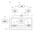
- FIG. 1 is a block diagram of an air conditioner system having an electric valve device
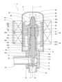
- FIG. FIG. 2 is a cross-sectional view of the motor-operated valve device of FIG. 1
- FIG. 3 is a view showing a valve stem holder included in the motor-operated valve device of FIG. 2
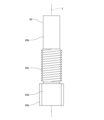
- FIG. 3 is a side view of a guide bush included in the motor-operated valve device of FIG. 2
- 3 is a view showing a stopper member included in the motor operated valve device of FIG. 2
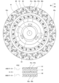
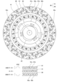
- FIG. FIG. 3 is a plan view of a valve shaft holder, a stopper member, a rotor, and a stator of the motor-operated valve device of FIG.
- FIG. 4 is a diagram schematically showing the positional relationship between the magnetic poles of the rotor and the pole teeth of the stator (when pulse P[1] is input);
- FIG. 4 is a diagram schematically showing the positional relationship between the magnetic poles of the rotor and the pole teeth of the stator (when pulse P[2] is input);
- FIG. 4 is a diagram schematically showing the positional relationship between the magnetic poles of the rotor and the pole teeth of the stator (when pulse P[3] is input);
- FIG. 4 is a diagram schematically showing the positional relationship between the magnetic poles of the rotor and the pole teeth of the stator (when pulse P[4] is input);
- FIG. 4 is a diagram schematically showing the positional relationship between the magnetic poles of the rotor and the pole teeth of the stator (when pulse P[5] is input);
- FIG. 4 is a diagram schematically showing the positional relationship between the magnetic poles of the rotor and the pole teeth of the stator (when pulse P[6] is input);
- FIG. 4 is a diagram schematically showing the positional relationship between the magnetic poles of the rotor and the pole teeth of the stator (when pulse P[7] is input);
- FIG. 4 is a diagram schematically showing the positional relationship between the magnetic poles of the rotor and the pole teeth of the stator (when pulse P[7] is input);
- FIG. 4 is a diagram schematically showing the positional relationship between the magnetic poles of the rotor and the pole teeth of the stator (when pulse P[8] is input);
- FIG. 5 is a diagram showing an example of voltage waveforms generated in the stator due to the rotation of the rotor in the initialization operation of the motor-operated valve device;
- FIG. 17 is an enlarged view of a part of the voltage waveform of FIG. 16;
- FIG. 17 is an enlarged view of another portion of the voltage waveform of FIG. 16;
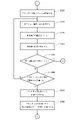
- 3 is a flow chart showing an example of an initialization operation executed by a computer included in the motor-operated valve device of FIG. 2;
- FIG. 4 is a diagram showing an example of waveforms including a standard voltage waveform (first rotation permissible state waveform);
- FIG. 4 is a diagram showing an example of waveforms including a standard voltage waveform (first rotation restriction state waveform #1);
- FIG. 12 is a diagram (part 2) showing an example of waveforms including a standard voltage waveform (first rotation restriction state waveform #2);
- FIG. 10 is a diagram showing an example of waveforms including a standard voltage waveform (first rotation restriction state waveform #3); It is a figure which shows the example of a waveform containing the standard waveform (1st rotation control state waveform #4) of a voltage (part 4). It is a figure which shows the example of a waveform containing the standard waveform (first rotation control state waveform #5) of a voltage (No. 5).
- FIG. 5 shows an example of waveforms including a standard voltage waveform (first rotation restriction state waveform #1);
- FIG. 12 is a diagram (part 2) showing an example of waveforms including a standard voltage waveform (first rotation restriction state waveform #2);
- FIG. 10 is a diagram showing an example of waveforms including
- FIG. 11 is a diagram showing an example of waveforms including a standard voltage waveform (first rotation restriction state waveform #6) (No. 6);
- FIG. 11 is a diagram showing an example of waveforms including a standard voltage waveform (first rotation restriction state waveform #7) (No. 7);
- FIG. 11 is a diagram showing an example of waveforms including a standard voltage waveform (first rotation restriction state waveform #8) (No. 8);
- It is a figure which shows the example of the data table (1st permissible rotation state table) of the standard waveform of a voltage.
- FIG. 7 is a flow chart showing operation example 2 of the electric valve control device according to the embodiment of the present invention;
- FIG. FIG. 33 is a flow chart showing operation example 2 of the electric valve control device according to the embodiment of the
- the electric valve device will be described below with reference to FIGS. 1 to 19.
- the motor-operated valve device 1 is used, for example, as a flow control valve that controls the flow rate of refrigerant in the refrigeration cycle of an air conditioner.
- FIG. 1 is a block diagram of an air conditioner system having an electric valve device.
- 2 is a cross-sectional view of the motor-operated valve device of FIG. 1.
- FIG. FIG. 2 schematically shows a stator and an electric valve control device.
- FIG. 3 is a view showing a valve stem holder included in the motor-operated valve device of FIG. 2.
- FIG. 3A is a perspective view of the valve stem holder, and
- FIG. 3B is a plan view of the valve stem holder.
- 4 is a side view of a guide bush included in the motor-operated valve device of FIG. 2.
- FIG. FIG. 5 is a diagram showing a stopper member included in the electric valve device of FIG. 2.
- FIG. 5A is a perspective view of the stopper member, and FIG.
- FIG. 5B is a plan view of the stopper member.
- 6 is a plan view of a valve shaft holder, a stopper member, a rotor, and a stator of the motor-operated valve device of FIG. 2.
- FIG. FIG. 6 schematically shows the stator. 6 schematically shows the magnetic poles of the rotor.
- FIG. 7 is a diagram illustrating a computer, a motor driver, and a stepping motor that the motor-operated valve device of FIG. 2 has.
- FIG. 7A schematically shows connections between a computer, a motor driver, and a stepping motor that the electric valve control device has.
- FIG. 7B shows an example of the correspondence between the pulses and the drive current supplied to the stator by the motor driver.
- FIG. 16 is a diagram showing an example of voltage waveforms generated in the stator due to the rotation of the rotor in the initialization operation of the motor-operated valve device.
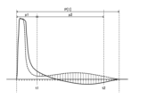
- FIG. 17 is an enlarged view of a part (period T1) of the voltage waveform in FIG.
- FIG. 18 is an enlarged view of another portion (period T7) of the voltage waveform in FIG. 19 is a flow chart showing an example of an initialization operation executed by a computer of the motor-operated valve device of FIG. 2.
- FIG. 1 shows an example of an air conditioning system 100 mounted on a vehicle.
- This air conditioning system 100 has a compressor 101 , a condenser 102 , a motor-operated valve device 1 (a motor-operated valve 5 ) and an evaporator 103 which are connected in order via a pipe 105 .
- the electric valve device 1 is an expansion valve.
- the air conditioner system 100 has an air conditioner control device 110 .
- the air conditioner control device 110 is communicably connected to the electric valve device 1 .
- the air conditioner control device 110 controls the flow rate of refrigerant flowing through the pipe 105 using the electric valve device 1 .
- the motor-operated valve device 1 has a motor-operated valve 5 and a motor-operated valve control device 70 .
- the electric valve 5 has a valve body 10, a can 20, a valve body 30, a drive mechanism 40, and a stator 60.
- the valve body 10 has a body member 11 and a connection member 13.
- the body member 11 has a cylindrical shape.
- the body member 11 has a valve chamber 14 .
- a first conduit 15 and a second conduit 16 are joined to the body member 11 .
- the first conduit 15 is arranged along a direction perpendicular to the axis L (horizontal direction in FIG. 2) and connected to the valve chamber 14 .
- the second conduit 16 is arranged along the direction of the axis L (vertical direction in FIG. 2) and is connected to the valve chamber 14 via the valve port 17 .
- the valve port 17 is surrounded by an annular valve seat 18 in the valve chamber 14 .
- the body member 11 has a circular fitting hole 11a.
- the fitting hole 11 a is arranged on the upper end surface of the body member 11 .
- the inner peripheral surface of the fitting hole 11a has a flat surface 11d facing leftward in FIG.
- a through hole 11b communicating with the valve chamber 14 is provided in the bottom surface of the fitting hole 11a.
- the connection member 13 has an annular plate shape. The inner peripheral edge of the connection member 13 is joined to the upper end portion of the main body member 11 .
- the body member 11 and the connection member 13 are made of metal such as aluminum alloy, stainless steel, or brass.
- the can 20 is made of metal such as stainless steel.
- the can 20 has a cylindrical shape.
- the can 20 is open at its lower end and closed at its upper end.
- a lower end portion of the can 20 is joined to the outer peripheral edge of the connecting member 13 .
- the valve body 30 has a first shaft portion 31 , a second shaft portion 32 and a valve portion 33 .
- the first shaft portion 31 has a cylindrical shape.
- the second shaft portion 32 has a cylindrical shape.
- the diameter of the second shaft portion 32 is smaller than the diameter of the first shaft portion 31 .
- the second shaft portion 32 is coaxially connected to the upper end portion of the first shaft portion 31 .
- the valve body 30 has a stepped portion 34 that is an annular flat surface facing upward.
- the stepped portion 34 is arranged at a connecting portion between the first shaft portion 31 and the second shaft portion 32 .
- the valve portion 33 has a substantially conical shape whose diameter decreases from the top to the bottom.
- the valve portion 33 is coaxially connected to the lower end portion of the first shaft portion 31 .
- the valve portion 33 is arranged at the valve port 17 .
- a variable throttle portion is formed between the valve portion 33 and the valve port 17 .
- the valve portion 33 is arranged to face the valve seat 18 . When the valve portion 33 contacts the valve seat 18, the valve opening 17 is closed.
- the drive mechanism 40 moves the valve body 30 in the vertical direction (in the direction of the axis L). The movement of the valve body 30 opens and closes the valve port 17 .
- the drive mechanism 40 has a rotor 41 , a valve shaft holder 42 , a guide bush 43 , a stopper member 44 and a fixture 45 .
- the rotor 41 has a cylindrical shape.
- the outer diameter of rotor 41 is slightly smaller than the inner diameter of can 20 .
- the rotor 41 is arranged inside the can 20 .
- the rotor 41 is rotatable with respect to the valve body 10 .
- the rotor 41 has multiple N poles and multiple S poles.
- a plurality of N poles and a plurality of S poles are arranged on the outer peripheral surface of the rotor 41 .
- the plurality of N poles and the plurality of S poles extend vertically.
- the plurality of N poles and the plurality of S poles are alternately arranged at equal angular intervals in the circumferential direction.
- the rotor 41 has, for example, 12 N poles and 12 S poles.
- the angle between adjacent north and south poles is 15 degrees.
- FIG. 3 shows the valve shaft holder 42.
- the valve stem holder 42 has a cylindrical shape.
- the valve stem holder 42 has an open bottom end and a closed top end.
- the valve stem holder 42 is fitted into the fitting hole 41 a of the rotor 41 .
- the valve stem holder 42 rotates together with the rotor 41 .
- a movable stopper 42s which is a protrusion that protrudes radially outward, is arranged at the lower end of the outer peripheral surface of the valve shaft holder 42 .
- a shaft hole 42b is formed in the upper wall portion 42a of the valve shaft holder 42 .
- the second shaft portion 32 of the valve body 30 is arranged movably in the axis L direction in the shaft hole 42b.
- a washer 46 is arranged on the lower surface of the upper wall portion 42 a of the valve shaft holder 42 .
- a valve closing spring 47 is arranged between the washer 46 and the step portion 34 of the valve body 30 .
- the valve closing spring 47 is a coil spring and pushes the valve body 30 toward the valve seat 18 .
- a female thread 42 c is formed on the inner peripheral surface of the valve shaft holder 42 .
- the movable stopper 42 s is fixed with respect to the rotor 41 .
- FIG. 4 shows the guide bush 43.
- the guide bush 43 has a base portion 43a and a support portion 43b.
- the base 43a has a cylindrical shape.
- the support portion 43b has a cylindrical shape.
- the outer peripheral surface of the base 43a has a flat surface 43d.
- the base portion 43a is press-fitted into the fitting hole 11a of the body member 11, and the flat surface 43d contacts the flat surface 11d of the fitting hole 11a.
- the outer diameter of the support portion 43b is smaller than the outer diameter of the base portion 43a.
- the inner diameter of the support portion 43b is the same as the inner diameter of the base portion 43a.
- the support portion 43b is coaxially connected to the upper end portion of the base portion 43a.
- a male thread 43c is formed on the outer peripheral surface of the support portion 43b.
- the male thread 43 c is screwed with the female thread 42 c of the valve shaft holder 42 .
- the first shaft portion 31 of the valve body 30 is arranged inside the guide bush 43 .
- the guide bush 43 supports the valve body 30 so as to be movable in the axis L direction.
- FIG. 5 shows the stopper member 44.
- the stopper member 44 has a stopper body 44a.
- the stopper body 44a has a cylindrical shape.
- a female thread 44c is formed on the inner peripheral surface of the stopper body 44a.
- a fixed stopper 44s which is a protrusion projecting radially outward, is arranged on the outer peripheral surface of the stopper main body 44a.
- the female thread 44c is screwed into the male thread 43c until the stopper main body 44a abuts against the base portion 43a of the guide bush 43 . Thereby, the stopper member 44 is fixed to the guide bush 43 .
- the fixed stopper 44 s is fixed to the valve body 10 .
- the fixture 45 has a fixing portion 45a and a flange portion 45b.
- the fixed portion 45a has a stepped cylindrical shape.
- the second shaft portion 32 of the valve body 30 is arranged inside the fixed portion 45a.
- the fixed portion 45 a is joined to the second shaft portion 32 .
- the flange portion 45b is connected to the lower end portion of the fixed portion 45a.
- a return spring 48 is arranged outside the fixture 45 .
- the return spring 48 is a coil spring.
- the stator 60 has a cylindrical shape.
- the stator 60 has an A-phase stator 61 and a B-phase stator 62 .
- the A-phase stator 61 has a plurality of claw pole-shaped pole teeth 61a and 61b on its inner periphery.
- the tip of the pole tooth 61a faces downward, and the tip of the pole tooth 61b faces upward.
- the pole teeth 61a and the pole teeth 61b are alternately arranged at equal angular intervals in the circumferential direction.
- the A-phase stator 61 has, for example, 12 pole teeth 61a and 12 pole teeth 61b.
- the angle between the adjacent pole teeth 61a and 61b is 15 degrees.
- the B-phase stator 62 has a plurality of claw pole-shaped pole teeth 62a, 62b on its inner periphery.
- the tip of the pole tooth 62a faces downward and the tip of the pole tooth 62b faces upward.
- the pole teeth 62a and the pole teeth 62b are alternately arranged at equal angular intervals in the circumferential direction.
- the B-phase stator 62 has, for example, 12 pole teeth 62a and 12 pole teeth 62b.
- the angle between the adjacent pole teeth 62a and 62b is 15 degrees.
- the A-phase stator 61 and the B-phase stator 62 are arranged coaxially.
- the A-phase stator 61 is in contact with the B-phase stator 62 .
- the angle between the pole teeth 61a of the A-phase stator 61 and the pole teeth 62a of the B-phase stator 62 that are adjacent to each other when viewed in the direction of the axis L is 7.5 degrees. That is, the B-phase stator 62 is at a position rotated about the axis L by 7.5 degrees with respect to the A-phase stator 61 from the position where the pole teeth 61a and the pole teeth 62a are aligned in the axis L direction.
- terminals A1 and A2 of the coil 61c of the A-phase stator 61 and terminals B1 and B2 of the coil 62c of the B-phase stator 62 are connected to the electric valve control device 70 (motor driver 77).
- the can 20 is arranged inside the stator 60 .
- a rotor 41 is arranged inside the can 20 .
- the stator 60 and rotor 41 constitute a stepping motor 66 .
- the rotor 41 is rotated by inputting pulses P (P[1] to P[8]) to the stepping motor 66 .
- the stator 60 of the stepping motor 66 is supplied with a drive current corresponding to the pulse P, thereby rotating the rotor 41 .
- "inputting the pulse P to the stepping motor 66" is synonymous with "supplying the drive current corresponding to the pulse P to the stator 60 of the stepping motor 66".
- Pulses P[1] to P[8] shown in FIG. 7B are input to the stepping motor 66 in order.
- the combination of the drive current supplied to the A-phase stator 61 and the drive current supplied to the B-phase stator 62 differs for each pulse P.
- the number of combinations is 8, which is called the number of pulse P patterns.
- a "pattern” is also referred to as a "switching mode”.
- the numbers (1 to 8) of the pulses P[1] to P[8] are pattern numbers for specifying the pulses P[1] to P[8].
- 8 to 15 show examples of the positional relationship between the rotor 41 and the stator 60 when the pulses P[1] to P[8] are input. 8 to 15, in order to facilitate understanding of the positional relationship between the rotor 41 and the stator 60 (A-phase stator 61, B-phase stator 62), reference pole teeth 61a and reference magnetic poles (S poles) are marked with black circles.
- pulses P are cyclically input to the stepping motor 66 in ascending order (in the order of pulses P[1] to P[8]).
- the rotor 41 rotates in the first direction, the rotor 41 and the valve stem holder 42 move downward due to the screw feeding action of the female thread 42c of the valve stem holder 42 and the male thread 43c of the guide bushing 43 .
- the rotor 41 (valve shaft holder 42 ) pushes the valve body 30 downward via the valve closing spring 47 .
- the valve body 30 moves downward and the valve portion 33 contacts the valve seat 18 .
- the position of the rotor 41 at this time is the valve closing position Rc.
- the pulse P is applied to the stepping motor 66 in descending order (the order of pulses P[8] to P[1]). Enter cyclically with .
- the rotor 41 rotates in the second direction, the rotor 41 and the valve stem holder 42 move upward due to the screw feeding action of the female thread 42c of the valve stem holder 42 and the male thread 43c of the guide bush 43 .
- the rotor 41 (valve stem holder 42) pushes the fixture 45 upward.
- the valve body 30 moves upward together with the fixture 45 , and the valve body 30 leaves the valve seat 18 .
- the position of the rotor 41 when the flow rate of the fluid at the valve port 17 (the degree of opening of the valve port 17) is a predetermined set value in a predetermined flow measurement environment is defined as the valve open position Ro.
- the set value is appropriately set according to the configuration and application of the motor-operated valve device 1 .
- the valve port 17, the valve seat 18, the can 20, the valve body 30, the rotor 41, the valve shaft holder 42, the guide bush 43, and the stator 60 are arranged at their respective centers.
- the axis coincides with the axis line L.
- the electric valve control device 70 has a substrate 71 on which a plurality of electronic components (not shown) are mounted.
- the electric valve control device 70 has a nonvolatile memory 75, a communication device 76, a motor driver 77, and a computer 80, as shown in FIG.
- the motor-operated valve control device 70 controls the motor-operated valve 5 based on commands from the air conditioner control device 110 .
- Non-volatile memory 75 stores data that must be retained even when the power is turned off.
- Non-volatile memory 75 is, for example, EEPROM or flash memory.
- the communication device 76 is communicably connected to the air conditioner control device 110 via the wired communication bus 120 .
- the air conditioning system 100 employs, for example, a communication method such as Local Interconnect Network (LIN) or Controller Area Network (CAN). Note that the communication device 76 may be connected to the air conditioner control device 110 so as to be capable of wireless communication.
- LIN Local Interconnect Network
- CAN Controller Area Network
- the motor driver 77 supplies drive current to the stepping motor 66 based on the pulse P input from the computer 80.
- the motor driver 77 is connected to terminals A1 and A2 of the coil 61c of the A-phase stator 61 and terminals B1 and B2 of the coil 62c of the B-phase stator 62.
- FIG. 7B shows an example of the correspondence between the pulse P and the driving current supplied by the motor driver 77.
- (+) indicates the supply of drive current from terminal A1 to terminal A2 or from terminal B1 to terminal B2, and (-) indicates drive from terminal A2 to terminal A1. It indicates that a current or drive current is supplied from the terminal B2 to the terminal B1, and (0) indicates that no drive current is supplied.
- the motor driver 77 supplies the drive current from the terminal A1 to the terminal A2 to the coil 61c (+) and does not supply the drive current to the coil 62c (0).
- the motor driver 77 supplies (+) the drive current from the terminal A1 to the terminal A2 to the coil 61c, and supplies the drive current from the terminal B1 to the terminal B2 to the coil 62c. (+).
- the motor driver 77 When the pulse P[3] is input from the computer 80, the motor driver 77 does not supply the drive current to the coil 61c (0) and supplies the drive current from the terminal B1 to the terminal B2 to the coil 62c (+). .
- the motor driver 77 supplies the drive current from the terminal A2 to the terminal A1 to the coil 61c (-), and the drive current from the terminal B1 to the terminal B2 to the coil 62c. (+).
- the motor driver 77 supplies the drive current from the terminal A2 to the terminal A1 to the coil 61c (-) and does not supply the drive current to the coil 62c (0).
- the motor driver 77 supplies the drive current from the terminal A2 to the terminal A1 to the coil 61c (-), and the drive current from the terminal B2 to the terminal B1 to the coil 62c. (-).
- the motor driver 77 When the pulse P[7] is input from the computer 80, the motor driver 77 does not supply the drive current to the coil 61c (0) and supplies the drive current from the terminal B2 to the terminal B1 to the coil 62c (-). .
- the motor driver 77 supplies the drive current from the terminal A1 to the terminal A2 to the coil 61c (+), and the drive current from the terminal B2 to the terminal B1 to the coil 62c. (-).
- the computer 80 is a microcomputer for embedded equipment in which a CPU, ROM, RAM, input/output interface, A/D converter, etc. are incorporated in one package.
- Computer 80 may include non-volatile memory 75 , communication device 76 and motor driver 77 .
- the computer 80 functions as a rotation control unit 81, a voltage acquisition unit 82, and a state determination unit 83 by the CPU executing programs stored in the ROM.
- the rotation control unit 81 inputs a pulse P to the stepping motor 66 to rotate the rotor 41 in the first direction or the second direction. Specifically, rotation control unit 81 inputs pulses P[ 1 ] to P[ 8 ] to motor driver 77 based on the command received from air conditioner control device 110 .
- the motor driver 77 supplies drive currents to the coil 61c of the A-phase stator 61 and the coil 62c of the B-phase stator 62 according to the input pulses P[1] to P[8].
- the voltage acquisition unit 82 acquires the voltage generated in the stator 60 by the rotation of the rotor 41 (the voltage electromagnetically induced in the stator 60). Specifically, when the rotation control unit 81 supplies the driving current only to the coil 61c of the A-phase stator 61 in response to the pulses P[1] and P[5], the voltage acquisition unit 82 detects that the B-phase stator 62 A voltage VB generated between terminals B1 and B2 of the coil 62c of is obtained in time series.
- the voltage acquisition unit 82 detects the terminal voltage of the coil 61c of the A-phase stator 61.
- a voltage VA generated between A1 and A2 is acquired in time series.
- Voltage acquisition unit 82 obtains voltage VA and Do not get the voltage VB. Note that the voltage acquisition unit 82 obtains the voltage VA and the voltage VB in time series when the rotation control unit 81 supplies the drive current to the coils 61c and 62c in accordance with the pulses P[1] to P[8]. may be obtained.
- the voltage acquisition unit 82 separates the voltage component related to electromagnetic induction from the voltage generated between the terminals A1 and A2, and sets the voltage component as the voltage VA.
- the voltage acquisition unit 82 separates the voltage component related to electromagnetic induction from the voltage generated between the terminals B1 and B2, and sets the voltage component as the voltage VB.
- the voltage VA acquired in time series is the waveform of the voltage VA.
- the voltage VB obtained in time series is the waveform of the voltage VB.
- the state determination unit 83 determines whether the motor is operated based on the waveforms of the voltage VA and the voltage VB acquired by the voltage acquisition unit 82.
- the state of valve 5 is determined.
- the electric valve 5 has a rotation permitting state Sp and a rotation restricting state Sr.
- the rotation permissible state Sp is a state in which the rotor 41 has not reached the reference position Rx and rotation of the rotor 41 in the first direction is permitted.
- the rotation restriction state Sr is a state in which the rotor 41 reaches the reference position Rx, the movable stopper 42s comes into contact with the fixed stopper 44s, and the rotation of the rotor 41 in the first direction is restricted.
- the movable stopper 42 s and the fixed stopper 44 s constitute a stopper mechanism 49 .
- a “waveform” is a temporal change in physical quantity (voltage) at one fixed point.
- the "waveform” also includes invisible data such as a data table in which physical quantity data and time data are associated and stored in the RAM of the computer 80 or the non-volatile memory 75 .
- the "area of the waveform” is the area of the region surrounded by the waveform and the horizontal axis when the waveform is expressed on a coordinate plane where the vertical axis is the physical quantity and the horizontal axis is time corresponding to the physical quantity 0. is.
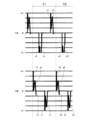
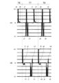
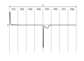
- 16 to 18 show examples of waveforms of voltage VA and voltage VB measured in the initialization operation. Pulses P[1] to P[8] are input to stepping motor 66 in ascending order during periods T1 to T9, respectively. Although not shown in FIG. 16, the waveform of voltage VA and the waveform of voltage VB before period T1 are the same (including substantially the same) as the waveform of voltage VA and the waveform of voltage VB in period T1. . In the electric valve device 1, for example, the pulse P has a period of 8 ms and one period T is 64 ms. At time tc, the valve body 30 contacts the valve seat 18 and the rotor 41 is positioned at the valve closing position Rc.
- the movable stopper 42s contacts the fixed stopper 44s, and the rotor 41 is positioned at the reference position Rx. Rotation of the rotor 41 in the first direction is allowed before time tx and restricted after time tx.
- the waveforms of voltage VA are A wave (a1 to a9), B wave (b1 to b9), C wave (c1 to c9), D wave (d1 to d9), and E wave (e7 to e9). ,including.
- the A and B waves are negative voltage (-V) waves observed periodically over all periods T.
- the C and D waves are positive voltage (+V) waves observed periodically over all periods T.
- the E wave is a positive voltage (+V) wave periodically observed after time tx. Each wave has an amplitude equal to or greater than a predetermined magnitude.
- SA1 to SA9 be the areas of the waveform (waveform including C wave and D wave) in the section corresponding to pulse P[7] in periods T1 to T9, and areas SA6 to SA9 in periods T6 to T9 after time tx are It is smaller than the areas SA1-SA5 in the period T1-T5 before the time tx.
- the D wave is a positive voltage wave with relatively large amplitude before time tx (d1 to d5), and becomes a positive voltage wave with relatively small amplitude after time tx (d6 to d9).
- the E wave is not observed before time tx, but is periodically observed after time tx (e7 to e9). That is, the E wave is a new wave that is different from the waves that are periodically observed over the entire period T, and periodically appears after time tx.
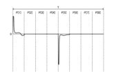
- the waveform of the voltage VB is F wave (f1 to f9), G wave (g1 to g9), H wave (h1 to h9), J wave (j1 to j9), and K wave (k1 to k9).
- M-waves (m7-m9).
- the F and G waves are positive voltage (+V) waves observed periodically over all periods T.
- the H-, J- and K-waves are negative voltage (-V) waves observed periodically over all periods T.
- the M-wave is a positive voltage (+V) wave periodically observed after time tx. Each wave has an amplitude equal to or greater than a predetermined magnitude.
- SB1 to SB9 be the areas of the waveform (waveform including F wave, G wave and H wave) in the interval corresponding to pulse P[1] in period T1 to T9, then area SB7 to SB9 is smaller than areas SB1 to SB6 in periods T1 to T6 before time tx.
- the G wave is a positive voltage wave with relatively large amplitude before time tx (g1 to g6), and becomes a negative voltage wave with relatively small amplitude after time tx (g7 to g9).
- the G wave is combined with the H wave after time tx to form one wave (g7 to g9).
- the K wave is a negative voltage wave with relatively small amplitude before time tx (k1 to k5), and becomes a negative voltage wave with relatively large amplitude after time tx (k7 to k9).
- the M wave is not observed before time tx, but is periodically observed after time tx (m7 to m9). That is, the M wave is a new wave different from the waves periodically observed over the entire period T, and periodically appears after the time tx.
- the waveform of the voltage VA and the waveform of the voltage VB have the following differences before and after the time tx.
- the area of the waveform in the period T after the time tx is smaller than the area of the waveform in the period T before the time tx.
- the amplitude of the wave after time tx is different from the amplitude of the wave before time tx;
- state determination unit 83 detects none of the phenomena (i) to (iii) above in the waveform of voltage VA and the waveform of voltage VB acquired by voltage acquisition unit 82 during the initialization operation. , that the motor-operated valve 5 is in the rotation permitting state Sp.
- the state determination unit 83 determines that the motor operated valve 5 is in the rotation restriction state Sr when at least one of the phenomena (i) to (iii) is detected. Then, when the state determination unit 83 determines that the rotation restriction state Sr is reached, the rotation control unit 81 stops inputting the pulses P[1] to P[8] to the stepping motor 66, and ends the initialization operation. do.
- the state determination unit 83 may determine that the motor operated valve 5 is in the rotation restricted state Sr when two or more of the phenomena shown in (i) to (iii) above are detected. In this case, when the state determination unit 83 does not determine that the motor-operated valve 5 is in the rotation restricting state Sr, it determines that the motor-operated valve 5 is in the rotation permitting state Sp.
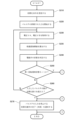
- the electric valve control device 70 (specifically, the computer 80) receives an initialization command from the air conditioner control device 110 (S110), the pulses P[1] to P[8] are input to the stepping motor 66 in ascending order. is started (S120). As a result, the initialization operation is started, the drive current corresponding to the pulses P[1] to P[8] is supplied to the stator 60, and the rotor 41 rotates in the first direction.
- the electric valve control device 70 controls the voltage VA generated between the terminals A1 and A2 of the coil 61c of the A-phase stator 61 and the terminals B1 and B2 of the coil 62c of the B-phase stator 62.
- a voltage VB generated in between is obtained in time series (S130). That is, the electric valve control device 70 acquires the waveform of the voltage VA and the waveform of the voltage VB.
- the motor-operated valve control device 70 determines the state of the motor-operated valve 5 at the timing when the current period T in which the pulses P[1] to P[8] are input ends (S140). Specifically, the electric valve control device 70 performs the following (1) to (8).
- the electric valve control device 70 calculates the area SA(k) of the waveform of the section corresponding to the pulse P[7] in the current period T(k) with respect to the waveform of the voltage VA. Then, the motor-operated valve control device 70 determines that the area SA(k) is larger than the area SA(k-1) of the waveform in the section corresponding to the pulse P[7] in the period T(k-1) one before. When it is detected that the difference between the areas SA(k) and SA(k-1) is small and equal to or greater than a predetermined first area determination value, it is determined that the motor operated valve 5 is in the rotation restricted state Sr. Note that the area SA(k) may be the area of the waveform in a partial section of the period T(k) or the area of the waveform in the entire section of the period T(k).
- the electric valve control device 70 acquires the amplitude WA(k) of the D wave in the current period T(k) with respect to the waveform of the voltage VA. Then, the electric valve control device 70 determines that the amplitude WA(k) is smaller than the amplitude WA(k ⁇ 1) of the D wave in the immediately preceding period T(k ⁇ 1) and the amplitude WA(k) and the amplitude WA( k ⁇ 1) is equal to or greater than a predetermined first amplitude determination value, it is determined that the motor operated valve 5 is in the rotation restricted state Sr.
- the motor-operated valve control device 70 has a plurality of periods T (for example, three periods), it is determined that the motor-operated valve 5 is in the rotation restricted state Sr.
- the electric valve control device 70 calculates the area SB(k) of the waveform of the section corresponding to the pulse P[1] in the current period T(k) with respect to the waveform of the voltage VB. Then, the electric valve control device 70 determines that the area SB(k) is larger than the area SB(k ⁇ 1) of the waveform in the section corresponding to the pulse P[1] in the period T(k ⁇ 1) one before. When it is detected that the difference between the area SB(k) and the area SB(k-1) is small and equal to or greater than a predetermined second area determination value, it is determined that the motor operated valve 5 is in the rotation restricted state Sr. Note that the area SB(k) may be the area of the waveform in a partial section of the period T(k) or the area of the waveform in the entire section of the period T(k).
- the electric valve control device 70 acquires the amplitude WB1(k) of the G wave in the current period T(k) with respect to the waveform of the voltage VB. Then, the electric valve control device 70 determines that the amplitude WB1(k) is smaller than the amplitude WB1(k-1) of the G wave in the immediately preceding period T(k-1) and that the amplitude WB1(k) and the amplitude WB1( k ⁇ 1) is equal to or greater than a predetermined second amplitude determination value, it is determined that the motor operated valve 5 is in the rotation restricted state Sr.
- the electric valve control device 70 obtains the amplitude WB2(k) of the K wave in the current period T(k) with respect to the waveform of the voltage VB. Then, the electric valve control device 70 determines that the amplitude WB2(k) is larger than the amplitude WB2(k ⁇ 1) of the K wave in the immediately preceding period T(k ⁇ 1) and that the amplitude WB2(k) and the amplitude WB2( k ⁇ 1) is equal to or greater than a predetermined third amplitude determination value, it is determined that the motor operated valve 5 is in the rotation restricted state Sr.
- the motor-operated valve control device 70 has a plurality of consecutive periods of new M waves that are different from the F, G, H, J, and K waves observed over the entire period T. When it is detected that it appears periodically over T (for example, three periods), it is determined that the motor operated valve 5 is in the rotation restricted state Sr.
- the areas and amplitudes used in (1), (2), (4) to (6) above may be moving average values in a plurality of consecutive periods T. Further, the electric valve control device 70 may perform only part of the above (1) to (7).
- the motor-operated valve control device 70 determines that the motor-operated valve 5 is in the rotation permitting state Sp when it is not determined that the motor-operated valve 5 is in the rotation restricting state Sr in (1) to (7) above. .
- the electric valve control device 70 may make the above (1) to (7) provisional determinations.
- the motor-operated valve control device 70 formally determines that the motor-operated valve 5 is in the rotation restricted state Sr when it has provisionally determined that the motor-operated valve 5 is in the rotation restricted state Sr a plurality of times (for example, two or more times).
- the motor-operated valve control device 70 determines that the motor-operated valve 5 is in the rotation-permitting state Sp when it does not formally determine that the motor-operated valve 5 is in the rotation-restricting state Sr.
- the motor-operated valve control device 70 terminates the input of the pulses P[1] to P[8] to the stepping motor 66, and the air conditioner control device 110 The completion of the initialization operation is notified (S170).
- the motor-operated valve control device 70 When the motor-operated valve 5 is in the rotation permitting state Sp (N in S150) and the number of pulses P input to the stepping motor 66 exceeds the initialization number X (Y in S160), the motor-operated valve control device 70 The input of the pulse P to 66 is ended, and the completion of the initialization operation is notified to the air conditioner control device 110 (S170).
- the initialization number X is the number of pulses P required to rotate the rotor 41 from the position (fully open position Rz) of the rotor 41 corresponding to the maximum opening of the valve port 17 to the reference position Rx. For example, the initialization number X is 500.
- the electric valve control device 70 acquires the voltage VA and the voltage VB again (S130), and performs the above operation (S130 to S160) are repeated.
- the motor-operated valve device 1 has a motor-operated valve 5 and a motor-operated valve control device 70 .
- the motor-operated valve 5 includes a valve body 10 having a valve seat 18, a rotor 41 rotatable with respect to the valve body 10, a stator 60 forming a stepping motor 66 together with the rotor 41, and the valve seat 18 facing each other.
- a valve body 30 that is pushed toward the valve seat 18 via a valve closing spring 47 when it rotates in the first direction, and a stopper mechanism that restricts rotation of the rotor 41 in the first direction when the rotor 41 is at the reference position Rx. 49 and .
- the electric valve control device 70 supplies drive current to the stator 60 to rotate the rotor 41 in the first direction.
- Electric valve control device 70 acquires voltage VA and voltage VB generated in stator 60 by rotation of rotor 41 . Then, the motor-operated valve control device 70 determines (i) the areas of the waveforms of the voltages VA and VB, (ii) the amplitude of the waves periodically observed in the waveforms of the voltages VA and VB, and (iii) the voltages VA and the periodic appearance of a new wave different from the periodically observed wave in the waveform of the voltage VB, the motor-operated valve 5 is caused to move the rotor 41 in the first direction by the stopper mechanism 49. It is determined whether or not it is in the rotation restriction state Sr in which rotation is restricted.
- the motor-operated valve control device 70 determines that the motor-operated valve 5 is in the rotation restricted state Sr, the rotor 41 is at the reference position Rx. Therefore, by stopping the rotation of the rotor 41 in the first direction when the motor-operated valve control device 70 determines that the motor-operated valve 5 is in the rotation restricted state Sr, the time required for the initialization operation can be shortened. can. In addition, the number of times the movable stopper 42s repeatedly collides with the fixed stopper 44s after the rotor 41 is positioned at the reference position Rx can be reduced.
- the electric valve control device 70 can prevent noise from being generated for a long period of time, and can also prevent wear and fatigue of the movable stopper 42s and the fixed stopper 44s.
- the motor-operated valve control device 70 can suppress noise and extend the life of the motor-operated valve 5 .
- the motor-operated valve control device 70 determines whether or not the motor-operated valve 5 is in the rotation restricted state Sr based on the area SA of the waveform of the voltage VA and the area SB of the waveform of the voltage VB.
- the electric valve control device 70 controls the amplitude WA of the D wave periodically observed in the waveform of the voltage VA, and the amplitude WB1 of the G wave and the amplitude WB2 of the K wave periodically observed in the waveform of the voltage VB. Based on this, it is determined whether or not the motor-operated valve 5 is in the rotation restricted state Sr.
- the motor-operated valve control device 70 controls the periodic appearance of a new E wave that is different from the A wave, B wave, C wave, and D wave that are periodically observed in the waveform of the voltage VA, and the periodic appearance of the E wave in the waveform of the voltage VB. Whether or not the electric valve 5 is in the rotation restriction state Sr is determined based on the periodic appearance of a new M wave different from the F, G, H, J, and K waves that are typically observed. judge. By doing so, it is possible to determine whether or not the motor-operated valve 5 is in the rotation restricted state Sr by performing relatively simple processing on the voltages VA and VB.
- the motor-operated valve control device 70 determines that the motor-operated valve 5 is in the rotation restricted state Sr, it stops inputting the pulse P to the stepping motor 66 and stops supplying the drive current to the stator 60 .
- the motor-operated valve control device 70 determines that the motor-operated valve 5 is in the rotation restricted state Sr, it stops inputting the pulse P to the stepping motor 66 and stops supplying the drive current to the stator 60 .
- the stator 60 has an A-phase stator 61 and a B-phase stator 62 .
- the motor-operated valve control device 70 obtains the voltage VB generated in the B-phase stator 62 when the drive current is supplied only to the A-phase stator 61, and the voltage VB to the A-phase stator 61 when the drive current is supplied only to the B-phase stator 62. Obtain the resulting voltage VA.
- the electric valve control device 70 there is no need to separate the voltage component related to electromagnetic induction from the voltage generated in the A-phase stator 61, and the voltage component related to electromagnetic induction can be separated from the voltage generated in the B-phase stator 62. No need to separate. Therefore, voltage VA and voltage VB can be obtained with a relatively simple configuration.
- the motor-operated valve control device 70 determines whether the motor-operated valve 5 is in the rotation permitting state Sp or the rotation restricting state Sr.
- the motor-operated valve control device 70 may determine a state of the motor-operated valve 5 other than the rotation permitting state Sp or the rotation restricting state Sr.
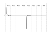
- the D wave is a positive voltage wave (d1, d2) with a constant amplitude in each period T before time tc, and between time tc and time tx The amplitude gradually decreases (d3-d5).
- the K wave is a negative voltage wave (k1, k2) whose amplitude is constant in each period before the time tc, and the amplitude gradually decreases from the time tc to the time tx. (d3-d5).
- the motor-operated valve control device 70 when the amplitude of the D wave periodically observed in the waveform of the voltage VA gradually decreases, and/or when the amplitude of the K wave periodically observed in the waveform of the voltage VB gradually decreases, the motor-operated valve control device 70 Then, it may be determined that the motor operated valve 5 is in the intermediate state Sq in which the rotor 41 is between the closed position Rc and the reference position Rx.
- the intermediate state Sq is a state between the rotation permitted state Sp and the rotation restricted state Sr. For example, by including determination that the motor operated valve 5 is in the intermediate state Sq in the determination condition of the rotation restricted state Sr, the accuracy of determination of the rotation restricted state Sr can be further improved.
- the motor-operated valve 5 is configured such that when the rotor 41 rotates in the first direction, the valve shaft holder 42 fitted with the rotor 41 pushes the valve body 30 downward via the valve closing spring 47 .
- the motor-operated valve 5 may be configured such that when the rotor 41 rotates in the first direction, the valve shaft holder 42 fitted with the rotor 41 directly pushes the valve body 30 downward.
- the motor-operated valve 5 may have a configuration in which the rotor 41 (or the valve shaft holder 42) and the valve body 30 are fixed. In this configuration, when the valve body 30 comes into contact with the valve seat 18, the rotation of the rotor 41 in the first direction is restricted. That is, the valve body 30 and the valve seat 18 constitute a stopper mechanism, and the position of the rotor 41 when the valve body 30 contacts the valve seat 18 is the reference position where the rotation of the rotor 41 in the first direction is restricted. Rx.
- the motor-operated valve control device 70 also determines whether the motor-operated valve 5 is in the rotation restricted state Sr based on the voltage generated in the stator 60 by the rotation of the rotor 41 . Since current and voltage are closely related, the motor-operated valve control device 70 determines whether or not the motor-operated valve 5 is in the rotation restricted state Sr based on the current generated in the stator 60 by the rotation of the rotor 41. may In this configuration, the electric valve control device 70 has a current acquisition section that acquires the current generated in the stator 60 due to the rotation of the rotor 41 (current electromagnetically induced in the stator 60) instead of the voltage acquisition section.
- the state determination unit determines (i) the area of the current waveform, (ii) the amplitude of the waves periodically observed in the current waveform, and (iii) the waves periodically observed in the current waveform. and periodic appearance of a different new wave.
- the electric valve 5 has a drive mechanism 40 that uses the rotation of the rotor 41 without decelerating it. Instead of the drive mechanism 40, the electric valve 5 may have a drive mechanism having a deceleration mechanism for reducing the rotation speed of the rotor 41.
- the motor-operated valve device 2 has the same hardware configuration as the motor-operated valve device 1 .
- the operation of the motor-operated valve control device 70 of the motor-operated valve device 2 differs from the operation of the motor-operated valve control device 70 of the motor-operated valve device 1 .
- the electric valve control device 70 acquires the voltage VA and the voltage VB in time series. That is, the electric valve control device 70 acquires the waveform of the voltage VA and the waveform of the voltage VB. Then, the motor-operated valve control device 70 determines the state of the motor-operated valve 5 by comparing the waveform of the voltage VA and the waveform of the voltage VB with preset reference waveforms of the voltage VA and VB.
- the motor-operated valve 5 has a first rotation permitting state Sp1, a second rotation permitting state Sp2, a first rotation restricting state Sr1, and a second rotation restricting state Sr2.
- the first rotation permission state Sp1 is a state in which rotation of the rotor 41 in the first direction is permitted.
- the second rotation permission state Sp2 is a state in which rotation of the rotor 41 in the second direction is permitted.
- the first rotation restricted state Sr1 is a state in which rotation of the rotor 41 in the first direction is restricted.
- the second rotation restricted state Sr2 is a state in which rotation of the rotor 41 in the second direction is restricted.
- the nonvolatile memory 75 of the electric valve control device 70 stores the reference waveform of the voltage VA and the reference waveform of the voltage VB.
- the reference waveform includes a first rotation-allowed state waveform, a second rotation-allowed state waveform, and a first rotation-restricted state waveform.
- a reference waveform is set for the pulse P.
- the reference waveform is set for a portion of the pulse P (P[1], P[3], P[5], P[7]) and the remaining pulse P (P[ 2], P[4], P[6], P[8]) are not set.
- the reference waveform is set based on the waveform of the voltage VA and the waveform of the voltage VB obtained at the electrically operated valve 5 capable of normal operation.
- the first rotation permissible state waveform of the voltage VA is that the motor-operated valve 5 is in the first rotation permissible state Sp1 and the B-phase stator 62 is rotated in response to the pulses P[3] and P[7] that rotate the rotor 41 in the first direction. It is set based on the waveform of the voltage VA obtained when the drive current is supplied only to the coil 62c.
- the first rotation permissible state waveform of the voltage VB is that the motor-operated valve 5 is in the first rotation permissible state Sp1 and the A-phase stator 61 is rotated in response to the pulses P[1] and P[5] that rotate the rotor 41 in the first direction. It is set based on the waveform of the voltage VB obtained when the drive current is supplied only to the coil 61c.
- the second rotation permissible state waveform of the voltage VA is that the motor-operated valve 5 is in the second rotation permissible state Sp2 and the B-phase stator 62 is rotated in response to the pulses P[3] and P[7] that rotate the rotor 41 in the second direction. It is set based on the waveform of the voltage VA obtained when the drive current is supplied only to the coil 62c.
- the second rotation permissible state waveform of the voltage VB is that the motor-operated valve 5 is in the second rotation permissible state Sp2 and the A-phase stator 61 is rotated in response to the pulses P[1] and P[5] that rotate the rotor 41 in the second direction. It is set based on the waveform of the voltage VB obtained when the drive current is supplied only to the coil 61c.
- the first rotation permissible state waveform and the second rotation permissible state waveform are a plurality of voltage waveforms (waveform of voltage VA and waveform of voltage VB) obtained individually for each motor-operated valve 5 at the time of shipment from the factory. set based on The motor-operated valve control device 70 stores a first rotation permissible state waveform and a second rotation permissible state waveform set based on a plurality of voltage waveforms acquired in the motor-operated valve 5 combined therewith.
- first rotation permissible state waveform and the second rotation permissible state waveform may be set based on a plurality of voltage waveforms acquired in the plurality of motor operated valves 5 .
- a common first rotation permissible state waveform and a second rotation permissible state waveform are stored in the plurality of electric valve control devices 70 .
- the first rotation permissive state waveform is the centerline of the plurality of voltage waveforms.
- the second rotation permissive state waveform is the center line of the plurality of voltage waveforms.
- the center line is, for example, a line connecting the average voltages at each acquisition time (sampling time) in the waveforms of a plurality of voltages in order of the acquisition time.
- the first rotation permissible state waveform of voltage VA is set for pulses P[3] and P[7] one each, and the first rotation permissible state waveform of voltage VB is set for pulses P[1] and P[5]. are set one by one.
- the second rotation permissible state waveform of voltage VA is set for pulses P[3] and P[7] one each, and the second rotation permissible state waveform of voltage VB is set for pulses P[1] and P[5]. are set one by one.
- FIG. 20 shows an example of waveforms including the first rotation permissible state waveform of voltage VB set for pulse P[1] and the first rotation permissible state waveform of voltage VB set for pulse P[5]. indicates
- the first rotation permissible state waveform and the second rotation permissible state waveform are stored in the nonvolatile memory 75 as a data table.
- the nonvolatile memory 75 stores first rotation permission state tables C[3], C[7], C[1] and C[5].
- the first rotation permissible state table C[3] is the first rotation permissible state waveform of the voltage VA set for the pulse P[3] input when rotating the rotor 41 in the first direction.
- the first rotation permissible state table C[7] is the first rotation permissible state waveform of the voltage VA set for the pulse P[7] input when rotating the rotor 41 in the first direction.
- the first rotation permissible state table C[1] is the first rotation permissible state waveform of the voltage VB set for the pulse P[1] input when rotating the rotor 41 in the first direction.
- the first rotation permissible state table C[5] is the first rotation permissible state waveform of the voltage VB set for the pulse P[5] input when rotating the rotor 41 in the first direction.
- Pulses P[3], P[7], P[1] and P[5] input when rotating the rotor 41 in the first direction are first direction pulses.
- the nonvolatile memory 75 stores second rotation permission state tables D[3], D[7], D[1] and D[5].
- the second rotation permissible state table D[3] is the second rotation permissible state waveform of the voltage VA set for the pulse P[3] input when rotating the rotor 41 in the second direction.
- the second rotation permissible state table D[7] is the second rotation permissible state waveform of the voltage VA set for the pulse P[7] input when rotating the rotor 41 in the second direction.
- the second rotation permissible state table D[1] is the second rotation permissible state waveform of the voltage VB set for the pulse P[1] input when rotating the rotor 41 in the second direction.
- the second rotation permissible state table D[5] is the second rotation permissible state waveform of the voltage VB set for the pulse P[5] input when rotating the rotor 41 in the second direction.
- Pulses P[3], P[7], P[1] and P[5] input when rotating the rotor 41 in the second direction are second direction pulses.
- the first rotation restriction state waveform of the voltage VA is that the motor-operated valve 5 is in the first rotation restriction state Sr1 and the B-phase stator 62 is rotated in response to the pulses P[3] and P[7] that rotate the rotor 41 in the first direction. It is set based on the waveform of the voltage VA obtained when the drive current is supplied only to the coil 62c.
- the first rotation restriction state waveform of the voltage VB is that the motor-operated valve 5 is in the first rotation restriction state Sr1 and the A-phase stator 61 is rotated in response to the pulses P[1] and P[5] that rotate the rotor 41 in the first direction. It is set based on the waveform of the voltage VB obtained when the drive current is supplied only to the coil 61c.
- the pulse P (pattern number) corresponding to the timing at which the rotation of the rotor 41 in the first direction is restricted by the stopper mechanism 49 differs depending on the accuracy of parts and assembly accuracy.
- the timing at which the rotation of the rotor 41 in the first direction is restricted by the stopper mechanism 49 is the timing at which the movable stopper 42s contacts the fixed stopper 44s.
- the movable stopper 42s contacts the fixed stopper 44s at the timing when the pulse P[1] is input, and the pulse P[1] 2] (or any of P[3] to P[8]) is input, the movable stopper 42s contacts the fixed stopper 44s (the latter electric valve 5).
- the former motor-operated valve 5 and the latter motor-operated valve 5 differ in the position of the rotor 41 (specifically, the relative position between the rotor 41 and the stator 60) at the timing when each pulse P is input.
- the motor-operated valve 5 and the latter motor-operated valve 5 differ in the position of the rotor 41 at the timing when the pulse P[1] (or any of P[2] to P[8]) is input, for example. If the position of the rotor 41 in the electric valve 5 is different, the waveform of the voltage generated by the rotation of the rotor 41 is also different. Therefore, the former motor-operated valve 5 and the latter motor-operated valve 5 have different voltage waveforms (the waveform of the voltage VA and the waveform of the voltage VB) when the pulse P having the same pattern number is input.
- the plurality of electric valves 5 having different pulses P corresponding to the timing at which the movable stopper 42s contacts the fixed stopper 44s have different voltage waveforms when one pulse P having the same pattern number is input.
- the number of variation waveforms of the first rotation restriction state waveform of voltage VA for one pulse P is the same as the number of pulse P patterns.
- the number of variation waveforms of the first rotation restriction state waveform of voltage VB for one pulse P is also the same as the number of pulse P patterns.
- the pulse P (pattern number) corresponding to the timing at which the movable stopper 42s contacts the fixed stopper 44s is always the same.
- the pulse P input at the timing when the movable stopper 42s comes into contact with the fixed stopper 44s is the pulse P[1].
- the pulse P input at the timing when the movable stopper 42s contacts the fixed stopper 44s is the pulse P[2] (or any of [3] to [8]).
- the first rotation restriction state waveform is set based on a plurality of voltage waveforms (waveform of voltage VA and waveform of voltage VB) individually obtained in each motor-operated valve 5 at the time of shipment from the factory.
- the motor-operated valve control device 70 stores a first rotation restriction state waveform set based on a plurality of voltage waveforms acquired in the motor-operated valve 5 combined therewith.
- the first rotation restriction state waveform of voltage VA is set for each of pulses P[3] and P[7]
- the first rotation restriction state waveform of voltage VB is set for pulses P[1] and P[7].
- One is set for P[5].
- the first rotation restriction state waveform may be set based on a plurality of voltage waveforms acquired in the plurality of motor operated valves 5 .
- a common first rotation restriction state waveform is stored in the plurality of electric valve control devices 70 .
- a plurality of first rotation restriction state waveforms are set for pulses P[3], P[7], P[1] and P[5].
- the plurality of first rotation restriction state waveforms are composed of variation waveforms of the first rotation restriction state waveform.
- Eight first rotation restriction state waveforms of voltage VA are set for pulses P[3] and P[7]
- the first rotation restriction state waveform of voltage VB is set for pulses P[1] and P[5]. 8 are set for each.
- the one most suitable for the motor-operated valve 5 combined with the motor-operated valve control device 70 is set as the first rotation restriction state waveform in the motor-operated valve control device 70.
- the first rotation restriction state waveform of voltage VA is set for each of pulses P[3] and P[7]
- the first rotation restriction state waveform of voltage VB is set for pulses P[1] and P[ 5] is set one by one.
- the motor-operated valve 5 is in a state in which rotation of the rotor 41 in the first direction is restricted by the stopper mechanism 49 .
- the first rotation restriction state waveform is the center line of the plurality of voltage waveforms.
- the first rotation restriction state waveform is stored in the nonvolatile memory 75 as a data table.
- the nonvolatile memory 75 stores first rotation regulation state tables E[3], E[7], E[1] and E[5].
- the first rotation restriction state table E[3] is the first rotation restriction state waveform of the voltage VA set for the pulse P[3] input when rotating the rotor 41 in the first direction.
- the first rotation restriction state table E[7] is the first rotation restriction state waveform of the voltage VA set for the pulse P[7] input when rotating the rotor 41 in the first direction.
- the first rotation restriction state table E[1] is the first rotation restriction state waveform of the voltage VB set for the pulse P[1] input when rotating the rotor 41 in the first direction.
- the first rotation restriction state table E[5] is the first rotation restriction state waveform of the voltage VB set for the pulse P[5] input when rotating the rotor 41 in the first direction.
- non-volatile memory 75 stores first rotation restriction waveforms.
- State tables E[3]_1 to E[3]_8, E[7]_1 to E[7]_8, E[1]_1 to E[1]_8 and E[5]_1 to E[5]_8 are remembered.
- the first rotation regulation state tables E[3]_1 to E[3]_8 are the eight voltages VA set for the pulse P[3] input when rotating the rotor 41 in the first direction. It is a one-rotation regulation state waveform.
- the first rotation regulation state tables E[7]_1 to E[7]_8 are the eight voltages VA set for the pulse P[7] input when rotating the rotor 41 in the first direction. It is a one-rotation regulation state waveform.
- the first rotation regulation state tables E[1]_1 to E[1]_8 are the eight voltages VB set for the pulse P[1] input when rotating the rotor 41 in the first direction. It is a one-rotation regulation state waveform.
- the first rotation regulation state tables E[5]_1 to E[5]_8 are the eight voltages VB set for the pulse P[5] input when rotating the rotor 41 in the first direction. It is a one-rotation regulation state waveform.
- the waveforms shown in FIGS. 21 to 28 are obtained by the motor operated valve 5 having different pulses P corresponding to the timing at which the movable stopper 42s comes into contact with the fixed stopper 44s. It is an example of a variation waveform.
- a data table stored in the nonvolatile memory 75 in this embodiment is shown below.
- the numbers in square brackets correspond to the pulse P pattern numbers.
- each data table the time t at predetermined intervals from the start of the pulse P (time 0) and the reference voltage rv at the time t are associated.
- the period from the beginning to the end of the pulse P is 8 ms
- the time interval t is 200 ⁇ s.
- One data table has 40 sets of time t and reference voltage rv.
- FIG. 29 shows an example of the first rotation permission state table C[1].
- the unit of time t is ⁇ s.
- the unit of the reference voltage rv is mv.
- the unit of the time t and the unit of the reference voltage rv may be unique units such as those corresponding to the sampling period and resolution of the A/D converter of the motor-operated valve control device 70, for example.
- the computer 80 of the electric valve control device 70 functions as a rotation control section 81, a voltage acquisition section 82, and a state determination section 83.
- the rotation control unit 81 and the voltage acquisition unit 82 have the same (including substantially the same) functions as those of the electric valve device 1 described above.
- the voltage acquisition unit 82 acquires the voltage VA and the voltage VB in time series at the same time interval as the time t in the data table during the period from the start to the end of the pulse P.
- FIG. In this embodiment, the voltage acquisition unit 82 acquires the voltage VA and the voltage VB 40 times in response to the input of one pulse P.
- state determination unit 83 converts the voltage waveforms (waveform of voltage VA and waveform of voltage VB) acquired by voltage acquisition unit 82 into reference waveforms of voltage (reference waveform of voltage VA and reference waveform of voltage VB). ) is calculated (dissimilarity index value).
- the state determination unit 83 determines the state of the motor operated valve 5 based on the difference index value. The greater the difference index value, the greater the degree of difference between the voltage waveform and the voltage reference waveform.
- the state determination unit 83 Data table of reference waveform corresponding to pulse P (at least one of first rotation permissible state table C[k], second rotation permissible state table D[k], and first rotation restriction state table E[k]) to read the reference voltage rv associated with the time t corresponding to the acquisition time tv.
- the state determination unit 83 calculates a value (difference value dv) by subtracting the reference voltage rv from the voltage v acquired by the voltage acquisition unit 82 .
- the state determination unit 83 calculates a value (intermediate value dv2) obtained by squaring the difference value dv.
- the state determination unit 83 sums up a plurality of intermediate values dv2 calculated corresponding to the input of the pulse P[k] to calculate the dissimilarity index value sv[k].
- the state determination unit 83 compares the dissimilarity index value sv[k] with a predetermined dissimilarity determination value H. FIG. Based on the result of comparison between the difference index value sv[k] and the difference determination value H, the state determination unit 83 determines whether the motor-operated valve 5 is in the first rotation allowable state Sp1, the second rotation allowable state Sp2, or the first rotation restriction state.
- the state determination unit 83 determines that the motor-operated valve 5 rotates in the first direction when the pulses P[2], P[4], P[6], and P[8] that rotate the rotor 41 in the first direction are input. It is determined to be the allowable state Sp1. When the pulses P[2], P[4], P[6], and P[8] for rotating the rotor 41 in the second direction are input, the state determination unit 83 determines that the motor-operated valve 5 is in the second rotation permissible state. It is determined to be Sp2.
- the state determination unit 83 calculates the difference index value sv[k] using the voltage v acquired by the voltage acquisition unit 82 during a part of the period from the beginning to the end of the pulse P[k]. do. Specifically, when the first period p1 is from the start of the pulse P[k] to time t1, and the second period p2 is from time t1 to time t2, the state determination unit 83 detects the voltage of the second period p2. A dissimilarity index value sv[k] is calculated using v.
- FIG. 30 shows an example of the waveform of the voltage VB (solid line) and the waveform of the first rotation permissible state of the voltage VB (broken line) obtained in response to the input of the pulse P[1].
- Time t1 is a time after the beginning of pulse P[k].
- Time t2 is a time after time t1 and before the end of pulse P[k].
- Time t2 may be the end of pulse P[k].
- the length of the vertical line connecting the waveform of the voltage VB and the first rotation permissible state waveform of the voltage VB in the second period p2 is the difference value dv used to calculate the difference index value svC[1]. handle.
- the state determination unit 83 does not use the voltage v of the first period p1 to calculate the dissimilarity index value sv[k].
- the voltage v is a voltage component related to the back electromotive force due to the inductance of the coil of the stator 60 (the former voltage component) and a voltage related to electromagnetic induction due to the rotation of the rotor 41. component (the latter voltage component), and the former voltage component is greater than the latter voltage component.
- the former voltage component becomes smaller over time. Therefore, the state determination unit 83 calculates the dissimilarity index value sv[k] using the voltage v acquired by the voltage acquisition unit 82 after a certain amount of time has passed since the start of the pulse P[k].
- the state determination unit 83 calculates the dissimilarity index value sv[k] using the voltage v acquired by the voltage acquisition unit 82 after the former voltage component becomes smaller than the latter voltage component. By doing so, the ratio of the latter voltage component in the voltage v becomes relatively large, and the state determination unit 83 can determine the state of the motor-operated valve 5 with higher accuracy.
- the length of the first period p1 is 5-50%, preferably 20-30%, of the period from the beginning to the end of the pulse P[k].
- the length of the second period p2 is 50-95%, preferably 70-80%, of the period from the beginning to the end of the pulse P[k].
- the voltage component related to the back electromotive force due to the coil inductance of the stator 60 is smaller than the voltage component related to electromagnetic induction due to the rotation of the rotor 41 .
- the state determination unit 83 uses the voltage v acquired by the voltage acquisition unit 82 during the period from the beginning to the end of the pulse P[k] (the entire period) to calculate the dissimilarity index value sv[k]. good too. In this case, the beginning of pulse P[k] is time t1, and the end of pulse P[k] is time t2.
- v[tv] be the voltage v acquired at the acquisition time tv between time t1 and time t2
- rv[tv] be the reference voltage rv associated with the time t corresponding to the acquisition time tv in the reference waveform data table.
- the dissimilarity index value sv is given by the following equation (1).
- the motor-operated valve control device 70 ends the initialization operation of the motor-operated valve 5 when the rotation of the rotor 41 in the first direction is restricted.
- the electric valve control device 70 When the electric valve control device 70 receives an initialization command from the air conditioner control device 110 (S210), it starts inputting pulses P[1] to P[8] in ascending order to the stepping motor 66 (S220). As a result, the initialization operation is started, the drive current corresponding to the pulses P[1] to P[8] is supplied to the stator 60, and the rotor 41 rotates in the first direction.
- the electric valve control device 70 controls the voltage VA generated between the terminals A1 and A2 of the coil 61c of the A-phase stator 61 and the terminals B1 and B2 of the coil 62c of the B-phase stator 62.
- a voltage VB generated in between is obtained in time series (S230). That is, the electric valve control device 70 acquires the waveform of the voltage VA and the waveform of the voltage VB.
- the motor-operated valve control device 70 calculates the difference index value sv (S235), and determines the state of the motor-operated valve 5 based on the difference index value sv (S240). There are three methods for determining the first rotation restriction state Sr1 based on the difference index value sv. Determination method 1: Only the first rotation permission state table C is used. Judgment method 2: Only the first rotation regulation state table E is used. Determination method 3: The first rotation permission state table C and the first rotation restriction state table E are used.
- the motor-operated valve control device 70 may determine the state of the motor-operated valve 5 using only one of the waveform of the voltage VA and the waveform of the voltage VB. Motor-operated valve control device 70 may determine the state of motor-operated valve 5 using only the waveform of voltage VA corresponding to one of pulse P[3] and pulse P[7]. Motor-operated valve control device 70 may determine the state of motor-operated valve 5 using only the waveform of voltage VB corresponding to one of pulse P[1] and pulse P[5]. It is preferable that the waveform used for determination has less noise.
- the motor-operated valve control device 70 compares the dissimilarity index value svC[7] with the dissimilarity determination value HC, and calculates immediately before the dissimilarity index value svC[7].
- the dissimilarity index value svC[7]' and the dissimilarity determination value HC are compared. Assuming that the period during which the pulses P[1] to P[8] are input is period T, the difference index value svC[7]' It is calculated accordingly.
- the motor-operated valve control device 70 operates the motor-operated valve 5 to the first position. It is determined that the one-rotation regulation state Sr1 is established. At this time, the electric valve control device 70 stores the number one before k (that is, 8) in the nonvolatile memory 75 as the start pattern number Nx. When the motor-operated valve control device 70 does not determine that the motor-operated valve 5 is in the first rotation restricting state Sr1, it determines that the motor-operated valve 5 is in the first rotation permitting state Sp1.
- the electric valve control device 70 uses the first rotation regulation state table E[k] to calculate the difference index value svE[k] (S235). Specifically, the motor-operated valve control device 70 calculates the difference index value svE[1] using the first rotation regulation state table E[1] in response to the input of the pulse P[1]. The motor-operated valve control device 70 calculates the difference index value svE[3] using the first rotation regulation state table E[3] in response to the input of the pulse P[3]. The electric valve control device 70 calculates the difference index value svE[5] using the first rotation regulation state table E[5] in response to the input of the pulse P[5]. The electric valve control device 70 calculates the difference index value svE[7] using the first rotation regulation state table E[7] in response to the input of the pulse P[7].
- the motor-operated valve control device 70 determines the state of the motor-operated valve 5 at the end of the pulse P[k] (S240). Specifically, the electric valve control device 70 compares the difference index value svE[k] with the difference determination value HE, and calculates the difference index value svE[k] immediately before the difference index value svE[k]. j] and the difference judgment value HE. When the difference index value svE[k] is smaller than the difference judgment value HE and the difference index value svE[j] is smaller than the difference judgment value HE, the electric valve control device 70 controls the first rotation regulation of the electric valve 5. It is determined that the state is Sr1.
- the electric valve control device 70 stores the number immediately before j in the nonvolatile memory 75 as the start pattern number Nx.
- the motor-operated valve control device 70 does not determine that the motor-operated valve 5 is in the first rotation restricting state Sr1, it determines that the motor-operated valve 5 is in the first rotation permitting state Sp1.
- the motor-operated valve control device 70 may determine the state of the motor-operated valve 5 using only the dissimilarity index value svE[k] without using the dissimilarity index value svE[j]. In this case, the motor-operated valve control device 70 determines that the motor-operated valve 5 is in the first rotation restriction state Sr1 when the difference index value svE[k] is smaller than the difference determination value HE. At this time, the electric valve control device 70 stores the number one before k as the start pattern number Nx in the nonvolatile memory 75 . The motor-operated valve control device 70 determines that the motor-operated valve 5 is in the first rotation permissible state Sp1 when the difference index value svE[k] is greater than or equal to the difference determination value HE.
- a plurality of first rotation restriction state waveforms (E[3]_1 to E[3]_8, E[7]_1 to E[7]_8, When E[1]_1 to E[1]_8 and E[5]_1 to E[5]_8) are set, the motor-operated valve control device 70 determines the state of the motor-operated valve 5 as follows. You may The electric valve control device 70 uses the first rotation regulation state tables E[k]_1 to E[k]_8 to calculate the difference index values svE[k]_1 to svE[k]_8.
- the electric valve control device 70 compares each of the difference index values svE[k]_1 to svE[k]_8 with the difference determination value HE, and obtains the difference index values svE[j]_1 to svE[j]_8. are compared with the dissimilarity determination value HE. At least one of the difference index values svE[k]_1 to svE[k]_8 is smaller than the difference determination value HE and the difference index values svE[j]_1 to svE[j]. When at least one of _8 is smaller than the discrepancy determination value HE, it is determined that the motor operated valve 5 is in the first rotation restriction state Sr1.
- the electric valve control device 70 stores the number immediately before j in the nonvolatile memory 75 as the start pattern number Nx.
- the motor-operated valve control device 70 does not determine that the motor-operated valve 5 is in the first rotation restricting state Sr1, it determines that the motor-operated valve 5 is in the first rotation permitting state Sp1.
- the motor-operated valve control device 70 uses only the difference index values svE[k]_1 to svE[k]_8 without using the difference index values svE[j]_1 to svE[j]_8. status may be determined.
- the motor-operated valve control device 70 may determine the state of the motor-operated valve 5 using only one of the waveform of the voltage VA and the waveform of the voltage VB. Motor-operated valve control device 70 may determine the state of motor-operated valve 5 using only the waveform of voltage VA corresponding to one of pulse P[3] and pulse P[7]. Motor-operated valve control device 70 may determine the state of motor-operated valve 5 using only the waveform of voltage VB corresponding to one of pulse P[1] and pulse P[5]. It is preferable that the waveform used for determination has less noise.
- the electric valve control device 70 compares the dissimilarity index value svE[7] with the dissimilarity determination value HE, and calculates immediately before the dissimilarity index value svE[7].
- the dissimilarity index value svE[7]' and the dissimilarity determination value HE are compared.
- the dissimilarity index value svE[7]' is calculated corresponding to the input of the pulse P[7] during the period T immediately preceding the current period T.
- the electric valve control device 70 rotates the electric valve 5 for the first rotation.
- the electric valve control device 70 stores the number one before k (that is, 6) in the nonvolatile memory 75 as the start pattern number Nx.
- the motor-operated valve control device 70 compares the difference index value svE[1] with the difference determination value HE, and calculates the difference index value svE immediately before the difference index value svE[1].
- [1]' is compared with the difference determination value HE.
- the dissimilarity index value svE[1]' is calculated corresponding to the input of the pulse P[1] during the period T immediately preceding the current period T.
- the electric valve control device 70 rotates the electric valve 5 for the first rotation. It is determined that the regulation state is Sr1. At this time, the electric valve control device 70 stores the number one before k (that is, 8) in the nonvolatile memory 75 as the start pattern number Nx. When the motor-operated valve control device 70 does not determine that the motor-operated valve 5 is in the first rotation restricting state Sr1, it determines that the motor-operated valve 5 is in the first rotation permitting state Sp1.
- the electric valve control device 70 uses the first rotation allowable state table C[k] and the first rotation restriction state table E[k] to determine the difference index value svC[k] and the difference index value svE[k]. Calculate (S235). Specifically, the motor-operated valve control device 70 calculates the difference index value svC[1] using the first rotation allowable state table C[1] in response to the input of the pulse P[1]. A discrepancy index value svE[1] is calculated using the one-rotation restriction state table E[1].
- the motor-operated valve control device 70 calculates the difference index value svC[3] using the first rotation allowable state table C[3], and calculates the difference index value svC[3].
- a dissimilarity index value svE[3] is calculated using E[3].
- the motor-operated valve control device 70 calculates the difference index value svC[5] using the first rotation allowable state table C[5], and calculates the difference index value svC[5].
- a dissimilarity index value svE[5] is calculated using E[5].
- the motor-operated valve control device 70 calculates the difference index value svC[7] using the first rotation allowable state table C[7], and calculates the difference index value svC[7].
- a dissimilarity index value svE[7] is calculated using E[7].
- the motor-operated valve control device 70 determines the state of the motor-operated valve 5 at the end of the pulse P[k] (S240). Specifically, the electric valve control device 70 compares the difference index value svC[k] with the difference determination value HC, and calculates the difference index value svC[k] immediately before the difference index value svC[k]. j] and the difference judgment value HC. The electric valve control device 70 compares the difference index value svE[k] with the difference determination value HE, and compares the difference index value svE[j] calculated immediately before the difference index value svE[k] with the difference index value svE[k]. It is compared with the judgment value HE.
- the motor-operated valve control device 70 determines that the dissimilarity index value svC[k] is greater than or equal to the dissimilarity determination value HC, the dissimilarity index value svC[j] is greater than or equal to the dissimilarity determination value HC, and the dissimilarity index value svE[k ] is smaller than the difference determination value HE and the difference index value svE[j] is smaller than the difference determination value HE, it is determined that the motor operated valve 5 is in the first rotation restriction state Sr1. At this time, the electric valve control device 70 stores the number immediately before j in the nonvolatile memory 75 as the start pattern number Nx. When the motor-operated valve control device 70 does not determine that the motor-operated valve 5 is in the first rotation restricting state Sr1, it determines that the motor-operated valve 5 is in the first rotation permitting state Sp1.
- the difference index values svC[k] and svC[j] are the first rotation allowable state difference index values
- the difference index values svE[k] and svE[j] are the first rotation restriction state. It is a dissimilarity index value.
- the difference determination value HC is the first rotation allowable state difference determination value.
- the discrepancy determination value HE is a first rotation restriction state discrepancy determination value.
- the dissimilarity determination value HC may be the same as or different from the dissimilarity determination value HE.
- the motor-operated valve control device 70 determines the difference index value svC[k] and the difference index value svE without using the difference index value svC[j] and the difference index value svE[j].
- the state of the motor operated valve 5 may be determined using only [k]. In this case, when the difference index value svC[k] is greater than or equal to the difference determination value HC and the difference index value svE[k] is smaller than the difference determination value HE, the motor-operated valve control device 70 It is determined that the state is the first rotation restriction state Sr1. At this time, the electric valve control device 70 stores the number one before k as the start pattern number Nx in the nonvolatile memory 75 . The motor-operated valve control device 70 determines that the motor-operated valve 5 is in the first rotation-permitting state Sp1 when it is not determined to be in the first rotation-restricting state Sr1.
- the motor-operated valve control device 70 may determine the state of the motor-operated valve 5 using only one of the waveform of the voltage VA and the waveform of the voltage VB. Motor-operated valve control device 70 may determine the state of motor-operated valve 5 using only the waveform of voltage VA corresponding to one of pulse P[3] and pulse P[7]. Motor-operated valve control device 70 may determine the state of motor-operated valve 5 using only the waveform of voltage VB corresponding to one of pulse P[1] and pulse P[5]. It is preferable that the waveform used for determination has less noise.
- the motor-operated valve control device 70 compares the dissimilarity index value svC[7] with the dissimilarity determination value HC, and calculates immediately before the dissimilarity index value svC[7].
- the dissimilarity index value svC[7]' and the dissimilarity determination value HC are compared.
- the motor-operated valve control device 70 compares the difference index value svE[7] with the difference determination value HE, and calculates the difference index value svE calculated immediately before the difference index value svE[7]. [7]' is compared with the difference determination value HE.
- the motor-operated valve control device 70 determines that the dissimilarity index value svC[7] is greater than or equal to the dissimilarity determination value HC, the dissimilarity index value svC[7]' is greater than or equal to the dissimilarity determination value HC, and the dissimilarity index value svE[ 7] is smaller than the difference determination value HE and the difference index value svE[7]' is smaller than the difference determination value HE, it is determined that the motor operated valve 5 is in the first rotation restriction state Sr1. At this time, the electric valve control device 70 stores the number one before k (that is, 6) in the nonvolatile memory 75 as the start pattern number Nx.
- the motor-operated valve control device 70 determines that the dissimilarity index value svC[1] is greater than or equal to the dissimilarity determination value HC, the dissimilarity index value svC[1]' is greater than or equal to the dissimilarity determination value HC, and the dissimilarity index value svE[ 1] is smaller than the difference determination value HE and the difference index value svE[1]' is smaller than the difference determination value HE, it is determined that the motor operated valve 5 is in the first rotation restriction state Sr1.
- the electric valve control device 70 stores the number one before k (that is, 8) in the nonvolatile memory 75 as the start pattern number Nx.
- the motor-operated valve control device 70 does not determine that the motor-operated valve 5 is in the first rotation restricting state Sr1, it determines that the motor-operated valve 5 is in the first rotation permitting state Sp1.
- An appropriate pattern number may be stored in the non-volatile memory 75 as the starting pattern number Nx of the motor-operated valve 5 when the motor-operated valve device 1 is shipped from the factory.
- the electric valve control device 70 does not store the start pattern number Nx in the determination methods 1-3.
- the motor-operated valve control device 70 terminates the input of the pulses P[1] to P[8] to the stepping motor 66, and the air-conditioner control device 110 is notified of the completion of the initialization operation (S270).
- the electric valve control device 70 acquires the voltage VA and the voltage VB again (S230), and performs the above operation (S230 to S260) are repeated.
- the rotor 41 is positioned at the reference position Rx.
- the electric valve control device 70 inputs pulses P[1] to P[8] to the stepping motor 66 in descending order when rotating the rotor 41 at the reference position Rx in the second direction.
- the motor-operated valve control device 70 starts inputting the pulse P having the same pattern number as the start pattern number Nx. For example, when the start pattern number Nx is [7], the motor-operated valve control device 70 starts inputting in descending order from pulse P[7].
- the motor-operated valve control device 70 determines that the initialization of the motor-operated valve 5 is successful when the rotor 41 is rotatable in the second direction after the rotation of the rotor 41 in the first direction is restricted. , terminate the initialization operation. In operation example 2, the motor-operated valve control device 70 more strictly determines the state of the motor-operated valve 5 than in operation example 1. FIG.
- the electric valve control device 70 (specifically, the computer 80) receives an initialization command from the air conditioner control device 110 (S210), the pulses P[1] to P[8] are input to the stepping motor 66 in ascending order. is started (S220). As a result, the initialization operation is started, the drive current corresponding to the pulses P[1] to P[8] is supplied to the stator 60, and the rotor 41 rotates in the first direction.
- the electric valve control device 70 controls the voltage VA generated between the terminals A1 and A2 of the coil 61c of the A-phase stator 61 and the terminals B1 and B2 of the coil 62c of the B-phase stator 62.
- a voltage VB generated in between is acquired in time series (S230).
- the motor-operated valve control device 70 calculates the difference index value sv (S235), and determines the state of the motor-operated valve 5 based on the difference index value sv (S240). The motor-operated valve control device 70 determines the state of the motor-operated valve 5 using one of determination methods 1-3.
- the motor-operated valve control device 70 When the motor-operated valve 5 is in the first rotation permissible state Sp1 (N in S250) and the number of pulses P input to the stepping motor 66 exceeds the initialization number X (Y in S260), the motor-operated valve control device 70 The input of the pulse P to the stepping motor 66 is ended, and the completion of the initialization operation (initialization failure) is notified to the air conditioner control device 110 (S270).
- the waveform of the voltage VA or the waveform of the voltage VB changes due to factors such as wear of the stopper mechanism 49 , and the motor-operated valve control device 70 cannot correctly determine the state of the motor-operated valve 5 . there is a possibility.
- the electric valve control device 70 acquires the voltage VA and the voltage VB again (S230), and performs the above operation (S230 to S260) are repeated.
- the motor-operated valve control device 70 When the motor-operated valve 5 is in the first rotation restriction state Sr1 (Y in S250), the motor-operated valve control device 70 starts inputting pulses P[1] to P[8] to the stepping motor 66 in descending order ( S320). At this time, the motor-operated valve control device 70 starts inputting the pulse P having the same pattern number as the start pattern number Nx. As a result, the drive current corresponding to the pulses P[1] to P[8] is supplied to the stator 60, and the rotor 41 rotates in the second direction.
- the electric valve control device 70 acquires the voltage VA and the voltage VB in time series when the rotor 41 is rotating in the second direction (S330). In step S330, the electric valve control device 70 performs the same (including substantially the same) operation as in step S230.
- the motor-operated valve control device 70 calculates the difference index value sv (S335), and determines the state of the motor-operated valve 5 based on the difference index value sv (S340).
- the motor-operated valve control device 70 controls the motor-operated valve 5 to the second It is determined that the rotation restriction state is Sr2. When the motor-operated valve control device 70 does not determine that the motor-operated valve 5 is in the second rotation restricting state Sr2, it determines that the motor-operated valve 5 is in the second rotation permitting state Sp2.
- the dissimilarity index values svD[k] and svD[j] are second rotation permissible state dissimilarity index values.
- the dissimilarity determination value HD is a second rotation permissible state dissimilarity determination value.
- the dissimilarity determination value HD may be the same as or different from the dissimilarity determination value HC (or the dissimilarity determination value HE).
- the motor-operated valve control device 70 may determine the state of the motor-operated valve 5 using only the dissimilarity index value svD[k] without using the dissimilarity index value svD[j]. In this case, the motor-operated valve control device 70 determines that the motor-operated valve 5 is in the second rotation restriction state Sr2 when the difference index value svD[k] is greater than or equal to the difference determination value HD. k] is smaller than the difference determination value HD, it is determined that the motor operated valve 5 is in the second rotation permissible state Sp2.
- the motor-operated valve control device 70 may determine the state of the motor-operated valve 5 using only one of the waveform of the voltage VA and the waveform of the voltage VB. Motor-operated valve control device 70 may determine the state of motor-operated valve 5 using only the waveform of voltage VA corresponding to one of pulse P[3] and pulse P[7]. Motor-operated valve control device 70 may determine the state of motor-operated valve 5 using only the waveform of voltage VB corresponding to one of pulse P[1] and pulse P[5]. It is preferable that the waveform used for determination has less noise.
- the motor-operated valve control device 70 compares the dissimilarity index value svD[7] with the dissimilarity determination value HD, and calculates immediately before the dissimilarity index value svD[7].
- the dissimilarity index value svD[7]' and the dissimilarity determination value HD are compared.
- the dissimilarity index value svD[7]' is calculated corresponding to the input of the pulse P[7] during the period T immediately before the current period T.
- the dissimilarity index value svD[1]' is calculated corresponding to the input of the pulse P[1] in the period T immediately before the current period T.
- the motor-operated valve control device 70 operates the motor-operated valve 5 to the first position. It is determined that the two-rotation restriction state Sr2 is reached.
- the motor-operated valve control device 70 does not determine that the motor-operated valve 5 is in the second rotation restricting state Sr2, it determines that the motor-operated valve 5 is in the second rotation permitting state Sp2.
- the motor-operated valve control device 70 terminates the input of the pulses P[1] to P[8] to the stepping motor 66, and the air conditioner control device 110 is notified of the completion of the initialization operation (initialization failure) (S270). In this case, there is a possibility that some trouble occurred in the motor operated valve 5 and the rotor 41 did not rotate in the first direction and the second direction.
- the motor-operated valve control device 70 controls the stepping The pulse P of the reversal number Y is input to the motor 66 in ascending order (S370).
- the reversal number Y is the number of pulses P required to determine whether or not the rotor 41 in the motor operated valve 5 can rotate in the second direction.
- the inversion number Y is sixteen.
- the electric valve control device 70 acquires the voltage VA and the voltage VB again (S330), and performs the above operations (S330 to S360 )repeat.
- the rotor 41 When the initialization operation is completed (initialization is successful), the rotor 41 is positioned at the reference position Rx.
- the electric valve control device 70 inputs pulses P[1] to P[8] to the stepping motor 66 in descending order when rotating the rotor 41 at the reference position Rx in the second direction. At this time, the motor-operated valve control device 70 starts inputting the pulse P having the same pattern number as the start pattern number Nx.
- the motor-operated valve device 2 has a motor-operated valve 5 and a motor-operated valve control device 70 .
- a valve body 10 having a valve seat 18, a rotor 41 rotatable with respect to the valve body 10, a stator 60 forming a stepping motor 66 together with the rotor 41, facing the valve seat 18, and the rotor 41 rotating in the first direction.
- it has a valve body 30 that moves toward the valve seat 18 and a stopper mechanism 49 that restricts rotation of the rotor 41 in the first direction when the rotor 41 is at the reference position Rx.
- the electric valve control device 70 inputs a pulse P to the stepping motor 66 to rotate the rotor 41 in the first direction.
- the electric valve control device 70 acquires voltages (voltage VA and voltage VB) generated in the stator 60 by rotation of the rotor 41 . Based on the degree of difference between the voltage waveform and the voltage reference waveform, the motor-operated valve control device 70 determines whether the motor-operated valve 5 is in the first rotation restriction state Sr1 in which rotation of the rotor 41 in the first direction is restricted. determine whether or not
- the rotor 41 is at the reference position Rx when the motor-operated valve control device 70 determines that the normally operable motor-operated valve 5 is in the first rotation restriction state Sr1. Therefore, by stopping the rotation of the rotor 41 in the first direction when it is determined that the motor-operated valve 5 is in the first rotation restriction state Sr1, the time required for the initialization operation can be shortened. Moreover, it is possible to suppress the generation of noise for a long time after the rotor 41 is positioned at the reference position Rx. Further, the motor-operated valve control device 70 determines the state of the motor-operated valve 5 based on the degree of difference between the voltage waveform and the voltage reference waveform. Therefore, the motor-operated valve control device 70 can determine the state of the motor-operated valve 5 with higher accuracy than a configuration that determines the state of the motor-operated valve 5 based on the area of the waveform or the maximum amplitude of the waveform.
- the motor-operated valve control device 70 determines whether or not the motor-operated valve 5 is in the first rotation restriction state Sr1 based on the voltage (voltage VA and voltage VB) generated in the stator 60 .
- the motor-operated valve control device 70 does not require components such as a rotation angle sensor for determining the state of the motor-operated valve 5 based on the rotation of the rotor 41, and the motor-operated valve control device 70 or the motor-operated valve 5 can be configured simply. can be done.
- the reference waveform of the voltage VA is the voltage VA when a pulse P (first direction pulse) for rotating the rotor 41 in the first direction is input to the stepping motor 66 in the electric valve 5 in the first rotation permissible state Sp1.
- the first rotation permissible state waveform of voltage VA is the first rotation permissible state tables C[3] and C[7].
- the reference waveform of the voltage VB is the first rotation permissible state waveform set based on the waveform of the voltage VB when the first direction pulse is input to the stepping motor 66 in the electric valve 5 in the first rotation permissible state Sp1. include.
- the first rotation permissible state waveform of the voltage VB is the first rotation permissible state tables C[1] and C[5].
- the electric valve control device 70 sets a difference index value svC ( svC[3], svC[7]) are calculated.
- the motor-operated valve control device 70 sets a difference index value svC ( svC[1], svC[5]) are calculated.
- the motor-operated valve control device 70 determines whether or not the motor-operated valve 5 is in the first rotation restriction state Sr1 based on the comparison result between the difference index value svC and the difference determination value HC (determination method 1). By doing so, the motor-operated valve control device 70 can determine the state of the motor-operated valve 5 with higher accuracy.
- the reference waveform of the voltage VA is the first rotation restriction state Sr1, which is set based on the waveform of the voltage VA when the first direction pulse is input to the stepping motor 66 in the electric valve 5.
- the first rotation restriction state waveform of the voltage VA is the first rotation restriction state tables E[3] and E[7].
- the reference waveform of the voltage VB is the first rotation restriction state waveform set based on the waveform of the voltage VB when the first direction pulse is input to the stepping motor 66 in the electric valve 5 in the first rotation restriction state Sr1. include.
- the first rotation restriction state waveform of the voltage VB is the first rotation restriction state tables E[1] and E[5].
- the motor-operated valve control device 70 sets a difference index value svE ( svE[3], svE[7]) are calculated.
- the motor-operated valve control device 70 sets a difference index value svE ( svE[1], svE[5]) are calculated.
- the motor-operated valve control device 70 determines whether or not the motor-operated valve 5 is in the first rotation restriction state Sr1 based on the comparison result between the difference index value svE and the difference determination value HE (determination method 2). By doing so, the motor-operated valve control device 70 can determine the state of the motor-operated valve 5 with higher accuracy.
- the reference waveform of the voltage VA includes the first rotation-allowed state waveform and the first rotation-restricted state waveform.
- a reference waveform of the voltage VB includes a first rotation-allowed state waveform and a first rotation-restricted state waveform.
- the electric valve control device 70 calculates the dissimilarity index value svC (svC[3], svC[7], svC[1], svC[5]).
- the electric valve control device 70 calculates the difference index value svE (svE[3], svE[7], svE[1], svE[5]).
- the motor-operated valve control device 70 operates the motor-operated valve 5 based on the result of comparison between the difference index value svC and the difference determination value HC and the comparison result between the difference index value svE and the difference determination value HE. It is determined whether or not it is in the one-rotation restriction state Sr1 (determination method 3). By doing so, the motor-operated valve control device 70 can determine the state of the motor-operated valve 5 with higher accuracy.
- the motor-operated valve control device 70 stops inputting the pulse P to the stepping motor 66 when it is determined that the motor-operated valve 5 is in the first rotation restriction state Sr1. For example, compared to a configuration that notifies the air conditioner control device 110 that the motor operated valve 5 is in the first rotation restriction state Sr1, receives a stop command from the air conditioner control device 110, and stops the initialization operation, the motor operated valve control The device 70 can simply and quickly stop the rotation of the rotor 41 in the first direction.
- the reference waveform of the voltage VA is the voltage VA when the pulse P (second direction pulse) for rotating the rotor 41 in the second direction is input to the stepping motor 66 in the electric valve 5 in the second rotation permissible state Sp2.
- the second rotation permissible state waveform of voltage VA is second rotation permissible state tables D[3] and D[7].
- the reference waveform of the voltage VB is the second rotation permissible state waveform set based on the waveform of the voltage VB when the second direction pulse is input to the stepping motor 66 in the electric valve 5 in the second rotation permissible state Sp2. include.
- the second rotation permissible state waveform of voltage VB is second rotation permissible state tables D[1] and D[5].
- the motor-operated valve control device 70 determines that the motor-operated valve 5 is in the first rotation restriction state Sr1, the motor-operated valve control device 70 inputs a pulse P to the stepping motor 66 to rotate the rotor 41 in the second direction.
- the motor-operated valve control device 70 sets a difference index value svD ( svD[3], svD[7]) are calculated.
- the electric valve control device 70 sets a difference index value svD ( svD[1], svD[5]) are calculated.
- the motor-operated valve control device 70 determines whether or not the motor-operated valve 5 is in the second rotation restriction state Sr2 based on the comparison result between the difference index value svD and the difference determination value HD.
- the motor-operated valve control device 70 stops inputting the pulse P to the stepping motor 66 when it is determined that the motor-operated valve 5 is in the second rotation restriction state Sr2.
- the motor-operated valve 5 may be in a state (defective state) in which the rotor 41 cannot rotate in either the first direction or the second direction.
- the motor-operated valve control device 70 When the number of pulses P input to the stepping motor 66 reaches the reversal number Y after it is determined that the motor-operated valve 5 is in the first rotation restriction state Sr1, the motor-operated valve control device 70 outputs the pulses P to the stepping motor 66. is input by the reversal number Y to rotate the rotor 41 in the first direction. By doing so, the motor-operated valve control device 70 can detect that the motor-operated valve 5 has fallen into a malfunction state.
- a first rotation permissible state waveform is a data table in which time t and reference voltage rv at time t are associated with each other (first rotation permissible state table C).
- a first rotation restriction state waveform is a data table in which time t and reference voltage rv at time t are associated with each other (first rotation restriction state table E).
- the electric valve control device 70 acquires the voltage v (voltage VA, voltage VB) in time series when the first direction pulse is input to the stepping motor 66 .
- the electric valve control device 70 stores the voltage v and the data table set for the first direction pulse input to the stepping motor 66.
- the motor-operated valve control device 70 sums the plurality of first intermediate values dv2_1 calculated using the voltage v obtained in response to the input of the first-direction pulse to obtain the dissimilarity index value svC and the dissimilarity index value svE. calculate.
- the dissimilarity index value svC and the dissimilarity index value svE are calculated using the above equation (1).
- the motor-operated valve control device 70 can determine the state of the motor-operated valve 5 with higher accuracy.
- the second rotation permissible state waveform is a data table in which time t and the reference voltage rv at the time t are associated with each other (second rotation permissible state table D).
- the electric valve control device 70 acquires the voltage v (voltage VA, voltage VB) in time series when the second direction pulse is input to the stepping motor 66 .
- the electric valve control device 70 stores the voltage v and the data table set for the second direction pulse input to the stepping motor 66.
- the electric valve control device 70 calculates the dissimilarity index value svD by adding together the plurality of second intermediate values dv2_2 calculated using the voltage v obtained in response to the input of the second direction pulse.
- the dissimilarity index value svD is calculated using the above formula (1).
- the difference index value svD appropriately reflects the degree of difference in the shape of the waveform. Therefore, the motor-operated valve control device 70 can determine the state of the motor-operated valve 5 with higher accuracy.
- the dissimilarity index values are not limited to those calculated using formula (1) above.
- the dissimilarity index value may relate to, for example, transition of the magnitude of the voltage v at each acquisition time tv.
- the electric valve control device 70 acquires the voltage v at the acquisition time tv corresponding to the input of the pulse P (the first direction pulse, the second direction pulse)
- the voltage v and the stepping motor 66 are input to the stepping motor 66.
- a difference value dv between the reference voltage rv associated with the time t corresponding to the acquisition time tv in the data table set for the pulse P is calculated.
- the difference value dv is calculated as an absolute value.
- the motor-operated valve control device 70 sets the number of difference values dv that are equal to or greater than a predetermined difference determination value among the plurality of difference values dv calculated using the voltage v obtained in response to the input of the pulse P as the dissimilarity index value.
- Such dissimilarity index values also appropriately reflect the degree of dissimilarity in waveform shape.
- the dissimilarity index value may be related to the transition of the slope of the voltage v at each acquisition time tv.
- the dissimilarity index value is preferably a value reflecting the time-series element.
- the motor-operated valve control device 70 sums the plurality of first intermediate values dv2_1 calculated using the voltage v acquired during the second period p2, which is a part of the period from the beginning to the end of the first direction pulse. to calculate the dissimilarity index value svC and the dissimilarity index value svE.
- the voltage component related to the back electromotive force due to the inductance of the stator 60 included in the voltage v in the second period p2 is smaller than the voltage component related to the electromagnetic induction due to the rotation of the rotor 41 included in the voltage v. By doing so, the ratio of the latter voltage component in the voltage v becomes relatively large, and the motor-operated valve control device 70 can determine the state of the motor-operated valve 5 with higher accuracy.
- the motor-operated valve control device 70 adds a plurality of second intermediate values dv2_2 calculated using the voltage v acquired during the second period p2, which is a part of the period from the beginning to the end of the second direction pulse. to calculate the dissimilarity index value svD.
- the voltage component related to the back electromotive force due to the inductance of the stator 60 included in the voltage v in the second period p2 is smaller than the voltage component included in the voltage v related to electromagnetic induction due to the rotation of the rotor. By doing so, the ratio of the latter voltage component in the voltage v becomes relatively large, and the motor-operated valve control device 70 can determine the state of the motor-operated valve 5 with higher accuracy.
- the motor-operated valve control device 70 determines that the motor-operated valve 5 is in the first rotation restriction state Sr1, the pattern number of the first direction pulse corresponding to the waveform of the voltage VA and the waveform of the voltage VB used for the determination is A starting pattern number Nx is obtained based on .
- the motor-operated valve control device 70 starts inputting pulses P having the same pattern number as the start pattern number Nx in descending order. By doing so, the electric valve control device 70 can control the position of the rotor 41 with higher accuracy.
- the first rotation restriction state waveform is a plurality of voltage waveforms (the waveform of the voltage VA and the waveform of the voltage VB) obtained in advance in the motor-operated valve 5 combined with the motor-operated valve control device 70. Based on, it is set for the first direction pulse. One first rotation restriction state waveform is set for one first direction pulse. By doing so, the motor-operated valve control device 70 sets the optimum first rotation restriction state waveform for the motor-operated valve 5 combined therewith. Therefore, the motor-operated valve control device 70 can determine the state of the motor-operated valve 5 with higher accuracy.
- the first rotation restriction state waveform is set to the first direction pulse based on a plurality of voltage waveforms (waveform of the voltage VA and waveform of the voltage VB) acquired in advance in the plurality of motor-operated valves 5. may be set for In this case, a plurality of different first rotation restriction state waveforms are set for one first direction pulse.
- the number of first rotation restriction state waveforms set for one first direction pulse is the same as the number of patterns of pulse P (8).
- the first rotation restriction state waveform set for one first direction pulse is a plurality of motor operated valves 5 having different pulses P corresponding to the timing at which the stopper mechanism 49 restricts the rotation of the rotor 41 in the first direction.
- the stator 60 has an A-phase stator 61 and a B-phase stator 62 .
- the motor-operated valve control device 70 obtains the voltage VB generated in the B-phase stator 62 when the drive current is supplied only to the A-phase stator 61, and the voltage VB to the A-phase stator 61 when the drive current is supplied only to the B-phase stator 62. Obtain the resulting voltage VA.
- the electric valve control device 70 there is no need to separate the voltage component related to electromagnetic induction from the voltage generated in the A-phase stator 61, and the voltage component related to electromagnetic induction can be separated from the voltage generated in the B-phase stator 62. No need to separate. Therefore, voltage VA and voltage VB can be obtained with a relatively simple configuration.
- valve body 30 faces the valve seat 18 and is pushed toward the valve seat 18 via the valve closing spring 47 when the rotor 41 rotates in the first direction.
- the reference position Rx is at a position where the rotor 41 rotates further in the first direction than the valve closing position Rc where the valve body 30 contacts the valve seat 18 .
- the reference waveform of the voltage VA and the reference waveform of the voltage VB are set in advance.
- the motor-operated valve control device 70 may update the reference voltage waveform based on the voltage waveforms (the waveform of the voltage VA and the waveform of the voltage VB) acquired during the operation of the motor-operated valve 5 .
- the motor-operated valve control device 70 determines whether or not the motor-operated valve 5 is in the first rotation restriction state Sr1 based on the voltage generated in the stator 60 by the rotation of the rotor 41 . Since current and voltage are closely related, the motor-operated valve control device 70 determines whether the motor-operated valve 5 is in the first rotation restriction state Sr1 based on the current generated in the stator 60 by the rotation of the rotor 41. You can judge. In this configuration, the electric valve control device 70 has a current acquisition section that acquires the current generated in the stator 60 due to the rotation of the rotor 41 (current electromagnetically induced in the stator 60) instead of the voltage acquisition section. Then, the state determination unit determines whether or not the motor-operated valve 5 is in the first rotation restriction state Sr1 based on the degree of difference between the waveform of the current and the reference waveform of the current.
- each term indicating a shape such as “cylinder” or “cylinder” is also used for a member or a portion of a member that substantially has the shape of the term.
- a “cylindrical member” includes a cylindrical member and a substantially cylindrical member.
Landscapes
- Engineering & Computer Science (AREA)
- General Engineering & Computer Science (AREA)
- Mechanical Engineering (AREA)
- Power Engineering (AREA)
- Physics & Mathematics (AREA)
- Electromagnetism (AREA)
- Electrically Driven Valve-Operating Means (AREA)
- Control Of Stepping Motors (AREA)
Priority Applications (5)
| Application Number | Priority Date | Filing Date | Title |
|---|---|---|---|
| CN202280006406.3A CN116648841A (zh) | 2021-09-30 | 2022-09-14 | 电动阀控制装置、电动阀装置及电动阀的控制方法 |
| KR1020237008520A KR20240062129A (ko) | 2021-09-30 | 2022-09-14 | 전동밸브 제어 장치 및 전동밸브 장치 및 전동밸브의 제어 방법 |
| US18/570,375 US12404950B2 (en) | 2021-09-30 | 2022-09-14 | Electric valve control device, electric valve device, and method for controlling electric valve |
| EP22875844.7A EP4411187A4 (en) | 2021-09-30 | 2022-09-14 | ELECTRIC VALVE CONTROL DEVICE, ELECTRIC VALVE DEVICE AND METHOD FOR CONTROLLING AN ELECTRIC VALVE |
| JP2022573438A JP7254400B1 (ja) | 2021-09-30 | 2022-09-14 | 電動弁制御装置および電動弁装置、ならびに、電動弁の制御方法 |
Applications Claiming Priority (2)
| Application Number | Priority Date | Filing Date | Title |
|---|---|---|---|
| JP2021162138 | 2021-09-30 | ||
| JP2021-162138 | 2021-09-30 |
Publications (1)
| Publication Number | Publication Date |
|---|---|
| WO2023053973A1 true WO2023053973A1 (ja) | 2023-04-06 |
Family
ID=85782443
Family Applications (2)
| Application Number | Title | Priority Date | Filing Date |
|---|---|---|---|
| PCT/JP2022/034456 Ceased WO2023053973A1 (ja) | 2021-09-30 | 2022-09-14 | 電動弁制御装置および電動弁装置、ならびに、電動弁の制御方法 |
| PCT/JP2022/034932 Ceased WO2023054050A1 (ja) | 2021-09-30 | 2022-09-20 | 電動弁制御装置および電動弁装置、ならびに、電動弁の制御方法 |
Family Applications After (1)
| Application Number | Title | Priority Date | Filing Date |
|---|---|---|---|
| PCT/JP2022/034932 Ceased WO2023054050A1 (ja) | 2021-09-30 | 2022-09-20 | 電動弁制御装置および電動弁装置、ならびに、電動弁の制御方法 |
Country Status (6)
| Country | Link |
|---|---|
| US (1) | US12404950B2 (https=) |
| EP (2) | EP4411187A4 (https=) |
| JP (3) | JP7254400B1 (https=) |
| KR (2) | KR20240062129A (https=) |
| CN (2) | CN116648841A (https=) |
| WO (2) | WO2023053973A1 (https=) |
Cited By (1)
| Publication number | Priority date | Publication date | Assignee | Title |
|---|---|---|---|---|
| WO2024176593A1 (ja) * | 2023-02-24 | 2024-08-29 | 株式会社不二工機 | 電動弁制御装置および電動弁装置、ならびに、電動弁の制御方法 |
Families Citing this family (2)
| Publication number | Priority date | Publication date | Assignee | Title |
|---|---|---|---|---|
| CN121569433A (zh) | 2023-07-27 | 2026-02-24 | 株式会社不二工机 | 电动阀控制装置和电动阀装置、以及电动阀的状态判定方法 |
| JP2025089777A (ja) | 2023-12-04 | 2025-06-16 | 株式会社不二工機 | 電動弁制御装置および電動弁装置、ならびに電動弁の状態判定方法 |
Citations (3)
| Publication number | Priority date | Publication date | Assignee | Title |
|---|---|---|---|---|
| JPS58116096A (ja) * | 1981-12-28 | 1983-07-11 | Toyota Motor Corp | ステツプモ−タの停止検出方法 |
| WO2019130928A1 (ja) | 2017-12-26 | 2019-07-04 | 株式会社不二工機 | 電動弁制御装置およびそれを備えた電動弁装置 |
| JP2020016247A (ja) * | 2018-07-23 | 2020-01-30 | 株式会社不二工機 | 電動弁の組立方法、及び電動弁 |
Family Cites Families (23)
| Publication number | Priority date | Publication date | Assignee | Title |
|---|---|---|---|---|
| US4153021A (en) * | 1973-06-04 | 1979-05-08 | Nippon Soken, Inc. | Air-fuel mixture ratio correcting system for carburetor |
| JPS54139015A (en) * | 1978-04-19 | 1979-10-29 | Seiko Instr & Electronics Ltd | Circuit for detecting operation of step motor |
| JPS6170473A (ja) | 1984-09-13 | 1986-04-11 | Shigeru Ebihara | 波形解析装置 |
| US5006772A (en) * | 1989-11-21 | 1991-04-09 | Sundstrand Corporation | Position monitor for a stepper motor |
| GB2248485B (en) * | 1990-10-04 | 1994-04-13 | Marathon Oil Co | Sealed valve and control means therefor |
| JPH05256544A (ja) * | 1992-03-12 | 1993-10-05 | Toshiba Corp | 冷凍機の電子膨脹弁制御装置 |
| JP3212232B2 (ja) * | 1994-04-08 | 2001-09-25 | 東芝テック株式会社 | 脱調検出装置 |
| JPH084931A (ja) | 1994-06-15 | 1996-01-12 | Hitachi Ltd | 電動式流量調節弁及びこれを備えている流量制御装置 |
| JPH09317570A (ja) | 1996-05-27 | 1997-12-09 | Nissan Motor Co Ltd | ステップモータ式egr弁の故障診断装置 |
| US5783939A (en) * | 1996-07-26 | 1998-07-21 | Delco Electronics Corporation | Stepper motor gauge calibration by AC feedback |
| JP4002738B2 (ja) | 2001-04-19 | 2007-11-07 | 太平洋工業株式会社 | 電動流量制御弁 |
| JP2003042325A (ja) | 2001-07-26 | 2003-02-13 | Saginomiya Seisakusho Inc | 電動弁及び電動弁の駆動装置並びに冷凍サイクル装置 |
| JP2005027370A (ja) * | 2003-06-30 | 2005-01-27 | Seiko Precision Inc | ステッピングモータにおけるロータの状態検出装置及び方法 |
| US6979972B2 (en) * | 2003-12-30 | 2005-12-27 | Xerox Corporation | Method and apparatus for detecting a stalled stepper motor |
| US7284570B1 (en) * | 2005-02-16 | 2007-10-23 | The United States Of America As Represented By The Secretary Of The Navy | Electrically powered valve for controlling, monitoring and evaluating fluid flow |
| EP1760875A1 (en) * | 2005-08-30 | 2007-03-07 | Protronic N.V. | Method and apparatus detecting an operating state of a motor |
| JP2007325402A (ja) * | 2006-05-31 | 2007-12-13 | Japan Servo Co Ltd | 多相ステッピングモータの駆動回路 |
| US7938382B2 (en) * | 2009-06-15 | 2011-05-10 | Emerson Electric Co., | System and method of step detection for a stepper motor |
| US9013133B2 (en) * | 2011-06-02 | 2015-04-21 | Visteon Global Technologies, Inc. | Method and apparatus for stepper motor stall detection |
| JP6182735B2 (ja) * | 2013-07-31 | 2017-08-23 | パナソニックIpマネジメント株式会社 | ブラシレスdcモータの駆動装置およびそれを搭載した換気送風装置 |
| JP6557921B2 (ja) | 2015-04-27 | 2019-08-14 | 株式会社テージーケー | 電動弁装置および電動弁制御装置 |
| JP2018147390A (ja) | 2017-03-08 | 2018-09-20 | 株式会社日立製作所 | 異常波形検知システム、異常波形検知方法、及び波形分析装置 |
| JP2022115618A (ja) | 2021-01-28 | 2022-08-09 | 株式会社ディスコ | 切削装置及び刃先検出ユニットの検査方法 |
-
2022
- 2022-09-14 WO PCT/JP2022/034456 patent/WO2023053973A1/ja not_active Ceased
- 2022-09-14 JP JP2022573438A patent/JP7254400B1/ja active Active
- 2022-09-14 EP EP22875844.7A patent/EP4411187A4/en active Pending
- 2022-09-14 US US18/570,375 patent/US12404950B2/en active Active
- 2022-09-14 KR KR1020237008520A patent/KR20240062129A/ko active Pending
- 2022-09-14 CN CN202280006406.3A patent/CN116648841A/zh active Pending
- 2022-09-20 CN CN202280038225.9A patent/CN117957392A/zh active Pending
- 2022-09-20 KR KR1020237042227A patent/KR102794556B1/ko active Active
- 2022-09-20 JP JP2023551337A patent/JP7504521B2/ja active Active
- 2022-09-20 EP EP22875921.3A patent/EP4411188A4/en active Pending
- 2022-09-20 WO PCT/JP2022/034932 patent/WO2023054050A1/ja not_active Ceased
-
2024
- 2024-05-29 JP JP2024086777A patent/JP7768597B2/ja active Active
Patent Citations (3)
| Publication number | Priority date | Publication date | Assignee | Title |
|---|---|---|---|---|
| JPS58116096A (ja) * | 1981-12-28 | 1983-07-11 | Toyota Motor Corp | ステツプモ−タの停止検出方法 |
| WO2019130928A1 (ja) | 2017-12-26 | 2019-07-04 | 株式会社不二工機 | 電動弁制御装置およびそれを備えた電動弁装置 |
| JP2020016247A (ja) * | 2018-07-23 | 2020-01-30 | 株式会社不二工機 | 電動弁の組立方法、及び電動弁 |
Non-Patent Citations (1)
| Title |
|---|
| See also references of EP4411187A4 |
Cited By (1)
| Publication number | Priority date | Publication date | Assignee | Title |
|---|---|---|---|---|
| WO2024176593A1 (ja) * | 2023-02-24 | 2024-08-29 | 株式会社不二工機 | 電動弁制御装置および電動弁装置、ならびに、電動弁の制御方法 |
Also Published As
| Publication number | Publication date |
|---|---|
| JP7768597B2 (ja) | 2025-11-12 |
| KR102794556B1 (ko) | 2025-04-14 |
| US12404950B2 (en) | 2025-09-02 |
| JP7254400B1 (ja) | 2023-04-10 |
| EP4411187A4 (en) | 2025-12-17 |
| EP4411188A4 (en) | 2025-12-17 |
| EP4411187A1 (en) | 2024-08-07 |
| WO2023054050A1 (ja) | 2023-04-06 |
| KR20240005068A (ko) | 2024-01-11 |
| EP4411188A1 (en) | 2024-08-07 |
| JP2024103593A (ja) | 2024-08-01 |
| US20240280186A1 (en) | 2024-08-22 |
| KR20240062129A (ko) | 2024-05-08 |
| CN117957392A (zh) | 2024-04-30 |
| JPWO2023054050A1 (https=) | 2023-04-06 |
| JPWO2023053973A1 (https=) | 2023-04-06 |
| JP7504521B2 (ja) | 2024-06-24 |
| CN116648841A (zh) | 2023-08-25 |
Similar Documents
| Publication | Publication Date | Title |
|---|---|---|
| JP7254400B1 (ja) | 電動弁制御装置および電動弁装置、ならびに、電動弁の制御方法 | |
| WO2023085065A1 (ja) | 電動弁制御装置および電動弁装置 | |
| JP7575132B2 (ja) | 電動弁制御装置および電動弁装置 | |
| WO2023090107A1 (ja) | 電動弁制御装置および電動弁装置 | |
| WO2023153251A1 (ja) | 電動弁制御装置および電動弁装置、ならびに、電動弁の制御方法 | |
| JP7730605B2 (ja) | 電動弁制御装置および電動弁装置、ならびに、電動弁の状態判定方法 | |
| JP7686295B2 (ja) | 電動弁制御装置および電動弁装置、ならびに、電動弁の制御方法 | |
| JP7710741B2 (ja) | 電動弁制御装置および電動弁装置、ならびに、電動弁の制御方法 | |
| JP7646267B2 (ja) | 電動弁制御装置および電動弁装置、ならびに、電動弁の制御方法 | |
| WO2023067988A1 (ja) | 電動弁制御装置および電動弁装置 | |
| WO2025120915A1 (ja) | 電動弁制御装置および電動弁装置、ならびに電動弁の状態判定方法 |
Legal Events
| Date | Code | Title | Description |
|---|---|---|---|
| WWE | Wipo information: entry into national phase |
Ref document number: 2022573438 Country of ref document: JP |
|
| WWE | Wipo information: entry into national phase |
Ref document number: 202280006406.3 Country of ref document: CN |
|
| 121 | Ep: the epo has been informed by wipo that ep was designated in this application |
Ref document number: 22875844 Country of ref document: EP Kind code of ref document: A1 |
|
| WWE | Wipo information: entry into national phase |
Ref document number: 18570375 Country of ref document: US |
|
| NENP | Non-entry into the national phase |
Ref country code: DE |
|
| ENP | Entry into the national phase |
Ref document number: 2022875844 Country of ref document: EP Effective date: 20240430 |
|
| WWG | Wipo information: grant in national office |
Ref document number: 18570375 Country of ref document: US |