WO2023085065A1 - 電動弁制御装置および電動弁装置 - Google Patents
電動弁制御装置および電動弁装置 Download PDFInfo
- Publication number
- WO2023085065A1 WO2023085065A1 PCT/JP2022/039504 JP2022039504W WO2023085065A1 WO 2023085065 A1 WO2023085065 A1 WO 2023085065A1 JP 2022039504 W JP2022039504 W JP 2022039504W WO 2023085065 A1 WO2023085065 A1 WO 2023085065A1
- Authority
- WO
- WIPO (PCT)
- Prior art keywords
- motor
- rotor
- valve
- stepping motor
- control device
- Prior art date
Links
- 230000008859 change Effects 0.000 claims abstract description 12
- 230000007246 mechanism Effects 0.000 claims description 28
- 230000003247 decreasing effect Effects 0.000 claims description 3
- 238000001514 detection method Methods 0.000 abstract 1
- 230000002093 peripheral effect Effects 0.000 description 10
- 238000004891 communication Methods 0.000 description 9
- 230000015654 memory Effects 0.000 description 8
- 238000000034 method Methods 0.000 description 7
- 230000008569 process Effects 0.000 description 6
- 238000012545 processing Methods 0.000 description 6
- 239000003507 refrigerant Substances 0.000 description 5
- 238000004378 air conditioning Methods 0.000 description 4
- 238000010586 diagram Methods 0.000 description 4
- 230000009471 action Effects 0.000 description 3
- 238000005057 refrigeration Methods 0.000 description 3
- 239000000758 substrate Substances 0.000 description 3
- 230000001174 ascending effect Effects 0.000 description 2
- 210000000078 claw Anatomy 0.000 description 2
- 230000007423 decrease Effects 0.000 description 2
- 229910052751 metal Inorganic materials 0.000 description 2
- 239000002184 metal Substances 0.000 description 2
- 230000004044 response Effects 0.000 description 2
- 239000010935 stainless steel Substances 0.000 description 2
- 229910001220 stainless steel Inorganic materials 0.000 description 2
- 229910000838 Al alloy Inorganic materials 0.000 description 1
- 229910001369 Brass Inorganic materials 0.000 description 1
- 239000010951 brass Substances 0.000 description 1
- 238000013461 design Methods 0.000 description 1
- 238000007599 discharging Methods 0.000 description 1
- 239000012530 fluid Substances 0.000 description 1
- 238000005259 measurement Methods 0.000 description 1
- 230000004048 modification Effects 0.000 description 1
- 238000012986 modification Methods 0.000 description 1
- 230000000717 retained effect Effects 0.000 description 1
- 229920003002 synthetic resin Polymers 0.000 description 1
- 239000000057 synthetic resin Substances 0.000 description 1
- 230000003936 working memory Effects 0.000 description 1
Images


Classifications
-
- F—MECHANICAL ENGINEERING; LIGHTING; HEATING; WEAPONS; BLASTING
- F16—ENGINEERING ELEMENTS AND UNITS; GENERAL MEASURES FOR PRODUCING AND MAINTAINING EFFECTIVE FUNCTIONING OF MACHINES OR INSTALLATIONS; THERMAL INSULATION IN GENERAL
- F16K—VALVES; TAPS; COCKS; ACTUATING-FLOATS; DEVICES FOR VENTING OR AERATING
- F16K31/00—Actuating devices; Operating means; Releasing devices
- F16K31/02—Actuating devices; Operating means; Releasing devices electric; magnetic
- F16K31/04—Actuating devices; Operating means; Releasing devices electric; magnetic using a motor
-
- F—MECHANICAL ENGINEERING; LIGHTING; HEATING; WEAPONS; BLASTING
- F16—ENGINEERING ELEMENTS AND UNITS; GENERAL MEASURES FOR PRODUCING AND MAINTAINING EFFECTIVE FUNCTIONING OF MACHINES OR INSTALLATIONS; THERMAL INSULATION IN GENERAL
- F16K—VALVES; TAPS; COCKS; ACTUATING-FLOATS; DEVICES FOR VENTING OR AERATING
- F16K1/00—Lift valves or globe valves, i.e. cut-off apparatus with closure members having at least a component of their opening and closing motion perpendicular to the closing faces
- F16K1/32—Details
- F16K1/34—Cutting-off parts, e.g. valve members, seats
- F16K1/36—Valve members
- F16K1/38—Valve members of conical shape
-
- F—MECHANICAL ENGINEERING; LIGHTING; HEATING; WEAPONS; BLASTING
- F16—ENGINEERING ELEMENTS AND UNITS; GENERAL MEASURES FOR PRODUCING AND MAINTAINING EFFECTIVE FUNCTIONING OF MACHINES OR INSTALLATIONS; THERMAL INSULATION IN GENERAL
- F16K—VALVES; TAPS; COCKS; ACTUATING-FLOATS; DEVICES FOR VENTING OR AERATING
- F16K31/00—Actuating devices; Operating means; Releasing devices
- F16K31/02—Actuating devices; Operating means; Releasing devices electric; magnetic
- F16K31/04—Actuating devices; Operating means; Releasing devices electric; magnetic using a motor
- F16K31/046—Actuating devices; Operating means; Releasing devices electric; magnetic using a motor with electric means, e.g. electric switches, to control the motor or to control a clutch between the valve and the motor
-
- F—MECHANICAL ENGINEERING; LIGHTING; HEATING; WEAPONS; BLASTING
- F25—REFRIGERATION OR COOLING; COMBINED HEATING AND REFRIGERATION SYSTEMS; HEAT PUMP SYSTEMS; MANUFACTURE OR STORAGE OF ICE; LIQUEFACTION SOLIDIFICATION OF GASES
- F25B—REFRIGERATION MACHINES, PLANTS OR SYSTEMS; COMBINED HEATING AND REFRIGERATION SYSTEMS; HEAT PUMP SYSTEMS
- F25B41/00—Fluid-circulation arrangements
- F25B41/30—Expansion means; Dispositions thereof
- F25B41/31—Expansion valves
- F25B41/34—Expansion valves with the valve member being actuated by electric means, e.g. by piezoelectric actuators
- F25B41/35—Expansion valves with the valve member being actuated by electric means, e.g. by piezoelectric actuators by rotary motors, e.g. by stepping motors
-
- Y—GENERAL TAGGING OF NEW TECHNOLOGICAL DEVELOPMENTS; GENERAL TAGGING OF CROSS-SECTIONAL TECHNOLOGIES SPANNING OVER SEVERAL SECTIONS OF THE IPC; TECHNICAL SUBJECTS COVERED BY FORMER USPC CROSS-REFERENCE ART COLLECTIONS [XRACs] AND DIGESTS
- Y02—TECHNOLOGIES OR APPLICATIONS FOR MITIGATION OR ADAPTATION AGAINST CLIMATE CHANGE
- Y02B—CLIMATE CHANGE MITIGATION TECHNOLOGIES RELATED TO BUILDINGS, e.g. HOUSING, HOUSE APPLIANCES OR RELATED END-USER APPLICATIONS
- Y02B30/00—Energy efficient heating, ventilation or air conditioning [HVAC]
- Y02B30/70—Efficient control or regulation technologies, e.g. for control of refrigerant flow, motor or heating
Definitions
- the present invention relates to a motor-operated valve control device and a motor-operated valve device having the motor-operated valve control device.
- Patent Document 1 discloses an example of a conventional electric valve device.
- the motor-operated valve device has a motor-operated valve and a motor-operated valve control device.
- the electric valve is incorporated into the refrigeration cycle of the air conditioner.
- the electric valve has a valve body, a valve body, and a stepping motor for moving the valve body.
- a stepping motor has a rotor and a stator.
- the stepping motor is connected to the motor driver of the electric valve controller.
- the motor driver supplies a drive current corresponding to the pulse to the stator to rotate the rotor.
- the electric valve has a drive mechanism that moves the valve body by rotating the rotor.
- the valve body moves according to the rotation of the rotor, and the valve opening degree of the electric valve is changed.
- the motor-operated valve is controlled by the motor-operated valve controller.
- the motor-operated valve control device changes the valve opening degree of the motor-operated valve within a range from a minimum opening degree to a maximum opening degree.
- the motor-operated valve control device receives a valve opening change command including the target valve opening of the motor-operated valve from the air conditioner control device, the motor-operated valve control device inputs the number of pulses calculated based on the target valve opening to the motor driver. As a result, the valve opening degree of the electric valve is changed to the target valve opening degree.
- the motor-operated valve drive mechanism may be out of step, or the motor-operated valve may fall into a locked state in which the rotor cannot rotate from a normal state in which the rotor can rotate. If the motor-operated valve continues to be locked, the refrigerant flow rate cannot be controlled.
- an object of the present invention is to provide a motor-operated valve control device and a motor-operated valve device having the motor-operated valve control device that can restore the motor-operated valve from the locked state to the normal state.
- a motor-operated valve control device for controlling a motor-operated valve, wherein the motor-operated valve includes a valve body, a stepping motor, and the stepping motor. a drive mechanism for moving the valve element according to the rotation of the rotor of the motor-operated valve controller, wherein the motor-operated valve control device includes a control unit that controls the stepping motor, and the control unit controls the valve of the motor-operated valve If stepping out of the stepping motor is detected while the stepping motor is being controlled so that the rotor rotates in the first direction to change the opening, (A) the rotor rotates in the opposite direction to the first direction. and controlling the stepping motor to rotate in the second direction of
- the motor-operated valve control device detects stepping out of the stepping motor while controlling the stepping motor so that the rotor rotates in the first direction, (A) the rotor rotates in the opposite direction to the first direction. to control the stepper motor to rotate in a second direction of .
- the motor-operated valve can be returned from the locked state in which the rotor cannot rotate to the normal state in which the rotor can rotate.
- control unit (B) increases the torque of the stepping motor when the rotor does not rotate in the second direction even when the stepping motor is controlled so that the rotor rotates in the second direction.
- the stepping motor is controlled to be large and rotate the rotor in the second direction.
- the control unit (C) when the control unit (C) increases the torque and controls the stepping motor so that the rotor rotates in the second direction, the rotor does not rotate in the second direction, Preferably, the stepping motor is controlled to further increase the torque and rotate the rotor in the first direction. In this way, by further increasing the torque of the stepping motor and reversing the rotation direction of the rotor, foreign matter can be more effectively discharged from the drive mechanism.
- control unit terminates the operations (A), (B) and (C) when the rotor rotates in any of the operations (A), (B) and (C). and controlling the stepping motor to position the rotor in a reference position. In this way, by positioning the rotor at the reference position after the motor-operated valve returns from the locked state to the normal state, the stepping motor can be prevented from stepping out.
- the control unit repeats the operations (A), (B) and (C), and repeats the operations (A), (B) and (C) a predetermined number of times
- the operations of A), (B) and (C) are terminated.
- the possibility of the motor-operated valve returning to the normal state can be increased. If the motor-operated valve does not return to its normal state even after repeating operations (A), (B) and (C) a predetermined number of times, operations (A), (B) and (C) are terminated. , it is possible to prevent the operation of returning the motor-operated valve to the normal state from continuing for a long time.
- the control unit increases the torque by increasing the drive current supplied to the stepping motor, repeats the operations (A), (B) and (C), and the drive current is a current
- the operations (A), (B) and (C) are terminated when the upper limit determination threshold is exceeded.
- the possibility of the motor-operated valve returning to the normal state can be increased.
- the operations (A), (B) and (C) are terminated, so the operation to return the motor-operated valve to the normal state takes a long time. You can prevent it from continuing over time.
- the control unit increases the torque by decreasing the rotational speed of the rotor, repeats the operations (A), (B) and (C), and determines the rotational speed as the lower limit of speed.
- the operations (A), (B) and (C) are terminated when the threshold value is reached.
- the possibility of the motor-operated valve returning to the normal state can be increased.
- the operations of (A), (B) and (C) are terminated, so the operation of returning the motor-operated valve to the normal state continues for a long time. can prevent you from doing it.
- the controller supplies (B1) to the stepping motor when the rotor does not rotate in the second direction even when the stepping motor is controlled so that the rotor rotates in the second direction.
- the stepping motor is controlled such that the drive current is maximized and the rotor rotates in the second direction. In this way, by increasing the torque by maximizing the drive current supplied to the stepping motor and rotating the rotor in the second direction, foreign matter can be more effectively discharged from the drive mechanism.
- the rotor does not rotate in the second direction even if the control unit (C1) controls the stepping motor so that the drive current is maximized and the rotor rotates in the second direction.
- the stepping motor is controlled such that the drive current is maximized and the rotor rotates in the first direction. In this way, by increasing the torque by maximizing the drive current supplied to the stepping motor and reversing the rotation direction of the rotor, it is possible to more effectively discharge foreign matter from the drive mechanism.
- a motor-operated valve device includes a valve body, a stepping motor, a drive mechanism for moving the valve body according to rotation of a rotor of the stepping motor, and the motor-operated valve control device.
- the motor-operated valve control device since the motor-operated valve control device is provided, foreign matter can be discharged from the drive mechanism of the motor-operated valve. Therefore, the electric valve can be returned from the locked state to the normal state.
- the electric valve can be returned from the locked state to the normal state.
- FIG. 1 is a block diagram of an air conditioner system having an electric valve device according to an embodiment of the present invention
- FIG. FIG. 2 is a cross-sectional view of the motor-operated valve device of FIG. 1
- FIG. 2 is a plan view of a valve shaft holder, a stopper member, a rotor, and a stator of the motor-operated valve device of FIG. 1
- 2 is a diagram for explaining a computer, a motor driver, and a stepping motor included in the motor-operated valve device of FIG. 1
- FIG. FIG. 2 is a flow chart showing an example of processing executed by a computer included in the motor-operated valve device of FIG. 1
- FIG. FIG. 6 is a flowchart showing an example of processing executed by a computer included in the motor-operated valve device of FIG. 1 (continuation of FIG. 5);
- the motor-operated valve device 1 is used, for example, as a flow control valve for controlling the flow rate of refrigerant in the refrigeration cycle of an air conditioner.
- FIG. 1 is a block diagram of an air conditioner system having an electric valve device according to one embodiment of the present invention.
- 2 is a cross-sectional view of the motor-operated valve device of FIG. 1.
- FIG. FIG. 2 schematically shows a stator and an electric valve control device. In FIG. 2, the illustration of the housing that accommodates the stator and the electric valve control device is omitted.
- 3 is a plan view of a valve shaft holder, a stopper member, a rotor, and a stator of the motor-operated valve device of FIG. 1.
- FIG. FIG. 3 schematically shows the stator.
- FIG. 3 schematically shows the magnetic poles of the rotor.
- FIG. 4 is a diagram for explaining the computer, motor driver, and stepping motor that the motor-operated valve device of FIG. 1 has.
- FIG. 4A schematically shows connections between a computer, a motor driver, and a stepping motor.
- FIG. 4B shows an example of the correspondence between the pulses and the drive current supplied to the stator by the motor driver.
- FIG. 1 shows an example of an air conditioning system 100 mounted on a vehicle.
- This air conditioning system 100 has a compressor 101 , a condenser 102 , a motor-operated valve device 1 (a motor-operated valve 5 ) and an evaporator 103 which are connected in order via a pipe 105 .
- the electric valve device 1 is an expansion valve.
- the air conditioner system 100 has an air conditioner control device 110 .
- the air conditioner control device 110 is communicably connected to the electric valve device 1 .
- the air conditioner control device 110 controls the flow rate of refrigerant flowing through the pipe 105 using the electric valve device 1 .
- the motor-operated valve device 1 has a motor-operated valve 5 and a motor-operated valve control device 70 .
- the electric valve 5 has a valve main body 10 , a can 20 , a valve body 30 , a drive mechanism 40 , a rotor 41 and a stator 60 .
- the valve body 10 has a body member 11 and a connection member 13.
- the body member 11 has a cylindrical shape.
- the body member 11 has a valve chamber 14 .
- a first conduit 15 and a second conduit 16 are joined to the body member 11 .
- the first conduit 15 is arranged along a direction perpendicular to the axis L (horizontal direction in FIG. 2) and connected to the valve chamber 14 .
- the second conduit 16 is arranged along the direction of the axis L (vertical direction in FIG. 2) and is connected to the valve chamber 14 via the valve port 17 .
- the valve port 17 is surrounded by an annular valve seat 18 in the valve chamber 14 .
- the body member 11 has a circular fitting hole 11a.
- the fitting hole 11 a is arranged on the upper end surface of the body member 11 .
- the inner peripheral surface of the fitting hole 11a has a flat surface 11d facing leftward in FIG.
- a through hole 11b communicating with the valve chamber 14 is provided in the bottom surface of the fitting hole 11a.
- the connection member 13 has an annular plate shape. The inner peripheral edge of the connection member 13 is joined to the upper end portion of the main body member 11 .
- Body member 11 and connecting member 13 are made of metal such as aluminum alloy, stainless steel, or brass.
- the can 20 is made of metal such as stainless steel.
- the can 20 has a cylindrical shape.
- the can 20 is open at its lower end and closed at its upper end.
- a lower end portion of the can 20 is joined to the outer peripheral edge of the connecting member 13 .
- the valve body 30 has a first shaft portion 31 , a second shaft portion 32 and a valve portion 33 .
- the first shaft portion 31 has a cylindrical shape.
- the second shaft portion 32 has a cylindrical shape.
- the diameter of the second shaft portion 32 is smaller than the diameter of the first shaft portion 31 .
- the second shaft portion 32 is coaxially connected to the upper end portion of the first shaft portion 31 .
- the valve body 30 has a stepped portion 34 that is an annular flat surface facing upward.
- the stepped portion 34 is arranged at a connecting portion between the first shaft portion 31 and the second shaft portion 32 .
- the valve portion 33 has a conical shape whose diameter decreases from the top to the bottom.
- the valve portion 33 is coaxially connected to the lower end portion of the first shaft portion 31 .
- the valve portion 33 is arranged at the valve port 17 .
- a variable throttle portion is formed between the valve portion 33 and the valve port 17 .
- the valve portion 33 is arranged to face the valve seat 18 . When the valve portion 33 contacts the valve seat 18, the valve opening 17 is closed.
- the rotor 41 has a cylindrical shape.
- the outer diameter of rotor 41 is slightly smaller than the inner diameter of can 20 .
- the rotor 41 is arranged inside the can 20 .
- the rotor 41 is rotatable with respect to the valve body 10 .
- the rotor 41 has multiple N poles and multiple S poles.
- a plurality of N poles and a plurality of S poles are arranged on the outer peripheral surface of the rotor 41 .
- the plurality of N poles and the plurality of S poles extend vertically.
- the plurality of N poles and the plurality of S poles are alternately arranged at equal angular intervals in the circumferential direction.
- the rotor 41 has, for example, 12 N poles and 12 S poles.
- the angle between adjacent north and south poles is 15 degrees.
- the drive mechanism 40 moves the valve body 30 in the vertical direction (in the direction of the axis L).
- the movement of the valve body 30 changes the opening degree of the valve port 17 (that is, the valve opening degree of the electric valve 5).
- the drive mechanism 40 has a valve stem holder 42 , a guide bush 43 , a stopper member 44 and a fixture 45 .
- the valve shaft holder 42 has a cylindrical shape.
- the valve stem holder 42 has an open bottom end and a closed top end.
- the valve stem holder 42 is fitted into the fitting hole 41 a of the rotor 41 .
- the valve stem holder 42 rotates together with the rotor 41 .
- a movable stopper 42s which is a protrusion that protrudes radially outward, is arranged at the lower end of the outer peripheral surface of the valve shaft holder 42 .
- the valve shaft holder 42 has a shaft hole 42b.
- the shaft hole 42 b is arranged in the upper wall portion 42 a of the valve shaft holder 42 .
- the second shaft portion 32 of the valve body 30 is arranged movably in the axis L direction in the shaft hole 42b.
- a washer 46 is arranged on the lower surface of the upper wall portion 42 a of the valve stem holder 42 .
- a valve closing spring 47 is arranged between the washer 46 and the step portion 34 of the valve body 30 .
- the valve closing spring 47 is a coil spring and pushes the valve body 30 toward the valve seat 18 .
- a female thread 42 c is formed on the inner peripheral surface of the valve shaft holder 42 .
- the movable stopper 42 s is fixed with respect to the rotor 41 .
- the guide bush 43 has a base portion 43a and a support portion 43b.
- the base 43a has a cylindrical shape.
- the support portion 43b has a cylindrical shape.
- the outer peripheral surface of the base 43a has a flat surface 43d.
- the base portion 43a is press-fitted into the fitting hole 11a of the body member 11, and the flat surface 43d contacts the flat surface 11d of the fitting hole 11a.
- the outer diameter of the support portion 43b is smaller than the outer diameter of the base portion 43a.
- the inner diameter of the support portion 43b is the same as the inner diameter of the base portion 43a.
- the support portion 43b is coaxially connected to the upper end portion of the base portion 43a.
- a male thread 43c is formed on the outer peripheral surface of the support portion 43b.
- the male thread 43 c is screwed with the female thread 42 c of the valve shaft holder 42 .
- the valve shaft holder 42 and the guide bush 43 constitute a screw mechanism that converts the rotation of the rotor 41 into linear motion.
- the first shaft portion 31 of the valve body 30 is arranged inside the guide bush 43 .
- the guide bush 43 supports the valve body 30 so as to be movable in the axis L direction.
- the stopper member 44 has a stopper body 44a.
- the stopper body 44a has a cylindrical shape.
- a female thread 44c is formed on the inner peripheral surface of the stopper body 44a.
- a fixed stopper 44s which is a protrusion projecting radially outward, is arranged on the outer peripheral surface of the stopper main body 44a.
- the female thread 44c is screwed into the male thread 43c until the stopper main body 44a abuts against the base portion 43a of the guide bush 43 . Thereby, the stopper member 44 is fixed to the guide bush 43 .
- the fixed stopper 44 s is fixed to the valve body 10 .
- the fixture 45 has a fixing portion 45a and a flange portion 45b.
- the fixed portion 45a has a stepped cylindrical shape.
- the second shaft portion 32 of the valve body 30 is arranged inside the fixed portion 45a.
- the fixed portion 45 a is joined to the second shaft portion 32 .
- the flange portion 45b is connected to the lower end portion of the fixed portion 45a.
- a return spring 48 is arranged outside the fixture 45 .
- the return spring 48 is a coil spring. Note that the return spring 48 is not an essential component in the present invention.
- the stator 60 has a cylindrical shape.
- the stator 60 has an A-phase stator 61 and a B-phase stator 62 .
- the A-phase stator 61 has a plurality of claw pole-shaped pole teeth 61a and 61b on its inner periphery.
- the tip of the pole tooth 61a faces downward, and the tip of the pole tooth 61b faces upward.
- the pole teeth 61a and the pole teeth 61b are alternately arranged at equal angular intervals in the circumferential direction.
- the A-phase stator 61 has, for example, 12 pole teeth 61a and 12 pole teeth 61b.
- the angle between the adjacent pole teeth 61a and 61b is 15 degrees.
- the B-phase stator 62 has a plurality of claw pole-shaped pole teeth 62a, 62b on its inner periphery.
- the tip of the pole tooth 62a faces downward and the tip of the pole tooth 62b faces upward.
- the pole teeth 62a and the pole teeth 62b are alternately arranged at equal angular intervals in the circumferential direction.
- the B-phase stator 62 has, for example, 12 pole teeth 62a and 12 pole teeth 62b.
- the angle between the adjacent pole teeth 62a and 62b is 15 degrees.
- the A-phase stator 61 and the B-phase stator 62 are arranged coaxially.
- the A-phase stator 61 is in contact with the B-phase stator 62 .
- the angle between the pole teeth 61a of the A-phase stator 61 and the pole teeth 62a of the B-phase stator 62 that are adjacent to each other when viewed in the direction of the axis L is 7.5 degrees. That is, the B-phase stator 62 is at a position rotated about the axis L by 7.5 degrees with respect to the A-phase stator 61 from the position where the pole teeth 61a and the pole teeth 62a are aligned in the axis L direction. As shown in FIG.
- terminals A1 and A2 of the coil 61c of the A-phase stator 61 and terminals B1 and B2 of the coil 62c of the B-phase stator 62 are connected to the motor driver 77 of the electric valve control device .
- the can 20 is arranged inside the stator 60 .
- a rotor 41 is arranged inside the can 20 .
- the stator 60 and rotor 41 constitute a stepping motor 66 .
- the rotor 41 rotates when the pulse P is input to the stepping motor 66 . Specifically, the rotor 41 rotates when a drive current corresponding to the pulse P is supplied to the stator 60 of the stepping motor 66 .
- the pulse P is input to the stepping motor 66 is synonymous with "the drive current corresponding to the pulse P is supplied to the stator 60 of the stepping motor 66".
- Pulses P[1] to P[8] shown in FIG. 4B are sequentially input to the stepping motor 66 .
- the speed of the pulse P is 125 pps.
- the rate of pulse P may be 400 pps.
- the speed of the pulse P is appropriately set according to the system in which the motor-operated valve device 1 is incorporated.
- pulses P are cyclically input to the stepping motor 66 in ascending order (in the order of pulses P[1] to P[8]).
- the rotor 41 rotates in one direction, the rotor 41 and the valve stem holder 42 move downward due to the screw feeding action of the female thread 42c of the valve stem holder 42 and the male thread 43c of the guide bush 43.
- the rotor 41 (valve shaft holder 42 ) pushes the valve body 30 downward via the valve closing spring 47 .
- the valve body 30 moves downward and the valve portion 33 contacts the valve seat 18 .
- the position of the rotor 41 at this time is the valve closing position Rc.
- the valve closing spring 47 is compressed and the rotor 41 and the valve shaft holder 42 move further downward.
- the valve body 30 does not move downward.
- the movable stopper 42s of the valve shaft holder 42 comes into contact with the fixed stopper 44s of the stopper member 44, the rotation of the rotor 41 in one direction is restricted.
- the position of the rotor 41 at this time is the reference position Rx.
- the movable stopper 42s and the fixed stopper 44s are a stopper mechanism 49 that restricts rotation of the rotor 41 in one direction.
- the pulse P is cyclically input to the stepping motor 66 in descending order (in the order of pulses P[8] to P[1]). do.
- the rotor 41 rotates in the other direction, the rotor 41 and the valve stem holder 42 move upward due to the screw feeding action of the female thread 42c of the valve stem holder 42 and the male thread 43c of the guide bushing 43 .
- the rotor 41 (valve stem holder 42) pushes the fixture 45 upward.
- the valve body 30 moves upward together with the fixture 45 , and the valve body 30 leaves the valve seat 18 .
- the position of the rotor 41 when the flow rate of the fluid at the valve port 17 is a predetermined set value in a predetermined flow measurement environment is defined as the valve open position Ro.
- the set value is appropriately set according to the configuration and application of the motor-operated valve device 1 .
- valve port 17 When the rotor 41 rotates in one direction, the valve port 17 closes, and when the rotor 41 rotates in the other direction, the valve port 17 opens. That is, one direction is the valve closing direction and the other direction is the valve opening direction.
- the opening degree of the valve port 17 is related to the opening degree of the electric valve 5.
- the motor-operated valve control device 70 controls the motor-operated valve 5 so that the valve opening degree of the motor-operated valve 5 is within a range from the minimum opening degree (0%) to the maximum opening degree (100%).
- the minimum opening degree and maximum opening degree of the valve opening used by the motor-operated valve control device 70 to control the motor-operated valve 5 will be described.
- the valve opening degree of the motor-operated valve 5 when the rotor 41 is at a position (reference position Rx) where rotation in one direction is restricted by the stopper mechanism 49 is the minimum opening degree (0%).
- the degree of opening is the maximum degree of opening (100%).
- the number of pulses required to rotate the rotor 41 from the reference position Rx to the fully open position Rz is 500.
- the setting of the minimum opening degree and the maximum opening degree of the valve opening used by the motor-operated valve control device 70 to control the motor-operated valve 5 is not limited to the above.
- the valve opening degree of the electric valve 5 when the valve leakage amount of the electric valve 5 reaches a predetermined flow rate is the minimum opening degree. (0%) is acceptable.
- the valve opening degree of the electric valve 5 when the rotor 41 is at the valve closing position Rc or the valve opening position Ro may be the minimum opening degree (0%).
- the valve opening degree of the motor-operated valve 5 when the rotor 41 is at a position immediately before the female screw 42c and the male screw 43c are disengaged may be the maximum opening (100%).
- the electric valve control device 70 has a substrate 71 on which a plurality of electronic components (not shown) are mounted.
- the substrate 71 and the stator 60 are housed in a synthetic resin housing (not shown).
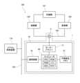
- the electric valve control device 70 has a nonvolatile memory 75, a communication device 76, a motor driver 77, and a computer 80, as shown in FIG.
- the motor-operated valve control device 70 controls the motor-operated valve 5 based on commands received from the air conditioner control device 110 .
- Non-volatile memory 75 stores data that must be retained even when the power is turned off.
- Non-volatile memory 75 is, for example, EEPROM or flash memory.
- the communication device 76 is communicably connected to the air conditioner control device 110 via the wired communication bus 120 .
- the air conditioning system 100 employs, for example, a communication method such as Local Interconnect Network (LIN) or Controller Area Network (CAN). Note that the communication device 76 may be connected to the air conditioner control device 110 so as to be capable of wireless communication.
- LIN Local Interconnect Network
- CAN Controller Area Network
- the motor driver 77 supplies drive current to the stepping motor 66 based on the pulse P input from the computer 80.
- the motor driver 77 is connected to terminals A1 and A2 of the coil 61c of the A-phase stator 61 and terminals B1 and B2 of the coil 62c of the B-phase stator 62.
- FIG. 4B shows an example of the correspondence between the pulse P and the drive current supplied by the motor driver 77.
- (+) indicates the supply of drive current from terminal A1 to terminal A2 or from terminal B1 to terminal B2, and (-) indicates drive current from terminal A2 to terminal A1. It indicates that a current or drive current is supplied from the terminal B2 to the terminal B1, and (0) indicates that no drive current is supplied.
- the motor driver 77 supplies drive current only to the coil 61c of the A-phase stator 61.
- motor driver 77 supplies drive current only to coil 62c of B-phase stator 62.
- FIG. When pulse P[2], P[4], P[6] or P[8] is input to motor driver 77, motor driver 77 controls coil 61c of A-phase stator 61 and coil 62c of B-phase stator 62. supply the drive current to
- the computer 80 is a microcomputer for embedded equipment in which a CPU, ROM, RAM, input/output interface (I/O), analog-digital converter (ADC), timer, etc. are incorporated in one package.
- Computer 80 may include non-volatile memory 75 , communication device 76 and motor driver 77 .
- Computer 80 may be connected to an external temperature sensor or an external analog-to-digital converter.
- a computer 80 is a control unit.
- the computer 80 controls the stepping motor 66. Specifically, the computer 80 inputs a pulse P to the motor driver 77 to rotate the rotor 41 .
- the computer 80 also acquires the voltage generated in the stator 60 by the rotation of the rotor 41 (the voltage electromagnetically induced in the stator 60). Specifically, when the motor driver 77 supplies the drive current only to the coil 61c of the A-phase stator 61 in response to the pulses P[1] and P[5], the computer 80 causes the coil of the B-phase stator 62 to A voltage VB developed between terminals B1 and B2 of 62c is obtained. When the motor driver 77 supplies the drive current only to the coil 62c of the B-phase stator 62 in response to the pulses P[3] and P[7], the computer 80 controls the terminal A1 of the coil 61c of the A-phase stator 61, Obtain the voltage VA occurring across A2.
- the waveform of the voltage VA and the waveform of the voltage VB when the stepping motor 66 is not out of step differs from the waveform of the voltage VA and the waveform of the voltage VB when the stepping motor 66 is out of step.
- Computer 80 determines whether stepping motor 66 has stepped out based on voltage VA and voltage VB.
- Computer 80 detects out-of-step of stepping motor 66 based on voltage VA and voltage VB.
- the waveforms of the voltage VA and the voltage VB when the rotor 41 is rotating are different from the waveforms of the voltage VA and the voltage VB when the rotor 41 is not rotating.
- Computer 80 determines whether rotor 41 has rotated based on voltage VA and voltage VB.
- Computer 80 detects the rotation of rotor 41 based on voltage VA and voltage VB.
- the motor-operated valve 5 may have a permanent magnet that rotates together with the rotor 41, and the motor-operated valve control device 70 may have a magnetic sensor that detects the rotation of the permanent magnet. Then, the computer 80 may determine whether the stepping motor 66 has stepped out and whether the rotor 41 has rotated based on the output signal of the magnetic sensor.
- the ROM of the computer 80 stores programs executed by the CPU and various setting values that do not need to be rewritten.
- the RAM of the computer 80 is a working memory used when the CPU executes programs.
- a RAM of the computer 80 stores a current valve opening degree Dc indicating the current valve opening degree of the electric valve 5 .
- the current valve opening degree Dc is copied from the RAM to the nonvolatile memory 75 when the electric valve control device 70 is powered off or shifted to sleep mode.
- the current valve opening degree Dc is copied from the nonvolatile memory 75 to the RAM when the electric valve control device 70 is powered on or returned from the sleep mode.
- the RAM of the computer 80 stores a counter C1.
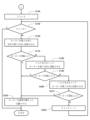
- FIG. 5 and 6 are flow charts showing an example of processing executed by a computer of the motor operated valve device of FIG.
- the motor-operated valve control device 70 shifts to the operation mode when the power is turned on or when it returns from the sleep mode.
- the motor operated valve controller 70 waits for a command from the air conditioner controller 110 in the operating mode.
- the motor-operated valve control device 70 receives a valve opening degree change command from the air conditioner control device 110, it executes the processing shown in the flowcharts of FIGS. 5 and 6 (hereinafter referred to as "valve opening degree change processing").
- the valve opening degree change command includes a target value of the valve opening degree of the electric valve 5 (target valve opening degree Dt).
- the motor-operated valve control device 70 rotates the rotor 41 to change the valve opening degree of the motor-operated valve 5 (S110). Specifically, the electric valve control device 70 inputs a pulse P to the motor driver 77 to control the stepping motor 66 so that the rotor 41 rotates. If the target valve opening degree Dt is smaller than the current valve opening degree Dc, the electric valve control device 70 inputs pulses P in ascending order so that the rotor 41 rotates in the valve closing direction. Alternatively, if the target valve opening degree Dt is greater than the current valve opening degree Dc, the electric valve control device 70 inputs the pulses P in descending order so that the rotor 41 rotates in the valve opening direction.
- the rotation direction of the rotor 41 at this time is called "first direction".
- the first direction is the rotation direction of the rotor 41 when changing the valve opening degree of the electric valve 5 from the current valve opening degree Dc to the target valve opening degree Dt in the valve opening degree changing process.
- the valve closing direction is the first direction.
- the valve opening direction is the first direction.
- the electric valve control device 70 determines whether the stepping motor 66 has stepped out. Specifically, the electric valve control device 70 determines whether the stepping motor 66 has stepped out based on the voltage VA and the voltage VB while controlling the stepping motor 66 so that the rotor 41 rotates in the first direction. It is determined whether or not (S120). The motor-operated valve control device 70 determines that the stepping motor 66 has not stepped out (N in S120), and if the valve opening degree of the motor-operated valve 5 has not reached the target valve opening degree Dt (N in S130). ), the input of the pulse P to the motor driver 77 is continued so that the rotor 41 rotates in the first direction (S110). When the valve opening degree of the electric valve 5 reaches the target valve opening degree Dt (Y in S130), the motor-operated valve control device 70 stores the target valve opening degree Dt in the RAM as the current valve opening degree Dc. End the modification process.
- the motor-operated valve control device 70 determines that the stepping motor 66 has stepped out (Y in S120)
- the motor-operated valve control device 70 performs an operation ( The number of repetitions of S150 to S220) is set in the counter C1 (S140).
- the number set in the counter C1 is three.
- the number set in the counter C1 is appropriately set according to the system in which the motor-operated valve device 1 is incorporated.
- the electric valve control device 70 rotates the rotor 41 in the second direction opposite to the first direction (S160). Specifically, the electric valve control device 70 inputs a pulse P to the motor driver 77 to control the stepping motor 66 so that the rotor 41 rotates in the second direction opposite to the first direction. Then, the electric valve control device 70 determines whether or not the rotor 41 has rotated based on the voltage VA and the voltage VB (S170).
- the motor-operated valve control device 70 determines that the rotor 41 is not rotating (N in S170), it increases the torque of the stepping motor 66 to rotate the rotor 41 in the second direction (S180). Specifically, when the rotor 41 does not rotate in the second direction even if the stepping motor 66 is controlled so that the rotor 41 rotates in the second direction, the motor-operated valve control device 70 supplies the drive current to the stepping motor 66. increase the The motor-operated valve control device 70 increases the drive current by a predetermined amount (for example, 50 mA) from the drive current supplied immediately before. As the drive current increases, the torque increases.
- a predetermined amount for example, 50 mA
- the electric valve control device 70 inputs a pulse P to the motor driver 77 to control the stepping motor 66 so that the rotor 41 rotates in the second direction. Then, the electric valve control device 70 determines whether or not the rotor 41 has rotated based on the voltage VA and the voltage VB (S190).
- the motor-operated valve control device 70 determines that the rotor 41 is not rotating (N in S190), it increases the torque of the stepping motor 66 to rotate the rotor 41 in the first direction (S200). Specifically, when the rotor 41 does not rotate in the second direction even if the stepping motor 66 is controlled so that the rotor 41 rotates in the second direction by increasing the drive current, the motor-operated valve control device 70 The drive current supplied to 66 is further increased. The motor-operated valve control device 70 increases the drive current by a predetermined amount (for example, 50 mA) from the drive current supplied immediately before.
- a predetermined amount for example, 50 mA
- the electric valve control device 70 inputs a pulse P to the motor driver 77 to control the stepping motor 66 so that the rotor 41 rotates in the first direction. Then, the electric valve control device 70 determines whether or not the rotor 41 has rotated based on the voltage VA and the voltage VB (S210).
- the electric valve control device 70 may reduce the rotational speed of the rotor 41 in steps S180 and S200 instead of increasing the drive current.
- the motor-operated valve control device 70 reduces the rotation speed by a predetermined amount (for example, 10 pps) from the previous rotation speed. As the rotational speed decreases, the torque increases.
- the motor-operated valve control device 70 determines that the rotor 41 is not rotating (N in S210), it decrements the counter C1 by 1 (S220) and returns to the determination of the counter C1 (S150).
- the motor-operated valve control device 70 determines that the rotor 41 has rotated (Y in S170, Y in S190, or Y in S210), it positions the rotor 41 at the reference position Rx (S230). Specifically, the electric valve control device 70 sets the magnitude of the drive current supplied to the stepping motor 66 to an initial value. The electric valve control device 70 inputs a pulse P to the motor driver 77 to control the stepping motor 66 so that the rotor 41 rotates in the valve closing direction, thereby positioning the rotor 41 at the reference position Rx. For example, the electric valve control device 70 inputs to the motor driver 77 the number of pulses P required to rotate the rotor 41 from the fully open position Rz to the reference position Rx. Then, the electric valve control device 70 terminates the valve opening change process.
- the motor-operated valve control device 70 determines that the motor-operated valve 5 cannot be restored from the locked state to the normal state, sets a failure flag, and ends the valve opening change process. do.
- the failure flag is set, the motor-operated valve control device 70 executes the process when the motor-operated valve 5 fails. It should be noted that a detailed description of the process when a failure occurs is omitted because it is beyond the scope of the present invention.
- the motor-operated valve device 1 has the motor-operated valve 5 and the motor-operated valve control device 70 .
- the electric valve 5 has a valve body 30 , a stepping motor 66 , and a drive mechanism 40 that moves the valve body 30 according to rotation of a rotor 41 of the stepping motor 66 .
- a motorized valve controller 70 has a computer 80 that controls the stepper motor 66 .
- the computer 80 detects stepping out of the stepping motor 66 while controlling the stepping motor 66 so that the rotor 41 rotates in the first direction to change the valve opening of the electric valve 5, (A)
- the stepping motor 66 is controlled so that the rotor 41 rotates in a second direction opposite to the first direction.
- the computer 80 controls the stepping motor 66 to rotate the rotor 41 in the second direction but the rotor 41 does not rotate in the second direction
- the torque of the stepping motor 66 is increased and the rotor 41 is rotated. controls the stepping motor 66 to rotate in the second direction.
- the computer 80 increases the torque to rotate the rotor 41 in the second direction, so that foreign matter can be discharged from the drive mechanism 40 more effectively.
- the computer 80 (C) increases the torque of the stepping motor 66 and controls the stepping motor 66 so that the rotor 41 rotates in the second direction, the rotor 41 does not rotate in the second direction.
- the stepping motor 66 is controlled so that it is increased further and the rotor 41 rotates in the first direction. In this way, the computer 80 further increases the torque to reverse the direction of rotation of the rotor 41 , so that foreign matter can be more effectively discharged from the drive mechanism 40 .
- the computer 80 terminates the operations (A), (B) and (C) and sets the rotor 41 as the reference. Control the stepping motor 66 to position it at the position Rx. In this way, the computer 80 positions the rotor 41 at the reference position Rx after the motor-operated valve 5 returns from the locked state to the normal state, thereby eliminating stepping out of the stepping motor 66 .
- the computer 80 repeats the operations of (A), (B) and (C).
- the computer 80 repeats the operations (A), (B) and (C) a predetermined number of times, the operations (A), (B) and (C) are completed. In this manner, the computer 80 repeats the operations (A), (B), and (C), thereby increasing the possibility that the motor-operated valve 5 returns to the normal state. If the computer 80 repeats the operations (A), (B) and (C) a predetermined number of times and the motor-operated valve 5 does not return to the normal state, the operations (A), (B) and (C) are performed. is ended, it is possible to prevent the operation of returning the motor-operated valve 5 to the normal state from continuing for a long time.
- the computer 80 increases the torque by increasing the drive current supplied to the stepping motor 66 . Then, the computer 80 repeats the operations of (A), (B) and (C), and when the driving current exceeds a predetermined current upper limit determination threshold (for example, 800 mA), (A), (B) and The operation of (C) may be terminated. In this manner, the computer 80 repeats the operations (A), (B), and (C), thereby increasing the possibility that the motor-operated valve 5 returns to the normal state. Further, when the drive current supplied to the stepping motor 66 exceeds the current upper limit determination threshold value, the computer 80 terminates the operations (A), (B) and (C), so that the motor operated valve 5 is kept in the normal state. It is possible to prevent the operation to return to the continuation for a long time.
- the current upper limit determination threshold is set based on the maximum current that the motor driver 77 can supply to the stepping motor 66 .
- the computer 80 may increase the torque by decreasing the rotational speed of the rotor 41. Then, the computer 80 repeats the operations of (A), (B) and (C), and when the rotation speed becomes equal to or lower than the speed lower limit determination threshold value (for example, 0 pps), (A), (B) and ( You may make it complete
- the speed lower limit determination threshold value for example, 0 pps
- the computer 80 terminates the operations (A), (B) and (C), thereby returning the motor-operated valve 5 to its normal state. It is possible to prevent the action to be made from continuing for a long time.
- the stepping motor 66 may be controlled such that the drive current supplied to the stepping motor 66 is maximized and the rotor 41 rotates in the second direction.
- the drive current supplied by the computer 80 to the stepping motor 66 is maximized to increase the torque, and the rotor 41 is rotated in the second direction, thereby effectively discharging the foreign matter from the drive mechanism 40. can be done.
- the computer 80 sets the drive current supplied to the stepping motor 66 to the maximum value and causes the stepping motor 66 to rotate so that the rotor 41 rotates in the second direction.
- the stepping motor 66 may be controlled so that the drive current is maximized and the rotor 41 rotates in the first direction.
- the computer 80 maximizes the drive current to increase the torque and reverses the direction of rotation of the rotor 41 , so that foreign matter can be more effectively discharged from the drive mechanism 40 .
- the maximum value is the maximum value of the current that the motor driver 77 can supply to the stepping motor 66 .
- each term indicating a shape such as “cylinder” or “cylinder” is also used for a member or a portion of a member that substantially has the shape of the term.
- a “cylindrical member” includes a cylindrical member and a substantially cylindrical member.
Landscapes
- Engineering & Computer Science (AREA)
- General Engineering & Computer Science (AREA)
- Mechanical Engineering (AREA)
- Physics & Mathematics (AREA)
- Thermal Sciences (AREA)
- Electrically Driven Valve-Operating Means (AREA)
Abstract
Description
Claims (10)
- 電動弁を制御する電動弁制御装置であって、
前記電動弁が、弁体と、ステッピングモーターと、前記ステッピングモーターのローターの回転に応じて前記弁体を移動させる駆動機構と、を有し、
前記電動弁制御装置が、前記ステッピングモーターを制御する制御部を有し、
前記制御部が、前記電動弁の弁開度を変更するために前記ローターが第1方向に回転するように前記ステッピングモーターを制御しているときに前記ステッピングモーターの脱調を検出すると、(A)前記ローターが前記第1方向と反対の第2方向に回転するように前記ステッピングモーターを制御することを特徴とする電動弁制御装置。 - 前記制御部が、(B)前記ローターが前記第2方向に回転するように前記ステッピングモーターを制御しても前記ローターが前記第2方向に回転しないとき、前記ステッピングモーターのトルクを大きくしかつ前記ローターが前記第2方向に回転するように前記ステッピングモーターを制御する、請求項1に記載の電動弁制御装置。
- 前記制御部が、(C)前記トルクを大きくしかつ前記ローターが前記第2方向に回転するように前記ステッピングモーターを制御しても前記ローターが前記第2方向に回転しないとき、前記トルクをさらに大きくしかつ前記ローターが前記第1方向に回転するように前記ステッピングモーターを制御する、請求項2に記載の電動弁制御装置。
- 前記制御部が、前記(A)、(B)および(C)のいずれかの動作において前記ローターが回転すると、前記(A)、(B)および(C)の動作を終了し、前記ローターを基準位置に位置付けるように前記ステッピングモーターを制御する、請求項3に記載の電動弁制御装置。
- 前記制御部が、
前記(A)、(B)および(C)の動作を繰り返し、
前記(A)、(B)および(C)の動作を所定の回数繰り返したとき、前記(A)、(B)および(C)の動作を終了する、請求項4に記載の電動弁制御装置。 - 前記制御部が、
前記ステッピングモーターに供給する駆動電流を大きくすることにより前記トルクを大きくし、
前記(A)、(B)および(C)の動作を繰り返し、
前記駆動電流が電流上限判定しきい値を超えたとき、前記(A)、(B)および(C)の動作を終了する、請求項4または請求項5に記載の電動弁制御装置。 - 前記制御部が、
前記ローターの回転速度を小さくすることにより前記トルクを大きくし、
前記(A)、(B)および(C)の動作を繰り返し、
前記回転速度が速度下限判定しきい値以下になったとき、前記(A)、(B)および(C)の動作を終了する、請求項4または請求項5に記載の電動弁制御装置。 - 前記制御部が、(B1)前記ローターが前記第2方向に回転するように前記ステッピングモーターを制御しても前記ローターが前記第2方向に回転しないとき、前記ステッピングモーターに供給する駆動電流を最大値にしかつ前記ローターが前記第2方向に回転するように前記ステッピングモーターを制御する、請求項1に記載の電動弁制御装置。
- 前記制御部が、(C1)前記駆動電流を最大値にしかつ前記ローターが前記第2方向に回転するように前記ステッピングモーターを制御しても前記ローターが前記第2方向に回転しないとき、前記駆動電流を最大値にしかつ前記ローターが前記第1方向に回転するように前記ステッピングモーターを制御する、請求項8に記載の電動弁制御装置。
- 弁体と、ステッピングモーターと、前記ステッピングモーターのローターの回転に応じて前記弁体を移動させる駆動機構と、を有する電動弁と、
請求項1に記載の電動弁制御装置と、を有する電動弁装置。
Priority Applications (3)
| Application Number | Priority Date | Filing Date | Title |
|---|---|---|---|
| KR1020247001386A KR20240021922A (ko) | 2021-11-15 | 2022-10-24 | 전동밸브 제어 장치 및 전동밸브 장치 |
| CN202280047563.9A CN118159761A (zh) | 2021-11-15 | 2022-10-24 | 电动阀控制装置及电动阀装置 |
| EP22892565.7A EP4435303A1 (en) | 2021-11-15 | 2022-10-24 | Electric valve control device and electric valve device |
Applications Claiming Priority (2)
| Application Number | Priority Date | Filing Date | Title |
|---|---|---|---|
| JP2021-185917 | 2021-11-15 | ||
| JP2021185917A JP2023073091A (ja) | 2021-11-15 | 2021-11-15 | 電動弁制御装置および電動弁装置 |
Publications (1)
| Publication Number | Publication Date |
|---|---|
| WO2023085065A1 true WO2023085065A1 (ja) | 2023-05-19 |
Family
ID=86335720
Family Applications (1)
| Application Number | Title | Priority Date | Filing Date |
|---|---|---|---|
| PCT/JP2022/039504 WO2023085065A1 (ja) | 2021-11-15 | 2022-10-24 | 電動弁制御装置および電動弁装置 |
Country Status (5)
| Country | Link |
|---|---|
| EP (1) | EP4435303A1 (ja) |
| JP (1) | JP2023073091A (ja) |
| KR (1) | KR20240021922A (ja) |
| CN (1) | CN118159761A (ja) |
| WO (1) | WO2023085065A1 (ja) |
Citations (5)
| Publication number | Priority date | Publication date | Assignee | Title |
|---|---|---|---|---|
| JP2012229735A (ja) * | 2011-04-26 | 2012-11-22 | Kawaden:Kk | 電動弁 |
| JP2013200046A (ja) * | 2012-03-23 | 2013-10-03 | Noritz Corp | 風呂給湯システムおよび三方弁駆動装置 |
| JP2015052329A (ja) * | 2013-09-05 | 2015-03-19 | 株式会社キッツ | 噛み込み検知機能付きバルブ用電動アクチュエータとその異常検知方法 |
| WO2019130928A1 (ja) | 2017-12-26 | 2019-07-04 | 株式会社不二工機 | 電動弁制御装置およびそれを備えた電動弁装置 |
| WO2019187866A1 (ja) * | 2018-03-26 | 2019-10-03 | 株式会社不二工機 | 電動弁 |
-
2021
- 2021-11-15 JP JP2021185917A patent/JP2023073091A/ja active Pending
-
2022
- 2022-10-24 KR KR1020247001386A patent/KR20240021922A/ko active Search and Examination
- 2022-10-24 CN CN202280047563.9A patent/CN118159761A/zh active Pending
- 2022-10-24 WO PCT/JP2022/039504 patent/WO2023085065A1/ja active Application Filing
- 2022-10-24 EP EP22892565.7A patent/EP4435303A1/en active Pending
Patent Citations (5)
| Publication number | Priority date | Publication date | Assignee | Title |
|---|---|---|---|---|
| JP2012229735A (ja) * | 2011-04-26 | 2012-11-22 | Kawaden:Kk | 電動弁 |
| JP2013200046A (ja) * | 2012-03-23 | 2013-10-03 | Noritz Corp | 風呂給湯システムおよび三方弁駆動装置 |
| JP2015052329A (ja) * | 2013-09-05 | 2015-03-19 | 株式会社キッツ | 噛み込み検知機能付きバルブ用電動アクチュエータとその異常検知方法 |
| WO2019130928A1 (ja) | 2017-12-26 | 2019-07-04 | 株式会社不二工機 | 電動弁制御装置およびそれを備えた電動弁装置 |
| WO2019187866A1 (ja) * | 2018-03-26 | 2019-10-03 | 株式会社不二工機 | 電動弁 |
Also Published As
| Publication number | Publication date |
|---|---|
| EP4435303A1 (en) | 2024-09-25 |
| JP2023073091A (ja) | 2023-05-25 |
| KR20240021922A (ko) | 2024-02-19 |
| CN118159761A (zh) | 2024-06-07 |
Similar Documents
| Publication | Publication Date | Title |
|---|---|---|
| JP2024103593A (ja) | 電動弁制御装置および電動弁装置、ならびに、電動弁の制御方法 | |
| WO2023085065A1 (ja) | 電動弁制御装置および電動弁装置 | |
| WO2023067988A1 (ja) | 電動弁制御装置および電動弁装置 | |
| WO2023090107A1 (ja) | 電動弁制御装置および電動弁装置 | |
| JP7345922B2 (ja) | 電動弁、その制御方法、およびその製造方法 | |
| WO2023149146A1 (ja) | 電動弁制御装置および電動弁装置 | |
| JP7479714B2 (ja) | 電動弁制御装置および電動弁装置、ならびに、電動弁の制御方法 | |
| WO2024202317A1 (ja) | 電動弁制御装置および電動弁装置、ならびに、電動弁の制御方法 | |
| WO2024180876A1 (ja) | 電動弁制御装置および電動弁装置、ならびに、電動弁の制御方法 | |
| WO2024176593A1 (ja) | 電動弁制御装置および電動弁装置、ならびに、電動弁の制御方法 | |
| JP7546940B2 (ja) | 電動弁制御装置および電動弁装置 | |
| WO2023233939A1 (ja) | 電動弁制御装置および電動弁装置 | |
| WO2023203967A1 (ja) | 電動弁 | |
| CN115711318A (zh) | 电动阀、该电动阀的控制方法及其制造方法 |
Legal Events
| Date | Code | Title | Description |
|---|---|---|---|
| 121 | Ep: the epo has been informed by wipo that ep was designated in this application |
Ref document number: 22892565 Country of ref document: EP Kind code of ref document: A1 |
|
| DPE2 | Request for preliminary examination filed before expiration of 19th month from priority date (pct application filed from 20040101) | ||
| WWE | Wipo information: entry into national phase |
Ref document number: 202280047563.9 Country of ref document: CN |
|
| ENP | Entry into the national phase |
Ref document number: 20247001386 Country of ref document: KR Kind code of ref document: A |
|
| WWE | Wipo information: entry into national phase |
Ref document number: 1020247001386 Country of ref document: KR |
|
| WWE | Wipo information: entry into national phase |
Ref document number: 2022892565 Country of ref document: EP |
|
| ENP | Entry into the national phase |
Ref document number: 2022892565 Country of ref document: EP Effective date: 20240617 |