WO2023053754A1 - 光接続部品 - Google Patents
光接続部品 Download PDFInfo
- Publication number
- WO2023053754A1 WO2023053754A1 PCT/JP2022/030963 JP2022030963W WO2023053754A1 WO 2023053754 A1 WO2023053754 A1 WO 2023053754A1 JP 2022030963 W JP2022030963 W JP 2022030963W WO 2023053754 A1 WO2023053754 A1 WO 2023053754A1
- Authority
- WO
- WIPO (PCT)
- Prior art keywords
- ferrule
- flange
- optical
- optical connector
- sleeve
- Prior art date
- Legal status (The legal status is an assumption and is not a legal conclusion. Google has not performed a legal analysis and makes no representation as to the accuracy of the status listed.)
- Ceased
Links
Images


Classifications
-
- G—PHYSICS
- G02—OPTICS
- G02B—OPTICAL ELEMENTS, SYSTEMS OR APPARATUS
- G02B6/00—Light guides; Structural details of arrangements comprising light guides and other optical elements, e.g. couplings
- G02B6/24—Coupling light guides
- G02B6/36—Mechanical coupling means
- G02B6/38—Mechanical coupling means having fibre to fibre mating means
- G02B6/3807—Dismountable connectors, i.e. comprising plugs
- G02B6/3873—Connectors using guide surfaces for aligning ferrule ends, e.g. tubes, sleeves, V-grooves, rods, pins, balls
- G02B6/3874—Connectors using guide surfaces for aligning ferrule ends, e.g. tubes, sleeves, V-grooves, rods, pins, balls using tubes, sleeves to align ferrules
-
- G—PHYSICS
- G02—OPTICS
- G02B—OPTICAL ELEMENTS, SYSTEMS OR APPARATUS
- G02B6/00—Light guides; Structural details of arrangements comprising light guides and other optical elements, e.g. couplings
- G02B6/24—Coupling light guides
- G02B6/36—Mechanical coupling means
- G02B6/38—Mechanical coupling means having fibre to fibre mating means
- G02B6/3807—Dismountable connectors, i.e. comprising plugs
- G02B6/381—Dismountable connectors, i.e. comprising plugs of the ferrule type, e.g. fibre ends embedded in ferrules, connecting a pair of fibres
- G02B6/3818—Dismountable connectors, i.e. comprising plugs of the ferrule type, e.g. fibre ends embedded in ferrules, connecting a pair of fibres of a low-reflection-loss type
- G02B6/3821—Dismountable connectors, i.e. comprising plugs of the ferrule type, e.g. fibre ends embedded in ferrules, connecting a pair of fibres of a low-reflection-loss type with axial spring biasing or loading means
-
- G—PHYSICS
- G02—OPTICS
- G02B—OPTICAL ELEMENTS, SYSTEMS OR APPARATUS
- G02B6/00—Light guides; Structural details of arrangements comprising light guides and other optical elements, e.g. couplings
- G02B6/24—Coupling light guides
- G02B6/36—Mechanical coupling means
- G02B6/38—Mechanical coupling means having fibre to fibre mating means
- G02B6/3807—Dismountable connectors, i.e. comprising plugs
- G02B6/381—Dismountable connectors, i.e. comprising plugs of the ferrule type, e.g. fibre ends embedded in ferrules, connecting a pair of fibres
- G02B6/3825—Dismountable connectors, i.e. comprising plugs of the ferrule type, e.g. fibre ends embedded in ferrules, connecting a pair of fibres with an intermediate part, e.g. adapter, receptacle, linking two plugs
-
- G—PHYSICS
- G02—OPTICS
- G02B—OPTICAL ELEMENTS, SYSTEMS OR APPARATUS
- G02B6/00—Light guides; Structural details of arrangements comprising light guides and other optical elements, e.g. couplings
- G02B6/24—Coupling light guides
- G02B6/36—Mechanical coupling means
- G02B6/38—Mechanical coupling means having fibre to fibre mating means
- G02B6/3807—Dismountable connectors, i.e. comprising plugs
- G02B6/3869—Mounting ferrules to connector body, i.e. plugs
- G02B6/3871—Ferrule rotatable with respect to plug body, e.g. for setting rotational position ; Fixation of ferrules after rotation
-
- G—PHYSICS
- G02—OPTICS
- G02B—OPTICAL ELEMENTS, SYSTEMS OR APPARATUS
- G02B6/00—Light guides; Structural details of arrangements comprising light guides and other optical elements, e.g. couplings
- G02B6/24—Coupling light guides
- G02B6/36—Mechanical coupling means
- G02B6/38—Mechanical coupling means having fibre to fibre mating means
- G02B6/3807—Dismountable connectors, i.e. comprising plugs
- G02B6/381—Dismountable connectors, i.e. comprising plugs of the ferrule type, e.g. fibre ends embedded in ferrules, connecting a pair of fibres
- G02B6/3812—Dismountable connectors, i.e. comprising plugs of the ferrule type, e.g. fibre ends embedded in ferrules, connecting a pair of fibres having polarisation-maintaining light guides
-
- G—PHYSICS
- G02—OPTICS
- G02B—OPTICAL ELEMENTS, SYSTEMS OR APPARATUS
- G02B6/00—Light guides; Structural details of arrangements comprising light guides and other optical elements, e.g. couplings
- G02B6/24—Coupling light guides
- G02B6/36—Mechanical coupling means
- G02B6/38—Mechanical coupling means having fibre to fibre mating means
- G02B6/3807—Dismountable connectors, i.e. comprising plugs
- G02B6/3873—Connectors using guide surfaces for aligning ferrule ends, e.g. tubes, sleeves, V-grooves, rods, pins, balls
- G02B6/3885—Multicore or multichannel optical connectors, i.e. one single ferrule containing more than one fibre, e.g. ribbon type
Definitions
- Non-Patent Document 1 discloses an optical connector that employs an Oldham coupling structure in order to achieve both a ferrule floating structure and a rotation-preventing structure.
- the floating structure is a structure in which the installation position of internal parts including the ferrule can be changed by pushing the ferrule into the connector housing.
- the rotation restraint structure is a structure that restricts the rotation of the ferrule about the central axis of the ferrule with respect to the connector housing.
- the Oldham coupling structure which simultaneously realizes a floating structure and a rotation restraint structure, intervenes a coupling member between the flange to which the ferrule is attached and the connector housing, and provides a clearance between the connector housing and the coupling member.
- the coupling member is provided with a degree of freedom in the vertical direction
- the ferrule is provided with a degree of freedom in the lateral direction by providing a clearance between the connector housing and the flange.
- the optical connection component of the present disclosure includes an optical connector and an adapter.
- the optical connector includes an optical fiber, a front end, a rear end opposite the front end, a ferrule assembly, a housing, and an elastic member.
- the adapter has an opening for receiving the front end of the optical connector, an alignment sleeve, and a sleeve holder for holding the alignment sleeve in place.
- the optical fiber includes a glass fiber and a resin coating covering the glass fiber.
- the ferrule assembly has a ferrule and a retainer. The ferrule is fixed to the tip portion of the glass fiber exposed from the resin coating of the optical fiber.
- the holding portion is provided with a flange to which the rear end of the ferrule is fixed.
- the housing has an inner wall surface, a flat surface and a positioning portion.
- the inner wall defines an inner space in which at least the holding portion of the ferrule assembly is accommodated.
- the flat surface constitutes part of the inner wall surface and is provided at a position facing part of the outer peripheral surface of the flange.
- the positioning portion limits movement of the holding portion within the internal space.
- the elastic member biases the flange toward the positioning portion.
- the flange is biased toward the positioning portion.
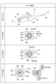
- FIG. 1 is a diagram for explaining a schematic structure of an optical connector forming part of an optical connection component of the present disclosure.
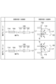
- 2A and 2B are diagrams for explaining various structures of ferrule assemblies applicable to the optical connector shown in FIG.
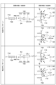
- FIG. 3 is a diagram for explaining the cross-sectional structure of each part of the optical connection component of the present disclosure and the positional relationship between the ferrule assembly and the alignment sleeve housed inside the optical component.
- FIG. 4 is a first installation state showing misalignment between the ferrule assembly and the alignment sleeve, which are the main portions of the optical connection component of the present disclosure, for explaining the installation state of the main portions before and during contact. It is a diagram.
- FIG. 1 is a diagram for explaining a schematic structure of an optical connector forming part of an optical connection component of the present disclosure.
- 2A and 2B are diagrams for explaining various structures of ferrule assemblies applicable to the optical connector shown in FIG.
- FIG. 3 is a diagram for explaining the cross-section
- FIG. 5 is a second installation state showing angular misalignment between the ferrule assembly and the alignment sleeve, which are the main portions of the optical connection component of the present disclosure, for explaining the installation state of the main portions before and during contact. It is a diagram.
- FIG. 6 is a diagram for explaining the mounting operation after the main parts of the optical connection component of the present disclosure are brought into contact with each other.
- the present disclosure has been made to solve the problems described above, and an optical connection component having a structure for realizing rotational positioning of a ferrule housed in an optical connector while avoiding complication of the structure. is intended to provide
- the optical connection component of the present disclosure is (1) It has an optical connector and an adapter.
- the optical connector includes an optical fiber, a front end, a rear end opposite the front end, a ferrule assembly, a housing, and an elastic member.
- the adapter has an opening for receiving the front end of the optical connector, an alignment sleeve, and a sleeve holder for holding the alignment sleeve in place.
- the optical fiber includes a glass fiber and a resin coating covering the glass fiber.
- the ferrule assembly has a ferrule and a retainer. The ferrule is fixed to the tip portion of the glass fiber exposed from the resin coating of the optical fiber.
- the holding portion is provided with a flange to which the rear end of the ferrule is fixed.
- the housing has an inner wall surface, a flat surface and a positioning portion.
- the inner wall defines an inner space in which at least the holding portion of the ferrule assembly is accommodated.
- the flat surface constitutes part of the inner wall surface and is provided at a position facing part of the outer peripheral surface of the flange.
- the positioning portion limits movement of the holding portion within the internal space.
- the elastic member biases the flange toward the positioning portion.
- the ferrule when the front end of the ferrule and the alignment sleeve or sleeve holder in the adapter are not in contact with each other, the ferrule is rotatably positioned about the first central axis.
- the flange is biased toward the portion.
- the flange in an off-axis state where the front end of the ferrule and the alignment sleeve or sleeve holder in the adapter are in contact and the outer peripheral surface of the flange is in contact with the flat surface, the flange is biased toward the positioning portion.
- the ferrule assembly When the ferrule assembly, especially the flange, rotates with respect to the housing, it causes angular misalignment in the rotational direction of the multi-core optical fiber.
- the alignment sleeve in the adapter or the The vertical component of the frictional force applied to the ferrule in contact with the sleeve holder causes the rear end of the ferrule assembly to swing toward the inner wall surface of the housing.
- the rotational positioning of the ferrule is achieved by bringing the outer peripheral surface of the flange into contact with the flat surface of the housing.
- the ferrule assembly is retracted from the front end of the housing toward the rear end to release the rotational positioning state, thereby realizing a floating structure for the entire ferrule assembly. be done.
- the ferrule assembly is in an external force free state.
- the optical connector has a floating structure, and the floating structure is formed by pushing the ferrule from the front end toward the rear end of the optical connector, thereby forming a ferrule assembly within the housing. The installation position of is changed.
- the outer shape of the flange of the holding portion may be a square when viewed from the front end to the rear end of the optical connector.
- a "quadrilateral" is a type of polygon that indicates a portion of a plane surrounded by four straight lines.
- the outer shape of the flange may have a D-shaped structure in which a pair of corners sandwiching at least one of the facing sides are curved. Also in this case, since the contact state between a portion of the outer peripheral surface of the flange and the flat surface is stable, the rotation of the entire ferrule assembly about the first central axis of the ferrule is effectively suppressed.
- the optical fiber to which the optical connector is attached at the tip portion may be any one of a multi-core optical fiber, a polarization-maintaining optical fiber, and a bundle fiber.
- the optical connector has a structure capable of suppressing rotation of a ferrule assembly whose main part is housed in a housing. Therefore, highly accurate positioning is possible for optical fibers that require positioning in the rotational direction, and as a result, optical fiber connection with low loss is realized.
- the material of the housing of the optical connector may be resin.
- a resin material as the material of the housing, it is possible to change the installation state of the flange and to position the ferrule in rotation using deformation of the housing. That is, by changing the installation state of the flange and deforming the housing, it is possible to intentionally achieve a state in which the center axis of the biased ferrule assembly and the center axis of the sleeve or sleeve holder are not aligned.
- the material of the flange of the holding portion may be metal. Since the outer peripheral surface (flat surface) of the flange is less likely to change due to deformation of the housing or the like, the accuracy of rotational positioning is improved.
- the material of the flange of the holding portion may be resin. In this case, damage to the housing due to collision of the optical connector with respect to the adapter is small, so deterioration of the rotational positioning function is effectively suppressed.
- the optical connection component of the present disclosure is (9) An optical connector and an adapter are provided.
- An optical connector has an optical fiber, a ferrule assembly, a housing, and an elastic member.
- the adapter has an aperture, an alignment sleeve, and a sleeve holder.
- the optical connector further includes a front end and a rear end opposite the front end.
- An optical fiber includes a glass fiber and a resin coating covering the glass fiber.
- the ferrule assembly includes a ferrule fixed to the tip portion of the glass fiber exposed from the resin coating, and a holding portion to which the rear end of the ferrule is fixed and provided with a flange.
- the housing includes an inner wall surface defining an inner space in which the holding portion is accommodated, a flat surface forming a part of the inner wall surface and facing a part of the outer peripheral surface of the flange, and a flat surface in the inner space. and a positioning portion that limits movement of the retainer in the.
- the elastic member biases the flange toward the positioning portion.
- the opening accommodates the front end of the optical connector.
- a sleeve holder holds the alignment sleeve in place.
- the ferrule when the front end of the ferrule and the alignment sleeve or sleeve holder in the adapter are not in contact with each other, the ferrule is attached to the positioning portion in a rotatable state about the first central axis.
- the flange is biased toward.
- the optical connection component of the present disclosure is (10) An optical connector and an adapter are provided.
- An optical connector has an optical fiber, a ferrule assembly, a housing, and an elastic member.
- the adapter has an aperture, an alignment sleeve, and a sleeve holder.
- the optical connector further includes a front end and a rear end opposite the front end.
- An optical fiber includes a glass fiber and a resin coating covering the glass fiber.
- the ferrule assembly includes a ferrule fixed to the tip portion of the glass fiber exposed from the resin coating, and a holding portion to which the rear end of the ferrule is fixed and provided with a flange.
- the housing includes an inner wall surface defining an inner space in which the holding portion is accommodated, a flat surface forming a part of the inner wall surface and facing a part of the outer peripheral surface of the flange, and a flat surface in the inner space.
- the elastic member biases the flange toward the positioning portion.
- the opening accommodates the front end of the optical connector.
- a sleeve holder holds the alignment sleeve in place.
- the flange is biased toward the locator in an off-axis condition where the forward end of the ferrule and the alignment sleeve or sleeve holder in the adapter are in contact and the outer peripheral surface of the flange contacts a flat surface.
- FIG. 1 is a diagram for explaining a schematic structure of an optical connector forming part of the optical connection component of the present disclosure.
- a push-pull optical connector 10 is shown as an example of an optical connector that constitutes a part of the optical connection component of the present disclosure.
- An example is shown.
- an optical connector 10 including an end face of MCF50A, which is a multi-core optical fiber is provided as an example of an optical fiber 50 requiring alignment to which a ferrule 110 is attached.
- the third stage referred to as "connector front face 2" in FIG.
- optical fiber 50 to which the ferrule 110 is attached is the optical connector 10 including the end face of the polarization maintaining optical fiber PMF 50B.
- a front view is shown.
- a front view and a cross-sectional view of a bundle fiber 50C in which a plurality of single-core optical fibers are bundled are shown at the bottom (referred to as "connector front face 3" in FIG. 1).
- a ferrule 110 is attached to the glass fiber 51 from which the resin coating has been removed, which corresponds to the tip portion including the end face of the optical fiber 50 , and the optical fiber 50 extending from the rear housing 30 is attached to the rear housing 30 .
- a boot 40 is attached to protect the As shown in FIG. 2, the ferrule assembly 100 includes a ferrule 110 attached to the tip portion of the glass fiber 51 from which the resin coating has been removed, and a holding portion composed of a flange 130 and a sleeve 120. , the rear end of the ferrule is inserted into the sleeve 120 .
- the MCF 50A comprises a plurality of cores 52A each extending along the fiber axis AX coinciding with the central axis of the MCF 50A, and a common clad 53A surrounding each of the plurality of cores 52A.
- a line LA indicates the azimuth at a rotation angle of 0°, which is the reference azimuth for rotational alignment of the MCF 50A.
- Line L R indicates the installation reference line for ferrule assembly 100 along the edge of flange 130 . In the ferrule assembly 100 including the MCF 50A after alignment, the lines LA and LR are parallel.
- the PMF 50B includes a core 52B extending along the fiber axis AX coinciding with the central axis of the PMF 50B, stress-applying portions 54 arranged to sandwich the core 52B, and a common clad surrounding the core 52B and the stress-applying portions 54, respectively. 53B and.
- the lines LA and LR are parallel.
- the ferrule 110 integrally attached to the tip portion of the optical fiber 500, the sleeve 120 into which the ferrule 110 is inserted, and the flange 130 are shown.
- Each of the plurality of single-core optical fibers 500 is composed of a glass fiber 510 and a resin coating, and each glass fiber 510 has a core 520 and a clad 530 .
- a glass fiber 510 bundled by a ferrule 110 constitutes a glass fiber 51C.
- the arrangement of the core 520 in a state in which the plurality of glass fibers 510 are bundled substantially corresponds to the core arrangement of the MCF 50A described above.
- the line LA and the line LR are parallel.
- FIG. 2 is a diagram for explaining various structures of ferrule assemblies applicable to the optical connector shown in FIG. 2 (indicated as "before assembly” in FIG. 2) shows an example in which a holding portion for fixing the rear end of the ferrule 110 is composed of a flange 130 and a sleeve 120, and a flange portion 130A and a sleeve portion 120A. Integral retainer 550 is shown. 2 (denoted as “after assembly” in FIG. 2) shows an example in which the rear end of the ferrule 110 is fixed by a holding portion composed of a flange 130 and a sleeve 120. As shown in FIG.
- a ferrule 110 is attached to the tip portion of the glass fiber 51 of the optical fiber 50 from which the resin coating has been removed.
- the flange 130 is provided with a through hole connecting the front flange opening 130a and the rear flange opening 130b
- the sleeve 120 is also provided with a through hole connecting the front sleeve opening 120a and the rear sleeve opening 120b.
- ferrule assembly 100 shown in the lower part of FIG. 2 is obtained.
- the integrated holding portion 550 has a flange portion 130A corresponding to the flange 130 and a sleeve portion 120B corresponding to the sleeve 120.
- Flange 130 may have an outer peripheral surface that is at least partially flat. The same applies to the flange portion 130A of the integrated holding portion 550.
- the shape of the end surface of the flange 130, where the front flange opening 130a and the rear flange opening 130b are located may be square or triangular.
- the end face shape of the flange 130 includes a D-shaped structure in which a pair of corners sandwiching at least one of the opposing sides are curved.
- the material of the flange 130 or the flange portion of the integrated holding portion 550 may be metal or resin.
- a metal flange is employed, the flat outer peripheral surface of the flange is less likely to change due to deformation of the housing or the like, so an improvement in rotational positioning accuracy can be expected.
- a resin flange is used, it is expected that deterioration of the rotational positioning function will be suppressed, because the damage caused by the collision of the flange with the housing due to attachment and detachment of the optical connector to the adapter is small.
- the optical connection component of the present disclosure includes an optical connector 10 mounted with an optical fiber 50 such as the MCF 50A, PMF 50B, and bundle fiber 50C described above, which requires rotational positioning of the fiber end face during optical connection.
- an optical connector that realizes stable optical connection with low connection loss.
- the first requirement is the rotational positioning of the ferrule when the optical connector is attached to the adapter.
- the second requirement is to realize a floating state in which no external force is transmitted to the ferrule.
- the number of parts is increased from the standard optical connector, and by strictly controlling the manufacturing accuracy of the parts, the ferrule rotation suppressing structure and A floating structure is realized.
- Non-Patent Document 1 there is a problem that the processing cost and the like increase as the structure becomes more complicated.
- the optical connection component of the present disclosure makes it possible to achieve both a ferrule rotation suppression structure and a floating structure with a simple structure.
- An LC connector will be described below as an example of the optical connector 10 .
- FIG. 3 illustrates the cross-sectional structure of each part of the optical connection component of the present disclosure (denoted as “internal structure” in FIG. 3), and the positional relationship between the ferrule assembly and the alignment sleeve housed inside the optical component.
- FIG. 3 illustrates the upper part of FIG. 3 (denoted as “optical connector” in FIG. 3) is a cross-sectional view of the optical connector 10 taken along line II shown in the uppermost part of FIG.
- the front end of the optical connector 10 is inserted into one opening of the adapter, that is, immediately before the ferrule is inserted into the alignment sleeve. state is shown.
- the lower part of FIG. 3 shows the positional relationship between the alignment sleeve and the ferrule assembly immediately before insertion.
- the optical connector 10 has a structure that is attached to the adapter 600 by inserting the ferrule 110 into the alignment sleeve 700 inside the adapter 600 .
- the optical connector 10 has a housing for stably housing the ferrule assembly 100 attached to the tip portion of the optical fiber 50 .
- the material of the housing may be resin. By selecting a resin material as the material of the housing, it is possible to change the installation state of the flange and to position the ferrule in rotation using deformation of the housing.
- the housing of this optical connector 10 is composed of a front housing 20 and a rear housing 30 fitted into the front housing 20.
- a boot 40 is fixed to the rear housing 30 with an optical fiber 50 penetrating therethrough.
- a front end of a ferrule 110 that constitutes a part of the ferrule assembly 100 protrudes from the front opening of the front housing 20 .
- the inner wall surface of the front housing 20 is provided with positioning portions 20A and 20B having inclined surfaces with which the edge of the flange 130 of the ferrule assembly 100 to be housed contacts.
- the inner wall surface of the front housing 20 is provided with flat surfaces 200A and 200B against which the outer peripheral surface of the flange 130 abuts during the mounting operation of the optical connector 10 to the adapter 600 . That is, before the optical connector 10 is attached to the adapter 600, there are gaps between the outer peripheral surface of the flange 130 and the flat surface 200A and between the flange 130 and the flat surface 200B.
- a spring material 140 as an elastic member is housed inside the rear housing 30 , and when the rear housing 30 is inserted into the front housing 20 from the rear of the front housing 20 , the spring material 140 is pushed into the front housing 20 .
- the ferrule assembly 100 housed in the housing 30 is contracted by being sandwiched between the rear portion of the rear housing 30 .
- a through hole for drawing out the optical fiber 50 is provided in the rear portion of the rear housing 30 .
- the ferrule assembly 100 receives elastic force, which is the restoring force of the spring member 140, from the spring member 140, and the flange 130 is biased. That is, the edge of the end face where the front flange opening 130a of the flange 130 is located is pressed against the positioning portion 20A and the positioning portion 20B of the front housing 20. As shown in FIG.
- a portion may be provided on the inner wall surface of the front housing 20 .
- the portion that functions as the positioning portion may be only the positioning portion 20A or only the positioning portion 20B.
- the adapter 600 to which the optical connector 10 is attached has a first adapter opening 600a into which the front end of the mating optical connector is inserted, and a second adapter opening into which the front end of the optical connector 10 is inserted. 600b. Further, the adapter 600 accommodates an alignment sleeve 700 that is a split sleeve and a sleeve holder 710 that holds it. After the front end of the optical connector 10 is completely inserted into the second adapter opening 600b of the adapter 600, that is, after the ferrule 110 is inserted into the alignment sleeve 700, the ferrule of the mating optical connector is inserted into the first adapter opening.
- the ferrule assembly 100 inside the optical connector 10 is in a flange-back state. That is, the ferrule assembly 100 is retracted within the housing of the optical connector 10 concerned. As a result, the ferrule assembly 100 is in a floating state in which it is installed at a position away from the inner wall surface inside the optical connector 10 while being energized.
- FIG. 3 shows the positional relationship immediately before the ferrule 110 of the optical connector 10 is inserted into the alignment sleeve 700 inside the adapter 600 .
- ferrule assembly 100 is rotatable about the central axis of ferrule 110 in the direction indicated by arrow S1, and in the direction indicated by both arrow S2 and arrow S3. Displaceable.
- the shafts are in an off-axis state as shown in FIGS. 4 and 5, which will be described later.
- FIG. 4 is a diagram for explaining the installation state of the main parts before and during contact as a first installation state showing misalignment between the ferrule assembly and the alignment sleeve, which are the main parts of the optical connection component of the present disclosure; is.
- FIG. 5 is a second installation state showing angular misalignment between the ferrule assembly and the alignment sleeve, which are the main portions of the optical connection component of the present disclosure, for explaining the installation state of the main portions before and during contact. It is a diagram.
- FIG. 6 is a diagram for explaining the mounting operation after the main parts of the optical connection component of the present disclosure are brought into contact with each other.
- the first installation state before contact is referred to as “installation state 1 (before contact)", and the first installation state during contact is referred to as “installation state 1 (at contact)”.
- 4 shows the state immediately before the ferrule 110 of the optical connector 10 is inserted into the alignment sleeve 700 in the adapter 600, that is, the state of the adapter 600.
- the state before contact in which the center axis of the ferrule 110 is shifted downward with respect to the center axis of the alignment sleeve 700 and the change in the installation state during contact are shown.
- 4 (denoted as "axis deviation pattern 2" in FIG.
- FIG. 4 shows the state immediately before the ferrule 110 of the optical connector 10 is inserted into the alignment sleeve 700 in the adapter 600, that is, the alignment sleeve of the adapter 600.
- the state before contact in which the central axis of the ferrule 110 is shifted upward with respect to the central axis of the ferrule 700 and the change in the installation state during contact are shown.
- the second installation state before contact is referred to as “installation state 2 (before contact)", and the second installation state during contact is referred to as “installation state 2 (at contact)”.
- 5 (referred to as "angular shift pattern 1" in FIG. 5) shows the state immediately before the ferrule 110 of the optical connector 10 is inserted into the alignment sleeve 700 in the adapter 600, that is, the state of the adapter 600.
- the state before contact, in which the center axis of the ferrule 110 is inclined downward at a predetermined angle with respect to the center axis of the alignment sleeve 700, and the change in the installation state during contact are shown.
- 5 (denoted as "angular deviation pattern 2" in FIG.
- FIG 5) shows the state immediately before the ferrule 110 of the optical connector 10 is inserted into the alignment sleeve 700 in the adapter 600, that is, the alignment sleeve of the adapter 600.
- the state before contact, in which the center axis of the ferrule 110 is inclined upward at a predetermined angle with respect to the center axis of the ferrule 700, and the change in the installation state during contact are shown.
- FIG. 6 (indicated as “at the time of contact 1" in FIG. 6) and the middle part (indicated as “at the time of contact 2" in FIG. 6) correspond to the first installation state (FIG. 4) and the second installation state.
- the lower part of FIG. 6 (indicated as “attached” in FIG. 6 ) shows the installed state of the ferrule assembly 100 in which the ferrule 110 is inserted into the alignment sleeve 700 .
- the center axis L2 of the ferrule 110 is deviated downward with respect to the center axis L1 of the alignment sleeve 700 or sleeve holder 710 of the adapter 600 (before contact). Then, when the tip of the ferrule 110 that receives the biasing force F contacts the alignment sleeve 700 or the sleeve holder 710 , the ferrule 110 receives the friction force f from the alignment sleeve 700 .
- the frictional force f is obtained by multiplying the normal force N from the alignment sleeve 700 that the ferrule 110 receives and the coefficient of dynamic friction.
- the frictional force f is the resultant force of the frictional force component fx parallel to the central axis of the ferrule 110 and the frictional force component fy perpendicular to the central axis.
- the frictional force component fy received by ferrule 110 displaces the rear end of ferrule assembly 100, i.e., the rear sleeve opening 120b side of sleeve 120, in the direction indicated by arrow S3.
- This state corresponds to contact time 1 shown in the upper part of FIG.
- the rotational positioning of the ferrule 110 is achieved by bringing the flange 130 into contact with the flat surface 200B.
- the center axis L2 of the ferrule 110 is shifted upward with respect to the center axis L1 of the alignment sleeve 700 or the sleeve holder 710 of the adapter 600 before contact.
- the ferrule assembly 100 moves upward along the direction indicated by the arrow S2. is displaced. This state corresponds to contact time 2 in the middle of FIG. At this time, the rotational positioning of the ferrule 110 is achieved by bringing the flange 130 into contact with the flat surface 200A.
- the tip of the ferrule 110 is brought into contact with the lower side of the open end of the alignment sleeve 700 so that the center axis L1 of the alignment sleeve 700 and the center axis L2 of the ferrule 110 intersect.
- the rear end of ferrule assembly 100 is displaced downward along the direction indicated by arrow S3, where the tip of ferrule 110 abuts. This state corresponds to contact time 1 in the upper part of FIG.
- the optical connection component of the present disclosure simultaneously achieves rotational positioning and floating structure of the ferrule 110 . Therefore, the rotational positioning of the ferrule 110 can be realized without strict control of the clearance between the inner wall surface of the housing and the flange 130, and the manufacturability of the optical connecting part, particularly the optical connector 10 can be improved.
- SYMBOLS 10 Optical connector 20... Front housing 20A, 20B... Positioning part 30... Rear housing 40... Boot 50... Optical fiber 50A... MCF 50B...PMF 50C... bundle fibers 51, 51A, 51B, 51C, 510... glass fibers 52A, 52B, 520... cores 53A, 53B... common clad 530... clad 54... stress applying part 100... ferrule assembly 110... ferrule 120... sleeve 120a...
- Front Sleeve opening 120b Rear sleeve opening 130 Flange 550 Integrated holding portion 130a Front flange opening 130b Rear flange opening 140
- Spring members 200A, 200B Flat surface 600
- Adapter 600a First adapter opening 600b Second adapter Aperture 700... Alignment sleeve 710... Sleeve holder LA , LR ... Line.
Landscapes
- Physics & Mathematics (AREA)
- General Physics & Mathematics (AREA)
- Optics & Photonics (AREA)
- Mechanical Coupling Of Light Guides (AREA)
Priority Applications (4)
| Application Number | Priority Date | Filing Date | Title |
|---|---|---|---|
| CN202280055129.5A CN117813534A (zh) | 2021-09-30 | 2022-08-16 | 光连接部件 |
| EP22875628.4A EP4411440A4 (en) | 2021-09-30 | 2022-08-16 | OPTICAL CONNECTION COMPONENT |
| US18/681,975 US20250123446A1 (en) | 2021-09-30 | 2022-08-16 | Optical connection component |
| JP2023550439A JPWO2023053754A1 (https=) | 2021-09-30 | 2022-08-16 |
Applications Claiming Priority (2)
| Application Number | Priority Date | Filing Date | Title |
|---|---|---|---|
| JP2021161591 | 2021-09-30 | ||
| JP2021-161591 | 2021-09-30 |
Publications (1)
| Publication Number | Publication Date |
|---|---|
| WO2023053754A1 true WO2023053754A1 (ja) | 2023-04-06 |
Family
ID=85782342
Family Applications (1)
| Application Number | Title | Priority Date | Filing Date |
|---|---|---|---|
| PCT/JP2022/030963 Ceased WO2023053754A1 (ja) | 2021-09-30 | 2022-08-16 | 光接続部品 |
Country Status (5)
| Country | Link |
|---|---|
| US (1) | US20250123446A1 (https=) |
| EP (1) | EP4411440A4 (https=) |
| JP (1) | JPWO2023053754A1 (https=) |
| CN (1) | CN117813534A (https=) |
| WO (1) | WO2023053754A1 (https=) |
Cited By (1)
| Publication number | Priority date | Publication date | Assignee | Title |
|---|---|---|---|---|
| WO2026023231A1 (ja) * | 2024-07-26 | 2026-01-29 | 住友電工オプティフロンティア株式会社 | 光部品 |
Citations (7)
| Publication number | Priority date | Publication date | Assignee | Title |
|---|---|---|---|---|
| US5661843A (en) * | 1996-01-30 | 1997-08-26 | Rifocs Corporation | Fiber optic probe |
| JP2003329882A (ja) * | 2002-05-09 | 2003-11-19 | Seiko Instruments Inc | 斜めpcコネクタ |
| JP2011039162A (ja) * | 2009-08-07 | 2011-02-24 | Fujikura Ltd | 光コネクタ |
| WO2019044079A1 (ja) * | 2017-08-30 | 2019-03-07 | 住友電気工業株式会社 | コネクタプラグ、光コネクタ及び光接続構造 |
| WO2020145011A1 (ja) * | 2019-01-08 | 2020-07-16 | 住友電気工業株式会社 | 光コネクタ及びその製造方法 |
| CN212623208U (zh) * | 2020-08-10 | 2021-02-26 | 深圳市源国科技有限公司 | 对接牢固的光纤连接器 |
| JP2021161591A (ja) | 2020-03-30 | 2021-10-11 | 舒泳軍 | 布地に洗浄とアイロンがけを行える装置 |
Family Cites Families (6)
| Publication number | Priority date | Publication date | Assignee | Title |
|---|---|---|---|---|
| JP2842765B2 (ja) * | 1993-08-18 | 1999-01-06 | 日本電気株式会社 | 光コネクタフェルールの回転止め構造 |
| US6085003A (en) * | 1998-07-28 | 2000-07-04 | Us Conec Ltd | Multifiber connector having a free floating ferrule |
| NL1027216C2 (nl) * | 2004-10-11 | 2006-04-12 | Framatome Connectors Int | Fiber optische connector. |
| JP4825656B2 (ja) * | 2006-12-15 | 2011-11-30 | 米沢電線株式会社 | 光ファイバ接続ユニット、光伝送路、光機器 |
| US8337093B2 (en) * | 2009-09-30 | 2012-12-25 | Corning Cable Systems Llc | Fiber optic connectors and methods for making the same |
| JP7047221B2 (ja) * | 2017-03-31 | 2022-04-05 | 古河電気工業株式会社 | 光コネクタプラグおよび光コネクタプラグ接続構造 |
-
2022
- 2022-08-16 WO PCT/JP2022/030963 patent/WO2023053754A1/ja not_active Ceased
- 2022-08-16 JP JP2023550439A patent/JPWO2023053754A1/ja active Pending
- 2022-08-16 CN CN202280055129.5A patent/CN117813534A/zh active Pending
- 2022-08-16 EP EP22875628.4A patent/EP4411440A4/en active Pending
- 2022-08-16 US US18/681,975 patent/US20250123446A1/en active Pending
Patent Citations (7)
| Publication number | Priority date | Publication date | Assignee | Title |
|---|---|---|---|---|
| US5661843A (en) * | 1996-01-30 | 1997-08-26 | Rifocs Corporation | Fiber optic probe |
| JP2003329882A (ja) * | 2002-05-09 | 2003-11-19 | Seiko Instruments Inc | 斜めpcコネクタ |
| JP2011039162A (ja) * | 2009-08-07 | 2011-02-24 | Fujikura Ltd | 光コネクタ |
| WO2019044079A1 (ja) * | 2017-08-30 | 2019-03-07 | 住友電気工業株式会社 | コネクタプラグ、光コネクタ及び光接続構造 |
| WO2020145011A1 (ja) * | 2019-01-08 | 2020-07-16 | 住友電気工業株式会社 | 光コネクタ及びその製造方法 |
| JP2021161591A (ja) | 2020-03-30 | 2021-10-11 | 舒泳軍 | 布地に洗浄とアイロンがけを行える装置 |
| CN212623208U (zh) * | 2020-08-10 | 2021-02-26 | 深圳市源国科技有限公司 | 对接牢固的光纤连接器 |
Non-Patent Citations (2)
| Title |
|---|
| "MU-Type Multi-core fiber connector", 2012 THE INSTITUTE OF ELECTRONICS, INFORMATION AND COMMUNICATION ENGINEERS (2012 IEICE) COMMUNICATION SOCIETY CONFERENCE, 11 September 2012 (2012-09-11), pages 308 |
| See also references of EP4411440A4 |
Cited By (1)
| Publication number | Priority date | Publication date | Assignee | Title |
|---|---|---|---|---|
| WO2026023231A1 (ja) * | 2024-07-26 | 2026-01-29 | 住友電工オプティフロンティア株式会社 | 光部品 |
Also Published As
| Publication number | Publication date |
|---|---|
| CN117813534A (zh) | 2024-04-02 |
| US20250123446A1 (en) | 2025-04-17 |
| EP4411440A1 (en) | 2024-08-07 |
| JPWO2023053754A1 (https=) | 2023-04-06 |
| EP4411440A4 (en) | 2025-01-15 |
Similar Documents
| Publication | Publication Date | Title |
|---|---|---|
| US11940655B2 (en) | Optical connector and optical connection structure | |
| JP7211372B2 (ja) | 光コネクタおよび光接続構造 | |
| US10670814B2 (en) | Optical connector and optical connection structure | |
| US20160131851A1 (en) | Fiber optic connector | |
| JP2019066772A (ja) | 光コネクタおよび光接続構造 | |
| US20090052844A1 (en) | Fiber optical connector | |
| WO2023053754A1 (ja) | 光接続部品 | |
| US10605994B2 (en) | Optical connector | |
| EP4435482A1 (en) | Optical connector | |
| WO2021192388A1 (ja) | フェルール用ピンクランプ、ガイドピン付きピンクランプ、及び光コネクタ | |
| EP4418028A1 (en) | Optical connector | |
| EP4266097B1 (en) | Optical connector and optical connection structure | |
| JPWO2023053754A5 (https=) | ||
| WO2024142472A1 (ja) | 光ファイバ保持部品およびフェルールアセンブリ | |
| EP4369067A1 (en) | Optical connector | |
| JPWO2023089971A5 (https=) | ||
| EP4369066A1 (en) | Optical connector | |
| US20260016643A1 (en) | Optical connector, ferrule, and optical coupling structure | |
| JP2025090869A (ja) | 光コネクタ | |
| JPWO2023062934A5 (https=) |
Legal Events
| Date | Code | Title | Description |
|---|---|---|---|
| 121 | Ep: the epo has been informed by wipo that ep was designated in this application |
Ref document number: 22875628 Country of ref document: EP Kind code of ref document: A1 |
|
| WWE | Wipo information: entry into national phase |
Ref document number: 2023550439 Country of ref document: JP |
|
| WWE | Wipo information: entry into national phase |
Ref document number: 202280055129.5 Country of ref document: CN |
|
| WWE | Wipo information: entry into national phase |
Ref document number: 18681975 Country of ref document: US |
|
| NENP | Non-entry into the national phase |
Ref country code: DE |
|
| ENP | Entry into the national phase |
Ref document number: 2022875628 Country of ref document: EP Effective date: 20240430 |
|
| WWP | Wipo information: published in national office |
Ref document number: 18681975 Country of ref document: US |