WO2023053679A1 - フローサイトメータ - Google Patents
フローサイトメータ Download PDFInfo
- Publication number
- WO2023053679A1 WO2023053679A1 PCT/JP2022/028167 JP2022028167W WO2023053679A1 WO 2023053679 A1 WO2023053679 A1 WO 2023053679A1 JP 2022028167 W JP2022028167 W JP 2022028167W WO 2023053679 A1 WO2023053679 A1 WO 2023053679A1
- Authority
- WO
- WIPO (PCT)
- Prior art keywords
- light
- optical system
- illumination
- flow
- illumination light
- Prior art date
- Legal status (The legal status is an assumption and is not a legal conclusion. Google has not performed a legal analysis and makes no representation as to the accuracy of the status listed.)
- Ceased
Links
Images




Classifications
-
- G—PHYSICS
- G01—MEASURING; TESTING
- G01N—INVESTIGATING OR ANALYSING MATERIALS BY DETERMINING THEIR CHEMICAL OR PHYSICAL PROPERTIES
- G01N15/00—Investigating characteristics of particles; Investigating permeability, pore-volume or surface-area of porous materials
- G01N15/10—Investigating individual particles
- G01N15/14—Optical investigation techniques, e.g. flow cytometry
-
- G—PHYSICS
- G01—MEASURING; TESTING
- G01N—INVESTIGATING OR ANALYSING MATERIALS BY DETERMINING THEIR CHEMICAL OR PHYSICAL PROPERTIES
- G01N15/00—Investigating characteristics of particles; Investigating permeability, pore-volume or surface-area of porous materials
- G01N15/10—Investigating individual particles
- G01N15/14—Optical investigation techniques, e.g. flow cytometry
- G01N15/1434—Optical arrangements
-
- G—PHYSICS
- G01—MEASURING; TESTING
- G01N—INVESTIGATING OR ANALYSING MATERIALS BY DETERMINING THEIR CHEMICAL OR PHYSICAL PROPERTIES
- G01N15/00—Investigating characteristics of particles; Investigating permeability, pore-volume or surface-area of porous materials
- G01N15/10—Investigating individual particles
- G01N15/14—Optical investigation techniques, e.g. flow cytometry
- G01N15/1456—Optical investigation techniques, e.g. flow cytometry without spatial resolution of the texture or inner structure of the particle, e.g. processing of pulse signals
- G01N15/1459—Optical investigation techniques, e.g. flow cytometry without spatial resolution of the texture or inner structure of the particle, e.g. processing of pulse signals the analysis being performed on a sample stream
-
- G—PHYSICS
- G01—MEASURING; TESTING
- G01N—INVESTIGATING OR ANALYSING MATERIALS BY DETERMINING THEIR CHEMICAL OR PHYSICAL PROPERTIES
- G01N15/00—Investigating characteristics of particles; Investigating permeability, pore-volume or surface-area of porous materials
- G01N15/10—Investigating individual particles
- G01N15/14—Optical investigation techniques, e.g. flow cytometry
- G01N15/1484—Optical investigation techniques, e.g. flow cytometry microstructural devices
-
- G—PHYSICS
- G01—MEASURING; TESTING
- G01N—INVESTIGATING OR ANALYSING MATERIALS BY DETERMINING THEIR CHEMICAL OR PHYSICAL PROPERTIES
- G01N21/00—Investigating or analysing materials by the use of optical means, i.e. using sub-millimetre waves, infrared, visible or ultraviolet light
- G01N21/17—Systems in which incident light is modified in accordance with the properties of the material investigated
- G01N21/47—Scattering, i.e. diffuse reflection
- G01N21/49—Scattering, i.e. diffuse reflection within a body or fluid
- G01N21/53—Scattering, i.e. diffuse reflection within a body or fluid within a flowing fluid, e.g. smoke
-
- G—PHYSICS
- G01—MEASURING; TESTING
- G01N—INVESTIGATING OR ANALYSING MATERIALS BY DETERMINING THEIR CHEMICAL OR PHYSICAL PROPERTIES
- G01N15/00—Investigating characteristics of particles; Investigating permeability, pore-volume or surface-area of porous materials
- G01N15/10—Investigating individual particles
- G01N2015/1006—Investigating individual particles for cytology
-
- G—PHYSICS
- G01—MEASURING; TESTING
- G01N—INVESTIGATING OR ANALYSING MATERIALS BY DETERMINING THEIR CHEMICAL OR PHYSICAL PROPERTIES
- G01N15/00—Investigating characteristics of particles; Investigating permeability, pore-volume or surface-area of porous materials
- G01N15/10—Investigating individual particles
- G01N15/14—Optical investigation techniques, e.g. flow cytometry
- G01N15/1434—Optical arrangements
- G01N2015/144—Imaging characterised by its optical setup
-
- G—PHYSICS
- G01—MEASURING; TESTING
- G01N—INVESTIGATING OR ANALYSING MATERIALS BY DETERMINING THEIR CHEMICAL OR PHYSICAL PROPERTIES
- G01N37/00—Details not covered by any other group of this subclass
Definitions
- the present invention relates to flow cytometers. This application claims priority based on Japanese Patent Application No. 2021-161449 filed in Japan on September 30, 2021, the contents of which are incorporated herein.
- Flow cytometry is a technique for optically analyzing cells by acquiring scattered light and fluorescence when cells are irradiated with specific light while flowing cells along a channel at a constant flow rate.
- Scattered light includes forward scattered light (FSC), side scattered light (SSC), and backscattered light (backward scatter: BSC) depending on the scattering direction.
- JP 2008-032659 A Japanese Patent Application Laid-Open No. 09-079969 WO2017/073737 WO2019/241443
- the scattered light (FSC, SSC, BSC) obtained in general flow cytometry lacks most of the information derived from the cell shape, and only the information obtained from the scattered light without any labeling is used. It is difficult to discriminate, or to discriminate and sort cells in a cell.
- ghost Cytometry (GC) technology is known as a technology that can obtain more abundant and detailed information derived from the shape of cells compared to conventional flow cytometry (Patent Documents 3 and 4. , Non-Patent Document 1).
- the scattered light emitted from an object to be observed passes through a spatial modulator, such as a structural mask pattern, in the optical path between the flow path through which the object to be observed flows and the detector.
- a spatial modulator such as a structural mask pattern
- the configuration of the illumination optical system that irradiates the observation target passing through the channel can be simplified, so the degree of freedom in device design increases. There is a need to obtain high-resolution information derived from the shape of cells, which cannot be obtained by general flow cytometry, only from scattered light by means of structured detection.
- the present invention has been made in view of the above points, and provides a flow cytometer that can acquire high-resolution information derived from the shape of an observation target only from scattered light by means of structured detection.
- One aspect of the present disclosure is a microfluidic device including a channel in which an observation target can flow together with a fluid, a light source that irradiates illumination light toward the observation target that flows through the channel, and the an illumination optical system that shapes and irradiates illumination light into illumination light whose length in the length direction of the flow channel is equal to or greater than the length in the width direction of the flow channel at the irradiation position of the flow channel; a structured detection mask having a binary pattern of transmitting portions for transmitting light and blocking portions for blocking light; an imaging optical system for forming an image on the structured detection mask; and a photodetector for detecting scattered light transmitted through the transmission portion of the structured detection mask, wherein the illumination optical system shapes the The propagation path of the direct light that has passed through the observation target object out of the illumination light and the propagation path until the scattered light emitted from the observation target object is detected by the photodetector are defined by the illumination optical system and the coupling.
- One aspect of the present disclosure is a microfluidic device including a channel in which an observation target can flow together with a fluid, a light source that irradiates illumination light toward the observation target that flows through the channel, and the Illumination light is shaped into illumination light in which the ratio of the length in the length direction of the flow channel to the length in the width direction of the flow channel is greater than 1/10 at the irradiation position of the flow channel and irradiated.
- an illumination optical system a structured detection mask having a binary pattern of a transmission portion that transmits light and a blocking portion that blocks light; an imaging optical system that forms an image of the scattered light emitted from the structured detection mask on the structured detection mask; and a photodetector that detects the scattered light transmitted through the transmission portion of the structured detection mask, The propagation path of the direct light transmitted through the observation object among the illumination light shaped by the illumination optical system and the propagation path until the scattered light emitted from the observation object is detected by the photodetector , a flow cytometer spatially separated by said illumination optics and said imaging optics;
- the lower limit of the length in the length direction of the flow path of the illumination light formed by the illumination optical system is 30 micrometers or more
- the upper limit of the length in the longitudinal direction of the channel is 2000 micrometers or less.
- the lower limit of the length in the length direction of the flow path of the illumination light formed by the illumination optical system is 50 micrometers or more.
- the upper limit of the length in the length direction of the flow path of the illumination light formed by the illumination optical system is 1000 micrometers or less.
- the upper limit of the length of the illumination light formed by the illumination optical system in the width direction of the flow path is equal to or less than the width of the flow path.
- the lower limit of the length of the illumination light formed by the illumination optical system in the width direction of the flow path is the observation object flowing through the flow path. is greater than or equal to the displacement of the streamlines in the width direction of the flow path.
- the size of the region in which the binary pattern is arranged in the structured detection mask is 300 ⁇ m or less in the width direction and 1500 ⁇ m in the flow direction on the object surface.
- the binary pattern is formed by a plurality of pixels each having a circle with a radius of 10 ⁇ m or less or a square with a side of 10 ⁇ m or less on the object plane.
- the imaging optical system further includes a light blocker disposed between the channel and the structured detection mask to block light. , a propagation path of the direct light transmitted through the observation object among the illumination light shaped by the illumination optical system, and a propagation path until scattered light emitted from the observation object is detected by the photodetector; Paths are spatially separated by the light isolator blocking the direct light.
- the light blocker causes at least one of the illumination optical system and the imaging optical system to block the direct light shaped by the illumination optical system. It is placed at one or more positions where it is most squeezed.
- the illumination optical system is arranged such that the direction of the propagation path of direct light transmitted through the observation object, out of the illumination light to be shaped, is from the observation object.
- the illumination light is shaped such that the emitted scattered light is in a direction different from the direction of the propagation path until it is detected by the photodetector.
- the region in which the binary pattern is arranged in the structured detection mask is formed by the illumination light shaped by the illumination optical system. is smaller than the illuminated area in the image plane of .
- information derived from the shape of a high-resolution observation object can be obtained only from scattered light by means of structured detection.
- FIG. 5B is a diagram showing a second example of the first spatial separation configuration according to the first embodiment of the present invention
- FIG. 10 is a diagram showing a third example of the first spatial separation configuration according to the first embodiment of the present invention.
- FIG. 10 is a diagram showing a fourth example of the first spatial separation configuration according to the first embodiment of the present invention. It is a figure which shows an example of the 2nd spatial separation structure based on the modification of the 1st Embodiment of this invention.
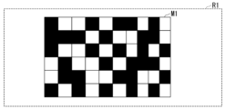
- FIG. 4 is a diagram showing an example of a binary pattern of the structured detection mask according to the first embodiment of the present invention.
- FIG. 2 is a diagram showing an example of a configuration for performing structured detection according to the first embodiment of the present invention;
- FIG. 10 is a diagram showing an example of a configuration for performing structured detection according to a modification of the first embodiment of the present invention;
- FIG. 10 is a diagram showing an example of a configuration for performing structured detection according to the second embodiment of the present invention;
- FIG. 11 is a diagram showing an example of a configuration for performing structured detection according to a modification of the second embodiment of the present invention
- FIG. 10 is a diagram showing an example of a configuration for performing structured detection according to the third embodiment of the present invention
- FIG. 12 is a diagram showing an example of a configuration for performing structured detection according to the fourth embodiment of the present invention
- FIG. 1 is a diagram showing an example of the configuration of a flow cytometer 1 according to this embodiment.
- the flow cytometer 1 comprises a microfluidic device 2, a light source 3, an illumination optics 4, an imaging optics 5, a structured detection mask 6, a photodetector 7, a DAQ device 8, and a personal computer.
- PC Personal Computer
- the flow cytometer 1 acquires light emitted from an observation target as a signal that can be converted into an image using ghost cytometry (GC) technology.
- the flow cytometer 1 acquires information derived from the shape of the object to be observed by structured detection based on GC technology.
- structured detection means a configuration in which the structured detection mask 6 is provided at a position between the flow path 20 and the photodetector 7 on the optical path from the light source 3 to the photodetector 7 .
- the microfluidic device 2 comprises a channel 20 through which the cells C1 can flow together with the fluid.
- the flow velocity of the fluid flowing through the channel 20 is constant during the measurement of the observation object.
- the microfluidic device 2 sequentially flows a plurality of cells into the channel 20, only one cell passes through the irradiation position during measurement of the object to be observed.
- a cell C1 is an example of an observation object. Note that the object to be observed is not limited to the cell C1, and may be, for example, biologically derived microparticles such as bacteria, or non-biologically derived microparticles such as plastics and beads.
- the figure shows an xyz coordinate system as a three-dimensional orthogonal coordinate system as appropriate.
- the x-axis direction is the width direction of the channel 20 .
- the y-axis direction is the length direction of the channel 20 .
- the z-axis direction is a direction orthogonal to the channel 20 and is the depth direction of the channel 20 .
- the depth direction of the channel 20 is also referred to as the height direction of the channel 20 .
- the liquid flow in channel 20 moves cell C1 in the +y direction of the y-axis.
- the width direction of the channel 20 or the depth direction of the channel 20 is, in other words, the direction perpendicular to the streamline of the fluid flowing together with the cell C1.
- the width and depth of the channel 20 can be appropriately selected depending on the object to be observed.
- the width and depth of the channel 20 can each be set to approximately 20 ⁇ m to 500 ⁇ m, but are not necessarily limited to this range.
- the width and depth of the channel 20 are equal. That is, the cross section of the flow path 20 is square.
- the width and depth of the channel 20 may be different. In other words, the cross section of the channel 20 may be rectangular. It should be noted that a flow focusing mechanism for limiting the width of the stream line through which the object to be observed passes can be added to the channel 20 .
- the light source 3 irradiates the cells C1 flowing through the channel 20 with the illumination light L1.
- the illumination light L1 from the light source 3 illuminates the cells C1 flowing through the channel 20 via the illumination optical system 4 .
- the illumination light L1 emitted by the light source 3 may be coherent light or incoherent light.
- An example of coherent light is laser light, and an example of incoherent light is light-emitting diode (LED) light.
- the illumination light L1 emitted by the light source 3 is, for example, coherent light.
- the illumination optical system 4 is a mechanism for spatially and substantially uniformly illuminating the cells C1 passing through the channel 20 .
- the illumination optical system 4 includes at least one optical element of a mirror and a lens.
- the illumination optical system 4 may further include a slit for shaping light and other optical elements.
- the optical elements constituting the illumination optical system differ depending on the light quality of the illumination light L1 emitted by the light source 3, the optical path from the light source 3 to the irradiation position of the flow path 20, and the separation method of the illumination light and the scattered light.
- the illumination optical system 4 shapes the illumination light L1 emitted by the light source 3 into the illumination light L2 having a predetermined shape at the irradiation position of the flow path 20 and irradiates the illumination light L2.
- the illumination light L2 having the predetermined shape is shown using a rectangular parallelepiped as an example.
- the illumination light L2 is preferably parallel light.
- FIG. 2 is a diagram showing an example of the shape of illumination light L2 according to this embodiment.
- FIG. 2 shows the shape of the illumination light L2 irradiated to the irradiation position of the flow path 20 when the flow path 20 shown in FIG. 1 is viewed from above.
- the shape of the illumination light L2 at the irradiation position of the channel 20 is substantially rectangular.
- the rectangle has a width direction length W1 in the width direction of the flow channel 20 and a length direction length W2 in the length direction of the flow channel 20 .
- the length direction of the channel 20 is the flow direction of the fluid flowing through the channel 20 .
- the length W2 is longer than the width W1.
- the illumination optical system 4 shapes the illumination light L1 emitted by the light source 3 into illumination light L2 having a length W2 equal to or greater than the width W1 at the irradiation position of the flow path 20. .
- the longitudinal length W2 is any length in the range from 30 ⁇ m to 2000 ⁇ m. More preferably, the longitudinal length W2 is any length in the range of 50 ⁇ m to 1000 ⁇ m.
- the range of the longitudinal length W2 the above range of 50 ⁇ m to 1000 ⁇ m is determined from a practical point of view with a lower limit and an upper limit.
- the length W2 of the illumination light L2 irradiated to the observation object is the size of the observation object (for example, the cell size CZ1) is preferably sufficiently longer than As described above, the cell size CZ1 is about 5 ⁇ m to 20 ⁇ m.
- at least the length W2 in the longitudinal direction needs to be larger than the cell size CZ1 of the cell C1, which is the object of observation, so that the cell C1 can be identified without fluorescently labeling the scattered light emitted from the cell C1.
- the length W2 in the length direction of the illumination light L2 is preferably set to a length of 50 ⁇ m or more, and more preferably set to a length of 100 ⁇ m or more. desirable.
- the longitudinal length W2 of the illumination light L2 is preferably 1000 ⁇ m or less. More preferably, the length W2 of the illumination light L2 is 500 ⁇ m or less.
- the longitudinal length W2 is desirably in the range of 50 ⁇ m to 1000 ⁇ m.
- the range of the longitudinal length W2 the above range of 30 ⁇ m to 2000 ⁇ m is determined based on the theoretical lower limit and upper limit.
- the lower limit of the longitudinal length W2 of 30 ⁇ m causes the illumination light L2 to form an image on the structured detection mask 6 as will be described later, but the lower limit of 30 ⁇ m is not sufficient for discrimination of the cell C1.
- the minimum number of pixels (for example, 70 to 80 pixels) according to the required resolution is the lower limit determined in consideration of the length that can be effectively arranged.
- the upper limit of the longitudinal length W2 of 2000 ⁇ m is an upper limit determined by the optical system provided in the imaging optical system 5 .
- the limit determined by the optical system is, for example, the size of the field of view of the objective lens.
- the widthwise length W1 is shorter than the channel width X1, which is the length of the width of the channel 20 .
- the widthwise length W1 is preferably equal to or less than the channel width X1. This is because, if the widthwise length W1 is longer than the channel width X1, the illumination light L2 is excessively irradiated to the outside of the channel 20 through which the cells C1 do not pass, and the amount of light is wasted.
- the channel width X1 is set to a size that allows the fluid containing the cells C1 to flow through the channel 20 without clogging and damaging the cells C1.
- the channel width X1 is often set in the range of 50 ⁇ m to 300 ⁇ m. As an example, when the channel width X1 is 100 ⁇ m, the widthwise length W1 is set to 100 ⁇ m or less.
- the width-direction length W1 is preferably equal to or greater than the extent of positional deviation of the streamline of the cell C1.
- the positional deviation of the streamline means that the passing position of the observation target flowing along with the fluid in the channel varies in the width direction of the channel and is not constant.
- the width-direction length W1 is greater than or equal to the positional displacement of the streamline, the cell C1 is irradiated outside the irradiation position of the illumination light L2 even when the positional displacement of the streamline of the cell C1 occurs. A large change in the intensity of the light L2 can be suppressed.
- the width-direction length W1 is preferably equal to or larger than the cell size CZ1.
- the cell size CZ1 is the size of the cell C1, which is the object of observation.
- the cell size CZ1 varies depending on the type of cell, but most of them have a size of about 5 ⁇ m to 20 ⁇ m. Since the flow cytometer 1 acquires information derived from the shape of the observation object, it is preferable that the illumination light L2 is applied to all the parts constituting the observation object. Therefore, the widthwise length W1 is preferably equal to or greater than the size of the observed object.
- the illumination light for acquiring forward scattered light (Forward Scatter: FSC) is not only for acquiring the FSC but also for exciting the fluorescent dye. It was necessary to irradiate the cells with intensity. Therefore, the illumination light had to be condensed. On the other hand, in order to suppress a large change in the intensity of the illumination light irradiating the cells even when the positional deviation of the streamline occurs, it is necessary to widen the illumination light in the width direction of the channel. Desired. Due to these demands, conventional flow cytometers irradiate illumination light broadly in the width direction of the channel and narrowly in the flow direction (streamline direction) of the channel in consideration of the positional deviation of the streamline. .
- FSC Forward Scatter
- the flow cytometer 1 acquires the scattered light from the cell C1 as a signal that can be converted into an image using GC technology by structured detection.
- the flow cytometer 1 needs to experience the pattern of the structured detection mask 6 and acquire the scattered light emitted from the cell C1 passing through the channel 20 . Therefore, in the flow cytometer 1, it is necessary to irradiate the illumination light L2 widely in the flow direction (streamline direction) of the flow channel 20.
- the channel is typically irradiated with illumination light having a width of about 100 ⁇ m in the width direction of the channel and about 10 ⁇ m in the length direction of the channel. rice field.
- the illumination light used in the conventional flow cytometer irradiates with the length of the channel in the longitudinal direction being about 1/10 of the length in the width direction of the channel.
- the ratio of the length in the length direction of the flow channel 20 to the length in the width direction of the flow channel 20 for the shape of the illumination light L2 is large compared to the illumination light.
- the length in the length direction of the channel 20 is The ratio may be any predetermined ratio greater than one tenth.
- the ratio of the longitudinal length W2 to the widthwise length W1 may be 1/5.
- the range of the length W2 in the longitudinal direction is within the range of 30 ⁇ m to 2000 ⁇ m from the theoretical requirement.
- the width W1 When changing the length W2 in the range of 30 ⁇ m to 2000 ⁇ m, the width W1 Preferably, the longitudinal length W2 and the widthwise length W1 are varied while maintaining a predetermined ratio of greater than 1/10. If the intensity of the illumination light L2 is greater than or equal to a predetermined value, the ratio of the lengthwise length W2 to the widthwise length W1 may be changed from the predetermined ratio as long as it is greater than 1/10.
- the illumination light L ⁇ b>2 shaped by the illumination optical system 4 is applied to the irradiation position in the flow path 20 .
- the cell C1 is irradiated with the illumination light L2 after passing through the irradiation position.
- the illumination light L2 is scattered by the cell C1, and the scattered light L3 is emitted from the cell C1.
- the fluorescent molecules contained in the cell C1 are excited and emit light.
- fluorescence is emitted from the cell C1.
- a component of the illumination light L2 applied to the cell C1 that has passed through the cell C1 propagates to the imaging optical system 5 as direct light L4 (also referred to as transmitted light).
- the imaging optical system 5 forms an image of the scattered light L3 emitted from the cell C1 on the structured detection mask 6.
- the imaging optical system 5 includes an imaging lens. By means of said imaging lens the scattered light L3 is collected and imaged onto a position where the structured detection mask 6 is provided. In FIG. 1, the scattered light L3 condensed by the imaging lens is shown as scattered light L5.
- the imaging optical system 5 may be either an infinite correction system or a finite correction system. A specific example of the configuration of the imaging optical system 5 will be described later.
- the structured detection mask 6 has a transmitting portion and a blocking portion.
- the transmissive portion is a region through which light is transmitted.
- a blocking part is a region that blocks light.
- methods such as absorption, reflection, refraction, and diffraction of light are used singly or in combination.
- the structured detection mask 6 has a binary pattern consisting of transmissive portions and blocking portions, and the pattern of regions through which light is transmitted is determined according to the arrangement of the transmissive portions. Only that component of the scattered light L5 that has passed through the transmissive portions of the structured detection mask 6 is detected by the photodetector 7 . In FIG. 1, the component of the scattered light L5 that has passed through the transmitting portion is shown as the scattered light L6.
- the photodetector 7 detects the scattered light L6 that has passed through the transmissive portion of the structured detection mask 6 .
- the scattered light L6 detected by the photodetector 7 may be scattered light scattered in any direction. That is, the scattered light L6 may be FSC, side scatter (SSC), or backscatter light (Backward scatter: BSC).
- FSC side scatter
- BSC backscatter light
- a case where FSC is detected as scattered light L6 will be described. That is, in the present embodiment, as an example, a case is described in which the forward scattered FSC among the scattered light emitted by the cell C1 is detected by the structured detection configuration.
- the DAQ device 8 converts the electrical signal waveform output by the photodetector 7 into electronic data for each waveform.
- Electronic data includes a combination of time and strength of electrical signals.
- DAQ device 8 is, for example, an oscilloscope.
- the PC 8 Based on the electronic data output from the DAQ device 8, the PC 8 analyzes the cell C1 and generates optical information.
- the PC 8 can also store optical information generated by itself.
- the structured detection mask 6 having a binary pattern is placed at the position where the scattered light L3 emitted from the cell C1 is imaged by the imaging optics 5.
- FIG. As a result, the scattered light L6 detected by the photodetector 7 becomes a signal convoluted with information derived from the shape of the cell C1.
- the position where the cell C1 is imaged on the structured detection mask 6 changes according to the movement of the cell C1.
- the binary pattern of the structured detection mask 6 is a random pattern, that is, when the light-transmitting regions (transmissive portions) of the structured detection mask 6 are arranged without regularity
- the cells C1 pass through the channel 20.
- the shape of the cell C1 can be estimated from time-series changes in the intensity of the scattered light L6 detected during movement.
- the propagation path of the direct light L4 and the propagation path of the scattered light L3 are spatially separated by the illumination optical system 4 and the imaging optical system 5.
- the direct light L4 is a component of the illumination light L2 shaped by the illumination optical system 4 as described above and transmitted through the cell C1. Therefore, the propagation path of the illumination light L2 formed by the illumination optical system 4 and the propagation path until the scattered light L3 emitted from the cell C1 is detected by the photodetector 7 are the illumination optical system 4 and the imaging optical system. are spatially separated by system 5.
- the scattered light L3 is detected as scattered light L6 by the photodetector 7 through the structured detection mask 6.
- FIGS. 3 to 7 a configuration for spatially separating the propagation path of the direct light L4 and the propagation path of the scattered light L3 by the illumination optical system 4 and the imaging optical system 5 will be described.
- An example of the configuration is a configuration (referred to as a first spatial separation configuration) in which the direct light L4 is blocked by an optical cutoff.
- Another example of the configuration is a configuration in which the direction of the optical axis of the imaging optical system 5 is shifted from the direction in which the direct light L4 propagates (referred to as a second spatial separation configuration) without providing an optical blocker. .
- FIG. 3 is a diagram showing the first spatial separation configuration A1 according to this embodiment.
- the first spatial separation configuration A1 is an example of a first spatial separation configuration.
- the imaging optical system 5 includes a detection lens 51 , an imaging lens 52 and an optical blocker 53 .
- the optical axis of the imaging optical system 5 is defined as an imaging optical system optical axis AX1.
- the detection lens 51, the light interrupter 53, and the imaging lens 52 are provided in this order from the flow path 20 toward the photodetector 7 on the imaging optical system optical axis AX1. That is, the detection lens 51 is provided at a position closest to the flow path 20 among the imaging lenses provided in the imaging optical system 5 .
- the imaging lens 52 is provided at a position closest to the photodetector 7 among the imaging lenses provided in the imaging optical system 5 .
- the illumination light L2 is incident on the cells C1 flowing through the channel 20 as parallel light by the illumination optical system 4 . Therefore, the propagation direction of the direct light L4 is substantially parallel to the imaging optical system optical axis AX1.
- the direct light L4 incident on the imaging optical system 5 propagates toward the photodetector 7 substantially parallel to the optical axis AX1 of the imaging optical system.
- the direct light L4 is condensed by the detection lens 51.
- the position P1 is the position where the direct light L4 is most focused by the detection lens 51 on the imaging optical system optical axis AX1.
- the position P1 is a position between the detection lens 51 and the imaging lens 52 on the imaging optical system optical axis AX1.
- the light interrupter 53 is installed at a position P1 on the imaging optical system optical axis AX1.
- the light blocker 53 blocks and does not transmit light incident on itself. That is, the light blocker 53 blocks the direct light L4 incident thereon.
- the size of the light blocker 53 is larger than the spread in the direction orthogonal to the propagation direction of the direct light L4 when the direct light L4 is incident on itself.
- the light interrupter 53 is, for example, a light blocking plate.
- the light interrupter 53 is arranged between the channel 20 and the structured detection mask 6 on the imaging optics optical axis AX1. In the first spatial separation configuration A1, the optical breaker 53 is arranged at position P1. Although it is preferable that the light interrupter 53 is arranged at the position P1 as in the example of FIG. may be placed in position.
- FIG. 4 is a diagram showing an example of the first spatial separation configuration A2 according to this embodiment.
- the first spatial separation configuration A2 is a second example of the first spatial separation configuration.
- the explanation of the first spatial separation configuration A2 the explanation will focus on the parts that are different from the first spatial separation configuration A1 (FIG. 3).
- two optical interrupters, an optical interrupter 531 and an optical interrupter 532, are provided.
- the propagation direction of the illumination light L2 is the direction of the imaging optical system optical axis AX1, but the illumination light L2 does not necessarily need to be collimated by the illumination optical system 4.
- the direct light L4 enters the imaging optical system 5 from multiple directions. Of the direct light L4 incident on the imaging optical system 5 from a plurality of directions, the light that propagates in the direction of the optical axis AX1 of the imaging optical system is blocked by the light cutoff.
- the direct light L41 and the direct light L42 are each condensed by the detection lens 51.
- the position P21 is the position where the direct light L41 is most constricted.
- the position P22 is the position where the direct light L42 is most constricted.
- the optical interrupter 531 is arranged at the position P21.
- the optical interrupter 532 is arranged at the position P22.
- the light interrupters 531 and 532 respectively block the direct light L41 and the direct light L42 propagating in the direction of the imaging optical system optical axis AX1.
- the optical interrupters 531 and 532 are preferably arranged at the positions P21 and P22, respectively, as shown in FIG. 5, but this is not the only option.
- the present invention is not limited to this.
- the number of optical breakers corresponding to the number of propagation directions of the direct light L4 may be provided.
- FIG. 5 is a diagram showing an example of the first spatial separation configuration A3 according to this embodiment.
- the first spatial separation configuration A3 is a third example of the first spatial separation configuration.
- the explanation of the first spatial separation configuration A3 the explanation will focus on the parts different from the first spatial separation configuration A1 (FIG. 3).
- the propagation direction of the illumination light L2 is the direction of the imaging optical system optical axis AX1, but the illumination light L2 is not collimated by the illumination optical system 4.
- the direct light L4 does not enter the flow path 20 and the detection lens 51 as a parallel light beam, but the light beam propagates in the direction of the imaging optical system optical axis AX1.
- the direct light L4 is condensed by the detection lens 51.
- the position P3 is the position where the direct light L4 is most constricted.
- the light interrupter 53 is arranged at a position P3 on the imaging optical system optical axis AX1.
- the light blocker 53 blocks the direct light L4 propagating in the direction of the imaging optical system optical axis AX1.
- the light blocker 53 can be arranged at another location on the imaging optical system optical axis AX1, it is preferably arranged at the position P3 where the direct light L4 is most constricted as in the example of FIG.
- FIG. 6 is a diagram showing an example of the first spatial separation configuration A4 according to this embodiment.
- the first spatial separation configuration A4 is a fourth example of the first spatial separation configuration.
- the explanation of the first spatial separation configuration A4 the explanation will focus on the parts different from the first spatial separation configuration A1 (FIG. 3).
- the propagation direction of the illumination light L2 is the direction of the imaging optical system optical axis AX1, but the illumination light L2 is not collimated by the illumination optical system 4.
- the light interrupter 53 is arranged at a position closer to the flow path 20 than the detection lens 51 on the imaging optical system optical axis AX1. That is, in the first spatial separation configuration A4, the direct light L4 propagating in the direction of the imaging optical system optical axis AX1 is blocked before entering the detection lens 51.
- the imaging optics 5 comprises a light interrupter 53 arranged between the channel 20 and the structured detection mask 6 to block the direct light L4.
- the propagation path of the illumination light (direct light L4) formed by the illumination optical system 4 and the scattered light L3 emitted from the observation target (cell C1) are detected by the photodetector 7.
- the propagation path up to is spatially separated by blocking the illumination light (direct light L4) shaped by the illumination optical system 4 with the light cutoff 53 .
- the direct light L4 becomes noise when detecting the scattered light L3 as a signal.
- the optical interrupter 53 by providing the optical interrupter 53, it is possible to spatially separate the propagation path of the direct light L4, which is noise, from the propagation path of the scattered light L3. Noise can be reduced compared to the case.
- the light blocker 53 is configured such that at least one of the illumination optical system 4 and the imaging optical system 5 narrows the illumination light (direct light L4) formed by the illumination optical system 4 to the maximum. It is preferably arranged at the above position (for example, position P1). With this configuration, more illumination light (direct light L4) is blocked than when the light blocker 53 is not arranged at one or more positions where the illumination light (direct light L4) formed by the illumination optical system 4 is most focused. Noise can be reduced because it can be cut off.
- the illumination light L2 is collimated by the illumination optical system 4 only in one axial direction (for example, the x-axis direction) in the direction perpendicular to the imaging optical system optical axis AX1. , and may be slightly narrowed by the illumination optical system 4 in the direction perpendicular to the uniaxial direction (for example, the z-axis direction) and made incident on the imaging optical system 5 .
- the illumination optical system 4 includes, for example, a cylindrical lens.
- FIG. 7 is a diagram showing an example of the second spatial separation configuration B1 according to this embodiment.
- the second spatial separation configuration B1 is an example of a second spatial separation configuration.
- the direction of the propagation path of the illumination light L2 formed by the illumination optical system 4 is defined as an illumination light propagation axis AX2.
- the direct light L4 which is the illumination light L2 that has passed through the cell C1, propagates in the direction of the illumination light propagation axis AX2.
- the direction of the illumination light propagation axis AX2 is shifted by the illumination optical system 4 to a direction different from the direction of the imaging optical system optical axis AX1.
- the imaging optical system optical axis AX1 is parallel to the y-axis, whereas the illumination light propagation axis AX2 is tilted from the y-axis toward the z-axis.
- the direct light L4 propagates in the direction of the illumination light propagation axis AX2 and propagates through the detection lens 51b in a direction in which it does not enter the photodetector .
- the imaging lens 52b images the scattered light L3, which has been made substantially parallel by the detection lens 51b, onto the structured detection mask 6.
- the direct light L4 propagating in the direction of each of the plurality of illumination light propagation axes AX2 propagates through the detection lens 51b in a direction in which it does not enter the photodetector 7. do.
- the optical breaker 53 is not provided in the second spatial separation configuration B1, unlike the first spatial separation configuration described above.
- the illumination optical system 4 is configured so that the direction of the propagation path of the illumination light L2 to be shaped (the direction of the illumination light propagation axis AX2) is the scattered light L3 emitted from the observation object (cell C1).
- the illumination light L2 is shaped so as to be in a direction different from the direction of the propagation path until it is detected by the detector 7 (the direction of the imaging optical system optical axis AX1).
- the propagation path of the illumination light L2 formed by the illumination optical system 4 and the scattered light L3 emitted from the observation object are detected by the photodetector 7 without providing a light blocker. Since the propagation path up to is spatially separated, noise can be reduced with a simple configuration.
- FIG. 8 is a diagram showing an example of the binary pattern M1 of the structured detection mask 6 according to this embodiment.
- the object to be observed the cell C1 passing through the flow path 20 is irradiated with the illumination light L2 shaped by the illumination optical system 4, and the scattered light L3 emitted from the cell C1 is focused by the imaging optical system 5. It is the illuminated area in the image plane.
- the area in which the binary pattern M1 is arranged in the structured detection mask 6 is smaller than or as large as the illuminated area R1 when compared in the object plane.
- the object plane is a plane where the cell C1 exists in the channel 20 .
- Comparing the size of the binary pattern M1 of the structured detection mask 6 and the size of the cell C1 on the object plane means that the size of the image of the binary pattern M1 of the structured detection mask 6 formed on the channel 20 and the size of the flow channel 20 are compared. It means comparing the size of the cell C1 passing through the position of the image in the path 20.
- the scattered light L3 emitted when the object to be observed is irradiated with the illumination light L2 in a wide irradiation area in the length direction (streamline direction) of the flow path 20 is converted into the binary pattern M1. Efficient detection is ensured via the included transparent portion. If the area in which the binary pattern M1 is arranged is larger than the illuminated area R1, there will be areas of the binary pattern M1 that are not illuminated by the illumination light L2, resulting in portions that are not used for structured detection.
- the size of the region in which the binary pattern M1 is arranged in the structured detection mask 6 depends on the width of the channel 20, the degree of flow focusing, the size of the observation target and the target site (internal structure to be observed) of the observation target. determined based on For example, when the object to be observed is a cell C1, the width direction size of the region where the binary pattern M1 is arranged is 300 ⁇ m on the object plane in the direction perpendicular to the flow (the width direction of the channel 20). It is preferable to set as follows. On the other hand, it is preferable to set the size of the region in which the binary pattern M1 is arranged in the flow direction (the length direction of the channel 20) to be 1500 ⁇ m or less on the object surface (the position where the cell C1 exists).
- the pattern of the binary pattern M1 is determined according to the arrangement of the transmissive portions, and the transmissive portions are configured as aggregates of a plurality of pixels.
- a pixel is the smallest unit that constitutes the transparent portion of the binary pattern M1, and the transparent portion is arranged on the binary pattern M1 in units of pixels. Since the binary pattern M1 is composed of a plurality of pixels, it is possible to divide the observed object and detect scattered light for each portion.
- the binary pattern M1 is fixed and does not change while the flow cytometer 1 is measuring.
- the transmissive portions or the blocking portions are randomly arranged on the binary pattern M1 in units of pixels.
- the binary patterns M1 can be arranged linearly instead of irregularly.
- the binary pattern M1 can consist of, for example, 2 to 1 million pixels.
- the ratio of the entire transmission area in the area where the binary pattern M1 is arranged depends on the size of the observation target (the size of the target site when the target site is a part of a cell) and the irradiation of the observation target. The optimum ratio changes depending on the intensity of the illuminated illumination light L2. The intensity of the detected light increases as the percentage of the entire transmission portion increases.
- the spatial resolution can be improved by setting the ratio of the transparent portion to 10% or less of the area where the binary pattern M1 is arranged.
- the size and shape of the pixels forming the binary pattern M1 are appropriately adjusted depending on the size of the target site included in the observation object.
- the pixel size is preferably set to be sufficiently small relative to the size of the target site.
- the number of pixels depends on the cell as the object of observation.
- the size and shape are, for example, a circle with a radius of 10 ⁇ m or less or a square with a side of 10 ⁇ m or less on the object plane.
- the size and shape of the pixel are, for example, a circle with a radius of 1 ⁇ m or less or a square with a side of 1 ⁇ m or less on the object plane.
- the diameter of the nucleus of mammalian cells is approximately 6 ⁇ m.
- the pixel shape is preferably designed as a square, rectangle, circle, or ellipse, but is not limited thereto, and may be configured in other shapes such as polygons.
- FIG. 9 is a diagram showing an example of a configuration D1 for performing structured detection according to this embodiment.
- Configuration D1 is for detecting FSC in an infinite correction system by structured detection.
- the imaging optical system 5 comprises a detection lens 51, an imaging lens 52 and a light blocker 53.
- the illumination light L2 emitted from the illumination optical system 4 is applied to the cell C1 passing through the illumination position of the channel 20. Scattered light is emitted from the cell C1 irradiated with the illumination light L2. Of the scattered light, the FSC scattered in the irradiation direction of the illumination light L2 enters the detection lens 51 as the scattered light L3. Further, the component of the illumination light L2 applied to the cell C1 that has passed through the cell C1 enters the detection lens 51 as direct light L4.
- the scattered light L3 that has passed through the detection lens 51 is incident on the imaging lens 52 as a parallel light flux at infinity.
- the scattered light L3 incident on the imaging lens 52 is imaged as scattered light L5 at the position where the structured detection mask 6 is arranged.
- Scattered light L 6 which is the FSC transmitted through structured detection mask 6 , is detected by photodetector 7 .
- the configuration D1 includes the above-described first spatial separation configuration A1 (FIG. 3) as a configuration for spatially separating the propagation path of the direct light L4 and the propagation path of the scattered light L3.
- the direct light L4 is collected by the detection lens 51 and blocked by the light blocker 53 at the most focused position.
- FIG. 10 is a diagram showing an example of a configuration D1a for performing structured detection according to a modification of this embodiment.
- the configuration other than the configuration for performing structured detection is common to the first embodiment, and configuration D1a will be described here.
- Configuration D1a is a configuration for detecting FSC in a finite correction system.
- the imaging optics 5 comprises a detection lens 51 and a light blocker 53.
- the scattered light L3 that has passed through the detection lens 51 is imaged by the detection lens 51 at a position where the structured detection mask 6 is arranged.
- the direct light L4 is collected by the detection lens 51 and blocked by the light blocker 53 at the most focused position.
- FIG. 11 is a diagram showing an example of a configuration D2 for performing structured detection according to this embodiment.
- Configuration D2 is a configuration for detecting FSC by structured detection in an infinitely corrected system and for detecting FSC detected by a conventional flow cytometer.
- the same reference numerals are given to the same configurations as those of the above-described first embodiment, and the descriptions of the same configurations and operations may be omitted.
- the imaging optics 5 comprises a detection lens 51, an imaging lens 52, a light blocker 53, a beam splitter 54, a slit 55, an imaging lens 56, and a rectangular window mask 57.
- Configuration D2 includes a photodetector 70 to detect FSC as detected by a conventional flow cytometer.
- the beam splitter 54 transmits part of the incident light and reflects the remaining part.
- the slit 55 functions as a diaphragm that adjusts the amount of incident light.
- An aperture may be provided instead of the slit 55 .
- the rectangular window mask 57 is a mask having a rectangular window through which light can pass.
- the scattered light L3 that has passed through the detection lens 51 propagates toward the imaging lens 52 as a parallel light flux at infinity.
- part of the scattered light L3 is transmitted toward the imaging lens 52 and the rest is reflected toward the imaging lens 56 by the beam splitter 54 .
- the scattered light L3 transmitted towards the imaging lens 52 is collected by the imaging lens 52 and imaged as scattered light L5 at the position where the structured detection mask 6 is arranged.
- Scattered light L 6 transmitted through structured detection mask 6 is detected by photodetector 7 .
- the scattered light L6 detected by the photodetector 7 through the structured detection mask 6 contains information derived from the shape of the observed object detected by the structure of structured detection.
- the scattered light L3 reflected toward the imaging lens 56 passes through the slit 55 and is condensed by the imaging lens 56 as scattered light L50.
- the collected scattered light L50 passes through the rectangular window mask 57 and is detected by the photodetector 70 as scattered light L60.
- Scattered light L60 detected by photodetector 70 is light detected as FSC in a conventional flow cytometer.
- FIG. 12 is a diagram showing an example of a configuration D2a for performing structured detection according to a modification of this embodiment.
- Configuration D2a is a configuration for performing bright-field light detection at the same time as FSC is detected by structured detection in an infinity correction system.
- the configuration for performing structured detection is substantially the same as that of the second embodiment, so the configuration for performing bright-field light detection will be described below.
- the imaging optical system 5 includes a detection lens 51, an imaging lens 52, a mirror 53a, and an imaging lens .
- Configuration D2a comprises a structured detection mask 61 and a photodetector 71 for brightfield light detection.
- Mirror 53a reflects direct light L4 toward photodetector 71 for brightfield light detection.
- the direct light L4 since the direct light L4 is reflected by the mirror 53a, the direct light L4 does not propagate toward the photodetector 7 as in the first spatial separation arrangement A1. That is, the mirror 53a has both a function of reflecting the direct light L4 for bright field light detection and a function of blocking the direct light L4 as in the first spatial separation configuration A1.
- the structured detection mask 61 is, like the structured detection mask 6, a mask with a binary pattern.
- the direct light L4 transmitted through the detection lens 51 is reflected toward the photodetector 71 by the mirror 53a.
- the reflected direct light L4 enters the imaging lens 56 as direct light L40.
- the direct light L40 is collected by the imaging lens 56 and imaged at the location where the structured detection mask 61 is located.
- Direct light L 41 transmitted through structured detection mask 61 is detected by photodetector 71 . Since the direct light L41 (bright field light) detected by the photodetector 71 is detected through the structured detection mask 61 by the structure of structured detection, image information obtained by bright field observation of the shape of the observation target is obtained. is included.
- FIG. 13 is a diagram showing an example of the configuration D3 for performing structured detection according to this embodiment.
- Configuration D3 is a configuration for detecting BSC by structured detection in an infinitely corrected system.
- symbol may be attached
- the illumination optical system 4 includes an irradiation lens 58, a mirror 53b, and an irradiation detection lens 59.
- the imaging optical system 5 includes an irradiation detection lens 59 , a mirror 53 b and an imaging lens 52 .
- the configuration of the illumination optical system 4 and the configuration of the imaging optical system 5 share some configurations (mirror 53b and irradiation detection lens 59).
- the irradiation lens 58 converges the illumination light L21 to the position where the mirror 53b is provided.
- the mirror 53b reflects the illumination light L21 condensed by the illumination lens 58 toward the flow path 20 as the illumination light L22.
- the reflected illumination light L ⁇ b>22 is condensed by the irradiation detection lens 59 and irradiated to the irradiation position of the flow path 20 .
- the shape of the illumination light L22 is a shape that is wide in the length direction of the flow path 20, like the illumination light L2 of each of the above-described embodiments.
- the illumination light L22 emitted from the illumination optical system 4 is applied to the cell C1 passing through the irradiation position of the channel 20. Scattered light is emitted from the cell C1 irradiated with the illumination light L2. Of the scattered light, the BSC scattered in the direction opposite to the irradiation direction of the illumination light L22 enters the irradiation detection lens 59 as the scattered light L31. Further, the component of the illumination light L22 applied to the cell C1 that has passed through the cell C1 propagates as the direct light L42.
- the scattered light L31 that has passed through the irradiation detection lens 59 enters the imaging lens 52 as a parallel light flux at infinity.
- the scattered light L31 incident on the imaging lens 52 is imaged as scattered light L5 at the position where the structured detection mask 6 is arranged.
- Scattered light L 6 which is BSC transmitted through structured detection mask 6 , is detected by photodetector 7 .
- FIG. 14 is a diagram showing an example of a configuration D4 for performing structured detection according to this embodiment.
- Configuration D4 is for detecting FSC by structured detection using a reflective objective lens in an infinity corrected system.
- symbol may be attached
- the imaging optical system 5 includes a convex mirror 510 , a reflective objective lens 512 and an imaging lens 52 .
- Convex mirror 510 is a convex shaped mirror.
- Convex mirror 510 has a back surface 511 that blocks light.
- the convex mirror 510 is arranged such that the back surface 511 faces the channel 20 side.
- the reflective objective lens 512 collects incident light with a concave mirror.
- the reflective objective lens 512 is arranged such that the mirror faces the channel 20 side.
- a reflective objective lens 512 has an aperture in the center of the mirror.
- the scattered light L3 which is the FSC emitted from the cell C1 when the cell C1 is irradiated with the illumination light L2, enters the reflective objective lens 512. Further, the component of the illumination light L2 applied to the cell C1 that has passed through the cell C1 enters the convex mirror 510 as the direct light L4 and is blocked by the back surface 511 .
- the configuration D4 has, in principle, the same configuration as the first spatial separation configuration A1 (FIG. 3) as a configuration for spatially separating the propagation path of the direct light L4 and the propagation path of the scattered light L3.
- the back surface 511 of the convex mirror 510 functions as a light interrupter.
- the rear surface 591 does not have to be placed at a position corresponding to the pupil plane.
- the illumination optical system 4 needs to irradiate the illumination light L2 with a diameter smaller than the size of the back surface 511 .
- the reflective objective lens 512 reflects the incident scattered light L3 toward the flow path 20 by means of a concave mirror, and converges the light to the position where the convex mirror 510 is arranged.
- the convex mirror 510 reflects the scattered light L3 reflected by the reflective objective lens 512 toward the reflective objective lens 512 .
- the scattered light L3 passes through the opening of the mirror of the reflective objective lens 512 and propagates toward the photodetector 7 as parallel light.
- the scattered light L3 is collected by the imaging lens 52 and imaged as scattered light L51 at the position where the structured detection mask 6 is arranged.
- Scattered light L 6 which is the FSC transmitted through structured detection mask 6 , is detected by photodetector 7 .
- configuration D4 an example in which the direct light L4 is blocked by the back surface 511 of the convex mirror 510 has been described, but the configuration is not limited to this.
- a plane mirror may be arranged on the back surface 511 to reflect the direct light L4, thereby detecting the direct light L4 at the same time as the scattered light L3 (bright-field observation configuration).
- a finite correction system or an infinite correction system may be used.
- the embodiment having the configuration of the finite correction system may be changed to the configuration of the infinite correction system by changing the configuration of the optical system.
- the embodiment having the configuration of the infinite correction system may be changed to the configuration of the finite correction system by changing the configuration of the optical system.
- each of the above-described embodiments except for the third embodiment, an example of detecting FSC as scattered light L3 by structured detection has been described, but the present invention is not limited to this.
- one or more of FSC, BSC, and SSC may be detected by structured detection.
- an example of detecting only scattered light by structured detection has been described, but the present invention is not limited to this.
- the configuration of each embodiment may be modified to detect scattered light by structured detection while simultaneously detecting FSC, as detected by a conventional flow cytometer, or direct light (bright field light detection).
- each embodiment scattered light can be detected by structured detection, and fluorescence emitted by BSCs, SSCs, or measurement objects detected by conventional flow cytometers can be detected at the same time.
- the configuration of each embodiment can be configured to detect BSC, SSC, fluorescence, or bright-field light by structured detection as in FSC, which simultaneously detects the above-described BSC, SSC, and bright field light.
- the present invention is not limited to this.
- the first spatial separation configuration A2, the first spatial separation configuration A3, the first spatial separation configuration A4, and the second Any of the two spatial separation configurations B1 may be used.
- the method of blocking the direct light L4 is not limited to blocking the direct light L4 illustrated in the first spatial separation configuration A1. .
- methods such as light absorption, reflection, refraction, and diffraction may be used.
- the flow cytometer 1 includes the microfluidic device 2, the light source 3, the illumination optical system 4, the structured detection mask 6, the imaging optical system 5, and the light source. a detector 7;
- the microfluidic device 2 comprises a channel 20 through which an object to be observed (cell C1 in this embodiment) can flow together with the fluid.
- the light source 3 irradiates illumination light L ⁇ b>1 toward an observation target (cell C ⁇ b>1 in this embodiment) flowing through the channel 20 .
- the illumination optical system 4 converts the illumination light L1 emitted by the light source 3 to the illumination light L2 whose length in the length direction of the flow channel 20 is equal to or greater than the length in the width direction of the flow channel 20 at the irradiation position of the flow channel 20. shape and irradiate.
- the structured detection mask 6 has a binary pattern of transmissive areas that transmit light and blocking areas that block light.
- the imaging optical system 5 forms an image on the structured detection mask 6 of the scattered light L3 emitted from the object to be observed (in this embodiment, the cell C1) by irradiation with the illumination light L2 shaped by the illumination optical system 4. .
- the photodetector 7 detects the scattered light L6 transmitted through the transmissive portion of the structured detection mask 6.
- the scattered light from the observation target (in this embodiment, the cell C1) moving in the channel 20 passes through the transmission portion of the structured detection mask 6. detected by the photodetector 7 via the Further, in the flow cytometer 1 according to this embodiment, the propagation path of the illumination light L2 formed by the illumination optical system 4 and the scattered light L3 emitted from the observation target (cell C1 in this embodiment) are photodetected. The propagation path to detection by the detector 7 is spatially separated by the illumination optical system 4 and the imaging optical system 5 .
- the flow cytometer 1 forms the illumination light L2 whose length in the length direction of the flow channel 20 is equal to or greater than the length in the width direction of the flow channel 20, irradiates the observation object, and observes it. Scattered light emitted from the object is detected by a photodetector 7 through a structured detection mask 6 . Therefore, it is possible to acquire information derived from the shape of the observed object with higher resolution than the information derived from the shape of the observed object acquired by the conventional flow cytometer only from the scattered light by the structured detection configuration.
- the structured detection configuration is such that the structured detection mask 6 is positioned between the flow path 20 and the photodetector 7 on the optical path from the light source 3 to the photodetector 7 . It refers to the configuration that is provided.
- the scattered light emitted from the observation object in this embodiment, the cell C1 moving in the channel 20 is detected by the structured detection mask 6 due to the structured detection configuration. is detected through the transparent portion of the observation object (in this embodiment, the cell C1) moving in the channel 20 is detected by the structured detection mask 6 due to the structured detection configuration. is detected through the transparent portion of the
- the illumination optical system 4 illuminates the illumination light L1 emitted by the light source 3 so that the ratio of the length in the length direction of the flow path 20 to the length in the width direction of the flow path 20 is 10 at the irradiation position of the flow path 20.
- SYMBOLS 1 Flow cytometer, 2... Microfluidic device, 20... Channel, 3... Light source, 4... Illumination optical system, 6... Structured detection mask, 5... Imaging optical system, 7... Photodetector, C1... Cell, L1, L2... Illumination light, L3, L6... Scattered light
Landscapes
- Chemical & Material Sciences (AREA)
- Physics & Mathematics (AREA)
- Health & Medical Sciences (AREA)
- Life Sciences & Earth Sciences (AREA)
- Analytical Chemistry (AREA)
- Biochemistry (AREA)
- General Health & Medical Sciences (AREA)
- General Physics & Mathematics (AREA)
- Immunology (AREA)
- Pathology (AREA)
- Dispersion Chemistry (AREA)
- Investigating Or Analysing Materials By Optical Means (AREA)
Priority Applications (2)
| Application Number | Priority Date | Filing Date | Title |
|---|---|---|---|
| JP2023550403A JPWO2023053679A1 (https=) | 2021-09-30 | 2022-07-20 | |
| US18/440,156 US20240183773A1 (en) | 2021-09-30 | 2024-02-13 | Flow cytometer |
Applications Claiming Priority (2)
| Application Number | Priority Date | Filing Date | Title |
|---|---|---|---|
| JP2021-161449 | 2021-09-30 | ||
| JP2021161449 | 2021-09-30 |
Related Child Applications (1)
| Application Number | Title | Priority Date | Filing Date |
|---|---|---|---|
| US18/440,156 Continuation US20240183773A1 (en) | 2021-09-30 | 2024-02-13 | Flow cytometer |
Publications (1)
| Publication Number | Publication Date |
|---|---|
| WO2023053679A1 true WO2023053679A1 (ja) | 2023-04-06 |
Family
ID=85782278
Family Applications (1)
| Application Number | Title | Priority Date | Filing Date |
|---|---|---|---|
| PCT/JP2022/028167 Ceased WO2023053679A1 (ja) | 2021-09-30 | 2022-07-20 | フローサイトメータ |
Country Status (3)
| Country | Link |
|---|---|
| US (1) | US20240183773A1 (https=) |
| JP (1) | JPWO2023053679A1 (https=) |
| WO (1) | WO2023053679A1 (https=) |
Cited By (1)
| Publication number | Priority date | Publication date | Assignee | Title |
|---|---|---|---|---|
| WO2025049015A1 (en) * | 2023-08-28 | 2025-03-06 | Beckman Coulter, Inc. | Particle shape discrimination in flow cytometry |
Citations (7)
| Publication number | Priority date | Publication date | Assignee | Title |
|---|---|---|---|---|
| US20150276589A1 (en) * | 2014-03-31 | 2015-10-01 | Redshift Systems Corporation | Motion modulation fluidic analyzer system |
| WO2016136801A1 (ja) * | 2015-02-24 | 2016-09-01 | 国立大学法人東京大学 | 動的高速高感度イメージング装置及びイメージング方法 |
| WO2017073737A1 (ja) * | 2015-10-28 | 2017-05-04 | 国立大学法人東京大学 | 分析装置 |
| JP2018509615A (ja) * | 2015-02-19 | 2018-04-05 | プレミアム ジェネティクス (ユーケー) リミテッド | 走査型赤外線測定システム |
| WO2018199080A1 (ja) * | 2017-04-28 | 2018-11-01 | シンクサイト株式会社 | イメージングフローサイトメーター |
| WO2019241443A1 (en) * | 2018-06-13 | 2019-12-19 | Thinkcyte Inc. | Methods and systems for cytometry |
| WO2021141138A1 (ja) * | 2020-01-10 | 2021-07-15 | シンクサイト株式会社 | 新規細胞表現型スクリーニング方法 |
Family Cites Families (9)
| Publication number | Priority date | Publication date | Assignee | Title |
|---|---|---|---|---|
| US6794671B2 (en) * | 2002-07-17 | 2004-09-21 | Particle Sizing Systems, Inc. | Sensors and methods for high-sensitivity optical particle counting and sizing |
| US7092078B2 (en) * | 2003-03-31 | 2006-08-15 | Nihon Kohden Corporation | Flow cytometer for classifying leukocytes and method for determining detection angle range of the same |
| JP6312602B2 (ja) * | 2011-12-29 | 2018-04-18 | アボット・ラボラトリーズAbbott Laboratories | 回折パターンを遮断するためのフローサイトメトリーシステムおよび方法 |
| WO2014151049A1 (en) * | 2013-03-15 | 2014-09-25 | Beckman Coulter, Inc. | Optics system for a flow cytometer |
| CN105579828B (zh) * | 2013-05-28 | 2020-02-14 | 克莫麦特公司 | 图像式细胞仪 |
| US9528925B2 (en) * | 2014-02-14 | 2016-12-27 | Palo Alto Research Center Incorporated | Spatial modulation of light to determine object position |
| EP3198243B1 (en) * | 2014-09-30 | 2020-07-22 | The Regents of the University of California | Imaging flow cytometer using spatial-temporal transformation |
| EP3638987B1 (en) * | 2017-06-14 | 2025-01-01 | Cytochip Inc. | Devices and methods for cell analysis |
| WO2022168467A1 (ja) * | 2021-02-04 | 2022-08-11 | 国立大学法人大阪大学 | 分光測定装置、及び分光測定方法 |
-
2022
- 2022-07-20 JP JP2023550403A patent/JPWO2023053679A1/ja active Pending
- 2022-07-20 WO PCT/JP2022/028167 patent/WO2023053679A1/ja not_active Ceased
-
2024
- 2024-02-13 US US18/440,156 patent/US20240183773A1/en not_active Abandoned
Patent Citations (7)
| Publication number | Priority date | Publication date | Assignee | Title |
|---|---|---|---|---|
| US20150276589A1 (en) * | 2014-03-31 | 2015-10-01 | Redshift Systems Corporation | Motion modulation fluidic analyzer system |
| JP2018509615A (ja) * | 2015-02-19 | 2018-04-05 | プレミアム ジェネティクス (ユーケー) リミテッド | 走査型赤外線測定システム |
| WO2016136801A1 (ja) * | 2015-02-24 | 2016-09-01 | 国立大学法人東京大学 | 動的高速高感度イメージング装置及びイメージング方法 |
| WO2017073737A1 (ja) * | 2015-10-28 | 2017-05-04 | 国立大学法人東京大学 | 分析装置 |
| WO2018199080A1 (ja) * | 2017-04-28 | 2018-11-01 | シンクサイト株式会社 | イメージングフローサイトメーター |
| WO2019241443A1 (en) * | 2018-06-13 | 2019-12-19 | Thinkcyte Inc. | Methods and systems for cytometry |
| WO2021141138A1 (ja) * | 2020-01-10 | 2021-07-15 | シンクサイト株式会社 | 新規細胞表現型スクリーニング方法 |
Cited By (1)
| Publication number | Priority date | Publication date | Assignee | Title |
|---|---|---|---|---|
| WO2025049015A1 (en) * | 2023-08-28 | 2025-03-06 | Beckman Coulter, Inc. | Particle shape discrimination in flow cytometry |
Also Published As
| Publication number | Publication date |
|---|---|
| US20240183773A1 (en) | 2024-06-06 |
| JPWO2023053679A1 (https=) | 2023-04-06 |
Similar Documents
| Publication | Publication Date | Title |
|---|---|---|
| US10921234B2 (en) | Image forming cytometer | |
| JP6215454B2 (ja) | イメージフローサイトメーター、システム及び方法 | |
| US4999513A (en) | Particle measuring apparatus | |
| US20200103406A1 (en) | Image analysis and measurement of biological samples | |
| US7715006B2 (en) | Optical system for a particle analyzer and particle analyzer using same | |
| JP7656837B2 (ja) | フローサイトメーター | |
| US12298221B2 (en) | Observation device | |
| US20060221325A1 (en) | Flow cytometer for differentiating small particles in suspension | |
| JP2013545127A (ja) | 光学測定方法および光学測定装置 | |
| JP5824038B2 (ja) | ルミネセンスベースセンサシステム | |
| CN116046649A (zh) | 一种基于流体动力聚焦的成像系统 | |
| US20250341712A1 (en) | Apparatuses, systems and methods for solid immersion meniscus lenses | |
| WO2023053679A1 (ja) | フローサイトメータ | |
| CN111855544A (zh) | 一种荧光成像装置及其成像方法 | |
| US20230266229A1 (en) | Flow cytometer, cell sorter, optical information generation method, and program | |
| JPH08128944A (ja) | 粒子分類装置 | |
| EP4019947A1 (en) | Optical measurement device and information processing system | |
| US20050225764A1 (en) | Device and method for detecting fluorescence comprising a light emitting diode as excitation source | |
| JP3144687B2 (ja) | 粒子測定装置 | |
| KR20200027251A (ko) | 혈구 분석 장치, 이를 이용한 혈구 분석 방법 | |
| JPH0274845A (ja) | 粒子測定装置 | |
| WO2022239596A1 (ja) | 特徴量算出装置、特徴量算出方法、及びプログラム | |
| WO2024157903A1 (ja) | フローサイトメータ | |
| JPS63255643A (ja) | 粒子解析装置 |
Legal Events
| Date | Code | Title | Description |
|---|---|---|---|
| 121 | Ep: the epo has been informed by wipo that ep was designated in this application |
Ref document number: 22875557 Country of ref document: EP Kind code of ref document: A1 |
|
| WWE | Wipo information: entry into national phase |
Ref document number: 2023550403 Country of ref document: JP |
|
| NENP | Non-entry into the national phase |
Ref country code: DE |
|
| 122 | Ep: pct application non-entry in european phase |
Ref document number: 22875557 Country of ref document: EP Kind code of ref document: A1 |