WO2023053679A1 - Flow cytometer - Google Patents
Flow cytometer Download PDFInfo
- Publication number
- WO2023053679A1 WO2023053679A1 PCT/JP2022/028167 JP2022028167W WO2023053679A1 WO 2023053679 A1 WO2023053679 A1 WO 2023053679A1 JP 2022028167 W JP2022028167 W JP 2022028167W WO 2023053679 A1 WO2023053679 A1 WO 2023053679A1
- Authority
- WO
- WIPO (PCT)
- Prior art keywords
- light
- optical system
- illumination
- flow
- illumination light
- Prior art date
Links
- 238000005286 illumination Methods 0.000 claims abstract description 234
- 230000003287 optical effect Effects 0.000 claims abstract description 201
- 238000001514 detection method Methods 0.000 claims abstract description 158
- 230000000903 blocking effect Effects 0.000 claims abstract description 21
- 230000005540 biological transmission Effects 0.000 claims abstract description 9
- 238000003384 imaging method Methods 0.000 claims description 105
- 239000012530 fluid Substances 0.000 claims description 11
- 210000004027 cell Anatomy 0.000 description 107
- 238000000926 separation method Methods 0.000 description 66
- 238000010586 diagram Methods 0.000 description 24
- 238000012937 correction Methods 0.000 description 11
- 238000005516 engineering process Methods 0.000 description 8
- 238000000034 method Methods 0.000 description 8
- 238000000684 flow cytometry Methods 0.000 description 7
- 230000004048 modification Effects 0.000 description 7
- 238000012986 modification Methods 0.000 description 7
- 230000006870 function Effects 0.000 description 4
- 238000005259 measurement Methods 0.000 description 4
- 230000001902 propagating effect Effects 0.000 description 4
- 230000008859 change Effects 0.000 description 3
- 230000001427 coherent effect Effects 0.000 description 3
- 238000004163 cytometry Methods 0.000 description 3
- 238000006073 displacement reaction Methods 0.000 description 3
- 230000004907 flux Effects 0.000 description 3
- 238000002372 labelling Methods 0.000 description 3
- 210000004962 mammalian cell Anatomy 0.000 description 3
- 238000013461 design Methods 0.000 description 2
- 239000003814 drug Substances 0.000 description 2
- 230000007246 mechanism Effects 0.000 description 2
- 239000011859 microparticle Substances 0.000 description 2
- 230000001172 regenerating effect Effects 0.000 description 2
- CIWBSHSKHKDKBQ-JLAZNSOCSA-N Ascorbic acid Chemical compound OC[C@H](O)[C@H]1OC(=O)C(O)=C1O CIWBSHSKHKDKBQ-JLAZNSOCSA-N 0.000 description 1
- 241000894006 Bacteria Species 0.000 description 1
- 238000011357 CAR T-cell therapy Methods 0.000 description 1
- 240000007594 Oryza sativa Species 0.000 description 1
- 235000007164 Oryza sativa Nutrition 0.000 description 1
- 210000001744 T-lymphocyte Anatomy 0.000 description 1
- 238000010521 absorption reaction Methods 0.000 description 1
- 239000011324 bead Substances 0.000 description 1
- 238000002619 cancer immunotherapy Methods 0.000 description 1
- 238000002659 cell therapy Methods 0.000 description 1
- 238000010276 construction Methods 0.000 description 1
- 230000008878 coupling Effects 0.000 description 1
- 238000010168 coupling process Methods 0.000 description 1
- 238000005859 coupling reaction Methods 0.000 description 1
- 230000007423 decrease Effects 0.000 description 1
- 238000007876 drug discovery Methods 0.000 description 1
- 238000001917 fluorescence detection Methods 0.000 description 1
- 239000007850 fluorescent dye Substances 0.000 description 1
- 238000001215 fluorescent labelling Methods 0.000 description 1
- 210000004263 induced pluripotent stem cell Anatomy 0.000 description 1
- 230000001678 irradiating effect Effects 0.000 description 1
- 230000031700 light absorption Effects 0.000 description 1
- 239000007788 liquid Substances 0.000 description 1
- 238000010801 machine learning Methods 0.000 description 1
- 239000003550 marker Substances 0.000 description 1
- 229920003023 plastic Polymers 0.000 description 1
- 239000004033 plastic Substances 0.000 description 1
- 210000001747 pupil Anatomy 0.000 description 1
- 235000009566 rice Nutrition 0.000 description 1
- 238000007493 shaping process Methods 0.000 description 1
- 210000000130 stem cell Anatomy 0.000 description 1
- 238000002054 transplantation Methods 0.000 description 1
Images


Classifications
-
- G—PHYSICS
- G01—MEASURING; TESTING
- G01N—INVESTIGATING OR ANALYSING MATERIALS BY DETERMINING THEIR CHEMICAL OR PHYSICAL PROPERTIES
- G01N15/00—Investigating characteristics of particles; Investigating permeability, pore-volume, or surface-area of porous materials
- G01N15/10—Investigating individual particles
- G01N15/14—Electro-optical investigation, e.g. flow cytometers
-
- G—PHYSICS
- G01—MEASURING; TESTING
- G01N—INVESTIGATING OR ANALYSING MATERIALS BY DETERMINING THEIR CHEMICAL OR PHYSICAL PROPERTIES
- G01N21/00—Investigating or analysing materials by the use of optical means, i.e. using sub-millimetre waves, infrared, visible or ultraviolet light
- G01N21/17—Systems in which incident light is modified in accordance with the properties of the material investigated
- G01N21/47—Scattering, i.e. diffuse reflection
- G01N21/49—Scattering, i.e. diffuse reflection within a body or fluid
- G01N21/53—Scattering, i.e. diffuse reflection within a body or fluid within a flowing fluid, e.g. smoke
-
- G—PHYSICS
- G01—MEASURING; TESTING
- G01N—INVESTIGATING OR ANALYSING MATERIALS BY DETERMINING THEIR CHEMICAL OR PHYSICAL PROPERTIES
- G01N37/00—Details not covered by any other group of this subclass
Definitions
- the present invention relates to flow cytometers. This application claims priority based on Japanese Patent Application No. 2021-161449 filed in Japan on September 30, 2021, the contents of which are incorporated herein.
- Flow cytometry is a technique for optically analyzing cells by acquiring scattered light and fluorescence when cells are irradiated with specific light while flowing cells along a channel at a constant flow rate.
- Scattered light includes forward scattered light (FSC), side scattered light (SSC), and backscattered light (backward scatter: BSC) depending on the scattering direction.
- JP 2008-032659 A Japanese Patent Application Laid-Open No. 09-079969 WO2017/073737 WO2019/241443
- the scattered light (FSC, SSC, BSC) obtained in general flow cytometry lacks most of the information derived from the cell shape, and only the information obtained from the scattered light without any labeling is used. It is difficult to discriminate, or to discriminate and sort cells in a cell.
- ghost Cytometry (GC) technology is known as a technology that can obtain more abundant and detailed information derived from the shape of cells compared to conventional flow cytometry (Patent Documents 3 and 4. , Non-Patent Document 1).
- the scattered light emitted from an object to be observed passes through a spatial modulator, such as a structural mask pattern, in the optical path between the flow path through which the object to be observed flows and the detector.
- a spatial modulator such as a structural mask pattern
- the configuration of the illumination optical system that irradiates the observation target passing through the channel can be simplified, so the degree of freedom in device design increases. There is a need to obtain high-resolution information derived from the shape of cells, which cannot be obtained by general flow cytometry, only from scattered light by means of structured detection.
- the present invention has been made in view of the above points, and provides a flow cytometer that can acquire high-resolution information derived from the shape of an observation target only from scattered light by means of structured detection.
- One aspect of the present disclosure is a microfluidic device including a channel in which an observation target can flow together with a fluid, a light source that irradiates illumination light toward the observation target that flows through the channel, and the an illumination optical system that shapes and irradiates illumination light into illumination light whose length in the length direction of the flow channel is equal to or greater than the length in the width direction of the flow channel at the irradiation position of the flow channel; a structured detection mask having a binary pattern of transmitting portions for transmitting light and blocking portions for blocking light; an imaging optical system for forming an image on the structured detection mask; and a photodetector for detecting scattered light transmitted through the transmission portion of the structured detection mask, wherein the illumination optical system shapes the The propagation path of the direct light that has passed through the observation target object out of the illumination light and the propagation path until the scattered light emitted from the observation target object is detected by the photodetector are defined by the illumination optical system and the coupling.
- One aspect of the present disclosure is a microfluidic device including a channel in which an observation target can flow together with a fluid, a light source that irradiates illumination light toward the observation target that flows through the channel, and the Illumination light is shaped into illumination light in which the ratio of the length in the length direction of the flow channel to the length in the width direction of the flow channel is greater than 1/10 at the irradiation position of the flow channel and irradiated.
- an illumination optical system a structured detection mask having a binary pattern of a transmission portion that transmits light and a blocking portion that blocks light; an imaging optical system that forms an image of the scattered light emitted from the structured detection mask on the structured detection mask; and a photodetector that detects the scattered light transmitted through the transmission portion of the structured detection mask, The propagation path of the direct light transmitted through the observation object among the illumination light shaped by the illumination optical system and the propagation path until the scattered light emitted from the observation object is detected by the photodetector , a flow cytometer spatially separated by said illumination optics and said imaging optics;
- the lower limit of the length in the length direction of the flow path of the illumination light formed by the illumination optical system is 30 micrometers or more
- the upper limit of the length in the longitudinal direction of the channel is 2000 micrometers or less.
- the lower limit of the length in the length direction of the flow path of the illumination light formed by the illumination optical system is 50 micrometers or more.
- the upper limit of the length in the length direction of the flow path of the illumination light formed by the illumination optical system is 1000 micrometers or less.
- the upper limit of the length of the illumination light formed by the illumination optical system in the width direction of the flow path is equal to or less than the width of the flow path.
- the lower limit of the length of the illumination light formed by the illumination optical system in the width direction of the flow path is the observation object flowing through the flow path. is greater than or equal to the displacement of the streamlines in the width direction of the flow path.
- the size of the region in which the binary pattern is arranged in the structured detection mask is 300 ⁇ m or less in the width direction and 1500 ⁇ m in the flow direction on the object surface.
- the binary pattern is formed by a plurality of pixels each having a circle with a radius of 10 ⁇ m or less or a square with a side of 10 ⁇ m or less on the object plane.
- the imaging optical system further includes a light blocker disposed between the channel and the structured detection mask to block light. , a propagation path of the direct light transmitted through the observation object among the illumination light shaped by the illumination optical system, and a propagation path until scattered light emitted from the observation object is detected by the photodetector; Paths are spatially separated by the light isolator blocking the direct light.
- the light blocker causes at least one of the illumination optical system and the imaging optical system to block the direct light shaped by the illumination optical system. It is placed at one or more positions where it is most squeezed.
- the illumination optical system is arranged such that the direction of the propagation path of direct light transmitted through the observation object, out of the illumination light to be shaped, is from the observation object.
- the illumination light is shaped such that the emitted scattered light is in a direction different from the direction of the propagation path until it is detected by the photodetector.
- the region in which the binary pattern is arranged in the structured detection mask is formed by the illumination light shaped by the illumination optical system. is smaller than the illuminated area in the image plane of .
- information derived from the shape of a high-resolution observation object can be obtained only from scattered light by means of structured detection.
- FIG. 5B is a diagram showing a second example of the first spatial separation configuration according to the first embodiment of the present invention
- FIG. 10 is a diagram showing a third example of the first spatial separation configuration according to the first embodiment of the present invention.
- FIG. 10 is a diagram showing a fourth example of the first spatial separation configuration according to the first embodiment of the present invention. It is a figure which shows an example of the 2nd spatial separation structure based on the modification of the 1st Embodiment of this invention.
- FIG. 4 is a diagram showing an example of a binary pattern of the structured detection mask according to the first embodiment of the present invention.
- FIG. 2 is a diagram showing an example of a configuration for performing structured detection according to the first embodiment of the present invention;
- FIG. 10 is a diagram showing an example of a configuration for performing structured detection according to a modification of the first embodiment of the present invention;
- FIG. 10 is a diagram showing an example of a configuration for performing structured detection according to the second embodiment of the present invention;
- FIG. 11 is a diagram showing an example of a configuration for performing structured detection according to a modification of the second embodiment of the present invention
- FIG. 10 is a diagram showing an example of a configuration for performing structured detection according to the third embodiment of the present invention
- FIG. 12 is a diagram showing an example of a configuration for performing structured detection according to the fourth embodiment of the present invention
- FIG. 1 is a diagram showing an example of the configuration of a flow cytometer 1 according to this embodiment.
- the flow cytometer 1 comprises a microfluidic device 2, a light source 3, an illumination optics 4, an imaging optics 5, a structured detection mask 6, a photodetector 7, a DAQ device 8, and a personal computer.
- PC Personal Computer
- the flow cytometer 1 acquires light emitted from an observation target as a signal that can be converted into an image using ghost cytometry (GC) technology.
- the flow cytometer 1 acquires information derived from the shape of the object to be observed by structured detection based on GC technology.
- structured detection means a configuration in which the structured detection mask 6 is provided at a position between the flow path 20 and the photodetector 7 on the optical path from the light source 3 to the photodetector 7 .
- the microfluidic device 2 comprises a channel 20 through which the cells C1 can flow together with the fluid.
- the flow velocity of the fluid flowing through the channel 20 is constant during the measurement of the observation object.
- the microfluidic device 2 sequentially flows a plurality of cells into the channel 20, only one cell passes through the irradiation position during measurement of the object to be observed.
- a cell C1 is an example of an observation object. Note that the object to be observed is not limited to the cell C1, and may be, for example, biologically derived microparticles such as bacteria, or non-biologically derived microparticles such as plastics and beads.
- the figure shows an xyz coordinate system as a three-dimensional orthogonal coordinate system as appropriate.
- the x-axis direction is the width direction of the channel 20 .
- the y-axis direction is the length direction of the channel 20 .
- the z-axis direction is a direction orthogonal to the channel 20 and is the depth direction of the channel 20 .
- the depth direction of the channel 20 is also referred to as the height direction of the channel 20 .
- the liquid flow in channel 20 moves cell C1 in the +y direction of the y-axis.
- the width direction of the channel 20 or the depth direction of the channel 20 is, in other words, the direction perpendicular to the streamline of the fluid flowing together with the cell C1.
- the width and depth of the channel 20 can be appropriately selected depending on the object to be observed.
- the width and depth of the channel 20 can each be set to approximately 20 ⁇ m to 500 ⁇ m, but are not necessarily limited to this range.
- the width and depth of the channel 20 are equal. That is, the cross section of the flow path 20 is square.
- the width and depth of the channel 20 may be different. In other words, the cross section of the channel 20 may be rectangular. It should be noted that a flow focusing mechanism for limiting the width of the stream line through which the object to be observed passes can be added to the channel 20 .
- the light source 3 irradiates the cells C1 flowing through the channel 20 with the illumination light L1.
- the illumination light L1 from the light source 3 illuminates the cells C1 flowing through the channel 20 via the illumination optical system 4 .
- the illumination light L1 emitted by the light source 3 may be coherent light or incoherent light.
- An example of coherent light is laser light, and an example of incoherent light is light-emitting diode (LED) light.
- the illumination light L1 emitted by the light source 3 is, for example, coherent light.
- the illumination optical system 4 is a mechanism for spatially and substantially uniformly illuminating the cells C1 passing through the channel 20 .
- the illumination optical system 4 includes at least one optical element of a mirror and a lens.
- the illumination optical system 4 may further include a slit for shaping light and other optical elements.
- the optical elements constituting the illumination optical system differ depending on the light quality of the illumination light L1 emitted by the light source 3, the optical path from the light source 3 to the irradiation position of the flow path 20, and the separation method of the illumination light and the scattered light.
- the illumination optical system 4 shapes the illumination light L1 emitted by the light source 3 into the illumination light L2 having a predetermined shape at the irradiation position of the flow path 20 and irradiates the illumination light L2.
- the illumination light L2 having the predetermined shape is shown using a rectangular parallelepiped as an example.
- the illumination light L2 is preferably parallel light.
- FIG. 2 is a diagram showing an example of the shape of illumination light L2 according to this embodiment.
- FIG. 2 shows the shape of the illumination light L2 irradiated to the irradiation position of the flow path 20 when the flow path 20 shown in FIG. 1 is viewed from above.
- the shape of the illumination light L2 at the irradiation position of the channel 20 is substantially rectangular.
- the rectangle has a width direction length W1 in the width direction of the flow channel 20 and a length direction length W2 in the length direction of the flow channel 20 .
- the length direction of the channel 20 is the flow direction of the fluid flowing through the channel 20 .
- the length W2 is longer than the width W1.
- the illumination optical system 4 shapes the illumination light L1 emitted by the light source 3 into illumination light L2 having a length W2 equal to or greater than the width W1 at the irradiation position of the flow path 20. .
- the longitudinal length W2 is any length in the range from 30 ⁇ m to 2000 ⁇ m. More preferably, the longitudinal length W2 is any length in the range of 50 ⁇ m to 1000 ⁇ m.
- the range of the longitudinal length W2 the above range of 50 ⁇ m to 1000 ⁇ m is determined from a practical point of view with a lower limit and an upper limit.
- the length W2 of the illumination light L2 irradiated to the observation object is the size of the observation object (for example, the cell size CZ1) is preferably sufficiently longer than As described above, the cell size CZ1 is about 5 ⁇ m to 20 ⁇ m.
- at least the length W2 in the longitudinal direction needs to be larger than the cell size CZ1 of the cell C1, which is the object of observation, so that the cell C1 can be identified without fluorescently labeling the scattered light emitted from the cell C1.
- the length W2 in the length direction of the illumination light L2 is preferably set to a length of 50 ⁇ m or more, and more preferably set to a length of 100 ⁇ m or more. desirable.
- the longitudinal length W2 of the illumination light L2 is preferably 1000 ⁇ m or less. More preferably, the length W2 of the illumination light L2 is 500 ⁇ m or less.
- the longitudinal length W2 is desirably in the range of 50 ⁇ m to 1000 ⁇ m.
- the range of the longitudinal length W2 the above range of 30 ⁇ m to 2000 ⁇ m is determined based on the theoretical lower limit and upper limit.
- the lower limit of the longitudinal length W2 of 30 ⁇ m causes the illumination light L2 to form an image on the structured detection mask 6 as will be described later, but the lower limit of 30 ⁇ m is not sufficient for discrimination of the cell C1.
- the minimum number of pixels (for example, 70 to 80 pixels) according to the required resolution is the lower limit determined in consideration of the length that can be effectively arranged.
- the upper limit of the longitudinal length W2 of 2000 ⁇ m is an upper limit determined by the optical system provided in the imaging optical system 5 .
- the limit determined by the optical system is, for example, the size of the field of view of the objective lens.
- the widthwise length W1 is shorter than the channel width X1, which is the length of the width of the channel 20 .
- the widthwise length W1 is preferably equal to or less than the channel width X1. This is because, if the widthwise length W1 is longer than the channel width X1, the illumination light L2 is excessively irradiated to the outside of the channel 20 through which the cells C1 do not pass, and the amount of light is wasted.
- the channel width X1 is set to a size that allows the fluid containing the cells C1 to flow through the channel 20 without clogging and damaging the cells C1.
- the channel width X1 is often set in the range of 50 ⁇ m to 300 ⁇ m. As an example, when the channel width X1 is 100 ⁇ m, the widthwise length W1 is set to 100 ⁇ m or less.
- the width-direction length W1 is preferably equal to or greater than the extent of positional deviation of the streamline of the cell C1.
- the positional deviation of the streamline means that the passing position of the observation target flowing along with the fluid in the channel varies in the width direction of the channel and is not constant.
- the width-direction length W1 is greater than or equal to the positional displacement of the streamline, the cell C1 is irradiated outside the irradiation position of the illumination light L2 even when the positional displacement of the streamline of the cell C1 occurs. A large change in the intensity of the light L2 can be suppressed.
- the width-direction length W1 is preferably equal to or larger than the cell size CZ1.
- the cell size CZ1 is the size of the cell C1, which is the object of observation.
- the cell size CZ1 varies depending on the type of cell, but most of them have a size of about 5 ⁇ m to 20 ⁇ m. Since the flow cytometer 1 acquires information derived from the shape of the observation object, it is preferable that the illumination light L2 is applied to all the parts constituting the observation object. Therefore, the widthwise length W1 is preferably equal to or greater than the size of the observed object.
- the illumination light for acquiring forward scattered light (Forward Scatter: FSC) is not only for acquiring the FSC but also for exciting the fluorescent dye. It was necessary to irradiate the cells with intensity. Therefore, the illumination light had to be condensed. On the other hand, in order to suppress a large change in the intensity of the illumination light irradiating the cells even when the positional deviation of the streamline occurs, it is necessary to widen the illumination light in the width direction of the channel. Desired. Due to these demands, conventional flow cytometers irradiate illumination light broadly in the width direction of the channel and narrowly in the flow direction (streamline direction) of the channel in consideration of the positional deviation of the streamline. .
- FSC Forward Scatter
- the flow cytometer 1 acquires the scattered light from the cell C1 as a signal that can be converted into an image using GC technology by structured detection.
- the flow cytometer 1 needs to experience the pattern of the structured detection mask 6 and acquire the scattered light emitted from the cell C1 passing through the channel 20 . Therefore, in the flow cytometer 1, it is necessary to irradiate the illumination light L2 widely in the flow direction (streamline direction) of the flow channel 20.
- the channel is typically irradiated with illumination light having a width of about 100 ⁇ m in the width direction of the channel and about 10 ⁇ m in the length direction of the channel. rice field.
- the illumination light used in the conventional flow cytometer irradiates with the length of the channel in the longitudinal direction being about 1/10 of the length in the width direction of the channel.
- the ratio of the length in the length direction of the flow channel 20 to the length in the width direction of the flow channel 20 for the shape of the illumination light L2 is large compared to the illumination light.
- the length in the length direction of the channel 20 is The ratio may be any predetermined ratio greater than one tenth.
- the ratio of the longitudinal length W2 to the widthwise length W1 may be 1/5.
- the range of the length W2 in the longitudinal direction is within the range of 30 ⁇ m to 2000 ⁇ m from the theoretical requirement.
- the width W1 When changing the length W2 in the range of 30 ⁇ m to 2000 ⁇ m, the width W1 Preferably, the longitudinal length W2 and the widthwise length W1 are varied while maintaining a predetermined ratio of greater than 1/10. If the intensity of the illumination light L2 is greater than or equal to a predetermined value, the ratio of the lengthwise length W2 to the widthwise length W1 may be changed from the predetermined ratio as long as it is greater than 1/10.
- the illumination light L ⁇ b>2 shaped by the illumination optical system 4 is applied to the irradiation position in the flow path 20 .
- the cell C1 is irradiated with the illumination light L2 after passing through the irradiation position.
- the illumination light L2 is scattered by the cell C1, and the scattered light L3 is emitted from the cell C1.
- the fluorescent molecules contained in the cell C1 are excited and emit light.
- fluorescence is emitted from the cell C1.
- a component of the illumination light L2 applied to the cell C1 that has passed through the cell C1 propagates to the imaging optical system 5 as direct light L4 (also referred to as transmitted light).
- the imaging optical system 5 forms an image of the scattered light L3 emitted from the cell C1 on the structured detection mask 6.
- the imaging optical system 5 includes an imaging lens. By means of said imaging lens the scattered light L3 is collected and imaged onto a position where the structured detection mask 6 is provided. In FIG. 1, the scattered light L3 condensed by the imaging lens is shown as scattered light L5.
- the imaging optical system 5 may be either an infinite correction system or a finite correction system. A specific example of the configuration of the imaging optical system 5 will be described later.
- the structured detection mask 6 has a transmitting portion and a blocking portion.
- the transmissive portion is a region through which light is transmitted.
- a blocking part is a region that blocks light.
- methods such as absorption, reflection, refraction, and diffraction of light are used singly or in combination.
- the structured detection mask 6 has a binary pattern consisting of transmissive portions and blocking portions, and the pattern of regions through which light is transmitted is determined according to the arrangement of the transmissive portions. Only that component of the scattered light L5 that has passed through the transmissive portions of the structured detection mask 6 is detected by the photodetector 7 . In FIG. 1, the component of the scattered light L5 that has passed through the transmitting portion is shown as the scattered light L6.
- the photodetector 7 detects the scattered light L6 that has passed through the transmissive portion of the structured detection mask 6 .
- the scattered light L6 detected by the photodetector 7 may be scattered light scattered in any direction. That is, the scattered light L6 may be FSC, side scatter (SSC), or backscatter light (Backward scatter: BSC).
- FSC side scatter
- BSC backscatter light
- a case where FSC is detected as scattered light L6 will be described. That is, in the present embodiment, as an example, a case is described in which the forward scattered FSC among the scattered light emitted by the cell C1 is detected by the structured detection configuration.
- the DAQ device 8 converts the electrical signal waveform output by the photodetector 7 into electronic data for each waveform.
- Electronic data includes a combination of time and strength of electrical signals.
- DAQ device 8 is, for example, an oscilloscope.
- the PC 8 Based on the electronic data output from the DAQ device 8, the PC 8 analyzes the cell C1 and generates optical information.
- the PC 8 can also store optical information generated by itself.
- the structured detection mask 6 having a binary pattern is placed at the position where the scattered light L3 emitted from the cell C1 is imaged by the imaging optics 5.
- FIG. As a result, the scattered light L6 detected by the photodetector 7 becomes a signal convoluted with information derived from the shape of the cell C1.
- the position where the cell C1 is imaged on the structured detection mask 6 changes according to the movement of the cell C1.
- the binary pattern of the structured detection mask 6 is a random pattern, that is, when the light-transmitting regions (transmissive portions) of the structured detection mask 6 are arranged without regularity
- the cells C1 pass through the channel 20.
- the shape of the cell C1 can be estimated from time-series changes in the intensity of the scattered light L6 detected during movement.
- the propagation path of the direct light L4 and the propagation path of the scattered light L3 are spatially separated by the illumination optical system 4 and the imaging optical system 5.
- the direct light L4 is a component of the illumination light L2 shaped by the illumination optical system 4 as described above and transmitted through the cell C1. Therefore, the propagation path of the illumination light L2 formed by the illumination optical system 4 and the propagation path until the scattered light L3 emitted from the cell C1 is detected by the photodetector 7 are the illumination optical system 4 and the imaging optical system. are spatially separated by system 5.
- the scattered light L3 is detected as scattered light L6 by the photodetector 7 through the structured detection mask 6.
- FIGS. 3 to 7 a configuration for spatially separating the propagation path of the direct light L4 and the propagation path of the scattered light L3 by the illumination optical system 4 and the imaging optical system 5 will be described.
- An example of the configuration is a configuration (referred to as a first spatial separation configuration) in which the direct light L4 is blocked by an optical cutoff.
- Another example of the configuration is a configuration in which the direction of the optical axis of the imaging optical system 5 is shifted from the direction in which the direct light L4 propagates (referred to as a second spatial separation configuration) without providing an optical blocker. .
- FIG. 3 is a diagram showing the first spatial separation configuration A1 according to this embodiment.
- the first spatial separation configuration A1 is an example of a first spatial separation configuration.
- the imaging optical system 5 includes a detection lens 51 , an imaging lens 52 and an optical blocker 53 .
- the optical axis of the imaging optical system 5 is defined as an imaging optical system optical axis AX1.
- the detection lens 51, the light interrupter 53, and the imaging lens 52 are provided in this order from the flow path 20 toward the photodetector 7 on the imaging optical system optical axis AX1. That is, the detection lens 51 is provided at a position closest to the flow path 20 among the imaging lenses provided in the imaging optical system 5 .
- the imaging lens 52 is provided at a position closest to the photodetector 7 among the imaging lenses provided in the imaging optical system 5 .
- the illumination light L2 is incident on the cells C1 flowing through the channel 20 as parallel light by the illumination optical system 4 . Therefore, the propagation direction of the direct light L4 is substantially parallel to the imaging optical system optical axis AX1.
- the direct light L4 incident on the imaging optical system 5 propagates toward the photodetector 7 substantially parallel to the optical axis AX1 of the imaging optical system.
- the direct light L4 is condensed by the detection lens 51.
- the position P1 is the position where the direct light L4 is most focused by the detection lens 51 on the imaging optical system optical axis AX1.
- the position P1 is a position between the detection lens 51 and the imaging lens 52 on the imaging optical system optical axis AX1.
- the light interrupter 53 is installed at a position P1 on the imaging optical system optical axis AX1.
- the light blocker 53 blocks and does not transmit light incident on itself. That is, the light blocker 53 blocks the direct light L4 incident thereon.
- the size of the light blocker 53 is larger than the spread in the direction orthogonal to the propagation direction of the direct light L4 when the direct light L4 is incident on itself.
- the light interrupter 53 is, for example, a light blocking plate.
- the light interrupter 53 is arranged between the channel 20 and the structured detection mask 6 on the imaging optics optical axis AX1. In the first spatial separation configuration A1, the optical breaker 53 is arranged at position P1. Although it is preferable that the light interrupter 53 is arranged at the position P1 as in the example of FIG. may be placed in position.
- FIG. 4 is a diagram showing an example of the first spatial separation configuration A2 according to this embodiment.
- the first spatial separation configuration A2 is a second example of the first spatial separation configuration.
- the explanation of the first spatial separation configuration A2 the explanation will focus on the parts that are different from the first spatial separation configuration A1 (FIG. 3).
- two optical interrupters, an optical interrupter 531 and an optical interrupter 532, are provided.
- the propagation direction of the illumination light L2 is the direction of the imaging optical system optical axis AX1, but the illumination light L2 does not necessarily need to be collimated by the illumination optical system 4.
- the direct light L4 enters the imaging optical system 5 from multiple directions. Of the direct light L4 incident on the imaging optical system 5 from a plurality of directions, the light that propagates in the direction of the optical axis AX1 of the imaging optical system is blocked by the light cutoff.
- the direct light L41 and the direct light L42 are each condensed by the detection lens 51.
- the position P21 is the position where the direct light L41 is most constricted.
- the position P22 is the position where the direct light L42 is most constricted.
- the optical interrupter 531 is arranged at the position P21.
- the optical interrupter 532 is arranged at the position P22.
- the light interrupters 531 and 532 respectively block the direct light L41 and the direct light L42 propagating in the direction of the imaging optical system optical axis AX1.
- the optical interrupters 531 and 532 are preferably arranged at the positions P21 and P22, respectively, as shown in FIG. 5, but this is not the only option.
- the present invention is not limited to this.
- the number of optical breakers corresponding to the number of propagation directions of the direct light L4 may be provided.
- FIG. 5 is a diagram showing an example of the first spatial separation configuration A3 according to this embodiment.
- the first spatial separation configuration A3 is a third example of the first spatial separation configuration.
- the explanation of the first spatial separation configuration A3 the explanation will focus on the parts different from the first spatial separation configuration A1 (FIG. 3).
- the propagation direction of the illumination light L2 is the direction of the imaging optical system optical axis AX1, but the illumination light L2 is not collimated by the illumination optical system 4.
- the direct light L4 does not enter the flow path 20 and the detection lens 51 as a parallel light beam, but the light beam propagates in the direction of the imaging optical system optical axis AX1.
- the direct light L4 is condensed by the detection lens 51.
- the position P3 is the position where the direct light L4 is most constricted.
- the light interrupter 53 is arranged at a position P3 on the imaging optical system optical axis AX1.
- the light blocker 53 blocks the direct light L4 propagating in the direction of the imaging optical system optical axis AX1.
- the light blocker 53 can be arranged at another location on the imaging optical system optical axis AX1, it is preferably arranged at the position P3 where the direct light L4 is most constricted as in the example of FIG.
- FIG. 6 is a diagram showing an example of the first spatial separation configuration A4 according to this embodiment.
- the first spatial separation configuration A4 is a fourth example of the first spatial separation configuration.
- the explanation of the first spatial separation configuration A4 the explanation will focus on the parts different from the first spatial separation configuration A1 (FIG. 3).
- the propagation direction of the illumination light L2 is the direction of the imaging optical system optical axis AX1, but the illumination light L2 is not collimated by the illumination optical system 4.
- the light interrupter 53 is arranged at a position closer to the flow path 20 than the detection lens 51 on the imaging optical system optical axis AX1. That is, in the first spatial separation configuration A4, the direct light L4 propagating in the direction of the imaging optical system optical axis AX1 is blocked before entering the detection lens 51.
- the imaging optics 5 comprises a light interrupter 53 arranged between the channel 20 and the structured detection mask 6 to block the direct light L4.
- the propagation path of the illumination light (direct light L4) formed by the illumination optical system 4 and the scattered light L3 emitted from the observation target (cell C1) are detected by the photodetector 7.
- the propagation path up to is spatially separated by blocking the illumination light (direct light L4) shaped by the illumination optical system 4 with the light cutoff 53 .
- the direct light L4 becomes noise when detecting the scattered light L3 as a signal.
- the optical interrupter 53 by providing the optical interrupter 53, it is possible to spatially separate the propagation path of the direct light L4, which is noise, from the propagation path of the scattered light L3. Noise can be reduced compared to the case.
- the light blocker 53 is configured such that at least one of the illumination optical system 4 and the imaging optical system 5 narrows the illumination light (direct light L4) formed by the illumination optical system 4 to the maximum. It is preferably arranged at the above position (for example, position P1). With this configuration, more illumination light (direct light L4) is blocked than when the light blocker 53 is not arranged at one or more positions where the illumination light (direct light L4) formed by the illumination optical system 4 is most focused. Noise can be reduced because it can be cut off.
- the illumination light L2 is collimated by the illumination optical system 4 only in one axial direction (for example, the x-axis direction) in the direction perpendicular to the imaging optical system optical axis AX1. , and may be slightly narrowed by the illumination optical system 4 in the direction perpendicular to the uniaxial direction (for example, the z-axis direction) and made incident on the imaging optical system 5 .
- the illumination optical system 4 includes, for example, a cylindrical lens.
- FIG. 7 is a diagram showing an example of the second spatial separation configuration B1 according to this embodiment.
- the second spatial separation configuration B1 is an example of a second spatial separation configuration.
- the direction of the propagation path of the illumination light L2 formed by the illumination optical system 4 is defined as an illumination light propagation axis AX2.
- the direct light L4 which is the illumination light L2 that has passed through the cell C1, propagates in the direction of the illumination light propagation axis AX2.
- the direction of the illumination light propagation axis AX2 is shifted by the illumination optical system 4 to a direction different from the direction of the imaging optical system optical axis AX1.
- the imaging optical system optical axis AX1 is parallel to the y-axis, whereas the illumination light propagation axis AX2 is tilted from the y-axis toward the z-axis.
- the direct light L4 propagates in the direction of the illumination light propagation axis AX2 and propagates through the detection lens 51b in a direction in which it does not enter the photodetector .
- the imaging lens 52b images the scattered light L3, which has been made substantially parallel by the detection lens 51b, onto the structured detection mask 6.
- the direct light L4 propagating in the direction of each of the plurality of illumination light propagation axes AX2 propagates through the detection lens 51b in a direction in which it does not enter the photodetector 7. do.
- the optical breaker 53 is not provided in the second spatial separation configuration B1, unlike the first spatial separation configuration described above.
- the illumination optical system 4 is configured so that the direction of the propagation path of the illumination light L2 to be shaped (the direction of the illumination light propagation axis AX2) is the scattered light L3 emitted from the observation object (cell C1).
- the illumination light L2 is shaped so as to be in a direction different from the direction of the propagation path until it is detected by the detector 7 (the direction of the imaging optical system optical axis AX1).
- the propagation path of the illumination light L2 formed by the illumination optical system 4 and the scattered light L3 emitted from the observation object are detected by the photodetector 7 without providing a light blocker. Since the propagation path up to is spatially separated, noise can be reduced with a simple configuration.
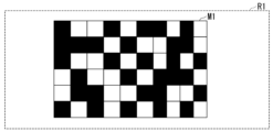
- FIG. 8 is a diagram showing an example of the binary pattern M1 of the structured detection mask 6 according to this embodiment.
- the object to be observed the cell C1 passing through the flow path 20 is irradiated with the illumination light L2 shaped by the illumination optical system 4, and the scattered light L3 emitted from the cell C1 is focused by the imaging optical system 5. It is the illuminated area in the image plane.
- the area in which the binary pattern M1 is arranged in the structured detection mask 6 is smaller than or as large as the illuminated area R1 when compared in the object plane.
- the object plane is a plane where the cell C1 exists in the channel 20 .
- Comparing the size of the binary pattern M1 of the structured detection mask 6 and the size of the cell C1 on the object plane means that the size of the image of the binary pattern M1 of the structured detection mask 6 formed on the channel 20 and the size of the flow channel 20 are compared. It means comparing the size of the cell C1 passing through the position of the image in the path 20.
- the scattered light L3 emitted when the object to be observed is irradiated with the illumination light L2 in a wide irradiation area in the length direction (streamline direction) of the flow path 20 is converted into the binary pattern M1. Efficient detection is ensured via the included transparent portion. If the area in which the binary pattern M1 is arranged is larger than the illuminated area R1, there will be areas of the binary pattern M1 that are not illuminated by the illumination light L2, resulting in portions that are not used for structured detection.
- the size of the region in which the binary pattern M1 is arranged in the structured detection mask 6 depends on the width of the channel 20, the degree of flow focusing, the size of the observation target and the target site (internal structure to be observed) of the observation target. determined based on For example, when the object to be observed is a cell C1, the width direction size of the region where the binary pattern M1 is arranged is 300 ⁇ m on the object plane in the direction perpendicular to the flow (the width direction of the channel 20). It is preferable to set as follows. On the other hand, it is preferable to set the size of the region in which the binary pattern M1 is arranged in the flow direction (the length direction of the channel 20) to be 1500 ⁇ m or less on the object surface (the position where the cell C1 exists).
- the pattern of the binary pattern M1 is determined according to the arrangement of the transmissive portions, and the transmissive portions are configured as aggregates of a plurality of pixels.
- a pixel is the smallest unit that constitutes the transparent portion of the binary pattern M1, and the transparent portion is arranged on the binary pattern M1 in units of pixels. Since the binary pattern M1 is composed of a plurality of pixels, it is possible to divide the observed object and detect scattered light for each portion.
- the binary pattern M1 is fixed and does not change while the flow cytometer 1 is measuring.
- the transmissive portions or the blocking portions are randomly arranged on the binary pattern M1 in units of pixels.
- the binary patterns M1 can be arranged linearly instead of irregularly.
- the binary pattern M1 can consist of, for example, 2 to 1 million pixels.
- the ratio of the entire transmission area in the area where the binary pattern M1 is arranged depends on the size of the observation target (the size of the target site when the target site is a part of a cell) and the irradiation of the observation target. The optimum ratio changes depending on the intensity of the illuminated illumination light L2. The intensity of the detected light increases as the percentage of the entire transmission portion increases.
- the spatial resolution can be improved by setting the ratio of the transparent portion to 10% or less of the area where the binary pattern M1 is arranged.
- the size and shape of the pixels forming the binary pattern M1 are appropriately adjusted depending on the size of the target site included in the observation object.
- the pixel size is preferably set to be sufficiently small relative to the size of the target site.
- the number of pixels depends on the cell as the object of observation.
- the size and shape are, for example, a circle with a radius of 10 ⁇ m or less or a square with a side of 10 ⁇ m or less on the object plane.
- the size and shape of the pixel are, for example, a circle with a radius of 1 ⁇ m or less or a square with a side of 1 ⁇ m or less on the object plane.
- the diameter of the nucleus of mammalian cells is approximately 6 ⁇ m.
- the pixel shape is preferably designed as a square, rectangle, circle, or ellipse, but is not limited thereto, and may be configured in other shapes such as polygons.
- FIG. 9 is a diagram showing an example of a configuration D1 for performing structured detection according to this embodiment.
- Configuration D1 is for detecting FSC in an infinite correction system by structured detection.
- the imaging optical system 5 comprises a detection lens 51, an imaging lens 52 and a light blocker 53.
- the illumination light L2 emitted from the illumination optical system 4 is applied to the cell C1 passing through the illumination position of the channel 20. Scattered light is emitted from the cell C1 irradiated with the illumination light L2. Of the scattered light, the FSC scattered in the irradiation direction of the illumination light L2 enters the detection lens 51 as the scattered light L3. Further, the component of the illumination light L2 applied to the cell C1 that has passed through the cell C1 enters the detection lens 51 as direct light L4.
- the scattered light L3 that has passed through the detection lens 51 is incident on the imaging lens 52 as a parallel light flux at infinity.
- the scattered light L3 incident on the imaging lens 52 is imaged as scattered light L5 at the position where the structured detection mask 6 is arranged.
- Scattered light L 6 which is the FSC transmitted through structured detection mask 6 , is detected by photodetector 7 .
- the configuration D1 includes the above-described first spatial separation configuration A1 (FIG. 3) as a configuration for spatially separating the propagation path of the direct light L4 and the propagation path of the scattered light L3.
- the direct light L4 is collected by the detection lens 51 and blocked by the light blocker 53 at the most focused position.
- FIG. 10 is a diagram showing an example of a configuration D1a for performing structured detection according to a modification of this embodiment.
- the configuration other than the configuration for performing structured detection is common to the first embodiment, and configuration D1a will be described here.
- Configuration D1a is a configuration for detecting FSC in a finite correction system.
- the imaging optics 5 comprises a detection lens 51 and a light blocker 53.
- the scattered light L3 that has passed through the detection lens 51 is imaged by the detection lens 51 at a position where the structured detection mask 6 is arranged.
- the direct light L4 is collected by the detection lens 51 and blocked by the light blocker 53 at the most focused position.
- FIG. 11 is a diagram showing an example of a configuration D2 for performing structured detection according to this embodiment.
- Configuration D2 is a configuration for detecting FSC by structured detection in an infinitely corrected system and for detecting FSC detected by a conventional flow cytometer.
- the same reference numerals are given to the same configurations as those of the above-described first embodiment, and the descriptions of the same configurations and operations may be omitted.
- the imaging optics 5 comprises a detection lens 51, an imaging lens 52, a light blocker 53, a beam splitter 54, a slit 55, an imaging lens 56, and a rectangular window mask 57.
- Configuration D2 includes a photodetector 70 to detect FSC as detected by a conventional flow cytometer.
- the beam splitter 54 transmits part of the incident light and reflects the remaining part.
- the slit 55 functions as a diaphragm that adjusts the amount of incident light.
- An aperture may be provided instead of the slit 55 .
- the rectangular window mask 57 is a mask having a rectangular window through which light can pass.
- the scattered light L3 that has passed through the detection lens 51 propagates toward the imaging lens 52 as a parallel light flux at infinity.
- part of the scattered light L3 is transmitted toward the imaging lens 52 and the rest is reflected toward the imaging lens 56 by the beam splitter 54 .
- the scattered light L3 transmitted towards the imaging lens 52 is collected by the imaging lens 52 and imaged as scattered light L5 at the position where the structured detection mask 6 is arranged.
- Scattered light L 6 transmitted through structured detection mask 6 is detected by photodetector 7 .
- the scattered light L6 detected by the photodetector 7 through the structured detection mask 6 contains information derived from the shape of the observed object detected by the structure of structured detection.
- the scattered light L3 reflected toward the imaging lens 56 passes through the slit 55 and is condensed by the imaging lens 56 as scattered light L50.
- the collected scattered light L50 passes through the rectangular window mask 57 and is detected by the photodetector 70 as scattered light L60.
- Scattered light L60 detected by photodetector 70 is light detected as FSC in a conventional flow cytometer.
- FIG. 12 is a diagram showing an example of a configuration D2a for performing structured detection according to a modification of this embodiment.
- Configuration D2a is a configuration for performing bright-field light detection at the same time as FSC is detected by structured detection in an infinity correction system.
- the configuration for performing structured detection is substantially the same as that of the second embodiment, so the configuration for performing bright-field light detection will be described below.
- the imaging optical system 5 includes a detection lens 51, an imaging lens 52, a mirror 53a, and an imaging lens .
- Configuration D2a comprises a structured detection mask 61 and a photodetector 71 for brightfield light detection.
- Mirror 53a reflects direct light L4 toward photodetector 71 for brightfield light detection.
- the direct light L4 since the direct light L4 is reflected by the mirror 53a, the direct light L4 does not propagate toward the photodetector 7 as in the first spatial separation arrangement A1. That is, the mirror 53a has both a function of reflecting the direct light L4 for bright field light detection and a function of blocking the direct light L4 as in the first spatial separation configuration A1.
- the structured detection mask 61 is, like the structured detection mask 6, a mask with a binary pattern.
- the direct light L4 transmitted through the detection lens 51 is reflected toward the photodetector 71 by the mirror 53a.
- the reflected direct light L4 enters the imaging lens 56 as direct light L40.
- the direct light L40 is collected by the imaging lens 56 and imaged at the location where the structured detection mask 61 is located.
- Direct light L 41 transmitted through structured detection mask 61 is detected by photodetector 71 . Since the direct light L41 (bright field light) detected by the photodetector 71 is detected through the structured detection mask 61 by the structure of structured detection, image information obtained by bright field observation of the shape of the observation target is obtained. is included.
- FIG. 13 is a diagram showing an example of the configuration D3 for performing structured detection according to this embodiment.
- Configuration D3 is a configuration for detecting BSC by structured detection in an infinitely corrected system.
- symbol may be attached
- the illumination optical system 4 includes an irradiation lens 58, a mirror 53b, and an irradiation detection lens 59.
- the imaging optical system 5 includes an irradiation detection lens 59 , a mirror 53 b and an imaging lens 52 .
- the configuration of the illumination optical system 4 and the configuration of the imaging optical system 5 share some configurations (mirror 53b and irradiation detection lens 59).
- the irradiation lens 58 converges the illumination light L21 to the position where the mirror 53b is provided.
- the mirror 53b reflects the illumination light L21 condensed by the illumination lens 58 toward the flow path 20 as the illumination light L22.
- the reflected illumination light L ⁇ b>22 is condensed by the irradiation detection lens 59 and irradiated to the irradiation position of the flow path 20 .
- the shape of the illumination light L22 is a shape that is wide in the length direction of the flow path 20, like the illumination light L2 of each of the above-described embodiments.
- the illumination light L22 emitted from the illumination optical system 4 is applied to the cell C1 passing through the irradiation position of the channel 20. Scattered light is emitted from the cell C1 irradiated with the illumination light L2. Of the scattered light, the BSC scattered in the direction opposite to the irradiation direction of the illumination light L22 enters the irradiation detection lens 59 as the scattered light L31. Further, the component of the illumination light L22 applied to the cell C1 that has passed through the cell C1 propagates as the direct light L42.
- the scattered light L31 that has passed through the irradiation detection lens 59 enters the imaging lens 52 as a parallel light flux at infinity.
- the scattered light L31 incident on the imaging lens 52 is imaged as scattered light L5 at the position where the structured detection mask 6 is arranged.
- Scattered light L 6 which is BSC transmitted through structured detection mask 6 , is detected by photodetector 7 .
- FIG. 14 is a diagram showing an example of a configuration D4 for performing structured detection according to this embodiment.
- Configuration D4 is for detecting FSC by structured detection using a reflective objective lens in an infinity corrected system.
- symbol may be attached
- the imaging optical system 5 includes a convex mirror 510 , a reflective objective lens 512 and an imaging lens 52 .
- Convex mirror 510 is a convex shaped mirror.
- Convex mirror 510 has a back surface 511 that blocks light.
- the convex mirror 510 is arranged such that the back surface 511 faces the channel 20 side.
- the reflective objective lens 512 collects incident light with a concave mirror.
- the reflective objective lens 512 is arranged such that the mirror faces the channel 20 side.
- a reflective objective lens 512 has an aperture in the center of the mirror.
- the scattered light L3 which is the FSC emitted from the cell C1 when the cell C1 is irradiated with the illumination light L2, enters the reflective objective lens 512. Further, the component of the illumination light L2 applied to the cell C1 that has passed through the cell C1 enters the convex mirror 510 as the direct light L4 and is blocked by the back surface 511 .
- the configuration D4 has, in principle, the same configuration as the first spatial separation configuration A1 (FIG. 3) as a configuration for spatially separating the propagation path of the direct light L4 and the propagation path of the scattered light L3.
- the back surface 511 of the convex mirror 510 functions as a light interrupter.
- the rear surface 591 does not have to be placed at a position corresponding to the pupil plane.
- the illumination optical system 4 needs to irradiate the illumination light L2 with a diameter smaller than the size of the back surface 511 .
- the reflective objective lens 512 reflects the incident scattered light L3 toward the flow path 20 by means of a concave mirror, and converges the light to the position where the convex mirror 510 is arranged.
- the convex mirror 510 reflects the scattered light L3 reflected by the reflective objective lens 512 toward the reflective objective lens 512 .
- the scattered light L3 passes through the opening of the mirror of the reflective objective lens 512 and propagates toward the photodetector 7 as parallel light.
- the scattered light L3 is collected by the imaging lens 52 and imaged as scattered light L51 at the position where the structured detection mask 6 is arranged.
- Scattered light L 6 which is the FSC transmitted through structured detection mask 6 , is detected by photodetector 7 .
- configuration D4 an example in which the direct light L4 is blocked by the back surface 511 of the convex mirror 510 has been described, but the configuration is not limited to this.
- a plane mirror may be arranged on the back surface 511 to reflect the direct light L4, thereby detecting the direct light L4 at the same time as the scattered light L3 (bright-field observation configuration).
- a finite correction system or an infinite correction system may be used.
- the embodiment having the configuration of the finite correction system may be changed to the configuration of the infinite correction system by changing the configuration of the optical system.
- the embodiment having the configuration of the infinite correction system may be changed to the configuration of the finite correction system by changing the configuration of the optical system.
- each of the above-described embodiments except for the third embodiment, an example of detecting FSC as scattered light L3 by structured detection has been described, but the present invention is not limited to this.
- one or more of FSC, BSC, and SSC may be detected by structured detection.
- an example of detecting only scattered light by structured detection has been described, but the present invention is not limited to this.
- the configuration of each embodiment may be modified to detect scattered light by structured detection while simultaneously detecting FSC, as detected by a conventional flow cytometer, or direct light (bright field light detection).
- each embodiment scattered light can be detected by structured detection, and fluorescence emitted by BSCs, SSCs, or measurement objects detected by conventional flow cytometers can be detected at the same time.
- the configuration of each embodiment can be configured to detect BSC, SSC, fluorescence, or bright-field light by structured detection as in FSC, which simultaneously detects the above-described BSC, SSC, and bright field light.
- the present invention is not limited to this.
- the first spatial separation configuration A2, the first spatial separation configuration A3, the first spatial separation configuration A4, and the second Any of the two spatial separation configurations B1 may be used.
- the method of blocking the direct light L4 is not limited to blocking the direct light L4 illustrated in the first spatial separation configuration A1. .
- methods such as light absorption, reflection, refraction, and diffraction may be used.
- the flow cytometer 1 includes the microfluidic device 2, the light source 3, the illumination optical system 4, the structured detection mask 6, the imaging optical system 5, and the light source. a detector 7;
- the microfluidic device 2 comprises a channel 20 through which an object to be observed (cell C1 in this embodiment) can flow together with the fluid.
- the light source 3 irradiates illumination light L ⁇ b>1 toward an observation target (cell C ⁇ b>1 in this embodiment) flowing through the channel 20 .
- the illumination optical system 4 converts the illumination light L1 emitted by the light source 3 to the illumination light L2 whose length in the length direction of the flow channel 20 is equal to or greater than the length in the width direction of the flow channel 20 at the irradiation position of the flow channel 20. shape and irradiate.
- the structured detection mask 6 has a binary pattern of transmissive areas that transmit light and blocking areas that block light.
- the imaging optical system 5 forms an image on the structured detection mask 6 of the scattered light L3 emitted from the object to be observed (in this embodiment, the cell C1) by irradiation with the illumination light L2 shaped by the illumination optical system 4. .
- the photodetector 7 detects the scattered light L6 transmitted through the transmissive portion of the structured detection mask 6.
- the scattered light from the observation target (in this embodiment, the cell C1) moving in the channel 20 passes through the transmission portion of the structured detection mask 6. detected by the photodetector 7 via the Further, in the flow cytometer 1 according to this embodiment, the propagation path of the illumination light L2 formed by the illumination optical system 4 and the scattered light L3 emitted from the observation target (cell C1 in this embodiment) are photodetected. The propagation path to detection by the detector 7 is spatially separated by the illumination optical system 4 and the imaging optical system 5 .
- the flow cytometer 1 forms the illumination light L2 whose length in the length direction of the flow channel 20 is equal to or greater than the length in the width direction of the flow channel 20, irradiates the observation object, and observes it. Scattered light emitted from the object is detected by a photodetector 7 through a structured detection mask 6 . Therefore, it is possible to acquire information derived from the shape of the observed object with higher resolution than the information derived from the shape of the observed object acquired by the conventional flow cytometer only from the scattered light by the structured detection configuration.
- the structured detection configuration is such that the structured detection mask 6 is positioned between the flow path 20 and the photodetector 7 on the optical path from the light source 3 to the photodetector 7 . It refers to the configuration that is provided.
- the scattered light emitted from the observation object in this embodiment, the cell C1 moving in the channel 20 is detected by the structured detection mask 6 due to the structured detection configuration. is detected through the transparent portion of the observation object (in this embodiment, the cell C1) moving in the channel 20 is detected by the structured detection mask 6 due to the structured detection configuration. is detected through the transparent portion of the
- the illumination optical system 4 illuminates the illumination light L1 emitted by the light source 3 so that the ratio of the length in the length direction of the flow path 20 to the length in the width direction of the flow path 20 is 10 at the irradiation position of the flow path 20.
- SYMBOLS 1 Flow cytometer, 2... Microfluidic device, 20... Channel, 3... Light source, 4... Illumination optical system, 6... Structured detection mask, 5... Imaging optical system, 7... Photodetector, C1... Cell, L1, L2... Illumination light, L3, L6... Scattered light
Abstract
This flow cytometer comprises: a microfluidic device; a light source that emits illumination light toward an observation target object flowing through a flow path; an illumination optical system that shapes the illumination light emitted by the light source into illumination light having a longitudinal-direction length of the flow path that is equal to or greater than a width-direction length of the flow path at the irradiation position in the flow path, and emits the shaped illumination light; a structured detection mask having binary patterns of transmission portions and blocking portions; an image-forming optical system that causes scattered light emitted from the observation target object by irradiation with the illumination light shaped by the illumination optical system to form an image on the structured detection mask; and an optical detector that detects scattered light which has been transmitted through the transmissive portions of the structured detection mask. The propagation path of direct light transmitted through the observation target object, among the illumination light shaped by the illumination optical system, and the propagation path until the scattered light emitted from the observation target object is detected by the optical detector are spatially divided by the illumination optical system and the image-forming optical system.
Description
本発明は、フローサイトメータに関する。
本願は、2021年9月30日に、日本に出願された特願2021-161449号に基づき優先権を主張し、その内容をここに援用する。 The present invention relates to flow cytometers.
This application claims priority based on Japanese Patent Application No. 2021-161449 filed in Japan on September 30, 2021, the contents of which are incorporated herein.
本願は、2021年9月30日に、日本に出願された特願2021-161449号に基づき優先権を主張し、その内容をここに援用する。 The present invention relates to flow cytometers.
This application claims priority based on Japanese Patent Application No. 2021-161449 filed in Japan on September 30, 2021, the contents of which are incorporated herein.
大量の細胞を高速で判別、または判別及び分取する手段は、iPS細胞(induced Pluripotent Stem Cells)などの幹細胞を用いた再生医療、CAR-T(Chimeric Antigen Receptor T cell)細胞療法などの新しいがん免疫療法の分野、創薬の分野で、強い需要がある。そのような手段として、フローサイトメトリーが知られている。フローサイトメトリーは、細胞を一定の流速で流路に沿って流しながら、特定の光を照射した際の散乱光や蛍光を取得して光学的に細胞の分析を行う技術である。
New methods for identifying, or identifying and sorting, a large number of cells at high speed include regenerative medicine using stem cells such as iPS cells (induced pluripotent stem cells), and CAR-T (chimeric antibody receptor T cell) cell therapy. There is strong demand in the fields of cancer immunotherapy and drug discovery. Flow cytometry is known as such means. Flow cytometry is a technique for optically analyzing cells by acquiring scattered light and fluorescence when cells are irradiated with specific light while flowing cells along a channel at a constant flow rate.
しかし、一般的なフローサイトメトリーにおいては、目的となる細胞の特定が蛍光の検出をベースに行なわれることが多く、蛍光マーカーを用いたラベル付けが必要となる。そのため、一般的なフローサイトメトリーを、再生医療やCAR-T細胞療法のような、分析した細胞を患者に移植あるいは投与する目的には使いにくい。蛍光マーカーを用いたラベル付けをせず(以下、ラベルフリーとも表記する)に細胞の情報を光学的に分析する方法として、例えば、散乱光を用いる方法がある(特許文献1、2)。散乱光には、散乱の方向に応じて、前方散乱光(Forward Scatter:FSC)、側方散乱光(Side Scatter:SSC)、後方散乱光(Backward Scatter:BSC)がある。
However, in general flow cytometry, target cells are often identified based on fluorescence detection, and labeling with fluorescent markers is required. Therefore, general flow cytometry is difficult to use for transplantation or administration of analyzed cells to patients, such as regenerative medicine and CAR-T cell therapy. As a method for optically analyzing cell information without labeling with a fluorescent marker (hereinafter also referred to as label-free), for example, there is a method using scattered light (Patent Documents 1 and 2). Scattered light includes forward scattered light (FSC), side scattered light (SSC), and backscattered light (backward scatter: BSC) depending on the scattering direction.
しかしながら、一般的なフローサイトメトリーにおいて取得する散乱光(FSC、SSC、BSC)からは、細胞の形状由来の情報の多くが抜け落ちており、ラベル付けを全く行うことなく散乱光から取得した情報だけで細胞を判別、または判別及び分取することは困難である。
ゴーストサイトメトリー(Ghost Cytometry:GC)技術は、従来のフローサイトメトリーに比べて、より豊富で詳細な細胞の形状由来の情報を取得することができる技術として知られている(特許文献3、4、非特許文献1)。ゴーストサイトメトリー技術を用いた散乱光の検出光学系では、例えば、観測対象物から発せられる散乱光は構造マスクパターンなどの空間変調器を観測対象物が流通する流路と検出器の間の光路に設置する構造化検出により検出される。構造化検出の構成では、流路を通過する観測対象物を照射する照明光学系の構成を単純化することができるため、装置設計の自由度が大きくなる。
一般的なフローサイトメトリーにおいては取得できない高解像度な細胞の形状由来の情報を、構造化検出の構成により散乱光のみから取得できることが求められている。 However, the scattered light (FSC, SSC, BSC) obtained in general flow cytometry lacks most of the information derived from the cell shape, and only the information obtained from the scattered light without any labeling is used. It is difficult to discriminate, or to discriminate and sort cells in a cell.
Ghost Cytometry (GC) technology is known as a technology that can obtain more abundant and detailed information derived from the shape of cells compared to conventional flow cytometry ( Patent Documents 3 and 4. , Non-Patent Document 1). In an optical system for detecting scattered light using ghost cytometry technology, for example, the scattered light emitted from an object to be observed passes through a spatial modulator, such as a structural mask pattern, in the optical path between the flow path through which the object to be observed flows and the detector. Detected by structured detection installed in In the configuration of structured detection, the configuration of the illumination optical system that irradiates the observation target passing through the channel can be simplified, so the degree of freedom in device design increases.
There is a need to obtain high-resolution information derived from the shape of cells, which cannot be obtained by general flow cytometry, only from scattered light by means of structured detection.
ゴーストサイトメトリー(Ghost Cytometry:GC)技術は、従来のフローサイトメトリーに比べて、より豊富で詳細な細胞の形状由来の情報を取得することができる技術として知られている(特許文献3、4、非特許文献1)。ゴーストサイトメトリー技術を用いた散乱光の検出光学系では、例えば、観測対象物から発せられる散乱光は構造マスクパターンなどの空間変調器を観測対象物が流通する流路と検出器の間の光路に設置する構造化検出により検出される。構造化検出の構成では、流路を通過する観測対象物を照射する照明光学系の構成を単純化することができるため、装置設計の自由度が大きくなる。
一般的なフローサイトメトリーにおいては取得できない高解像度な細胞の形状由来の情報を、構造化検出の構成により散乱光のみから取得できることが求められている。 However, the scattered light (FSC, SSC, BSC) obtained in general flow cytometry lacks most of the information derived from the cell shape, and only the information obtained from the scattered light without any labeling is used. It is difficult to discriminate, or to discriminate and sort cells in a cell.
Ghost Cytometry (GC) technology is known as a technology that can obtain more abundant and detailed information derived from the shape of cells compared to conventional flow cytometry (
There is a need to obtain high-resolution information derived from the shape of cells, which cannot be obtained by general flow cytometry, only from scattered light by means of structured detection.
本発明は上記の点に鑑みてなされたものであり、高解像度な観測対象物の形状由来の情報を構造化検出の構成により散乱光のみから取得できるフローサイトメータを提供する。
The present invention has been made in view of the above points, and provides a flow cytometer that can acquire high-resolution information derived from the shape of an observation target only from scattered light by means of structured detection.
本開示の一態様は、観測対象物が流体と共に流れ得る流路を備えるマイクロ流体装置と、前記流路を流れる前記観測対象物に向けて照明光を照射する光源と、前記光源が照射する前記照明光を、前記流路の照射位置において、前記流路の長さ方向の長さが前記流路の幅方向の長さ以上である照明光に成形して照射する照明光学系と、光を透過させる透過部と光を遮断する遮断部とのバイナリーパターンを有する構造化検出用マスクと、前記照明光学系によって成形された前記照明光の照射によって前記観測対象物から発せられる散乱光を前記構造化検出用マスクに結像させる結像光学系と、前記構造化検出用マスクが有する前記透過部を透過した散乱光を検出する光検出器と、を備え、前記照明光学系によって成形された前記照明光のうち前記観測対象物を透過した直接光の伝搬経路と、前記観測対象物から発せられる散乱光が前記光検出器によって検出されるまでの伝搬経路とは、前記照明光学系と前記結像光学系とによって空間的に分離されるフローサイトメータである。
One aspect of the present disclosure is a microfluidic device including a channel in which an observation target can flow together with a fluid, a light source that irradiates illumination light toward the observation target that flows through the channel, and the an illumination optical system that shapes and irradiates illumination light into illumination light whose length in the length direction of the flow channel is equal to or greater than the length in the width direction of the flow channel at the irradiation position of the flow channel; a structured detection mask having a binary pattern of transmitting portions for transmitting light and blocking portions for blocking light; an imaging optical system for forming an image on the structured detection mask; and a photodetector for detecting scattered light transmitted through the transmission portion of the structured detection mask, wherein the illumination optical system shapes the The propagation path of the direct light that has passed through the observation target object out of the illumination light and the propagation path until the scattered light emitted from the observation target object is detected by the photodetector are defined by the illumination optical system and the coupling. Flow cytometer spatially separated by imaging optics.
本開示の一態様は、観測対象物が流体と共に流れ得る流路を備えるマイクロ流体装置と、前記流路を流れる前記観測対象物に向けて照明光を照射する光源と、前記光源が照射する前記照明光を、前記流路の照射位置において、前記流路の長さ方向の長さの前記流路の幅方向の長さに対する比が10分の1よりも大きい照明光に成形して照射する照明光学系と、光を透過させる透過部と光が遮断される遮断部とのバイナリーパターンを有する構造化検出用マスクと、前記照明光学系によって成形された前記照明光の照射によって前記観測対象物から発せられる散乱光を前記構造化検出用マスクに結像させる結像光学系と、前記構造化検出用マスクが有する前記透過部を透過した散乱光を検出する光検出器と、を備え、前記照明光学系によって成形された前記照明光のうち前記観測対象物を透過した直接光の伝搬経路と、前記観測対象物から発せられる散乱光が前記光検出器によって検出されるまでの伝搬経路とは、前記照明光学系と前記結像光学系とによって空間的に分離されるフローサイトメータである。
One aspect of the present disclosure is a microfluidic device including a channel in which an observation target can flow together with a fluid, a light source that irradiates illumination light toward the observation target that flows through the channel, and the Illumination light is shaped into illumination light in which the ratio of the length in the length direction of the flow channel to the length in the width direction of the flow channel is greater than 1/10 at the irradiation position of the flow channel and irradiated. an illumination optical system; a structured detection mask having a binary pattern of a transmission portion that transmits light and a blocking portion that blocks light; an imaging optical system that forms an image of the scattered light emitted from the structured detection mask on the structured detection mask; and a photodetector that detects the scattered light transmitted through the transmission portion of the structured detection mask, The propagation path of the direct light transmitted through the observation object among the illumination light shaped by the illumination optical system and the propagation path until the scattered light emitted from the observation object is detected by the photodetector , a flow cytometer spatially separated by said illumination optics and said imaging optics;
また、本開示の一態様は、上記のフローサイトメータにおいて、前記照明光学系が成形する前記照明光の前記流路の長さ方向の長さの下限値は30マイクロメートル以上であって、前記流路の長さ方向の長さの上限値は2000マイクロメートル以下である。
Further, in one aspect of the present disclosure, in the flow cytometer described above, the lower limit of the length in the length direction of the flow path of the illumination light formed by the illumination optical system is 30 micrometers or more, The upper limit of the length in the longitudinal direction of the channel is 2000 micrometers or less.
また、本開示の一態様は、上記のフローサイトメータにおいて、前記照明光学系が成形する前記照明光の前記流路の長さ方向の長さの下限値は50マイクロメートル以上である。
Further, in one aspect of the present disclosure, in the flow cytometer described above, the lower limit of the length in the length direction of the flow path of the illumination light formed by the illumination optical system is 50 micrometers or more.
また、本開示の一態様は、上記のフローサイトメータにおいて、前記照明光学系が成形する前記照明光の前記流路の長さ方向の長さの上限値は、1000マイクロメートル以下である。
Further, in one aspect of the present disclosure, in the flow cytometer described above, the upper limit of the length in the length direction of the flow path of the illumination light formed by the illumination optical system is 1000 micrometers or less.
また、本開示の一態様は、上記のフローサイトメータにおいて、前記照明光学系が成形する前記照明光の前記流路の幅方向の長さの上限値は、前記流路の幅以下である。
Further, in one aspect of the present disclosure, in the flow cytometer described above, the upper limit of the length of the illumination light formed by the illumination optical system in the width direction of the flow path is equal to or less than the width of the flow path.
また、本開示の一態様は、上記のフローサイトメータにおいて、前記照明光学系が成形する前記照明光の前記流路の幅方向の長さの下限値は、前記流路を流れる前記観測対象物の流線の前記流路の幅方向の位置ずれの程度以上である。
Further, in one aspect of the present disclosure, in the flow cytometer described above, the lower limit of the length of the illumination light formed by the illumination optical system in the width direction of the flow path is the observation object flowing through the flow path. is greater than or equal to the displacement of the streamlines in the width direction of the flow path.
また、本開示の一態様は、上記のフローサイトメータにおいて、前記構造化検出用マスクは、前記バイナリーパターンが配置される領域の大きさが、物体面において幅方向に300μm以下、流れ方向に1500μm以下となるように設定され、前記バイナリーパターンが、物体面において半径10μm以下の円形または一辺10μm以下の方形からなる複数のピクセルにより形成されている。
Further, in one aspect of the present disclosure, in the flow cytometer described above, the size of the region in which the binary pattern is arranged in the structured detection mask is 300 μm or less in the width direction and 1500 μm in the flow direction on the object surface. The binary pattern is formed by a plurality of pixels each having a circle with a radius of 10 μm or less or a square with a side of 10 μm or less on the object plane.
また、本開示の一態様は、上記のフローサイトメータにおいて、前記結像光学系は、前記流路と前記構造化検出用マスクとの間に配置されて光を遮断する光遮断器をさらに備え、前記照明光学系によって成形された前記照明光のうち前記観測対象物を透過した前記直接光の伝搬経路と、前記観測対象物から発せられる散乱光が前記光検出器によって検出されるまでの伝搬経路とは、前記光遮断器が前記直接光を遮断することによって、空間的に分離される。
In one aspect of the present disclosure, in the flow cytometer described above, the imaging optical system further includes a light blocker disposed between the channel and the structured detection mask to block light. , a propagation path of the direct light transmitted through the observation object among the illumination light shaped by the illumination optical system, and a propagation path until scattered light emitted from the observation object is detected by the photodetector; Paths are spatially separated by the light isolator blocking the direct light.
また、本開示の一態様は、上記のフローサイトメータにおいて、前記光遮断器は、前記照明光学系と前記結像光学系との少なくとも一方によって、前記照明光学系によって成形された前記直接光が最も絞られる1以上の位置に配置される。
Further, according to one aspect of the present disclosure, in the flow cytometer described above, the light blocker causes at least one of the illumination optical system and the imaging optical system to block the direct light shaped by the illumination optical system. It is placed at one or more positions where it is most squeezed.
また、本開示の一態様は、上記のフローサイトメータにおいて、前記照明光学系は、成形する前記照明光のうち前記観測対象物を透過した直接光の伝搬経路の方向が、前記観測対象物から発せられる散乱光が前記光検出器によって検出されるまでの伝搬経路の方向とは異なる方向となるように前記照明光を成形する。
Further, in one aspect of the present disclosure, in the above-described flow cytometer, the illumination optical system is arranged such that the direction of the propagation path of direct light transmitted through the observation object, out of the illumination light to be shaped, is from the observation object. The illumination light is shaped such that the emitted scattered light is in a direction different from the direction of the propagation path until it is detected by the photodetector.
また、本開示の一態様は、上記のフローサイトメータにおいて、前記構造化検出用マスクにおいて前記バイナリーパターンが配置される領域は、前記照明光学系によって成形された前記照明光が前記結像光学系の結像面において照射される領域より小さい。
Further, according to one aspect of the present disclosure, in the flow cytometer described above, the region in which the binary pattern is arranged in the structured detection mask is formed by the illumination light shaped by the illumination optical system. is smaller than the illuminated area in the image plane of .
本発明によれば、高解像度な観測対象物の形状由来の情報を構造化検出の構成により散乱光のみから取得できる。
According to the present invention, information derived from the shape of a high-resolution observation object can be obtained only from scattered light by means of structured detection.
(第1の実施形態)
以下、図面を参照しながら本発明の実施形態について詳しく説明する。
[フローサイトメータの構成]
図1は、本実施形態に係るフローサイトメータ1の構成の一例を示す図である。フローサイトメータ1は、マイクロ流体装置2と、光源3と、照明光学系4と、結像光学系5と、構造化検出用マスク6と、光検出器7と、DAQデバイス8と、パーソナルコンピュータ(PC:Personal Computer)9とを備える。 (First embodiment)
BEST MODE FOR CARRYING OUT THE INVENTION Hereinafter, embodiments of the present invention will be described in detail with reference to the drawings.
[Configuration of flow cytometer]
FIG. 1 is a diagram showing an example of the configuration of aflow cytometer 1 according to this embodiment. The flow cytometer 1 comprises a microfluidic device 2, a light source 3, an illumination optics 4, an imaging optics 5, a structured detection mask 6, a photodetector 7, a DAQ device 8, and a personal computer. (PC: Personal Computer) 9.
以下、図面を参照しながら本発明の実施形態について詳しく説明する。
[フローサイトメータの構成]
図1は、本実施形態に係るフローサイトメータ1の構成の一例を示す図である。フローサイトメータ1は、マイクロ流体装置2と、光源3と、照明光学系4と、結像光学系5と、構造化検出用マスク6と、光検出器7と、DAQデバイス8と、パーソナルコンピュータ(PC:Personal Computer)9とを備える。 (First embodiment)
BEST MODE FOR CARRYING OUT THE INVENTION Hereinafter, embodiments of the present invention will be described in detail with reference to the drawings.
[Configuration of flow cytometer]
FIG. 1 is a diagram showing an example of the configuration of a
フローサイトメータ1は、観測対象物から発せられる光をゴーストサイトメトリー(Ghost Cytometry:GC)技術を用いて画像に変換可能な信号として取得する。フローサイトメータ1は、GC技術に基づいて、構造化検出によって観測対象物の形状由来の情報を取得する。ここで構造化検出とは、構造化検出用マスク6が光源3から光検出器7までの光路上において流路20と光検出器7との間の位置に備えられる構成をいう。
The flow cytometer 1 acquires light emitted from an observation target as a signal that can be converted into an image using ghost cytometry (GC) technology. The flow cytometer 1 acquires information derived from the shape of the object to be observed by structured detection based on GC technology. Here, structured detection means a configuration in which the structured detection mask 6 is provided at a position between the flow path 20 and the photodetector 7 on the optical path from the light source 3 to the photodetector 7 .
マイクロ流体装置2は、細胞C1が流体と共に流れ得る流路20を備える。流路20を流れる流体の流速は、観測対象物の測定の間は一定の速度である。また、マイクロ流体装置2は、流路20に複数の細胞を逐次流すが、観測対象物の計測中に照射位置を通過する細胞の個数は1個である。細胞C1は、観測対象物の一例である。なお、観測対象物は、細胞C1に限られず、他の例としてバクテリアなどの生体由来の微粒子、プラスティック、ビーズなどの非生体由来の微粒子などであってもよい。
The microfluidic device 2 comprises a channel 20 through which the cells C1 can flow together with the fluid. The flow velocity of the fluid flowing through the channel 20 is constant during the measurement of the observation object. In addition, although the microfluidic device 2 sequentially flows a plurality of cells into the channel 20, only one cell passes through the irradiation position during measurement of the object to be observed. A cell C1 is an example of an observation object. Note that the object to be observed is not limited to the cell C1, and may be, for example, biologically derived microparticles such as bacteria, or non-biologically derived microparticles such as plastics and beads.
ここで図には適宜、3次元直交座標系として、xyz座標系を示す。本実施形態において、x軸方向は、流路20の幅方向である。また、y軸方向は、流路20の長さ方向である。z軸方向は、流路20と直交する方向であって、流路20の深さ方向である。流路20の深さ方向は、流路20の高さ方向ともいう。流路20内の液体の流れは、y軸方向の+y方向に細胞C1を移動させる。流路20の幅方向または流路20の深さ方向とは、換言すれば、細胞C1と共に流れる流体の流線と垂直な方向である。
Here, the figure shows an xyz coordinate system as a three-dimensional orthogonal coordinate system as appropriate. In this embodiment, the x-axis direction is the width direction of the channel 20 . Also, the y-axis direction is the length direction of the channel 20 . The z-axis direction is a direction orthogonal to the channel 20 and is the depth direction of the channel 20 . The depth direction of the channel 20 is also referred to as the height direction of the channel 20 . The liquid flow in channel 20 moves cell C1 in the +y direction of the y-axis. The width direction of the channel 20 or the depth direction of the channel 20 is, in other words, the direction perpendicular to the streamline of the fluid flowing together with the cell C1.
流路20の幅、及び深さは、観測対象物により適宜選択することができる。例えば、観測対象物が細胞の場合、流路20の幅と、深さとはそれぞれ、20μmから500μm程度に設定することができるが、必ずしもこの範囲に限らない。本実施形態では、一例として、流路20の幅と、深さとは等しい。つまり、流路20の断面は正方形である。流路20の幅と、深さとは異なっていてもよい。つまり、流路20の断面は長方形であってもよい。
なお、流路20には、観測対象物が通過する流線幅を制限するためのフローフォーカシング機構をさらに追加することもできる。 The width and depth of thechannel 20 can be appropriately selected depending on the object to be observed. For example, when the object to be observed is a cell, the width and depth of the channel 20 can each be set to approximately 20 μm to 500 μm, but are not necessarily limited to this range. In this embodiment, as an example, the width and depth of the channel 20 are equal. That is, the cross section of the flow path 20 is square. The width and depth of the channel 20 may be different. In other words, the cross section of the channel 20 may be rectangular.
It should be noted that a flow focusing mechanism for limiting the width of the stream line through which the object to be observed passes can be added to thechannel 20 .
なお、流路20には、観測対象物が通過する流線幅を制限するためのフローフォーカシング機構をさらに追加することもできる。 The width and depth of the
It should be noted that a flow focusing mechanism for limiting the width of the stream line through which the object to be observed passes can be added to the
光源3は、流路20を流れる細胞C1に向けて照明光L1を照射する。光源3からの照明光L1は照明光学系4を介して流路20を流れる細胞C1を照明する。光源3が発する照明光L1は、コヒーレント光であっても、インコヒーレント光であってもよい。コヒーレント光の一例としてはレーザー光が、インコヒーレント光の一例としてはLED(light-emitting diode)光がある。本実施形態では、光源3が発する照明光L1は、一例として、コヒーレント光である。
The light source 3 irradiates the cells C1 flowing through the channel 20 with the illumination light L1. The illumination light L1 from the light source 3 illuminates the cells C1 flowing through the channel 20 via the illumination optical system 4 . The illumination light L1 emitted by the light source 3 may be coherent light or incoherent light. An example of coherent light is laser light, and an example of incoherent light is light-emitting diode (LED) light. In this embodiment, the illumination light L1 emitted by the light source 3 is, for example, coherent light.
照明光学系4は、流路20を通過する細胞C1を空間的に略一様に照明するための機構である。照明光学系4は、ミラー、レンズのうち少なくとも一方の光学素子を含む。照明光学系4は、光を成形するスリットや、その他の光学素子をさらに含んでもよい。なお、照明光学系を構成する光学素子は光源3が照射する照明光L1の光質、光源3から流路20の照射位置までの光路、照明光と散乱光の分離方法に応じて異なる。
The illumination optical system 4 is a mechanism for spatially and substantially uniformly illuminating the cells C1 passing through the channel 20 . The illumination optical system 4 includes at least one optical element of a mirror and a lens. The illumination optical system 4 may further include a slit for shaping light and other optical elements. The optical elements constituting the illumination optical system differ depending on the light quality of the illumination light L1 emitted by the light source 3, the optical path from the light source 3 to the irradiation position of the flow path 20, and the separation method of the illumination light and the scattered light.
照明光学系4は、光源3が照射する照明光L1を、流路20の照射位置において、所定の形状の照明光L2に成形して照射する。図1においては当該所定の形状の照明光L2が、一例として、直方体を用いて示されている。照明光L2は、平行光とされることが好ましい。
The illumination optical system 4 shapes the illumination light L1 emitted by the light source 3 into the illumination light L2 having a predetermined shape at the irradiation position of the flow path 20 and irradiates the illumination light L2. In FIG. 1, the illumination light L2 having the predetermined shape is shown using a rectangular parallelepiped as an example. The illumination light L2 is preferably parallel light.
ここで図2を参照し、照明光L2の形状について説明する。図2は、本実施形態に係る照明光L2の形状の一例を示す図である。図2は、流路20の照射位置に照射される照明光L2の形状を図1に示す流路20を上側からみた場合について示している。流路20の照射位置における照明光L2の形状は、略長方形である。当該長方形は、流路20の幅方向の長さが幅方向長さW1であり、流路20の長さ方向の長さが長さ方向長さW2である。流路20の長さ方向は流路20を流れる流体の流れ方向である。本実施形態では、長さ方向長さW2は、幅方向長さW1よりも長い。換言すれば、幅方向長さW1、及び長さ方向長さW2は、それぞれ、長方形の短辺、及び長辺に、それぞれ相当する。したがって、照明光学系4は、光源3が照射する照明光L1を、流路20の照射位置において、長さ方向長さW2が幅方向長さW1以上である照明光L2に成形して照射する。
The shape of the illumination light L2 will now be described with reference to FIG. FIG. 2 is a diagram showing an example of the shape of illumination light L2 according to this embodiment. FIG. 2 shows the shape of the illumination light L2 irradiated to the irradiation position of the flow path 20 when the flow path 20 shown in FIG. 1 is viewed from above. The shape of the illumination light L2 at the irradiation position of the channel 20 is substantially rectangular. The rectangle has a width direction length W1 in the width direction of the flow channel 20 and a length direction length W2 in the length direction of the flow channel 20 . The length direction of the channel 20 is the flow direction of the fluid flowing through the channel 20 . In this embodiment, the length W2 is longer than the width W1. In other words, the widthwise length W1 and the lengthwise length W2 correspond to the short side and long side of the rectangle, respectively. Therefore, the illumination optical system 4 shapes the illumination light L1 emitted by the light source 3 into illumination light L2 having a length W2 equal to or greater than the width W1 at the irradiation position of the flow path 20. .
長さ方向長さW2は、30μmから2000μmの範囲のいずれかの長さである。より好ましくは、長さ方向長さW2は、50μmから1000μmの範囲のいずれかの長さである。
The longitudinal length W2 is any length in the range from 30 μm to 2000 μm. More preferably, the longitudinal length W2 is any length in the range of 50 μm to 1000 μm.
長さ方向長さW2の範囲として、上記の50μmから1000μmの範囲は、実用的な観点から下限値と上限値とから定められている。
GC技術を用い観測対象物の形状由来の情報を詳細に取得するため、観測対象物に照射する照明光L2の長さ方向長さW2は、観測対象物の大きさ(例えば、細胞サイズCZ1)よりも十分に長いことが好ましい。上述したように細胞サイズCZ1は、5μmから20μm程度の大きさである。この点において、少なくとも長さ方向長さW2は、観測対象物である細胞C1の細胞サイズCZ1より大きいことが必要であり、細胞C1から発せられる散乱光を蛍光標識せずに細胞C1を判別できる程度に解像度の高い形状由来の情報として取得するためには、照明光L2の長さ方向長さW2は50μm以上の長さに設定することが望ましく、100μm以上の長さに設定することがより望ましい。 As the range of the longitudinal length W2, the above range of 50 μm to 1000 μm is determined from a practical point of view with a lower limit and an upper limit.
In order to obtain detailed information derived from the shape of the observation object using GC technology, the length W2 of the illumination light L2 irradiated to the observation object is the size of the observation object (for example, the cell size CZ1) is preferably sufficiently longer than As described above, the cell size CZ1 is about 5 μm to 20 μm. In this respect, at least the length W2 in the longitudinal direction needs to be larger than the cell size CZ1 of the cell C1, which is the object of observation, so that the cell C1 can be identified without fluorescently labeling the scattered light emitted from the cell C1. In order to obtain shape-derived information with a sufficiently high resolution, the length W2 in the length direction of the illumination light L2 is preferably set to a length of 50 μm or more, and more preferably set to a length of 100 μm or more. desirable.
一方、光源3から照射される照明光L1の光量が一定であるとすると、照明光L2を広く照射すると、照明光L2の単位面積当たりの光量は減少する。照明光L2の単位面積当たりの光量は小さすぎると、ノイズに対するシグナルの比(S/N比)が小さくなってしまう。そのため、流路20の幅方向に必要な長さを確保しつつ、S/N比を十分大きく維持するために、照明光L2の長さ方向長さW2は、1000μm以下であることが好ましい。照明光L2の長さ方向長さW2は、500μm以下であることがより好ましい。
On the other hand, assuming that the amount of illumination light L1 emitted from the light source 3 is constant, the amount of illumination light L2 per unit area decreases when the illumination light L2 is applied widely. If the amount of light per unit area of the illumination light L2 is too small, the ratio of signal to noise (S/N ratio) will become small. Therefore, in order to maintain a sufficiently high S/N ratio while ensuring the required length in the width direction of the flow path 20, the longitudinal length W2 of the illumination light L2 is preferably 1000 μm or less. More preferably, the length W2 of the illumination light L2 is 500 μm or less.
さらに、長さ方向長さW2を長くすると散乱光の検出にはより長い時間を要するため、スループット(フローサイトメータの1サンプルあたりの測定速度)は遅くなる。つまり、長さ方向長さW2を長く設定すると、所望のスループットが得られない場合がある。この点から、スループットが所望のスループット未満とならないように、長さ方向長さW2を決定する必要がある。
このように、実用的な観点から、長さ方向長さW2は、50μmから1000μmの範囲が望ましい。 Furthermore, if the longitudinal length W2 is lengthened, it takes a longer time to detect the scattered light, so the throughput (measurement speed per sample of the flow cytometer) slows down. In other words, if the longitudinal length W2 is set long, the desired throughput may not be obtained. From this point, it is necessary to determine the longitudinal length W2 so that the throughput does not fall below the desired throughput.
Thus, from a practical point of view, the longitudinal length W2 is desirably in the range of 50 μm to 1000 μm.
一方、長さ方向長さW2の範囲として、上記の30μmから2000μmの範囲は、原理的な下限値と上限値とから定められている。
上記の30μmという長さ方向長さW2の下限値は、例えば、後述するように照明光L2は構造化検出用マスク6に結像するが、上記の30μmという下限値は、細胞C1の判別に求められる解像度に応じた最低のピクセル数(例えば、70~80ピクセル)が有効に配置できる長さを考慮して定められる下限値である。 On the other hand, as the range of the longitudinal length W2, the above range of 30 μm to 2000 μm is determined based on the theoretical lower limit and upper limit.
The lower limit of the longitudinal length W2 of 30 μm, for example, causes the illumination light L2 to form an image on the structureddetection mask 6 as will be described later, but the lower limit of 30 μm is not sufficient for discrimination of the cell C1. The minimum number of pixels (for example, 70 to 80 pixels) according to the required resolution is the lower limit determined in consideration of the length that can be effectively arranged.
上記の30μmという長さ方向長さW2の下限値は、例えば、後述するように照明光L2は構造化検出用マスク6に結像するが、上記の30μmという下限値は、細胞C1の判別に求められる解像度に応じた最低のピクセル数(例えば、70~80ピクセル)が有効に配置できる長さを考慮して定められる下限値である。 On the other hand, as the range of the longitudinal length W2, the above range of 30 μm to 2000 μm is determined based on the theoretical lower limit and upper limit.
The lower limit of the longitudinal length W2 of 30 μm, for example, causes the illumination light L2 to form an image on the structured
上記の2000μmという長さ方向長さW2の上限値は、結像光学系5に備えられる光学系によって決まる限界によって定められる上限値である。光学系によって決まる限界とは、例えば、対物レンズの視野の大きさである。対物レンズの視野の大きさを超えて長さ方向長さW2を長くした場合、対物レンズの視野の外を通過している時期において細胞C1から散乱光が発せられても、そのような散乱光についてはそもそも光検出器7によって検出できない。
The upper limit of the longitudinal length W2 of 2000 μm is an upper limit determined by the optical system provided in the imaging optical system 5 . The limit determined by the optical system is, for example, the size of the field of view of the objective lens. When the longitudinal length W2 is made longer than the size of the field of view of the objective lens, even if scattered light is emitted from the cell C1 during the period when it passes outside the field of view of the objective lens, such scattered light cannot be detected by the photodetector 7 in the first place.
図2に示す一例では、幅方向長さW1は、流路20の幅の長さである流路幅X1よりも短い。幅方向長さW1は、流路幅X1以下であることが好ましい。幅方向長さW1が流路幅X1より長い場合、細胞C1が通過することのない流路20の外側にまで照明光L2が余分に照射されてしまい、光量が無駄になってしまうためである。流路幅X1は、流路20が細胞C1を含む流体を目詰まりさせず、かつ細胞C1にダメージを与えることなく流通できる大きさに設定される。一般的な細胞の細胞サイズCZ1が5μmから20μm程度の大きさであることを鑑みると、流路幅X1は、50μmから300μmの範囲で設定されることが多い。一例として流路幅X1が100μmである場合、幅方向長さW1は、100μm以下に設定される。
In the example shown in FIG. 2 , the widthwise length W1 is shorter than the channel width X1, which is the length of the width of the channel 20 . The widthwise length W1 is preferably equal to or less than the channel width X1. This is because, if the widthwise length W1 is longer than the channel width X1, the illumination light L2 is excessively irradiated to the outside of the channel 20 through which the cells C1 do not pass, and the amount of light is wasted. . The channel width X1 is set to a size that allows the fluid containing the cells C1 to flow through the channel 20 without clogging and damaging the cells C1. Considering that the cell size CZ1 of general cells is about 5 μm to 20 μm, the channel width X1 is often set in the range of 50 μm to 300 μm. As an example, when the channel width X1 is 100 μm, the widthwise length W1 is set to 100 μm or less.
幅方向長さW1は、細胞C1の流線の位置ずれの程度以上であることが好ましい。流線の位置ずれとは、流路を流体と共に流れる観測対象物の通過位置が、流路の幅方向にばらつき一定にならないことを指す。幅方向長さW1が流線の位置ずれの程度以上である場合、細胞C1の流線の位置ずれが発生した場合であっても、細胞C1が照明光L2の照射位置を外れ照射される照明光L2の強度が大きく変化してしまうことを抑制できる。
The width-direction length W1 is preferably equal to or greater than the extent of positional deviation of the streamline of the cell C1. The positional deviation of the streamline means that the passing position of the observation target flowing along with the fluid in the channel varies in the width direction of the channel and is not constant. When the width-direction length W1 is greater than or equal to the positional displacement of the streamline, the cell C1 is irradiated outside the irradiation position of the illumination light L2 even when the positional displacement of the streamline of the cell C1 occurs. A large change in the intensity of the light L2 can be suppressed.
また、幅方向長さW1は、細胞サイズCZ1以上であることが好ましい。細胞サイズCZ1は、観測対象物である細胞C1の大きさである。細胞サイズCZ1は、細胞の種類により異なるが、5μmから20μm程度の大きさであるものが多い。フローサイトメータ1では、観測対象物の形状由来の情報を取得するため、観測対象物を構成する全ての部分に照明光L2が照射されることが好ましい。そのため、幅方向長さW1は観測対象物の大きさ以上であることが好ましい。
Also, the width-direction length W1 is preferably equal to or larger than the cell size CZ1. The cell size CZ1 is the size of the cell C1, which is the object of observation. The cell size CZ1 varies depending on the type of cell, but most of them have a size of about 5 μm to 20 μm. Since the flow cytometer 1 acquires information derived from the shape of the observation object, it is preferable that the illumination light L2 is applied to all the parts constituting the observation object. Therefore, the widthwise length W1 is preferably equal to or greater than the size of the observed object.
ここで、従来のフローサイトメータにおいて、前方散乱光(Forward Scatter:FSC)を取得するための照明光は、当該FSCを取得するだけでなく蛍光色素を励起するための照明光でもあるため、高い強度で細胞に照射される必要があった。そのため、照明光は集光される必要があった。一方、流線の位置ずれが発生しても、細胞に照射される照明光の強度が大きく変化してしまうことを抑制するためには、照明光は流路の幅方向に広くされることが求められる。これらの要請によって、従来のフローサイトメータにおいては、流線の位置ずれを考慮して流路の幅方向に広く、流路の流れ方向(流線方向)には狭く照明光が照射されていた。
Here, in a conventional flow cytometer, the illumination light for acquiring forward scattered light (Forward Scatter: FSC) is not only for acquiring the FSC but also for exciting the fluorescent dye. It was necessary to irradiate the cells with intensity. Therefore, the illumination light had to be condensed. On the other hand, in order to suppress a large change in the intensity of the illumination light irradiating the cells even when the positional deviation of the streamline occurs, it is necessary to widen the illumination light in the width direction of the channel. Desired. Due to these demands, conventional flow cytometers irradiate illumination light broadly in the width direction of the channel and narrowly in the flow direction (streamline direction) of the channel in consideration of the positional deviation of the streamline. .
一方、上述したように、本実施形態に係るフローサイトメータ1では、細胞C1からの散乱光を、構造化検出によって、GC技術を用いて画像に変換可能な信号として取得する。構造化検出のため、フローサイトメータ1では、流路20を通過する細胞C1から発せられた散乱光を構造化検出用マスク6のパターンを経験させて取得する必要がある。そのため、フローサイトメータ1では、流路20の流れ方向(流線方向)には広く照明光L2を照射する必要が生じる。
On the other hand, as described above, the flow cytometer 1 according to the present embodiment acquires the scattered light from the cell C1 as a signal that can be converted into an image using GC technology by structured detection. For structured detection, the flow cytometer 1 needs to experience the pattern of the structured detection mask 6 and acquire the scattered light emitted from the cell C1 passing through the channel 20 . Therefore, in the flow cytometer 1, it is necessary to irradiate the illumination light L2 widely in the flow direction (streamline direction) of the flow channel 20. FIG.
なお、本実施形態では、長さ方向長さW2が幅方向長さW1よりも長い場合の一例について説明するが、これに限られない。従来のフローサイトメータでは、FSCを取得するために、典型的には、流路の幅方向に100μm程度、流路の長さ方向に10μm程度の広さの照明光を流路に照射していた。つまり、従来のフローサイトメータにおいて用いられる照明光では、流路の長さ方向の長さは、流路の幅方向の長さに対して10分の1程度にして照射されていた。一方、本実施形態に係るフローサイトメータ1では、照明光L2の形状について流路20の長さ方向の長さの流路20の幅方向の長さに対する比は、従来のフローサイトメータにおいて用いられた照明光に比べて大きい。それにより、従来に比べて流路の流れの方向に広がった照明光L2を照射することができる。
In this embodiment, an example in which the length W2 in the length direction is longer than the length W1 in the width direction will be described, but it is not limited to this. In conventional flow cytometers, in order to obtain FSC, the channel is typically irradiated with illumination light having a width of about 100 μm in the width direction of the channel and about 10 μm in the length direction of the channel. rice field. In other words, the illumination light used in the conventional flow cytometer irradiates with the length of the channel in the longitudinal direction being about 1/10 of the length in the width direction of the channel. On the other hand, in the flow cytometer 1 according to the present embodiment, the ratio of the length in the length direction of the flow channel 20 to the length in the width direction of the flow channel 20 for the shape of the illumination light L2 is large compared to the illumination light. As a result, it is possible to irradiate the illumination light L2 that spreads in the flow direction of the flow channel compared to the conventional art.
つまり、フローサイトメータ1では、照明光L2の形状について流路20の長さ方向の長さ(長さ方向長さW2)の流路20の幅方向の長さ(幅方向長さW1)に対する比が、10分の1よりも大きい所定の比であればよい。例えば、長さ方向長さW2の幅方向長さW1に対する比は、5分の1であってもよい。その場合であっても、長さ方向長さW2の範囲は、原理的な要請から30μmから2000μmの範囲である。
That is, in the flow cytometer 1, regarding the shape of the illumination light L2, the length in the length direction of the channel 20 (length in the length direction W2) is The ratio may be any predetermined ratio greater than one tenth. For example, the ratio of the longitudinal length W2 to the widthwise length W1 may be 1/5. Even in that case, the range of the length W2 in the longitudinal direction is within the range of 30 μm to 2000 μm from the theoretical requirement.
長さ方向長さW2を30μmから2000μmの範囲において変化させる場合には、細胞C1に照射される照明光L2の強度を所定以上とするために、長さ方向長さW2の幅方向長さW1に対する比は、10分の1よりも大きい所定の比に保ったまま長さ方向長さW2、及び幅方向長さW1が変化させられることが好ましい。なお、照明光L2の強度が所定以上であれば、長さ方向長さW2の幅方向長さW1に対する比は、10分の1よりも大きければ当該所定の比から変化してもよい。
When changing the length W2 in the range of 30 μm to 2000 μm, the width W1 Preferably, the longitudinal length W2 and the widthwise length W1 are varied while maintaining a predetermined ratio of greater than 1/10. If the intensity of the illumination light L2 is greater than or equal to a predetermined value, the ratio of the lengthwise length W2 to the widthwise length W1 may be changed from the predetermined ratio as long as it is greater than 1/10.
図1に戻ってフローサイトメータ1の構成の説明を続ける。
照明光学系4によって成形された照明光L2は流路20において照射位置に照射される。細胞C1は、当該照射位置を通過すると照明光L2によって照射される。照明光L2が細胞C1に照射されると、当該照明光L2は、細胞C1によって散乱されて、細胞C1から散乱光L3が発せられる。また、照明光L2が細胞C1に照射されると、細胞C1内包する蛍光分子が励起され発光する。当該蛍光分子が発光する場合、細胞C1からは蛍光が発せられる。細胞C1に照射された照明光L2のうち細胞C1を透過した成分は、直接光L4(透過光ともいう)として結像光学系5へと伝搬する。 Returning to FIG. 1, the description of the configuration of theflow cytometer 1 is continued.
The illumination light L<b>2 shaped by the illuminationoptical system 4 is applied to the irradiation position in the flow path 20 . The cell C1 is irradiated with the illumination light L2 after passing through the irradiation position. When the cell C1 is irradiated with the illumination light L2, the illumination light L2 is scattered by the cell C1, and the scattered light L3 is emitted from the cell C1. Further, when the cell C1 is irradiated with the illumination light L2, the fluorescent molecules contained in the cell C1 are excited and emit light. When the fluorescent molecule emits light, fluorescence is emitted from the cell C1. A component of the illumination light L2 applied to the cell C1 that has passed through the cell C1 propagates to the imaging optical system 5 as direct light L4 (also referred to as transmitted light).
照明光学系4によって成形された照明光L2は流路20において照射位置に照射される。細胞C1は、当該照射位置を通過すると照明光L2によって照射される。照明光L2が細胞C1に照射されると、当該照明光L2は、細胞C1によって散乱されて、細胞C1から散乱光L3が発せられる。また、照明光L2が細胞C1に照射されると、細胞C1内包する蛍光分子が励起され発光する。当該蛍光分子が発光する場合、細胞C1からは蛍光が発せられる。細胞C1に照射された照明光L2のうち細胞C1を透過した成分は、直接光L4(透過光ともいう)として結像光学系5へと伝搬する。 Returning to FIG. 1, the description of the configuration of the
The illumination light L<b>2 shaped by the illumination
結像光学系5は、細胞C1から発せられる散乱光L3を構造化検出用マスク6に結像させる。結像光学系5は、結像レンズを含む。当該結像レンズによって、散乱光L3は集光され構造化検出用マスク6が備えられる位置に結像される。図1では、結像レンズによって集光された散乱光L3を散乱光L5として示している。結像光学系5は、無限遠補正系、有限補正系のいずれでもよい。結像光学系5の構成の具体例は後述する。
The imaging optical system 5 forms an image of the scattered light L3 emitted from the cell C1 on the structured detection mask 6. The imaging optical system 5 includes an imaging lens. By means of said imaging lens the scattered light L3 is collected and imaged onto a position where the structured detection mask 6 is provided. In FIG. 1, the scattered light L3 condensed by the imaging lens is shown as scattered light L5. The imaging optical system 5 may be either an infinite correction system or a finite correction system. A specific example of the configuration of the imaging optical system 5 will be described later.
構造化検出用マスク6は、透過部と遮断部とを有する。透過部は、光を透過させる領域である。遮断部は、光を遮断する領域である。遮断部における光の遮断には、光の吸収、反射、屈折、回折などの方法が単独あるいは組み合わせて用いられる。構造化検出用マスク6は、透過部と遮断部からなるバイナリーパターンを有し、透過部の配置に応じて光を透過する領域のパターンが決定される。散乱光L5のうち構造化検出用マスク6が有する透過部を透過した成分のみが、光検出器7によって検出される。図1では、散乱光L5のうち透過部を透過した成分を散乱光L6として示している。
The structured detection mask 6 has a transmitting portion and a blocking portion. The transmissive portion is a region through which light is transmitted. A blocking part is a region that blocks light. For blocking light at the blocking portion, methods such as absorption, reflection, refraction, and diffraction of light are used singly or in combination. The structured detection mask 6 has a binary pattern consisting of transmissive portions and blocking portions, and the pattern of regions through which light is transmitted is determined according to the arrangement of the transmissive portions. Only that component of the scattered light L5 that has passed through the transmissive portions of the structured detection mask 6 is detected by the photodetector 7 . In FIG. 1, the component of the scattered light L5 that has passed through the transmitting portion is shown as the scattered light L6.
光検出器7は、構造化検出用マスク6が有する透過部を透過した散乱光L6を検出する。光検出器7が検出する散乱光L6は、いずれの方向に散乱する散乱光であってもよい。つまり、散乱光L6は、FSC、側方散乱光(Side Scatter:SSC)、後方散乱光(Backward Scatter:BSC)のいずれであってもよい。本実施形態では、一例として、散乱光L6としてFSCが検出される場合について説明する。即ち、本実施形態では、一例として、細胞C1により発せられる散乱光のうち、前方に散乱されたFSCが構造化検出の構成により検出されている場合について説明されている。
The photodetector 7 detects the scattered light L6 that has passed through the transmissive portion of the structured detection mask 6 . The scattered light L6 detected by the photodetector 7 may be scattered light scattered in any direction. That is, the scattered light L6 may be FSC, side scatter (SSC), or backscatter light (Backward scatter: BSC). In this embodiment, as an example, a case where FSC is detected as scattered light L6 will be described. That is, in the present embodiment, as an example, a case is described in which the forward scattered FSC among the scattered light emitted by the cell C1 is detected by the structured detection configuration.
DAQデバイス8は、光検出器7が出力する電気信号波形を、波形毎に電子データに変換する。電子データには、時間と、電気信号の強度との組み合わせが含まれる。DAQデバイス8は、一例として、オシロスコープである。
The DAQ device 8 converts the electrical signal waveform output by the photodetector 7 into electronic data for each waveform. Electronic data includes a combination of time and strength of electrical signals. DAQ device 8 is, for example, an oscilloscope.
PC8は、DAQデバイス8から出力される電子データに基づいて、細胞C1の分析を行い光学情報を生成する。またPC8は、自ら生成した光学情報を記憶することもできる。
Based on the electronic data output from the DAQ device 8, the PC 8 analyzes the cell C1 and generates optical information. The PC 8 can also store optical information generated by itself.
上述したように、細胞C1から発せられる散乱光L3が結像光学系5によって結像される位置に、バイナリーパターンを有する構造化検出用マスク6は配置される。これによって、光検出器7によって検出される散乱光L6は、細胞C1の形状由来の情報が畳み込まれている信号となる。
細胞C1が流路20中を移動してゆくと、構造化検出用マスク6上の細胞C1が結像される位置は細胞C1の移動に応じて変化する。構造化検出用マスク6が有するバイナリーパターンがランダムパターンである場合、即ち構造化検出用マスク6の光を透過する領域(透過部)が規則性なく配置される場合、細胞C1が流路20を移動する際に検出される散乱光L6の強度の時系列変化から、例えば細胞C1の形状を推定することが可能となる。 As described above, the structureddetection mask 6 having a binary pattern is placed at the position where the scattered light L3 emitted from the cell C1 is imaged by the imaging optics 5. FIG. As a result, the scattered light L6 detected by the photodetector 7 becomes a signal convoluted with information derived from the shape of the cell C1.
As the cell C1 moves through thechannel 20, the position where the cell C1 is imaged on the structured detection mask 6 changes according to the movement of the cell C1. When the binary pattern of the structured detection mask 6 is a random pattern, that is, when the light-transmitting regions (transmissive portions) of the structured detection mask 6 are arranged without regularity, the cells C1 pass through the channel 20. For example, the shape of the cell C1 can be estimated from time-series changes in the intensity of the scattered light L6 detected during movement.
細胞C1が流路20中を移動してゆくと、構造化検出用マスク6上の細胞C1が結像される位置は細胞C1の移動に応じて変化する。構造化検出用マスク6が有するバイナリーパターンがランダムパターンである場合、即ち構造化検出用マスク6の光を透過する領域(透過部)が規則性なく配置される場合、細胞C1が流路20を移動する際に検出される散乱光L6の強度の時系列変化から、例えば細胞C1の形状を推定することが可能となる。 As described above, the structured
As the cell C1 moves through the
なお、構造化検出用マスク6が有するバイナリーパターンが流路20の長さ方向(流線方向)に、画像再構成に十分な長さでなくとも、機械学習を用いることにより、一度学習した目的細胞等を判別することが可能となる(例えば、特許文献3、4、非特許文献1参照)。
Even if the binary pattern possessed by the structured detection mask 6 does not have a sufficient length for image reconstruction in the length direction (streamline direction) of the flow path 20, machine learning can be used to achieve the purpose once learned. It becomes possible to discriminate cells and the like (see, for example, Patent Documents 3 and 4 and Non-Patent Document 1).
ここでフローサイトメータ1では、直接光L4の伝搬経路と散乱光L3の伝搬経路とは、照明光学系4と結像光学系5とによって空間的に分離される。直接光L4は、上述したように照明光学系4によって成形された照明光L2のうち細胞C1を透過した成分である。したがって、照明光学系4によって成形された照明光L2の伝搬経路と、細胞C1から発せられる散乱光L3が光検出器7によって検出されるまでの伝搬経路とは、照明光学系4と結像光学系5とによって空間的に分離される。なお、散乱光L3は、構造化検出用マスク6を介し光検出器7によって散乱光L6として検出される。
Here, in the flow cytometer 1, the propagation path of the direct light L4 and the propagation path of the scattered light L3 are spatially separated by the illumination optical system 4 and the imaging optical system 5. The direct light L4 is a component of the illumination light L2 shaped by the illumination optical system 4 as described above and transmitted through the cell C1. Therefore, the propagation path of the illumination light L2 formed by the illumination optical system 4 and the propagation path until the scattered light L3 emitted from the cell C1 is detected by the photodetector 7 are the illumination optical system 4 and the imaging optical system. are spatially separated by system 5. The scattered light L3 is detected as scattered light L6 by the photodetector 7 through the structured detection mask 6. FIG.
[直接光と散乱光とを空間的に分離するための構成]
ここで図3から図7を参照し、直接光L4の伝搬経路と散乱光L3の伝搬経路とを、照明光学系4と結像光学系5とによって空間的に分離するための構成について説明する。当該構成の一例は、光遮断器によって直接光L4を遮断する構成(第1の空間分離構成という)である。また、当該構成の別の一例は、光遮断器は設けずに、結像光学系5の光軸の方向を直接光L4が伝搬する方向からずらす構成(第2の空間分離構成という)である。 [Configuration for Spatial Separation of Direct Light and Scattered Light]
Here, referring to FIGS. 3 to 7, a configuration for spatially separating the propagation path of the direct light L4 and the propagation path of the scattered light L3 by the illuminationoptical system 4 and the imaging optical system 5 will be described. . An example of the configuration is a configuration (referred to as a first spatial separation configuration) in which the direct light L4 is blocked by an optical cutoff. Another example of the configuration is a configuration in which the direction of the optical axis of the imaging optical system 5 is shifted from the direction in which the direct light L4 propagates (referred to as a second spatial separation configuration) without providing an optical blocker. .
ここで図3から図7を参照し、直接光L4の伝搬経路と散乱光L3の伝搬経路とを、照明光学系4と結像光学系5とによって空間的に分離するための構成について説明する。当該構成の一例は、光遮断器によって直接光L4を遮断する構成(第1の空間分離構成という)である。また、当該構成の別の一例は、光遮断器は設けずに、結像光学系5の光軸の方向を直接光L4が伝搬する方向からずらす構成(第2の空間分離構成という)である。 [Configuration for Spatial Separation of Direct Light and Scattered Light]
Here, referring to FIGS. 3 to 7, a configuration for spatially separating the propagation path of the direct light L4 and the propagation path of the scattered light L3 by the illumination
図3は、本実施形態に係る第1空間分離構成A1を示す図である。第1空間分離構成A1は、第1の空間分離構成の一例である。第1空間分離構成A1では、結像光学系5は、検出レンズ51と、結像レンズ52と、光遮断器53とを備える。結像光学系5の光軸を結像光学系光軸AX1とする。検出レンズ51、光遮断器53、及び結像レンズ52は、この順に流路20から光検出器7の方へ結像光学系光軸AX1上に備えられる。つまり、検出レンズ51は、結像光学系5が備える結像レンズのうち最も流路20に近い位置に備えられる。結像レンズ52は、結像光学系5が備える結像レンズのうち最も光検出器7に近い位置に備えられる。
FIG. 3 is a diagram showing the first spatial separation configuration A1 according to this embodiment. The first spatial separation configuration A1 is an example of a first spatial separation configuration. In the first spatial separation configuration A<b>1 , the imaging optical system 5 includes a detection lens 51 , an imaging lens 52 and an optical blocker 53 . The optical axis of the imaging optical system 5 is defined as an imaging optical system optical axis AX1. The detection lens 51, the light interrupter 53, and the imaging lens 52 are provided in this order from the flow path 20 toward the photodetector 7 on the imaging optical system optical axis AX1. That is, the detection lens 51 is provided at a position closest to the flow path 20 among the imaging lenses provided in the imaging optical system 5 . The imaging lens 52 is provided at a position closest to the photodetector 7 among the imaging lenses provided in the imaging optical system 5 .
照明光学系4から照射された照明光L2のうち流路20を流れる細胞C1を透過した成分は、直接光L4として結像光学系5へと入射する。図3では、照明光L2は、照明光学系4により平行光として流路20を流れる細胞C1に入射している。そのため、直接光L4の伝搬方向は、結像光学系光軸AX1と略平行である。結像光学系5へと入射した直接光L4は、結像光学系光軸AX1と略平行に光検出器7の方へと伝搬する。直接光L4は検出レンズ51によって集光される。
A component of the illumination light L2 emitted from the illumination optical system 4 that has passed through the cells C1 flowing through the channel 20 enters the imaging optical system 5 as direct light L4. In FIG. 3 , the illumination light L2 is incident on the cells C1 flowing through the channel 20 as parallel light by the illumination optical system 4 . Therefore, the propagation direction of the direct light L4 is substantially parallel to the imaging optical system optical axis AX1. The direct light L4 incident on the imaging optical system 5 propagates toward the photodetector 7 substantially parallel to the optical axis AX1 of the imaging optical system. The direct light L4 is condensed by the detection lens 51. FIG.
ここで位置P1は、結像光学系光軸AX1上において直接光L4が検出レンズ51によって最も絞られる位置である。第1空間分離構成A1では、位置P1は、結像光学系光軸AX1上において検出レンズ51と結像レンズ52との間の位置である。図3では、光遮断器53は結像光学系光軸AX1上の位置P1に設置されている。
Here, the position P1 is the position where the direct light L4 is most focused by the detection lens 51 on the imaging optical system optical axis AX1. In the first spatial separation configuration A1, the position P1 is a position between the detection lens 51 and the imaging lens 52 on the imaging optical system optical axis AX1. In FIG. 3, the light interrupter 53 is installed at a position P1 on the imaging optical system optical axis AX1.
光遮断器53は、自身に入射する光を遮断し透過させない。つまり、光遮断器53は、自身に入射する直接光L4を遮断する。光遮断器53の大きさは、直接光L4が自身に入射する場合の直接光L4の伝搬方向と直交する方向の広がりに比べて大きい。光遮断器53は、例えば、遮光板である。
The light blocker 53 blocks and does not transmit light incident on itself. That is, the light blocker 53 blocks the direct light L4 incident thereon. The size of the light blocker 53 is larger than the spread in the direction orthogonal to the propagation direction of the direct light L4 when the direct light L4 is incident on itself. The light interrupter 53 is, for example, a light blocking plate.
光遮断器53は、結像光学系光軸AX1において流路20と構造化検出用マスク6との間に配置される。第1空間分離構成A1では、光遮断器53は、位置P1に配置される。図3の例のように光遮断器53は位置P1に配置されることが好ましいが、流路20と構造化検出用マスク6との間であれば結像光学系光軸AX1上のいずれの位置に配置されてもよい。
The light interrupter 53 is arranged between the channel 20 and the structured detection mask 6 on the imaging optics optical axis AX1. In the first spatial separation configuration A1, the optical breaker 53 is arranged at position P1. Although it is preferable that the light interrupter 53 is arranged at the position P1 as in the example of FIG. may be placed in position.
図4は、本実施形態に係る第1空間分離構成A2の一例を示す図である。第1空間分離構成A2は、第1の空間分離構成の二つ目の例である。第1空間分離構成A2の説明では、第1空間分離構成A1(図3)と異なる部分を中心に説明する。第1空間分離構成A2では、光遮断器として、光遮断器531と、光遮断器532との2つが備えられる。
FIG. 4 is a diagram showing an example of the first spatial separation configuration A2 according to this embodiment. The first spatial separation configuration A2 is a second example of the first spatial separation configuration. In the explanation of the first spatial separation configuration A2, the explanation will focus on the parts that are different from the first spatial separation configuration A1 (FIG. 3). In the first spatial separation configuration A2, two optical interrupters, an optical interrupter 531 and an optical interrupter 532, are provided.
第1空間分離構成A2では、照明光L2の伝搬方向は結像光学系光軸AX1の方向であるが、照明光L2は照明光学系4によって必ずしもコリメートされる必要はない。図4に例示されている第1空間分離構成A2では、直接光L4は、複数の方向から結像光学系5に入射する。複数の方向から結像光学系5に入射する直接光L4のうち結像光学系光軸AX1の方向に伝搬するものが光遮断器により遮断される。
In the first spatial separation configuration A2, the propagation direction of the illumination light L2 is the direction of the imaging optical system optical axis AX1, but the illumination light L2 does not necessarily need to be collimated by the illumination optical system 4. In the first spatial separation configuration A2 illustrated in FIG. 4, the direct light L4 enters the imaging optical system 5 from multiple directions. Of the direct light L4 incident on the imaging optical system 5 from a plurality of directions, the light that propagates in the direction of the optical axis AX1 of the imaging optical system is blocked by the light cutoff.
直接光L41、及び直接光L42は、検出レンズ51によってそれぞれ集光される。位置P21は、直接光L41が最も絞られる位置である。位置P22は、直接光L42が最も絞られる位置である。光遮断器531は、位置P21に配置される。光遮断器532は、位置P22に配置される。光遮断器531と光遮断器532はそれぞれ、結像光学系光軸AX1の方向に伝搬する直接光L41と直接光L42とを遮断する。なお、光遮断器531と光遮断器532は、図5に記載されるように、それぞれ、位置P21と位置P22に配置されるのが好ましいが、それに限らない。
The direct light L41 and the direct light L42 are each condensed by the detection lens 51. The position P21 is the position where the direct light L41 is most constricted. The position P22 is the position where the direct light L42 is most constricted. The optical interrupter 531 is arranged at the position P21. The optical interrupter 532 is arranged at the position P22. The light interrupters 531 and 532 respectively block the direct light L41 and the direct light L42 propagating in the direction of the imaging optical system optical axis AX1. In addition, the optical interrupters 531 and 532 are preferably arranged at the positions P21 and P22, respectively, as shown in FIG. 5, but this is not the only option.
なお、第1空間分離構成A2では、光遮断器として光遮断器531と、光遮断器532との2つが備えられる場合の一例について説明したが、これに限られない。第1空間分離構成A2において、直接光L4の伝搬方向の数に応じた数の光遮断器が備えられてよい。
In addition, in the first spatial separation configuration A2, an example in which two optical interrupters, that is, the optical interrupters 531 and 532 are provided as the optical interrupters, has been described, but the present invention is not limited to this. In the first spatial separation configuration A2, the number of optical breakers corresponding to the number of propagation directions of the direct light L4 may be provided.
図5は、本実施形態に係る第1空間分離構成A3の一例を示す図である。第1空間分離構成A3は、第1の空間分離構成の三つ目の例である。第1空間分離構成A3の説明では、第1空間分離構成A1(図3)と異なる部分を中心に説明する。
FIG. 5 is a diagram showing an example of the first spatial separation configuration A3 according to this embodiment. The first spatial separation configuration A3 is a third example of the first spatial separation configuration. In the explanation of the first spatial separation configuration A3, the explanation will focus on the parts different from the first spatial separation configuration A1 (FIG. 3).
第1空間分離構成A3では、照明光L2の伝搬方向は結像光学系光軸AX1の方向であるが、照明光L2は照明光学系4によりコリメートされていない。第1空間分離構成A3では、直接光L4は、平行光束として流路20および検出レンズ51に入射していないが、その光束は結像光学系光軸AX1の方向に伝搬する。
In the first spatial separation configuration A3, the propagation direction of the illumination light L2 is the direction of the imaging optical system optical axis AX1, but the illumination light L2 is not collimated by the illumination optical system 4. In the first spatial separation configuration A3, the direct light L4 does not enter the flow path 20 and the detection lens 51 as a parallel light beam, but the light beam propagates in the direction of the imaging optical system optical axis AX1.
直接光L4は、検出レンズ51によって集光される。位置P3は、直接光L4が最も絞られる位置である。光遮断器53は、結像光学系光軸AX1上において位置P3に配置される。光遮断器53は、結像光学系光軸AX1の方向に伝搬する直接光L4を遮断する。光遮断器53は、結像光学系光軸AX1上の別の場所に配置することもできるが、図5の例のように直接光L4が最も絞られる位置P3に配置されるのが好ましい。
The direct light L4 is condensed by the detection lens 51. The position P3 is the position where the direct light L4 is most constricted. The light interrupter 53 is arranged at a position P3 on the imaging optical system optical axis AX1. The light blocker 53 blocks the direct light L4 propagating in the direction of the imaging optical system optical axis AX1. Although the light blocker 53 can be arranged at another location on the imaging optical system optical axis AX1, it is preferably arranged at the position P3 where the direct light L4 is most constricted as in the example of FIG.
図6は、本実施形態に係る第1空間分離構成A4の一例を示す図である。第1空間分離構成A4は、第1の空間分離構成の四つ目の例である。第1空間分離構成A4の説明では、第1空間分離構成A1(図3)と異なる部分を中心に説明する。
FIG. 6 is a diagram showing an example of the first spatial separation configuration A4 according to this embodiment. The first spatial separation configuration A4 is a fourth example of the first spatial separation configuration. In the explanation of the first spatial separation configuration A4, the explanation will focus on the parts different from the first spatial separation configuration A1 (FIG. 3).
第1空間分離構成A4では、照明光L2の伝搬方向は結像光学系光軸AX1の方向であるが、照明光L2は照明光学系4によってコリメートされていない。第1空間分離構成A4では、光遮断器53は、結像光学系光軸AX1において検出レンズ51よりも流路20の側の位置に配置される。つまり、第1空間分離構成A4では、結像光学系光軸AX1の方向に伝搬する直接光L4は検出レンズ51に入射する手前で遮断される。
In the first spatial separation configuration A4, the propagation direction of the illumination light L2 is the direction of the imaging optical system optical axis AX1, but the illumination light L2 is not collimated by the illumination optical system 4. In the first spatial separation configuration A4, the light interrupter 53 is arranged at a position closer to the flow path 20 than the detection lens 51 on the imaging optical system optical axis AX1. That is, in the first spatial separation configuration A4, the direct light L4 propagating in the direction of the imaging optical system optical axis AX1 is blocked before entering the detection lens 51. FIG.
上述したように、第1の空間分離構成では、結像光学系5は流路20と構造化検出用マスク6との間に配置されて直接光L4を遮断する光遮断器53を備える。第1の空間分離構成では、照明光学系4によって成形された照明光(直接光L4)の伝搬経路と、観測対象物(細胞C1)から発せられる散乱光L3が光検出器7によって検出されるまでの伝搬経路とは、光遮断器53が照明光学系4によって成形された照明光(直接光L4)を遮断することによって、空間的に分離される。
As described above, in the first spatial separation configuration, the imaging optics 5 comprises a light interrupter 53 arranged between the channel 20 and the structured detection mask 6 to block the direct light L4. In the first spatial separation configuration, the propagation path of the illumination light (direct light L4) formed by the illumination optical system 4 and the scattered light L3 emitted from the observation target (cell C1) are detected by the photodetector 7. The propagation path up to is spatially separated by blocking the illumination light (direct light L4) shaped by the illumination optical system 4 with the light cutoff 53 .
直接光L4は、散乱光L3をシグナルとして検出する場合のノイズとなる。第1の空間分離構成では、光遮断器53を備えることによって、ノイズとなる直接光L4の伝搬経路と、散乱光L3の伝搬経路とを空間的に分離できるため、光遮断器53に備えない場合に比べてノイズを減らすことができる。
The direct light L4 becomes noise when detecting the scattered light L3 as a signal. In the first spatial separation configuration, by providing the optical interrupter 53, it is possible to spatially separate the propagation path of the direct light L4, which is noise, from the propagation path of the scattered light L3. Noise can be reduced compared to the case.
第1の空間分離構成では、照明光学系4と結像光学系5との少なくとも一方によって、直接光L4が最も絞られる1以上の位置が、結像光学系光軸AX1上において、流路20と構造化検出用マスク6との間に実現されるように照明光L2の発散角や伝搬方向が調整される。第1の空間分離構成において、光遮断器53は、照明光学系4と結像光学系5との少なくとも一方によって、照明光学系4によって成形された照明光(直接光L4)が最も絞られる1以上の位置(例えば、位置P1)に配置されることが好ましい。この構成によって、光遮断器53が照明光学系4によって成形された照明光(直接光L4)が最も絞られる1以上の位置に配置されない場合に比べて多くの当該照明光(直接光L4)を遮断できるため、ノイズを減らすことができる。
In the first spatial separation configuration, one or more positions where the direct light L4 is most focused by at least one of the illumination optical system 4 and the imaging optical system 5 are located on the optical axis AX1 of the imaging optical system. and the structured detection mask 6, the divergence angle and the direction of propagation of the illumination light L2 are adjusted. In the first spatial separation configuration, the light blocker 53 is configured such that at least one of the illumination optical system 4 and the imaging optical system 5 narrows the illumination light (direct light L4) formed by the illumination optical system 4 to the maximum. It is preferably arranged at the above position (for example, position P1). With this configuration, more illumination light (direct light L4) is blocked than when the light blocker 53 is not arranged at one or more positions where the illumination light (direct light L4) formed by the illumination optical system 4 is most focused. Noise can be reduced because it can be cut off.
なお、第1の空間分離構成の別の一例として、照明光L2は、結像光学系光軸AX1に垂直な方向のうちある一軸方向(例えば、x軸方向)だけ照明光学系4によって平行光とされ、当該一軸方向に垂直な方向(例えば、z軸方向)には照明光学系4によって少し絞られて結像光学系5に入射させられてもよい。その場合、照明光学系4は、例えば、シリンドリカルレンズなどを備える。
As another example of the first spatial separation configuration, the illumination light L2 is collimated by the illumination optical system 4 only in one axial direction (for example, the x-axis direction) in the direction perpendicular to the imaging optical system optical axis AX1. , and may be slightly narrowed by the illumination optical system 4 in the direction perpendicular to the uniaxial direction (for example, the z-axis direction) and made incident on the imaging optical system 5 . In that case, the illumination optical system 4 includes, for example, a cylindrical lens.
次に図7を参照し、本実施形態に係る第2の空間分離構成について説明する。図7は、本実施形態に係る第2空間分離構成B1の一例を示す図である。第2空間分離構成B1は、第2の空間分離構成の一例である。照明光学系4が形成する照明光L2の伝搬経路の方向を照明光伝搬軸AX2とする。
Next, with reference to FIG. 7, a second spatial separation configuration according to this embodiment will be described. FIG. 7 is a diagram showing an example of the second spatial separation configuration B1 according to this embodiment. The second spatial separation configuration B1 is an example of a second spatial separation configuration. The direction of the propagation path of the illumination light L2 formed by the illumination optical system 4 is defined as an illumination light propagation axis AX2.
細胞C1を透過した照明光L2である直接光L4は、照明光伝搬軸AX2の方向へと伝搬する。第2空間分離構成B1では、照明光学系4によって照明光伝搬軸AX2の方向は、結像光学系光軸AX1の方向とは異なる方向へとずらされている。
The direct light L4, which is the illumination light L2 that has passed through the cell C1, propagates in the direction of the illumination light propagation axis AX2. In the second spatial separation configuration B1, the direction of the illumination light propagation axis AX2 is shifted by the illumination optical system 4 to a direction different from the direction of the imaging optical system optical axis AX1.
図7に示す例では、結像光学系光軸AX1がy軸と平行であるのに対して、照明光伝搬軸AX2はy軸からz軸の方へ傾いている。直接光L4は、照明光伝搬軸AX2の方向へと伝搬し、検出レンズ51bを介して光検出器7へと入射しない方向へと伝搬する。ここで結像レンズ52bは、検出レンズ51bによって略平行にされた散乱光L3を構造化検出用マスク6へと結像させる。
In the example shown in FIG. 7, the imaging optical system optical axis AX1 is parallel to the y-axis, whereas the illumination light propagation axis AX2 is tilted from the y-axis toward the z-axis. The direct light L4 propagates in the direction of the illumination light propagation axis AX2 and propagates through the detection lens 51b in a direction in which it does not enter the photodetector . Here, the imaging lens 52b images the scattered light L3, which has been made substantially parallel by the detection lens 51b, onto the structured detection mask 6. FIG.
なお、照明光伝搬軸AX2が複数ある場合、複数の照明光伝搬軸AX2それぞれの方向へと伝搬する直接光L4は、検出レンズ51bを介して光検出器7へと入射しない方向へとそれぞれ伝搬する。
なお、第2空間分離構成B1では、上述した第1の空間分離構成とは異なり、光遮断器53は備えられない。 In addition, when there are a plurality of illumination light propagation axes AX2, the direct light L4 propagating in the direction of each of the plurality of illumination light propagation axes AX2 propagates through thedetection lens 51b in a direction in which it does not enter the photodetector 7. do.
In addition, in the second spatial separation configuration B1, unlike the first spatial separation configuration described above, theoptical breaker 53 is not provided.
なお、第2空間分離構成B1では、上述した第1の空間分離構成とは異なり、光遮断器53は備えられない。 In addition, when there are a plurality of illumination light propagation axes AX2, the direct light L4 propagating in the direction of each of the plurality of illumination light propagation axes AX2 propagates through the
In addition, in the second spatial separation configuration B1, unlike the first spatial separation configuration described above, the
第2の空間分離構成では、照明光学系4は、成形する照明光L2の伝搬経路の方向(照明光伝搬軸AX2の方向)が、観測対象物(細胞C1)から発せられる散乱光L3が光検出器7によって検出されるまでの伝搬経路の方向(結像光学系光軸AX1の方向)とは異なる方向となるように照明光L2を成形する。
第2の空間分離構成では、光遮断器を備えることなく、照明光学系4によって成形された照明光L2の伝搬経路と、観測対象物から発せられる散乱光L3が光検出器7によって検出されるまでの伝搬経路とが空間的に分離されるため、簡便な構成によってノイズを減らすことができる。 In the second spatial separation configuration, the illuminationoptical system 4 is configured so that the direction of the propagation path of the illumination light L2 to be shaped (the direction of the illumination light propagation axis AX2) is the scattered light L3 emitted from the observation object (cell C1). The illumination light L2 is shaped so as to be in a direction different from the direction of the propagation path until it is detected by the detector 7 (the direction of the imaging optical system optical axis AX1).
In the second spatial separation configuration, the propagation path of the illumination light L2 formed by the illuminationoptical system 4 and the scattered light L3 emitted from the observation object are detected by the photodetector 7 without providing a light blocker. Since the propagation path up to is spatially separated, noise can be reduced with a simple configuration.
第2の空間分離構成では、光遮断器を備えることなく、照明光学系4によって成形された照明光L2の伝搬経路と、観測対象物から発せられる散乱光L3が光検出器7によって検出されるまでの伝搬経路とが空間的に分離されるため、簡便な構成によってノイズを減らすことができる。 In the second spatial separation configuration, the illumination
In the second spatial separation configuration, the propagation path of the illumination light L2 formed by the illumination
[バイナリーパターンの構成]
図8は、本実施形態に係る構造化検出用マスク6が有するバイナリーパターンM1の一例を示す図である。照射領域R1は、照明光学系4によって成形された照明光L2が流路20を通過する観測対象物(細胞C1)に照射され、細胞C1から発せられる散乱光L3が結像光学系5の結像面において照射される領域である。図8に示すように、構造化検出用マスク6においてバイナリーパターンM1が配置される領域は、物体面において比較した場合、照射領域R1より小さい、または照射領域R1と同程度の大きさである。ここで物体面とは、流路20において細胞C1が存在する位置の面である。構造化検出用マスク6のバイナリーパターンM1の大きさと細胞C1の大きさを物体面において比較するとは、構造化検出用マスク6のバイナリーパターンM1を流路20に結像した像の大きさと、流路20内でその像の位置を通過する細胞C1の大きさと比較することを意味する。 [Construction of binary pattern]
FIG. 8 is a diagram showing an example of the binary pattern M1 of the structureddetection mask 6 according to this embodiment. In the irradiation region R1, the object to be observed (the cell C1) passing through the flow path 20 is irradiated with the illumination light L2 shaped by the illumination optical system 4, and the scattered light L3 emitted from the cell C1 is focused by the imaging optical system 5. It is the illuminated area in the image plane. As shown in FIG. 8, the area in which the binary pattern M1 is arranged in the structured detection mask 6 is smaller than or as large as the illuminated area R1 when compared in the object plane. Here, the object plane is a plane where the cell C1 exists in the channel 20 . Comparing the size of the binary pattern M1 of the structured detection mask 6 and the size of the cell C1 on the object plane means that the size of the image of the binary pattern M1 of the structured detection mask 6 formed on the channel 20 and the size of the flow channel 20 are compared. It means comparing the size of the cell C1 passing through the position of the image in the path 20. FIG.
図8は、本実施形態に係る構造化検出用マスク6が有するバイナリーパターンM1の一例を示す図である。照射領域R1は、照明光学系4によって成形された照明光L2が流路20を通過する観測対象物(細胞C1)に照射され、細胞C1から発せられる散乱光L3が結像光学系5の結像面において照射される領域である。図8に示すように、構造化検出用マスク6においてバイナリーパターンM1が配置される領域は、物体面において比較した場合、照射領域R1より小さい、または照射領域R1と同程度の大きさである。ここで物体面とは、流路20において細胞C1が存在する位置の面である。構造化検出用マスク6のバイナリーパターンM1の大きさと細胞C1の大きさを物体面において比較するとは、構造化検出用マスク6のバイナリーパターンM1を流路20に結像した像の大きさと、流路20内でその像の位置を通過する細胞C1の大きさと比較することを意味する。 [Construction of binary pattern]
FIG. 8 is a diagram showing an example of the binary pattern M1 of the structured
この構成によって、フローサイトメータ1では、流路20の長さ方向(流線方向)に広い照射領域において観測対象物が照明光L2による照射を受けて発せられる散乱光L3を、バイナリーパターンM1に含まれる透過部を介して効率的に検出することが担保される。バイナリーパターンM1が配置される領域が照射領域R1より大きい場合、バイナリーパターンM1のうち照明光L2が照射されない領域が発生し、構造化検出のために使用されない部分ができてしまう。
With this configuration, in the flow cytometer 1, the scattered light L3 emitted when the object to be observed is irradiated with the illumination light L2 in a wide irradiation area in the length direction (streamline direction) of the flow path 20 is converted into the binary pattern M1. Efficient detection is ensured via the included transparent portion. If the area in which the binary pattern M1 is arranged is larger than the illuminated area R1, there will be areas of the binary pattern M1 that are not illuminated by the illumination light L2, resulting in portions that are not used for structured detection.
構造化検出用マスク6においてバイナリーパターンM1が配置される領域の大きさは、流路20の幅とフローフォーカシングの程度、観測対象物及び当該観測対象物の標的部位(観察したい内部構造)の大きさに基づいて決定される。例えば、観測対象物が細胞C1である場合、流れに垂直な方向(流路20の幅方向)に対しては、バイナリーパターンM1が配置される領域の幅方向の大きさは、物体面において300μm以下となるように設定することが好ましい。一方、バイナリーパターンM1が配置される領域の流れ方向(流路20の長さ方向)の大きさは、物体面(細胞C1が存在する位置)において1500μm以下となるように設定することが好ましい。
The size of the region in which the binary pattern M1 is arranged in the structured detection mask 6 depends on the width of the channel 20, the degree of flow focusing, the size of the observation target and the target site (internal structure to be observed) of the observation target. determined based on For example, when the object to be observed is a cell C1, the width direction size of the region where the binary pattern M1 is arranged is 300 μm on the object plane in the direction perpendicular to the flow (the width direction of the channel 20). It is preferable to set as follows. On the other hand, it is preferable to set the size of the region in which the binary pattern M1 is arranged in the flow direction (the length direction of the channel 20) to be 1500 μm or less on the object surface (the position where the cell C1 exists).
バイナリーパターンM1は透過部の配置に応じてパターンが決定され、透過部は複数のピクセルの集合体として構成される。ここでピクセルとは、バイナリーパターンM1の透過部を構成する最小の単位であり、透過部はピクセルを単位としてバイナリーパターンM1上に配置される。バイナリーパターンM1は複数のピクセルにより構成されることによって、観測対象物を分割して部分毎に散乱光を検出できる。
The pattern of the binary pattern M1 is determined according to the arrangement of the transmissive portions, and the transmissive portions are configured as aggregates of a plurality of pixels. Here, a pixel is the smallest unit that constitutes the transparent portion of the binary pattern M1, and the transparent portion is arranged on the binary pattern M1 in units of pixels. Since the binary pattern M1 is composed of a plurality of pixels, it is possible to divide the observed object and detect scattered light for each portion.
バイナリーパターンM1は、フローサイトメータ1が測定を行っている間には固定され変化することはない。例えば透過部または遮断部は、ピクセルを単位として不規則(ランダム)にバイナリーパターンM1上に配置される。またバイナリーパターンM1は不規則な配置に代えて、直線状に配置することもできる。バイナリーパターンM1は、例えば、2個から100万個のピクセルにより構成することができる。また、バイナリーパターンM1が配置される領域における透過部全体の割合は、観測対象物の大きさ(標的部位が細胞の一部分である場合にはその標的部位の大きさ)と当該観測対象物に照射される照明光L2の強度によりその最適な割合は変化する。透過部全体の割合が高くなると検出光の強度は強くなる。一方、透過部の割合を、バイナリーパターンM1が配置される領域の10%以下とすることで空間的な解像度を向上させることができる。
The binary pattern M1 is fixed and does not change while the flow cytometer 1 is measuring. For example, the transmissive portions or the blocking portions are randomly arranged on the binary pattern M1 in units of pixels. Also, the binary patterns M1 can be arranged linearly instead of irregularly. The binary pattern M1 can consist of, for example, 2 to 1 million pixels. In addition, the ratio of the entire transmission area in the area where the binary pattern M1 is arranged depends on the size of the observation target (the size of the target site when the target site is a part of a cell) and the irradiation of the observation target. The optimum ratio changes depending on the intensity of the illuminated illumination light L2. The intensity of the detected light increases as the percentage of the entire transmission portion increases. On the other hand, the spatial resolution can be improved by setting the ratio of the transparent portion to 10% or less of the area where the binary pattern M1 is arranged.
バイナリーパターンM1を形成するピクセルの大きさ及び形状は、観測対象物に含まれる標的部位の大きさに依存して適宜調整される。ピクセルの大きさは、標的部位の大きさに対して十分小さくなるように設定されるのが好適である。
The size and shape of the pixels forming the binary pattern M1 are appropriately adjusted depending on the size of the target site included in the observation object. The pixel size is preferably set to be sufficiently small relative to the size of the target site.
例えば、観測対象物が哺乳類細胞であって、当該細胞の形状に基づいて細胞の判別を行う場合(標的部位が細胞の全体)には、観測対象物である細胞にも依存するが、ピクセルの大きさ及び形状は、例えば、物体面において、半径10μm以下の円形、または一辺10μm以下の方形に成形される。また、観測対象物が哺乳類細胞であってその標的部位が細胞の核である場合、ピクセルの大きさ及び形状は、例えば、物体面において、半径1μm以下の円形あるいは一辺1μm以下の方形に成形される。ここで哺乳類細胞の核の直径はおよそ6μm程度である。
なお、ピクセルの形状は、正方形、矩形、円形、あるいは楕円形として設計されることが好適であるが、それに限られず、多角形などその他の形状により構成されていてもよい。 For example, when the object of observation is a mammalian cell and the cell is discriminated based on the shape of the cell (the target part is the entire cell), the number of pixels depends on the cell as the object of observation. The size and shape are, for example, a circle with a radius of 10 μm or less or a square with a side of 10 μm or less on the object plane. Further, when the object to be observed is a mammalian cell and the target site is the nucleus of the cell, the size and shape of the pixel are, for example, a circle with a radius of 1 μm or less or a square with a side of 1 μm or less on the object plane. be. Here, the diameter of the nucleus of mammalian cells is approximately 6 μm.
The pixel shape is preferably designed as a square, rectangle, circle, or ellipse, but is not limited thereto, and may be configured in other shapes such as polygons.
[構造化検出の構成]
以下では、フローサイトメータ1によって構造化検出を行うための構成の詳細について説明する。
図9は、本実施形態に係る構造化検出を行うための構成D1の一例を示す図である。構成D1は、無限遠補正系においてFSCを構造化検出によって検出するための構成である。構成D1では、結像光学系5は、検出レンズ51と、結像レンズ52と、光遮断器53とを備える。 [Configuration of structured detection]
Details of the configuration for performing structured detection by theflow cytometer 1 will be described below.
FIG. 9 is a diagram showing an example of a configuration D1 for performing structured detection according to this embodiment. Configuration D1 is for detecting FSC in an infinite correction system by structured detection. In the configuration D1, the imagingoptical system 5 comprises a detection lens 51, an imaging lens 52 and a light blocker 53. FIG.
以下では、フローサイトメータ1によって構造化検出を行うための構成の詳細について説明する。
図9は、本実施形態に係る構造化検出を行うための構成D1の一例を示す図である。構成D1は、無限遠補正系においてFSCを構造化検出によって検出するための構成である。構成D1では、結像光学系5は、検出レンズ51と、結像レンズ52と、光遮断器53とを備える。 [Configuration of structured detection]
Details of the configuration for performing structured detection by the
FIG. 9 is a diagram showing an example of a configuration D1 for performing structured detection according to this embodiment. Configuration D1 is for detecting FSC in an infinite correction system by structured detection. In the configuration D1, the imaging
照明光学系4から照射される照明光L2は、流路20の照射位置を通過する細胞C1に照射される。照明光L2を照射された細胞C1からは散乱光が発せられる。散乱光のうち照明光L2の照射方向へと散乱されるFSCは、散乱光L3として検出レンズ51に入射する。また、細胞C1に照射された照明光L2のうち細胞C1を透過した成分は、直接光L4として検出レンズ51に入射する。
The illumination light L2 emitted from the illumination optical system 4 is applied to the cell C1 passing through the illumination position of the channel 20. Scattered light is emitted from the cell C1 irradiated with the illumination light L2. Of the scattered light, the FSC scattered in the irradiation direction of the illumination light L2 enters the detection lens 51 as the scattered light L3. Further, the component of the illumination light L2 applied to the cell C1 that has passed through the cell C1 enters the detection lens 51 as direct light L4.
検出レンズ51を通過した散乱光L3は、無限遠の平行光束として結像レンズ52に入射する。結像レンズ52に入射した散乱光L3は、散乱光L5として構造化検出用マスク6が配置される位置に結像される。構造化検出用マスク6を透過したFSCである散乱光L6は光検出器7によって検出される。
The scattered light L3 that has passed through the detection lens 51 is incident on the imaging lens 52 as a parallel light flux at infinity. The scattered light L3 incident on the imaging lens 52 is imaged as scattered light L5 at the position where the structured detection mask 6 is arranged. Scattered light L 6 , which is the FSC transmitted through structured detection mask 6 , is detected by photodetector 7 .
ここで構成D1では、直接光L4の伝搬経路と、散乱光L3の伝搬経路とを空間的に分離するための構成として、上述した第1空間分離構成A1(図3)を備える。直接光L4は、検出レンズ51によって集光され、最も絞られた位置において光遮断器53によって遮断される。
Here, the configuration D1 includes the above-described first spatial separation configuration A1 (FIG. 3) as a configuration for spatially separating the propagation path of the direct light L4 and the propagation path of the scattered light L3. The direct light L4 is collected by the detection lens 51 and blocked by the light blocker 53 at the most focused position.
(第1の実施形態の変形例)
図10は、本実施形態の変形例に係る構造化検出を行うための構成D1aの一例を示す図である。本変形例において、構造化検出を行うための構成以外の構成は第1の実施形態と共通であり、ここでは構成D1aについて説明する。構成D1aは、有限補正系においてFSCを検出するための構成である。構成D1aでは、結像光学系5は、検出レンズ51と、光遮断器53とを備える。 (Modification of the first embodiment)
FIG. 10 is a diagram showing an example of a configuration D1a for performing structured detection according to a modification of this embodiment. In this modified example, the configuration other than the configuration for performing structured detection is common to the first embodiment, and configuration D1a will be described here. Configuration D1a is a configuration for detecting FSC in a finite correction system. In the configuration D1a, theimaging optics 5 comprises a detection lens 51 and a light blocker 53. FIG.
図10は、本実施形態の変形例に係る構造化検出を行うための構成D1aの一例を示す図である。本変形例において、構造化検出を行うための構成以外の構成は第1の実施形態と共通であり、ここでは構成D1aについて説明する。構成D1aは、有限補正系においてFSCを検出するための構成である。構成D1aでは、結像光学系5は、検出レンズ51と、光遮断器53とを備える。 (Modification of the first embodiment)
FIG. 10 is a diagram showing an example of a configuration D1a for performing structured detection according to a modification of this embodiment. In this modified example, the configuration other than the configuration for performing structured detection is common to the first embodiment, and configuration D1a will be described here. Configuration D1a is a configuration for detecting FSC in a finite correction system. In the configuration D1a, the
検出レンズ51を通過した散乱光L3は、検出レンズ51によって構造化検出用マスク6が配置される位置に結像される。
直接光L4は、検出レンズ51によって集光され、最も絞られた位置において光遮断器53によって遮断される。 The scattered light L3 that has passed through thedetection lens 51 is imaged by the detection lens 51 at a position where the structured detection mask 6 is arranged.
The direct light L4 is collected by thedetection lens 51 and blocked by the light blocker 53 at the most focused position.
直接光L4は、検出レンズ51によって集光され、最も絞られた位置において光遮断器53によって遮断される。 The scattered light L3 that has passed through the
The direct light L4 is collected by the
(第2の実施形態)
図11は、本実施形態に係る構造化検出を行うための構成D2の一例を示す図である。構成D2は、無限遠補正系においてFSCを構造化検出によって検出すると同時に、従来のフローサイトメータによって検出されるFSCを検出するための構成である。
なお、上述した第1の実施形態と同一の構成については同一の符号を付して、同一の構成及び動作についてはその説明を省略する場合がある。 (Second embodiment)
FIG. 11 is a diagram showing an example of a configuration D2 for performing structured detection according to this embodiment. Configuration D2 is a configuration for detecting FSC by structured detection in an infinitely corrected system and for detecting FSC detected by a conventional flow cytometer.
The same reference numerals are given to the same configurations as those of the above-described first embodiment, and the descriptions of the same configurations and operations may be omitted.
構成D2では、結像光学系5は、検出レンズ51と、結像レンズ52と、光遮断器53と、ビームスプリッタ54と、スリット55と、結像レンズ56と、矩形窓マスク57とを備える。構成D2では、従来のフローサイトメータによって検出されるFSCを検出するため光検出器70を備える。
In configuration D2, the imaging optics 5 comprises a detection lens 51, an imaging lens 52, a light blocker 53, a beam splitter 54, a slit 55, an imaging lens 56, and a rectangular window mask 57. . Configuration D2 includes a photodetector 70 to detect FSC as detected by a conventional flow cytometer.
ビームスプリッタ54は、入射する光の一部を透過させ、残りの一部を反射する。
スリット55は、入射する光の光量を調整する絞りとして機能する。なお、スリット55に代えてアパーチャが備えられてもよい。
矩形窓マスク57は、光を透過させる矩形の窓が開けられたマスクである。 Thebeam splitter 54 transmits part of the incident light and reflects the remaining part.
Theslit 55 functions as a diaphragm that adjusts the amount of incident light. An aperture may be provided instead of the slit 55 .
Therectangular window mask 57 is a mask having a rectangular window through which light can pass.
スリット55は、入射する光の光量を調整する絞りとして機能する。なお、スリット55に代えてアパーチャが備えられてもよい。
矩形窓マスク57は、光を透過させる矩形の窓が開けられたマスクである。 The
The
The
検出レンズ51を通過した散乱光L3は、無限遠の平行光束として結像レンズ52の方へと伝搬する。ここでビームスプリッタ54によって、散乱光L3のうち一部は、結像レンズ52の方へと透過し、残りは結像レンズ56の方へと反射される。結像レンズ52の方へと透過した散乱光L3は、結像レンズ52によって集光され、散乱光L5として構造化検出用マスク6が配置される位置に結像される。構造化検出用マスク6を透過した散乱光L6は光検出器7によって検出される。構造化検出用マスク6を介して光検出器7によって検出される散乱光L6には、構造化検出の構成により検出される観測対象物の形状由来の情報が含まれる。
The scattered light L3 that has passed through the detection lens 51 propagates toward the imaging lens 52 as a parallel light flux at infinity. Here, part of the scattered light L3 is transmitted toward the imaging lens 52 and the rest is reflected toward the imaging lens 56 by the beam splitter 54 . The scattered light L3 transmitted towards the imaging lens 52 is collected by the imaging lens 52 and imaged as scattered light L5 at the position where the structured detection mask 6 is arranged. Scattered light L 6 transmitted through structured detection mask 6 is detected by photodetector 7 . The scattered light L6 detected by the photodetector 7 through the structured detection mask 6 contains information derived from the shape of the observed object detected by the structure of structured detection.
一方、結像レンズ56の方へと反射された散乱光L3は、スリット55を通過した後、結像レンズ56によって散乱光L50として集光される。集光された散乱光L50は、矩形窓マスク57を透過した後、散乱光L60として光検出器70によって検出される。光検出器70によって検出される散乱光L60は、従来のフローサイトメータにおいてFSCとして検出される光である。
On the other hand, the scattered light L3 reflected toward the imaging lens 56 passes through the slit 55 and is condensed by the imaging lens 56 as scattered light L50. The collected scattered light L50 passes through the rectangular window mask 57 and is detected by the photodetector 70 as scattered light L60. Scattered light L60 detected by photodetector 70 is light detected as FSC in a conventional flow cytometer.
(第2の実施形態の変形例)
図12は、本実施形態の変形例に係る構造化検出を行うための構成D2aの一例を示す図である。構成D2aは、無限遠補正系においてFSCを構造化検出によって検出すると同時に、明視野光検出を行うための構成である。本実施形態の変形例では構造化検出を行うための構成については第2の実施形態とほぼ同じであるため、以降は明視野光検出を行うための構成について説明する。 (Modification of Second Embodiment)
FIG. 12 is a diagram showing an example of a configuration D2a for performing structured detection according to a modification of this embodiment. Configuration D2a is a configuration for performing bright-field light detection at the same time as FSC is detected by structured detection in an infinity correction system. In the modified example of this embodiment, the configuration for performing structured detection is substantially the same as that of the second embodiment, so the configuration for performing bright-field light detection will be described below.
構成D2aでは、結像光学系5は、検出レンズ51と、結像レンズ52と、ミラー53aと、結像レンズ56とを備える。構成D2aでは、明視野光検出のため構造化検出用マスク61と、光検出器71とを備える。
In the configuration D2a, the imaging optical system 5 includes a detection lens 51, an imaging lens 52, a mirror 53a, and an imaging lens . Configuration D2a comprises a structured detection mask 61 and a photodetector 71 for brightfield light detection.
ミラー53aは、明視野光検出のため直接光L4を光検出器71の方へと反射する。一方、直接光L4は、ミラー53aによって反射されることによって、直接光L4は、第1空間分離構成A1と同様に光検出器7の方へは伝搬しない。つまり、ミラー53aは、明視野光検出のため直接光L4を反射する機能と、第1空間分離構成A1と同様に直接光L4を遮断する機能との両方を有する。
構造化検出用マスク61は、構造化検出用マスク6と同様に、バイナリーパターンを有するマスクである。Mirror 53a reflects direct light L4 toward photodetector 71 for brightfield light detection. On the other hand, since the direct light L4 is reflected by the mirror 53a, the direct light L4 does not propagate toward the photodetector 7 as in the first spatial separation arrangement A1. That is, the mirror 53a has both a function of reflecting the direct light L4 for bright field light detection and a function of blocking the direct light L4 as in the first spatial separation configuration A1.
The structureddetection mask 61 is, like the structured detection mask 6, a mask with a binary pattern.
構造化検出用マスク61は、構造化検出用マスク6と同様に、バイナリーパターンを有するマスクである。
The structured
検出レンズ51を透過した直接光L4は、ミラー53aによって光検出器71の方へと反射される。反射された直接光L4は、直接光L40として結像レンズ56に入射する。直接光L40は結像レンズ56によって集光されて構造化検出用マスク61が配置される位置において結像される。構造化検出用マスク61を透過した直接光L41は光検出器71によって検出される。光検出器71によって検出される直接光L41(明視野光)は、構造化検出用マスク61を介して構造化検出の構成により検出されるため、観測対象物の形状を明視野観察した画像情報が含まれる。
The direct light L4 transmitted through the detection lens 51 is reflected toward the photodetector 71 by the mirror 53a. The reflected direct light L4 enters the imaging lens 56 as direct light L40. The direct light L40 is collected by the imaging lens 56 and imaged at the location where the structured detection mask 61 is located. Direct light L 41 transmitted through structured detection mask 61 is detected by photodetector 71 . Since the direct light L41 (bright field light) detected by the photodetector 71 is detected through the structured detection mask 61 by the structure of structured detection, image information obtained by bright field observation of the shape of the observation target is obtained. is included.
(第3の実施形態)
図13は、本実施形態に係る構造化検出を行うための構成D3の一例を示す図である。構成D3は、無限遠補正系においてBSCを構造化検出によって検出するための構成である。
なお、上述した各実施形態と同一の構成については同一の符号を付して、同一の構成及び動作についてはその説明を省略する場合がある。 (Third embodiment)
FIG. 13 is a diagram showing an example of the configuration D3 for performing structured detection according to this embodiment. Configuration D3 is a configuration for detecting BSC by structured detection in an infinitely corrected system.
In addition, the same code|symbol may be attached|subjected about the structure same as each embodiment mentioned above, and the description may be abbreviate|omitted about the same structure and operation|movement.
照明光学系4は、照射レンズ58と、ミラー53bと、照射検出レンズ59とを備える。結像光学系5は、照射検出レンズ59と、ミラー53bと、結像レンズ52とを備える。構成D2では、照明光学系4の構成と、結像光学系5の構成とは、一部の構成(ミラー53b、及び照射検出レンズ59)が共通している。
The illumination optical system 4 includes an irradiation lens 58, a mirror 53b, and an irradiation detection lens 59. The imaging optical system 5 includes an irradiation detection lens 59 , a mirror 53 b and an imaging lens 52 . In the configuration D2, the configuration of the illumination optical system 4 and the configuration of the imaging optical system 5 share some configurations (mirror 53b and irradiation detection lens 59).
照射レンズ58は、照明光L21をミラー53bが備えられる位置へと集光する。ミラー53bは、照射レンズ58によって集光された照明光L21を照明光L22として流路20の方へと反射する。反射された照明光L22は、照射検出レンズ59によって集光されて、流路20の照射位置へと照射される。照明光L22の形状は、上述した各実施形態の照明光L2と同様に流路20の長さ方向に幅が広い形状である。
The irradiation lens 58 converges the illumination light L21 to the position where the mirror 53b is provided. The mirror 53b reflects the illumination light L21 condensed by the illumination lens 58 toward the flow path 20 as the illumination light L22. The reflected illumination light L<b>22 is condensed by the irradiation detection lens 59 and irradiated to the irradiation position of the flow path 20 . The shape of the illumination light L22 is a shape that is wide in the length direction of the flow path 20, like the illumination light L2 of each of the above-described embodiments.
照明光学系4から照射される照明光L22は、流路20の照射位置を通過する細胞C1に照射される。照明光L2を照射された細胞C1からは散乱光が発せられる。散乱光のうち照明光L22の照射方向とは逆向きへと散乱されるBSCは、散乱光L31として照射検出レンズ59に入射する。また、細胞C1に照射された照明光L22のうち細胞C1を透過した成分は、直接光L42として伝搬してゆく。
The illumination light L22 emitted from the illumination optical system 4 is applied to the cell C1 passing through the irradiation position of the channel 20. Scattered light is emitted from the cell C1 irradiated with the illumination light L2. Of the scattered light, the BSC scattered in the direction opposite to the irradiation direction of the illumination light L22 enters the irradiation detection lens 59 as the scattered light L31. Further, the component of the illumination light L22 applied to the cell C1 that has passed through the cell C1 propagates as the direct light L42.
照射検出レンズ59を通過した散乱光L31は、無限遠の平行光束として結像レンズ52に入射する。結像レンズ52に入射した散乱光L31は、散乱光L5として構造化検出用マスク6が配置される位置に結像される。構造化検出用マスク6を透過したBSCである散乱光L6は光検出器7によって検出される。
The scattered light L31 that has passed through the irradiation detection lens 59 enters the imaging lens 52 as a parallel light flux at infinity. The scattered light L31 incident on the imaging lens 52 is imaged as scattered light L5 at the position where the structured detection mask 6 is arranged. Scattered light L 6 , which is BSC transmitted through structured detection mask 6 , is detected by photodetector 7 .
(第4の実施形態)
図14は、本実施形態に係る構造化検出を行うための構成D4の一例を示す図である。構成D4は、無限遠補正系において反射型対物レンズを用いてFSCを構造化検出によって検出するための構成である。
なお、上述した各実施形態と同一の構成については同一の符号を付して、同一の構成及び動作についてはその説明を省略する場合がある。 (Fourth embodiment)
FIG. 14 is a diagram showing an example of a configuration D4 for performing structured detection according to this embodiment. Configuration D4 is for detecting FSC by structured detection using a reflective objective lens in an infinity corrected system.
In addition, the same code|symbol may be attached|subjected about the structure same as each embodiment mentioned above, and the description may be abbreviate|omitted about the same structure and operation|movement.
結像光学系5は、凸面ミラー510と、反射型対物レンズ512と、結像レンズ52とを備える。
凸面ミラー510は、凸面の形状のミラーである。凸面ミラー510は、光を遮断する背面511を有する。凸面ミラー510は、背面511が流路20の側を向くように配置される。
反射型対物レンズ512は、凹面形状のミラーによって入射光を集光する。反射型対物レンズ512は、当該ミラーが流路20の側を向くように配置される。反射型対物レンズ512は、当該ミラーの中央に開口部を有する。 The imagingoptical system 5 includes a convex mirror 510 , a reflective objective lens 512 and an imaging lens 52 .
Convex mirror 510 is a convex shaped mirror. Convex mirror 510 has a back surface 511 that blocks light. The convex mirror 510 is arranged such that the back surface 511 faces the channel 20 side.
The reflectiveobjective lens 512 collects incident light with a concave mirror. The reflective objective lens 512 is arranged such that the mirror faces the channel 20 side. A reflective objective lens 512 has an aperture in the center of the mirror.
凸面ミラー510は、凸面の形状のミラーである。凸面ミラー510は、光を遮断する背面511を有する。凸面ミラー510は、背面511が流路20の側を向くように配置される。
反射型対物レンズ512は、凹面形状のミラーによって入射光を集光する。反射型対物レンズ512は、当該ミラーが流路20の側を向くように配置される。反射型対物レンズ512は、当該ミラーの中央に開口部を有する。 The imaging
The reflective
細胞C1に照明光L2が照射されて細胞C1から発せられたFSCである散乱光L3は、反射型対物レンズ512へと入射する。また、細胞C1に照射された照明光L2のうち細胞C1を透過した成分は、直接光L4として凸面ミラー510へと入射し背面511によって遮断される。
The scattered light L3, which is the FSC emitted from the cell C1 when the cell C1 is irradiated with the illumination light L2, enters the reflective objective lens 512. Further, the component of the illumination light L2 applied to the cell C1 that has passed through the cell C1 enters the convex mirror 510 as the direct light L4 and is blocked by the back surface 511 .
構成D4では、直接光L4の伝搬経路と、散乱光L3の伝搬経路とを空間的に分離するための構成として、原理として第1空間分離構成A1(図3)と同様の構成を備える。つまり、凸面ミラー510が有する背面511が光遮断器として機能する。なお、構成D4では、背面591は、瞳面に相当する位置に配置される必要はない。ただし、照明光学系4によって、照明光L2の径は、背面511の大きさよりも小さくされて照射される必要がある。
The configuration D4 has, in principle, the same configuration as the first spatial separation configuration A1 (FIG. 3) as a configuration for spatially separating the propagation path of the direct light L4 and the propagation path of the scattered light L3. In other words, the back surface 511 of the convex mirror 510 functions as a light interrupter. Note that in configuration D4, the rear surface 591 does not have to be placed at a position corresponding to the pupil plane. However, the illumination optical system 4 needs to irradiate the illumination light L2 with a diameter smaller than the size of the back surface 511 .
反射型対物レンズ512は、入射した散乱光L3を凹面形状のミラーによって流路20の方へと反射し、凸面ミラー510が配置される位置へと集光する。凸面ミラー510は、反射型対物レンズ512によって反射された散乱光L3を反射型対物レンズ512の方へと反射する。散乱光L3は、反射型対物レンズ512のミラーが有する開口部を通過して光検出器7の方へと平行光として伝搬する。散乱光L3は、結像レンズ52によって集光されて散乱光L51として構造化検出用マスク6が配置される位置において結像される。構造化検出用マスク6を透過したFSCである散乱光L6は光検出器7によって検出される。
The reflective objective lens 512 reflects the incident scattered light L3 toward the flow path 20 by means of a concave mirror, and converges the light to the position where the convex mirror 510 is arranged. The convex mirror 510 reflects the scattered light L3 reflected by the reflective objective lens 512 toward the reflective objective lens 512 . The scattered light L3 passes through the opening of the mirror of the reflective objective lens 512 and propagates toward the photodetector 7 as parallel light. The scattered light L3 is collected by the imaging lens 52 and imaged as scattered light L51 at the position where the structured detection mask 6 is arranged. Scattered light L 6 , which is the FSC transmitted through structured detection mask 6 , is detected by photodetector 7 .
なお、構成D4では、直接光L4が凸面ミラー510の背面511によって遮断される場合の一例について説明したが、これに限られない。背面511に、例えば平面ミラーを配置して直接光L4を反射することによって、散乱光L3と同時に直接光L4を検出する構成(明視野観察の構成)とされてもよい。
In configuration D4, an example in which the direct light L4 is blocked by the back surface 511 of the convex mirror 510 has been described, but the configuration is not limited to this. For example, a plane mirror may be arranged on the back surface 511 to reflect the direct light L4, thereby detecting the direct light L4 at the same time as the scattered light L3 (bright-field observation configuration).
なお、上述した各実施形態においては、有限補正系と、無限遠補正系とのいずれであってもよい。有限補正系の構成とした実施形態は、光学系の構成を変更して無限遠補正系の構成に変更されてよい。無限遠補正系の構成とした実施形態は、光学系の構成を変更して有限補正系の構成に変更されてよい。
Note that in each of the above-described embodiments, either a finite correction system or an infinite correction system may be used. The embodiment having the configuration of the finite correction system may be changed to the configuration of the infinite correction system by changing the configuration of the optical system. The embodiment having the configuration of the infinite correction system may be changed to the configuration of the finite correction system by changing the configuration of the optical system.
また、上述した各実施形態においては、第3の実施形態を除いて、散乱光L3としてFSCを構造化検出によって検出する場合の一例について説明したが、これに限られない。各実施形態の構成を変更して、FSC、BSC、SSCのうちいずれか1以上を構造化検出によって検出する構成とされてよい。
また、上述した各実施形態においては、第2の実施形態を除いて、散乱光のみを構造化検出によって検出する場合の一例について説明したが、これに限られない。各実施形態の構成を変更して、散乱光を構造化検出によって検出すると同時に、従来のフローサイトメータによって検出されるようなFSC、または直接光を検出(明視野光検出)してもよい。また、各実施形態の構成を変更することにより、散乱光を構造化検出によって検出すると同時に、従来のフローサイトメータによって検出されるBSC、SSC、または測定対象物が発する蛍光を同時に検出することもできる。その際、各実施形態の構成を、上述したBSC、SSC、蛍光、あるいは明視野光を、同時に検出するFSCと同様に、構造化検出によって検出する構成とすることもできる。 In each of the above-described embodiments, except for the third embodiment, an example of detecting FSC as scattered light L3 by structured detection has been described, but the present invention is not limited to this. By changing the configuration of each embodiment, one or more of FSC, BSC, and SSC may be detected by structured detection.
Moreover, in each of the above-described embodiments, except for the second embodiment, an example of detecting only scattered light by structured detection has been described, but the present invention is not limited to this. The configuration of each embodiment may be modified to detect scattered light by structured detection while simultaneously detecting FSC, as detected by a conventional flow cytometer, or direct light (bright field light detection). In addition, by changing the configuration of each embodiment, scattered light can be detected by structured detection, and fluorescence emitted by BSCs, SSCs, or measurement objects detected by conventional flow cytometers can be detected at the same time. can. In that case, the configuration of each embodiment can be configured to detect BSC, SSC, fluorescence, or bright-field light by structured detection as in FSC, which simultaneously detects the above-described BSC, SSC, and bright field light.
また、上述した各実施形態においては、直接光L4の伝搬経路と散乱光L3の伝搬経路とを、照明光学系4と結像光学系5とによって空間的に分離するための構成として、第1空間分離構成A1を用いる場合の一例について説明したが、これに限られない。第1の実施形態において直接光と散乱光とを空間的に分離するための構成の別の例として説明した第1空間分離構成A2、第1空間分離構成A3、第1空間分離構成A4、第2空間分離構成B1のいずれの構成が用いられてもよい。
また、直接光と散乱光とを空間的に分離する第1空間分離構成において、直接光L4の遮光の方法は、第1空間分離構成A1で例示される直接光L4を遮断するものに限らない。直接光L4の遮光の方法は、光の吸収、反射、屈折、回折などの方法が用いられてもよい。 Further, in each of the above-described embodiments, the first Although an example of using the spatial separation configuration A1 has been described, the present invention is not limited to this. The first spatial separation configuration A2, the first spatial separation configuration A3, the first spatial separation configuration A4, and the second Any of the two spatial separation configurations B1 may be used.
Further, in the first spatial separation configuration that spatially separates the direct light and the scattered light, the method of blocking the direct light L4 is not limited to blocking the direct light L4 illustrated in the first spatial separation configuration A1. . As a method of blocking the direct light L4, methods such as light absorption, reflection, refraction, and diffraction may be used.
[各実施形態のまとめ]
以上に説明したように、本実施形態に係るフローサイトメータ1は、マイクロ流体装置2と、光源3と、照明光学系4と、構造化検出用マスク6と、結像光学系5と、光検出器7とを備える。
マイクロ流体装置2は、観測対象物(本実施形態において、細胞C1)が流体と共に流れ得る流路20を備える。
光源3は、流路20を流れる観測対象物(本実施形態において、細胞C1)に向けて照明光L1を照射する。
照明光学系4は、光源3が照射する照明光L1を、流路20の照射位置において、流路20の長さ方向の長さが流路20の幅方向の長さ以上である照明光L2に成形して照射する。
構造化検出用マスク6は、光を透過させる透過部と光を遮断する遮断部からなるバイナリーパターンを有する。
結像光学系5は、照明光学系4によって成形された照明光L2の照射によって観測対象物(本実施形態において、細胞C1)から発せられる散乱光L3を構造化検出用マスク6に結像させる。
光検出器7は、構造化検出用マスク6が有する透過部を透過した散乱光L6を検出する。
この構成により、本実施形態に係るフローサイトメータ1では、流路20内を移動する観測対象物(本実施形態において、細胞C1)からの散乱光が、構造化検出用マスク6の透過部を介して光検出器7により検出される。
また、本実施形態に係るフローサイトメータ1では、照明光学系4によって成形された照明光L2の伝搬経路と、観測対象物(本実施形態において、細胞C1)から発せられる散乱光L3が光検出器7によって検出されるまでの伝搬経路とは、照明光学系4と結像光学系5とによって空間的に分離される。 [Summary of each embodiment]
As described above, theflow cytometer 1 according to this embodiment includes the microfluidic device 2, the light source 3, the illumination optical system 4, the structured detection mask 6, the imaging optical system 5, and the light source. a detector 7;
Themicrofluidic device 2 comprises a channel 20 through which an object to be observed (cell C1 in this embodiment) can flow together with the fluid.
Thelight source 3 irradiates illumination light L<b>1 toward an observation target (cell C<b>1 in this embodiment) flowing through the channel 20 .
The illuminationoptical system 4 converts the illumination light L1 emitted by the light source 3 to the illumination light L2 whose length in the length direction of the flow channel 20 is equal to or greater than the length in the width direction of the flow channel 20 at the irradiation position of the flow channel 20. shape and irradiate.
The structureddetection mask 6 has a binary pattern of transmissive areas that transmit light and blocking areas that block light.
The imagingoptical system 5 forms an image on the structured detection mask 6 of the scattered light L3 emitted from the object to be observed (in this embodiment, the cell C1) by irradiation with the illumination light L2 shaped by the illumination optical system 4. .
Thephotodetector 7 detects the scattered light L6 transmitted through the transmissive portion of the structured detection mask 6. FIG.
With this configuration, in theflow cytometer 1 according to this embodiment, the scattered light from the observation target (in this embodiment, the cell C1) moving in the channel 20 passes through the transmission portion of the structured detection mask 6. detected by the photodetector 7 via the
Further, in theflow cytometer 1 according to this embodiment, the propagation path of the illumination light L2 formed by the illumination optical system 4 and the scattered light L3 emitted from the observation target (cell C1 in this embodiment) are photodetected. The propagation path to detection by the detector 7 is spatially separated by the illumination optical system 4 and the imaging optical system 5 .
以上に説明したように、本実施形態に係るフローサイトメータ1は、マイクロ流体装置2と、光源3と、照明光学系4と、構造化検出用マスク6と、結像光学系5と、光検出器7とを備える。
マイクロ流体装置2は、観測対象物(本実施形態において、細胞C1)が流体と共に流れ得る流路20を備える。
光源3は、流路20を流れる観測対象物(本実施形態において、細胞C1)に向けて照明光L1を照射する。
照明光学系4は、光源3が照射する照明光L1を、流路20の照射位置において、流路20の長さ方向の長さが流路20の幅方向の長さ以上である照明光L2に成形して照射する。
構造化検出用マスク6は、光を透過させる透過部と光を遮断する遮断部からなるバイナリーパターンを有する。
結像光学系5は、照明光学系4によって成形された照明光L2の照射によって観測対象物(本実施形態において、細胞C1)から発せられる散乱光L3を構造化検出用マスク6に結像させる。
光検出器7は、構造化検出用マスク6が有する透過部を透過した散乱光L6を検出する。
この構成により、本実施形態に係るフローサイトメータ1では、流路20内を移動する観測対象物(本実施形態において、細胞C1)からの散乱光が、構造化検出用マスク6の透過部を介して光検出器7により検出される。
また、本実施形態に係るフローサイトメータ1では、照明光学系4によって成形された照明光L2の伝搬経路と、観測対象物(本実施形態において、細胞C1)から発せられる散乱光L3が光検出器7によって検出されるまでの伝搬経路とは、照明光学系4と結像光学系5とによって空間的に分離される。 [Summary of each embodiment]
As described above, the
The
The
The illumination
The structured
The imaging
The
With this configuration, in the
Further, in the
さらに本実施形態に係るフローサイトメータ1は、流路20の長さ方向の長さが流路20の幅方向の長さ以上である照明光L2に成形して観測対象物を照射し、観測対象物から発せられる散乱光を構造化検出用マスク6を介して光検出器7によって検出する。そのため、従来のフローサイトメータにおいて取得される観測対象物の形状由来の情報に比べて高解像度な観測対象物の形状由来の情報を構造化検出の構成により散乱光のみから取得できる。構造化検出の構成とは、上述したように、GC技術において、構造化検出用マスク6が光源3から光検出器7までの光路上において流路20と光検出器7との間の位置に備えられる構成をいう。本実施形態に係るフローサイトメータ1では、構造化検出の構成より、流路20内を移動する観測対象物(本実施形態において、細胞C1)から発せられる散乱光が、構造化検出用マスク6の透過部を介して検出される。
Furthermore, the flow cytometer 1 according to the present embodiment forms the illumination light L2 whose length in the length direction of the flow channel 20 is equal to or greater than the length in the width direction of the flow channel 20, irradiates the observation object, and observes it. Scattered light emitted from the object is detected by a photodetector 7 through a structured detection mask 6 . Therefore, it is possible to acquire information derived from the shape of the observed object with higher resolution than the information derived from the shape of the observed object acquired by the conventional flow cytometer only from the scattered light by the structured detection configuration. As described above, in the GC technology, the structured detection configuration is such that the structured detection mask 6 is positioned between the flow path 20 and the photodetector 7 on the optical path from the light source 3 to the photodetector 7 . It refers to the configuration that is provided. In the flow cytometer 1 according to this embodiment, the scattered light emitted from the observation object (in this embodiment, the cell C1) moving in the channel 20 is detected by the structured detection mask 6 due to the structured detection configuration. is detected through the transparent portion of the
なお、照明光学系4は、光源3が照射する照明光L1を、流路20の照射位置において、流路20の長さ方向の長さの流路20の幅方向の長さに対する比が10分の1よりも大きい照明光L2に成形して照射してもよい。当該構成によっても、従来のフローサイトメータにおいて取得される観測対象物の形状由来の情報に比べて高解像度な観測対象物の形状由来の情報を構造化検出の構成により散乱光のみから取得できる。
The illumination optical system 4 illuminates the illumination light L1 emitted by the light source 3 so that the ratio of the length in the length direction of the flow path 20 to the length in the width direction of the flow path 20 is 10 at the irradiation position of the flow path 20. You may shape|mold and irradiate to the illumination light L2 larger than 1/1. With this configuration as well, information derived from the shape of the observed object with higher resolution than information derived from the shape of the observed object obtained by the conventional flow cytometer can be acquired only from the scattered light due to the structured detection configuration.
以上、図面を参照してこの発明の一実施形態について詳しく説明してきたが、具体的な構成は上述のものに限られることはなく、この発明の要旨を逸脱しない範囲内において様々な設計変更等をすることが可能である。
Although one embodiment of the present invention has been described in detail above with reference to the drawings, the specific configuration is not limited to the above, and various design changes, etc., can be made without departing from the gist of the present invention. It is possible to
1…フローサイトメータ、2…マイクロ流体装置、20…流路、3…光源、4…照明光学系、6…構造化検出用マスク、5…結像光学系、7…光検出器、C1…細胞、L1、L2…照明光、L3、L6…散乱光
DESCRIPTION OF SYMBOLS 1... Flow cytometer, 2... Microfluidic device, 20... Channel, 3... Light source, 4... Illumination optical system, 6... Structured detection mask, 5... Imaging optical system, 7... Photodetector, C1... Cell, L1, L2... Illumination light, L3, L6... Scattered light
Claims (12)
- 観測対象物が流体と共に流れ得る流路を備えるマイクロ流体装置と、
前記流路を流れる前記観測対象物に向けて照明光を照射する光源と、
前記光源が照射する前記照明光を、前記流路の照射位置において、前記流路の長さ方向の長さが前記流路の幅方向の長さ以上である照明光に成形して照射する照明光学系と、
光を透過させる透過部と光を遮断する遮断部とのバイナリーパターンを有する構造化検出用マスクと、
前記照明光学系によって成形された前記照明光の照射によって前記観測対象物から発せられる散乱光を前記構造化検出用マスクに結像させる結像光学系と、
前記構造化検出用マスクが有する前記透過部を透過した散乱光を検出する光検出器と、
を備え、
前記照明光学系によって成形された前記照明光のうち前記観測対象物を透過した直接光の伝搬経路と、前記観測対象物から発せられる散乱光が前記光検出器によって検出されるまでの伝搬経路とは、前記照明光学系と前記結像光学系とによって空間的に分離される
フローサイトメータ。 a microfluidic device comprising a channel through which an object to be observed can flow with the fluid;
a light source that emits illumination light toward the observation object flowing through the flow path;
The illumination light emitted from the light source is shaped into illumination light whose length in the length direction of the flow channel is equal to or greater than the length in the width direction of the flow channel at the irradiation position of the flow channel. an optical system;
a structured detection mask having a binary pattern of transmissive portions that transmit light and blocking portions that block light;
an imaging optical system for forming an image on the structured detection mask of the scattered light emitted from the observation object due to irradiation of the illumination light shaped by the illumination optical system;
a photodetector for detecting scattered light transmitted through the transmission portion of the structured detection mask;
with
a propagation path of direct light that has passed through the observation object among the illumination light shaped by the illumination optical system, and a propagation path until scattered light emitted from the observation object is detected by the photodetector; are spatially separated by the illumination optics and the imaging optics in a flow cytometer. - 観測対象物が流体と共に流れ得る流路を備えるマイクロ流体装置と、
前記流路を流れる前記観測対象物に向けて照明光を照射する光源と、
前記光源が照射する前記照明光を、前記流路の照射位置において、前記流路の長さ方向の長さの前記流路の幅方向の長さに対する比が10分の1よりも大きい照明光に成形して照射する照明光学系と、
光を透過させる透過部と光が遮断される遮断部とのバイナリーパターンを有する構造化検出用マスクと、
前記照明光学系によって成形された前記照明光の照射によって前記観測対象物から発せられる散乱光を前記構造化検出用マスクに結像させる結像光学系と、
前記構造化検出用マスクが有する前記透過部を透過した散乱光を検出する光検出器と、
を備え、
前記照明光学系によって成形された前記照明光のうち前記観測対象物を透過した直接光の伝搬経路と、前記観測対象物から発せられる散乱光が前記光検出器によって検出されるまでの伝搬経路とは、前記照明光学系と前記結像光学系とによって空間的に分離される
フローサイトメータ。 a microfluidic device comprising a channel through which an object to be observed can flow with the fluid;
a light source that emits illumination light toward the observation object flowing through the flow path;
The illumination light emitted by the light source has a ratio of the length in the length direction of the flow channel to the length in the width direction of the flow channel at the irradiation position of the flow channel, which is greater than 1/10. an illumination optical system that shapes and irradiates
a structured detection mask having a binary pattern of transmissive portions that transmit light and blocking portions that block light;
an imaging optical system for forming an image on the structured detection mask of the scattered light emitted from the observation object due to irradiation of the illumination light shaped by the illumination optical system;
a photodetector for detecting scattered light transmitted through the transmission portion of the structured detection mask;
with
a propagation path of direct light that has passed through the observation object among the illumination light shaped by the illumination optical system, and a propagation path until scattered light emitted from the observation object is detected by the photodetector; are spatially separated by the illumination optics and the imaging optics in a flow cytometer. - 前記照明光学系が成形する前記照明光の前記流路の長さ方向の長さの下限値は30マイクロメートル以上であって、前記流路の長さ方向の長さの上限値は2000マイクロメートル以下である
請求項1または請求項2に記載のフローサイトメータ。 The illumination light formed by the illumination optical system has a lower limit of 30 micrometers or more in the length direction of the flow channel, and an upper limit of 2000 micrometers in the length direction of the flow channel. The flow cytometer according to claim 1 or claim 2, wherein: - 前記照明光学系が成形する前記照明光の前記流路の長さ方向の長さの下限値は50マイクロメートル以上である
請求項3に記載のフローサイトメータ。 4. The flow cytometer according to claim 3, wherein the lower limit of the length of the illumination light formed by the illumination optical system in the longitudinal direction of the flow path is 50 micrometers or more. - 前記照明光学系が成形する前記照明光の前記流路の長さ方向の長さの上限値は1000マイクロメートル以下である
請求項3に記載のフローサイトメータ。 4. The flow cytometer according to claim 3, wherein the upper limit of the length of the flow path of the illumination light formed by the illumination optical system is 1000 micrometers or less. - 前記照明光学系が成形する前記照明光の前記流路の幅方向の長さの上限値は、前記流路の幅以下である
請求項1または請求項2に記載のフローサイトメータ。 3. The flow cytometer according to claim 1, wherein an upper limit value of the length of the illumination light formed by the illumination optical system in the width direction of the flow path is equal to or less than the width of the flow path. - 前記照明光学系が成形する前記照明光の前記流路の幅方向の長さの下限値は、前記流路を流れる前記観測対象物の流線の前記流路の幅方向の位置ずれの程度以上である
請求項1または請求項2に記載のフローサイトメータ。 The lower limit value of the length of the illumination light formed by the illumination optical system in the width direction of the flow path is equal to or greater than the positional deviation of the flow line of the observation object flowing through the flow path in the width direction of the flow path. The flow cytometer according to Claim 1 or Claim 2. - 前記構造化検出用マスクは、前記バイナリーパターンが配置される領域の大きさが、物体面において幅方向に300μm以下、流れ方向に1500μm以下となるように設定され、前記バイナリーパターンが、物体面において半径10μm以下の円形または一辺10μm以下の方形からなる複数のピクセルにより形成されている請求項1または請求項2に記載のフローサイトメータ。 The structured detection mask is set so that the size of the region where the binary pattern is arranged is 300 μm or less in the width direction and 1500 μm or less in the flow direction on the object plane, 3. The flow cytometer according to claim 1, wherein the plurality of pixels are circular with a radius of 10 [mu]m or less or square with a side of 10 [mu]m or less.
- 前記結像光学系は、前記流路と前記構造化検出用マスクとの間に配置されて光を遮断する光遮断器をさらに備え、
前記照明光学系によって成形された前記照明光のうち前記観測対象物を透過した前記直接光の伝搬経路と、前記観測対象物から発せられる散乱光が前記光検出器によって検出されるまでの伝搬経路とは、前記光遮断器が前記直接光を遮断することによって、空間的に分離される
請求項1または請求項2に記載のフローサイトメータ。 the imaging optics further comprising a light isolator positioned between the channel and the structured detection mask to block light;
A propagation path of the direct light transmitted through the observation object among the illumination light shaped by the illumination optical system, and a propagation path until the scattered light emitted from the observation object is detected by the photodetector. are spatially separated by the light blocker blocking the direct light. - 前記光遮断器は、前記照明光学系と前記結像光学系との少なくとも一方によって、前記直接光が最も絞られる1以上の位置に配置される
請求項9に記載のフローサイトメータ。 10. The flow cytometer according to claim 9, wherein said light blocker is arranged at one or more positions where said direct light is most focused by at least one of said illumination optical system and said imaging optical system. - 前記照明光学系は、成形する前記照明光のうち前記観測対象物を透過した直接光の伝搬経路の方向が、前記観測対象物から発せられる散乱光が前記光検出器によって検出されるまでの伝搬経路の方向とは異なる方向となるように前記照明光を成形する
請求項1または請求項2に記載のフローサイトメータ。 In the illumination optical system, a direction of a propagation path of direct light transmitted through the observation object among the illumination light to be shaped is set to propagate until scattered light emitted from the observation object is detected by the photodetector. 3. The flow cytometer according to claim 1, wherein the illumination light is shaped in a direction different from the direction of the path. - 前記構造化検出用マスクにおいて前記バイナリーパターンが配置される領域は、前記照明光学系によって成形された前記照明光が前記結像光学系の結像面において照射される領域より小さい
請求項1または請求項2に記載のフローサイトメータ。 2. An area of the structured detection mask in which the binary pattern is arranged is smaller than an area irradiated with the illumination light shaped by the illumination optical system in an imaging plane of the imaging optical system. Item 3. The flow cytometer according to item 2.
Applications Claiming Priority (2)
| Application Number | Priority Date | Filing Date | Title |
|---|---|---|---|
| JP2021161449 | 2021-09-30 | ||
| JP2021-161449 | 2021-09-30 |
Publications (1)
| Publication Number | Publication Date |
|---|---|
| WO2023053679A1 true WO2023053679A1 (en) | 2023-04-06 |
Family
ID=85782278
Family Applications (1)
| Application Number | Title | Priority Date | Filing Date |
|---|---|---|---|
| PCT/JP2022/028167 WO2023053679A1 (en) | 2021-09-30 | 2022-07-20 | Flow cytometer |
Country Status (1)
| Country | Link |
|---|---|
| WO (1) | WO2023053679A1 (en) |
Citations (7)
| Publication number | Priority date | Publication date | Assignee | Title |
|---|---|---|---|---|
| US20150276589A1 (en) * | 2014-03-31 | 2015-10-01 | Redshift Systems Corporation | Motion modulation fluidic analyzer system |
| WO2016136801A1 (en) * | 2015-02-24 | 2016-09-01 | 国立大学法人東京大学 | Dynamic high-speed high-sensitivity imaging device and imaging method |
| WO2017073737A1 (en) * | 2015-10-28 | 2017-05-04 | 国立大学法人東京大学 | Analysis device |
| JP2018509615A (en) * | 2015-02-19 | 2018-04-05 | プレミアム ジェネティクス (ユーケー) リミテッド | Scanning infrared measurement system |
| WO2018199080A1 (en) * | 2017-04-28 | 2018-11-01 | シンクサイト株式会社 | Imaging flow cytometer |
| WO2019241443A1 (en) * | 2018-06-13 | 2019-12-19 | Thinkcyte Inc. | Methods and systems for cytometry |
| WO2021141138A1 (en) * | 2020-01-10 | 2021-07-15 | シンクサイト株式会社 | Novel cellular phenotype screening method |
-
2022
- 2022-07-20 WO PCT/JP2022/028167 patent/WO2023053679A1/en active Application Filing
Patent Citations (7)
| Publication number | Priority date | Publication date | Assignee | Title |
|---|---|---|---|---|
| US20150276589A1 (en) * | 2014-03-31 | 2015-10-01 | Redshift Systems Corporation | Motion modulation fluidic analyzer system |
| JP2018509615A (en) * | 2015-02-19 | 2018-04-05 | プレミアム ジェネティクス (ユーケー) リミテッド | Scanning infrared measurement system |
| WO2016136801A1 (en) * | 2015-02-24 | 2016-09-01 | 国立大学法人東京大学 | Dynamic high-speed high-sensitivity imaging device and imaging method |
| WO2017073737A1 (en) * | 2015-10-28 | 2017-05-04 | 国立大学法人東京大学 | Analysis device |
| WO2018199080A1 (en) * | 2017-04-28 | 2018-11-01 | シンクサイト株式会社 | Imaging flow cytometer |
| WO2019241443A1 (en) * | 2018-06-13 | 2019-12-19 | Thinkcyte Inc. | Methods and systems for cytometry |
| WO2021141138A1 (en) * | 2020-01-10 | 2021-07-15 | シンクサイト株式会社 | Novel cellular phenotype screening method |
Similar Documents
| Publication | Publication Date | Title |
|---|---|---|
| US10921234B2 (en) | Image forming cytometer | |
| US10345303B2 (en) | Image analysis and measurement of biological samples | |
| US4999513A (en) | Particle measuring apparatus | |
| JP6215454B2 (en) | Image flow cytometer, system and method | |
| JP6062858B2 (en) | Optical measuring method and optical measuring device | |
| US8018592B2 (en) | Optical system for a particle analyzer and particle analyzer using same | |
| US7113266B1 (en) | Flow cytometer for differentiating small particles in suspension | |
| EP2467806B1 (en) | High-speed cellular cross sectional imaging | |
| JPH0715437B2 (en) | Biological cell scattered light measurement device for flow cytometer | |
| KR101681422B1 (en) | Apparatus for analyzing cells using multi laser | |
| CN108700500A (en) | Systems for optical inspection for particle | |
| JP2007121749A (en) | Microscope | |
| WO2023053679A1 (en) | Flow cytometer | |
| CN103282763A (en) | System and method for measuring narrow and wide angle light scatter on a cell sorting device | |
| US20050225764A1 (en) | Device and method for detecting fluorescence comprising a light emitting diode as excitation source | |
| JP3144687B2 (en) | Particle measurement device | |
| US20230266229A1 (en) | Flow cytometer, cell sorter, optical information generation method, and program | |
| US20230012588A1 (en) | Observation device | |
| WO2021090708A1 (en) | Optical measurement device and information processing system | |
| WO2022239596A1 (en) | Feature amount calculation device, feature amount calculation method, and program | |
| US20230090631A1 (en) | Flow cytometer | |
| KR102122020B1 (en) | Apparatus for analyzing blood cell, method for analyzing blood cell using the apparatus | |
| CN116046649A (en) | Imaging system based on hydrodynamic focusing | |
| JPS62245942A (en) | Particle analyzer | |
| JPS63255643A (en) | Particle analyzer |
Legal Events
| Date | Code | Title | Description |
|---|---|---|---|
| 121 | Ep: the epo has been informed by wipo that ep was designated in this application |
Ref document number: 22875557 Country of ref document: EP Kind code of ref document: A1 |
|
| WWE | Wipo information: entry into national phase |
Ref document number: 2023550403 Country of ref document: JP |