WO2023053459A1 - 通信システムおよび数値制御装置 - Google Patents
通信システムおよび数値制御装置 Download PDFInfo
- Publication number
- WO2023053459A1 WO2023053459A1 PCT/JP2021/036513 JP2021036513W WO2023053459A1 WO 2023053459 A1 WO2023053459 A1 WO 2023053459A1 JP 2021036513 W JP2021036513 W JP 2021036513W WO 2023053459 A1 WO2023053459 A1 WO 2023053459A1
- Authority
- WO
- WIPO (PCT)
- Prior art keywords
- image data
- program
- unit
- processing
- machining program
- Prior art date
- Legal status (The legal status is an assumption and is not a legal conclusion. Google has not performed a legal analysis and makes no representation as to the accuracy of the status listed.)
- Ceased
Links
Images






Classifications
-
- G—PHYSICS
- G05—CONTROLLING; REGULATING
- G05B—CONTROL OR REGULATING SYSTEMS IN GENERAL; FUNCTIONAL ELEMENTS OF SUCH SYSTEMS; MONITORING OR TESTING ARRANGEMENTS FOR SUCH SYSTEMS OR ELEMENTS
- G05B19/00—Program-control systems
- G05B19/02—Program-control systems electric
- G05B19/18—Numerical control [NC], i.e. automatically operating machines, in particular machine tools, e.g. in a manufacturing environment, so as to execute positioning, movement or co-ordinated operations by means of program data in numerical form
- G05B19/409—Numerical control [NC], i.e. automatically operating machines, in particular machine tools, e.g. in a manufacturing environment, so as to execute positioning, movement or co-ordinated operations by means of program data in numerical form characterised by using manual data input [MDI] or by using control panel, e.g. controlling functions with the panel; characterised by control panel details or by setting parameters
-
- G—PHYSICS
- G05—CONTROLLING; REGULATING
- G05B—CONTROL OR REGULATING SYSTEMS IN GENERAL; FUNCTIONAL ELEMENTS OF SUCH SYSTEMS; MONITORING OR TESTING ARRANGEMENTS FOR SUCH SYSTEMS OR ELEMENTS
- G05B19/00—Program-control systems
- G05B19/02—Program-control systems electric
- G05B19/18—Numerical control [NC], i.e. automatically operating machines, in particular machine tools, e.g. in a manufacturing environment, so as to execute positioning, movement or co-ordinated operations by means of program data in numerical form
- G05B19/414—Structure of the control system, e.g. common controller or multiprocessor systems, interface to servo, programmable interface controller
Definitions
- the present disclosure relates to a communication system and a numerical controller for communicating images captured by mobile terminals.
- a mobile terminal captures an image of a workpiece processed by an industrial machine
- the controller of the industrial machine receives the image from the mobile terminal and displays it simultaneously with the machining program.
- the control device stores an image and a processing program in association with each other, and displays the image and the processing program at the same time when the user selects the processing program. This enables the user to visually confirm the image of the workpiece corresponding to the machining program when selecting the machining program.
- control device uses the image data of the workpiece
- the control device performs setting registration such as format change and size change for the image data in order to make the image data usable. Work is complicated.
- the communication system described in Patent Document 1 performs mutual communication between the mobile terminal and the control device, and automatically sets the image so that the image data can be used on the control device side of the industrial machine.
- the mobile terminal performs image conversion according to the control device to create converted image data, creates setting data to be used by the control device, and transmits both data to the control device.
- the control device displays the image data by referring to the received setting data.
- Patent Document 1 when an image of a workpiece is associated with a machining program, an industrial machine executes machining, a mobile terminal captures an image of the workpiece as a machining result, and a user uses the mobile terminal to capture an image of the workpiece. An operation of searching for a machining program from the control device and setting it is required.
- the technique of Patent Literature 1 has a problem that the user needs to select a processing program every time an object to be processed is imaged, and it takes time and effort to associate the image of the object to be processed with the processing program.
- the present disclosure has been made in view of the above, and aims to obtain a communication system that can easily associate an image of a workpiece with a processing program.
- the present disclosure includes a numerical controller and a mobile terminal that control an industrial machine using a machining program, and communicates between the mobile terminal and the numerical controller.
- a mobile terminal has an imaging unit that captures an image of a workpiece processed using a first processing program specified by a user among processing programs to obtain image data.
- the portable terminal has a first communication unit that transmits image data to the numerical controller.
- the numerical controller has a second communication section for receiving image data sent from the first communication section, and a first storage device for storing a machining program including a first machining program.
- the numerical controller also has a control unit that retrieves the first machining program from the first storage device and associates the first machining program with the image data.
- the communication system according to the present disclosure has the effect of being able to easily associate images of processed objects with processing programs.
- FIG. 1 is a diagram showing a configuration of a communication system including a numerical controller according to a first embodiment
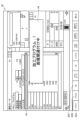
- FIG. FIG. 4 is a diagram showing a screen displayed by the numerical controller according to the first embodiment when selecting a machining program
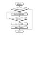
- FIG. 4 is a flowchart showing a processing procedure of processing executed by a mobile terminal included in the communication system according to the first embodiment
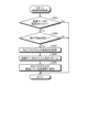
- 4 is a flowchart showing a processing procedure of processing executed by the numerical controller according to the first embodiment
- FIG. 2 shows a configuration of a communication system including a numerical control device according to a second embodiment
- FIG. 10 is a diagram showing a screen when editing a machining program, displayed by the numerical control device according to the second embodiment; 4 is a flow chart showing a processing procedure of processing executed by the numerical controller according to the second embodiment; FIG. 10 is a diagram showing a screen displayed by the numerical control device according to the third embodiment when the machine tool is in operation; FIG. 10 is a diagram showing a screen for associating image data with a machining program, displayed by the numerical controller according to the third embodiment; FIG. 10 is a flow chart showing a processing procedure of processing executed by a numerical control device according to a third embodiment; FIG. The figure which shows the structure of the communication system provided with the numerical control apparatus concerning Embodiment 4. FIG.
- FIG. 11 is a diagram showing a screen displayed by the numerical control device according to the fourth embodiment during a matching operation;
- FIG. FIG. 10 is a flow chart showing a processing procedure of processing executed by a numerical control device according to a fourth embodiment;
- FIG. FIG. 4 is a diagram showing a hardware configuration example for realizing the numerical controllers according to the first to fourth embodiments;
- FIG. 1 is a diagram showing a configuration of a communication system including a numerical control device according to Embodiment 1.
- the communication system 100A includes a numerical control (NC) device 1A and a mobile terminal 2 .
- NC numerical control
- the numerical controller 1A is a device that controls industrial machines such as machine tools, injection molding machines, electric discharge machines, and press machines.
- Examples of the mobile terminal 2 are smart phones, tablet PCs (Personal Computers), mobile phones, and the like.
- the industrial machine controlled by the numerical control device 1A is a machine tool that mainly performs metal processing
- the industrial machine controlled by the numerical control device 1A may be any machine.
- the numerical controller 1A is mounted, for example, on a machine tool such as a machining center or a lathe.
- the numerical controller 1A stores a machining program for machining metal.
- the numerical controller 1A analyzes the machining program and transmits the analysis result as a drive command to a drive section including motors that drive tools and workpieces (workpieces). Functions for sending commands to these drive units are omitted in FIG.
- the mobile terminal 2 is a terminal capable of capturing and transmitting an image.
- the numerical controller 1A has a communication section 11, a control section 12, storage sections 13, 14, and 15, which are a plurality of storage sections, an input section 16, and a display section 17.
- the mobile terminal 2 has a communication section 21 , an application 22 , a storage section 23 , a display section 24 and an imaging section 25 .
- the communication unit 21 is the first communication unit
- the communication unit 11 is the second communication unit.
- the storage units 13 to 15 are the first storage device
- the storage unit 23 is the second storage device.
- the communication unit 11 performs mutual data communication with an external device such as the mobile terminal 2 .
- the communication unit 11 included in the numerical control device 1A performs data communication with the communication unit 21 included in the mobile terminal 2 .
- the communication unit 11 receives, for example, image data (image data 231 to be described later) of a processed object sent from the communication unit 21 of the mobile terminal 2 .
- the communication unit 11 and the communication unit 21 perform wireless communication, for example, via a wireless LAN (Local Area Network), and the communication unit 11 can receive the image data 231 even from a location remote from the mobile terminal 2 .
- the communication means used by the communication units 11 and 21 is not limited to the wireless LAN.
- the communication units 11 and 21 may execute communication using a wired LAN, or may execute communication using a USB (Universal Serial Bus) cable, Bluetooth (registered trademark), infrared communication, or the like.
- the storage unit 13 has a machining program storage area 131 and an image storage area 132 .
- the storage unit 14 has a machining program storage area 141 and an image storage area 142 .
- the storage unit 15 has a machining program storage area 151 , an image storage area 152 and a selection program storage area 153 . Machining program storage areas 131, 141, and 151 are the first storage areas. Image storage areas 132, 142, and 152 are second storage areas. Further, in Embodiment 1, the selected program storage area 153 is the third storage area.
- the machining program storage areas 131, 141, and 151 are areas for storing the machining programs
- the image storage areas 132, 142, and 152 are areas for storing the image data 231 sent from the mobile terminal 2.
- the image data 231 is, for example, data representing a result of processing performed using a processing program. That is, the image data 231 is image data representing the shape of the processed object. This image data 231 is displayed together with the machining program when the user such as an operator selects the machining program next time, so that the user can visually confirm the machining program.
- the selected program storage area 153 stores information on the machining program specified by the user, that is, information indicating the machining program to be executed (hereinafter referred to as "selected program information").
- the selected program information is information indicating a state in which the machining program can be executed. Therefore, the state in which the selected program information is stored in the selected program storage area 153 is the state in which the machining program can be executed.
- the selected program information stored in the selected program storage area 153 may be any information as long as it can identify the machining program.
- An example of the selected program information stored in the selected program storage area 153 is the machining program name of the selected machining program.
- the selected program information may be the file name of the machining program.
- the storage units 13 to 15 are devices that can store data such as hard disks and non-volatile memories.
- the storage units 13 to 15 may be four or more.
- the storage unit 13 is a hard disk
- the storage unit 14 is an SD (Secure Digital) card
- the storage unit 15 is an internal memory.
- the input unit 16 receives information from outside the numerical control device 1A and inputs the information to the control unit 12 .
- the input unit 16 is composed of input means such as a keyboard, buttons, or a mouse.
- the input unit 16 accepts an input such as a command to the numerical control device 1A by the user, an NC program that is a machining program, parameters, and the like, and inputs them to the control unit 12 .
- the display unit 17 is configured by display means such as a liquid crystal display device.
- the display unit 17 displays the information processed by the control unit 12 on the display screen.
- the display unit 17 displays, for example, a machining program name, an image of a workpiece (an image corresponding to the image data 231), and the like.
- An example of the display unit 17 is a liquid crystal touch panel.
- the display section 17 is a liquid crystal touch panel, some functions of the input section 16 are arranged on the display section 17 .
- the control unit 12 controls the communication unit 11, the storage units 13 to 15, the input unit 16, and the display unit 17.
- the control unit 12 has a search unit 121 and a selection unit 122 .
- the search unit 121 searches for a storage unit for saving the image data 231 sent from the mobile terminal 2 . Specifically, the search unit 121 determines which storage unit stores the processing program corresponding to the selected program information stored in the selected program storage area 153, that is, the processing program corresponding to the image data 231. search for.
- the selection unit 122 selects the machining program to be executed from among the machining programs stored in the machining program storage areas 131, 141, 151 of the storage units 13, 14, 15.
- the machining program to be executed from now on is the machining program designated by the user.
- the selection unit 122 causes the selected program storage area 153 to store information indicating which machining program has been selected. That is, the selection unit 122 causes the selected program storage area 153 to store selected program information indicating the machining program specified by the user.
- the control unit 12 treats the file name of the image data 231 as the processing program name of the processing program used for processing. Set to the same name. Note that the file extension of the image data 231 and the file extension of the processing program are different.
- the communication unit 21 of the mobile terminal 2 performs data communication with an external device such as the numerical controller 1A.
- the application 22 is software that executes a function of providing the numerical control device 1A with image data 231 to be associated with the machining program.
- the application 22 has an application processing section 221 and an image conversion section 222 .
- the application processing unit 221 When the application processing unit 221 receives an imaging command from the user, it causes the imaging unit 25 to perform imaging.
- the image conversion unit 222 executes image conversion of the image data 231 . Specifically, the image conversion section 222 performs image conversion of the image data 231 so that the numerical control device 1A can perform data processing using the image data 231 .
- the storage unit 23 is composed of non-volatile memory such as a hard disk and SRAM (Static Random Access Memory).
- the storage unit 23 stores image data 231 of the image captured by the imaging unit 25 and the like.
- the display unit 24 is a display such as liquid crystal or organic EL (Electro Luminescence), and displays the state of the mobile terminal 2, images captured by the imaging unit 25, and the like. This allows the user to check the state of the mobile terminal 2, the image captured by the imaging unit 25, and the like.
- the mobile terminal 2 may have a touch panel. In this case, the user can operate the mobile terminal 2 with respect to the display unit 24 . If the mobile terminal 2 does not have a touch panel, the mobile terminal 2 has an operation section in addition to the display section 24 .
- the imaging unit 25 is a camera configured using a CCD (Charge Coupled Device), CMOS (Complementary Metal Oxide Semiconductor), or the like.
- the imaging unit 25 captures an image of a workpiece machined by the machine tool and acquires image data 231 corresponding to the image of the workpiece.
- the image captured by the mobile terminal 2 is associated with the processing program corresponding to the image by the numerical control device 1A, and when the user selects the processing program next time, the processing program is displayed by displaying the image. A process for visually confirming is explained.
- the user When starting machining by the machine tool, the user operates the input unit 16 and the display unit 17. That is, the user inputs a machining start command to the numerical controller 1A.
- the selection unit 122 of the control unit 12 selects the machining program specified by the user from among the machining programs stored in the machining program storage areas 131, 141, and 151 of the storage units 13 to 15, that is, the program to be executed from now. Select the machining program to be used.
- the machining program designated by the user is the first machining program.
- the control unit 12 reads out the selected machining program, and the selection unit 122 causes the selected program storage area 153 to store selected program information indicating which machining program is being selected.
- the machining program read by the control unit 12 is written in a main memory (not shown).
- a state in which the selected program storage area 153 stores selected program information is an executable state (search state) in which processing can be executed.
- search state an executable state
- the numerical controller 1A starts controlling the machine tool.
- the control unit 12 executes the machining program written in the main memory.
- the motor of the machine tool operates, and the machine tool starts machining metal or the like using the tool.
- the selected program storage area 153 continues to store the selected program information.
- the image of the processed object using the mobile terminal 2 is performed.
- the user uses the portable terminal 2 to capture an image of a workpiece as a result of machining in a state in which the machining program is executable, that is, in a state in which the selected program information is stored in the selected program storage area 153 .
- the mobile terminal 2 activates the application 22 that provides the numerical controller 1A with image data 231 to be associated with the processing program, and causes the display unit 24 to display the processing content of the application 22 .
- the application processing unit 221 of the application 22 becomes capable of capturing an image using the imaging unit 25 .
- the application processing unit 221 starts imaging using the imaging unit 25 .
- the application processing unit 221 causes the storage unit 23 to store the image data 231 of the image captured by the imaging unit 25 .
- the image conversion unit 222 of the application 22 converts the image data 231 into an image.
- Image conversion includes resizing an image and changing its format.
- the image conversion unit 222 reads format information 232 stored in the storage unit 23 and performs image conversion according to the format information 232 .
- the format information 232 is information specifying the size of the image after image conversion, the format of the image after image conversion, and the like.
- the format information 232 specifies the size of an image that can be displayed by the numerical controller 1A, the format that can be processed by the numerical controller 1A, and the like. Therefore, the image conversion unit 222 uses the format information 232 to convert the image data 231 into a format for displaying the image of the workpiece on the numerical control device 1A.
- the format information 232 stored in the storage unit 23 is stored in the application 22 in advance. This format information 232 is stored in the storage unit 23 of the mobile terminal 2 from the installation data when the mobile terminal 2 installs the application 22 .
- the image conversion unit 222 reads the image data 231 after image conversion from the storage unit 23 and stores it in a temporary storage area (not shown) that temporarily stores the data. After that, the application 22 causes the communication section 21 to transmit the image data 231 . As a result, the communication unit 21 reads out the image data 231 from the data temporary storage area and transmits the image data 231 to the communication unit 11 of the numerical controller 1A. Note that the number of pieces of image data 231 transmitted by the communication unit 21 for one processing (one processing program) is not limited to one, and may be plural.
- the numerical controller 1A saves the received image data 231 in a temporary storage area (not shown) that temporarily stores the data.
- the search unit 121 of the control unit 12 searches for a storage unit (storage destination) for storing the image data 231 stored in the temporary storage area. That is, the search unit 121 searches in which storage unit in the numerical controller 1A the machining program corresponding to the selected program information stored in the selected program storage area 153 is stored. For example, when the selected program information stored in the selected program storage area 153 is a program name, the search unit 121 searches the storage unit 13, the storage unit 14, and the storage unit 15 in order for the program name.
- the order (priority) of the storage units searched by the search unit 121 is determined in advance by the numerical control device 1A, for example. That is, the search unit 121 searches for machining programs in a predetermined order in a plurality of storage units. Note that the search unit 121 may search for a machining program according to the search order specified by the user for a plurality of storage units. In this case, the order in which the storage units are searched is determined by the user using a parameter or the like indicating the order of search. Thereby, the search unit 121 can improve the search speed. In addition, when different storage units store processing programs with the same program name but different contents, the user sets the order of the storage units to be searched so that the image data 231 can correspond to the processing program intended by the user. can be attached. As described above, the order of the storage units searched by the search unit 121 may be determined in advance by the numerical control device 1A, or may be determined by the user using a parameter or the like indicating the search order.
- the search unit 121 finds the storage destination of the corresponding machining program, that is, finds the machining program corresponding to the selected program information
- the search unit 121 saves the image data 231 in the image storage area of the same storage unit as the found machining program. .
- the search unit 121 stores the image data 231 in the image storage area 142 .
- the search unit 121 sets the file name of the image data 231 to the same name as the processing program name of the processing program and saves it in the storage unit 14 . This completes the correspondence between the image data 231 and the processing program in the communication system 100A.
- the numerical control device 1A automatically associates the image data 231 with the processing program. That is, the user who wants to make the correspondence selects a machining program to be used for machining the workpiece in front of the screen of the numerical controller 1A, and starts machining the workpiece. After the machining is completed, the portable terminal 2 takes an image of the workpiece while the machining program is still selected in the numerical controller 1A, and transmits image data 231 to the numerical controller 1A. Thereby, the numerical controller 1A associates the received image data 231 with the selected machining program used for machining.
- the numerical controller 1A associates the received image data 231 with the selected machining program used for machining, so the user does not need to select the machining program. Therefore, in the numerical control device 1A, the number of processing procedures for associating the image data 231 captured by the portable terminal 2 with the processing program is reduced. In addition, when the user associates the image data 231 with the processing program, erroneous association such as selection error of the processing program can be prevented.
- the data sent from the communication unit 21 of the mobile terminal 2 to the communication unit 11 of the numerical control device 1A is only image data, and the setting data and the like that are required in the conventional technology are unnecessary. Therefore, the communication system 100A can prevent the storage destination of the image data from being lost when the setting data cannot be received normally due to a communication error or the like, unlike the conventional technology.
- FIG. 2 is a diagram showing a screen displayed by the numerical controller according to the first embodiment when selecting a machining program.
- the control unit 12 causes the display unit 17 to display a screen 41 for selecting a machining program.
- a screen 41 is displayed when a machining program is selected by the user.
- a list 31 of machining programs to be selected by the user is displayed. Also, on the screen 41, an image 32 of a workpiece corresponding to the machining program selected by the user is displayed. This image 32 is an image displayed using the image data 231 having the same file name as the processing program name of the processing program selected by the user.
- the selection unit 122 When the user operates the input unit 16 to select any machining program from the list 31 displayed on the screen 41, the selection unit 122 highlights the selected machining program. Further, the selection unit 122 searches the storage units 13 to 15 for the machining program selected by the user. In addition, the selection unit 122 causes the selected program storage area 153 to store the selected program information (for example, the name of the machining program) indicating the searched machining program, that is, the machining program to be executed from now on.
- the selected program information for example, the name of the machining program
- the search unit 121 retrieves the image data 231 having the same file name as the processing program name of the processing program selected by the user. Search from within. If there is image data 231 with the same name, the search unit 121 causes the display unit 17 to display it like an image 32 .
- the search unit 121 sets the search range for the image data 231 to the storage unit in which the processing program selected by the user is saved. , and may be extended to other storage units.
- FIG. 3 is a flowchart of a processing procedure of processing executed by a mobile terminal included in the communication system according to the first embodiment
- the mobile terminal 2 captures an image of the workpiece according to the user's operation. Specifically, the mobile terminal 2 activates the application 22 according to the user's operation. Furthermore, when the user performs an image capturing operation, the application processing unit 221 uses the image capturing unit 25 to perform image capturing.
- the application 22 determines whether or not imaging has been performed (step S101). If imaging has not been performed (step S ⁇ b>101 , No), the mobile terminal 2 terminates the process of transferring the image data 231 .
- step S101 Yes
- the application 22 stores the image data 231 of the image captured by the imaging unit 25 in the storage unit 23.
- the application 22 selects a device to which the image data 231 is to be transferred (step S102).
- a device to which the mobile terminal 2 transmits the image data 231 is a numerical control device.
- the application 22 selects, for example, a numerical controller with which communication has been established with the mobile terminal 2 or a numerical controller with which communication has been made in the past.
- the application 22 causes the display unit 24 to display numerical controllers with which communication has been established with the portable terminal 2, or numerical controllers with which communication has been established in the past, so that the user can select a numerical controller.
- the application 22 of Embodiment 1 selects the numerical controller 1A.
- step S103 the application 22 confirms whether or not the image data 231 can be transferred to the selected numerical controller 1A (step S103). If the selected numerical control device 1A is not in an executable state in which processing can be executed, that is, if transfer is not possible (step S103, No), the application 22 returns to the process of step S102. Further, if the selected numerical control device 1A is not equipped with a function for executing the correspondence between the image data 231 and the processing program, the application 22 determines that the transfer is impossible, and performs the processing of step S102. back to
- the image conversion unit 222 reads the format information 232 stored in the storage unit 23. Then, the image conversion unit 222 performs image conversion such as format conversion on the image data 231 according to the format information 232 (step S104). Thereafter, the application 22 transfers the image data 231 that has undergone image conversion from the communication section 21 to the numerical controller 1A (step S105).
- FIG. 4 is a flowchart of a processing procedure of processing executed by the numerical controller according to the first embodiment
- the selection unit 122 selects the specified machining program based on this command. Read from the storage units 13-15. Specifically, the selection unit 122 reads the machining program specified by the user from among the machining programs stored in the machining program storage areas 131 , 141 , and 151 .
- the selection unit 122 causes the selected program storage area 153 of the storage unit 15 to store selected program information indicating which machining program is being selected.
- the numerical controller 1A becomes ready for processing.
- the machine tool starts machining according to the control by the controller 12 .
- the control unit 12 determines whether or not the image data 231 has been transferred from the mobile terminal 2 (step S201). When the machining using the machining program corresponding to the selected program information stored in the selected program storage area 153 is completed, image data 231 is sent from the mobile terminal 2 to the numerical controller 1A.
- the communication unit 11 of the numerical controller 1A receives the image data 231. If the image data 231 has not been transferred from the portable terminal 2 (step S201, No), the numerical controller 1A terminates the process of associating the image data 231 with the processing program.
- the search unit 121 determines whether or not it is in an executable state in which processing can be performed (step S202). If it is not in the executable state (step S202, No), the numerical controller 1A terminates the process of associating the image data 231 with the processing program. In this case, the numerical controller 1A may notify the portable terminal 2 that the image data 231 has not been saved.
- the search unit 121 searches for the storage location of the machining program corresponding to the selected program information stored in the selected program storage area 153 (step S203).
- the selected program information is information indicating a processing program corresponding to the image data 231 transferred from the mobile terminal 2 .
- the search unit 121 When the search unit 121 finds the storage location of the corresponding processing program, it saves the image data 231 in the image storage area of the same storage unit as the found processing program. In this case, the search unit 121 renames the file name of the image data 231 (step S204). Specifically, the search unit 121 rewrites the file name of the image data 231 to the same name as the processing program name of the processing program that found the storage destination. Then, the search unit 121 saves the image data 231 whose file name has been rewritten in the image storage area of the storage unit storing the processing program whose storage destination has been found (step S205). Thereby, the numerical controller 1A associates the image data 231 transferred from the portable terminal 2 with the processing program.
- the image data 231 associated by the numerical control device 1A is data representing the image of the workpiece that has been processed under the control of the numerical control device 1A.
- the machining program associated with the numerical controller 1A is the machining program used for control by the numerical controller 1A. Therefore, the numerical controller 1A can associate the machining program used for machining with the image data 231 of the workpiece machined using this machining program.
- the numerical controller 1A repeats the correspondence between the image data 231 and the processing program. As a result, image data 231 corresponding to the processing program is accumulated.
- the search unit 121 searches the image data 231 having the same file name as the processing program name of the processing program specified by the user from within the image storage area of the storage unit in which the processing program specified by the user is stored. do. If there is image data 231 with the same name, the search unit 121 causes the display unit 17 to display an image corresponding to the image data 231 .
- control unit 12 may create a data table showing the correspondence between the image data 231 and the processing program, and manage the correspondence between the image data 231 and the processing program using this data table.
- search unit 121 searches the image data 231 corresponding to the processing program using the data table.
- the numerical controller 1A executes the association process, so that the user can use the portable terminal 2 to search for the machining program. you don't have to. For this reason, even when images of a workpiece are repeatedly captured by repeated processing, the user does not need to search for a processing program associated with the image data 231 each time.
- the control unit 12 of the numerical controller 1A controls the machining of the workpiece using the machining program specified by the user among the machining programs. Then, when the image data 231 is sent from the portable terminal 2 in an executable state in which processing can be executed, the numerical control device 1A searches the storage units 13 to 15 for the processing program used for control, 2 is associated with the image data 231 sent from 2. Thereby, the communication system 100A can easily associate the image of the workpiece (image data 231) with the processing program.
- the numerical control device 1A causes the selected program storage area 153 to store the selected program information and at least one of the processing start time and the processing end time in association with each other, and the portable terminal 2 stores the image data 231 and the imaging time. may be linked and transmitted to the numerical controller 1A.
- the search unit 121 searches for a processing program whose processing start time or processing end time is before and closest to the imaging time, and associates it with the image data 231 .
- the communication system 100A can obtain the same effects as those described in the first embodiment.
- Embodiment 2 Next, Embodiment 2 will be described with reference to FIGS. 5 to 7.
- FIG. The numerical controller of Embodiment 2 associates the image data 231 with the machining program when the state of the numerical controller is the edit state of the machining program.
- the state of the numerical controller is the edit state of the machining program.
- there is an additional procedure for putting the machining program into an edit state immediately after machining but there is an advantage that the association work becomes explicit for the user.
- FIG. 5 is a diagram showing the configuration of a communication system provided with a numerical controller according to the second embodiment. 5 that achieve the same functions as those of the communication system 100A of the first embodiment shown in FIG. 1 are denoted by the same reference numerals, and overlapping descriptions are omitted.
- the communication system 100B includes a numerical control device 1B instead of the numerical control device 1A compared to the communication system 100A. That is, the communication system 100B includes a numerical control device 1B and a mobile terminal 2.
- the numerical control device 1B differs from the numerical control device 1A in the storage areas included in the storage unit 15. Specifically, the storage unit 15 of the numerical controller 1B has an edit program storage area 154 instead of the selected program storage area 153, as compared with the storage unit 15 of the numerical controller 1A. As a result, the storage unit 15 of the numerical controller 1B stores information of the machining program being edited (hereinafter referred to as edited program information) instead of the selected program information, compared to the storage unit 15 of the numerical controller 1A. do.
- the edited program information is information indicating a state in which the machining program is edited. Therefore, the state in which the editing program information is stored in the editing program storage area 154 is the state in which the machining program is being edited.
- the editing program storage area 154 is the third storage area.
- the editing program information stored in the editing program storage area 154 may be any information as long as it can identify the machining program.
- An example of the editing program information stored in the editing program storage area 154 is the machining program name of the machining program being edited.
- the editing program information may be the file name of the machining program being edited.
- the image captured by the portable terminal 2 is associated with the processing program corresponding to the image by the numerical control device 1B, and when the user selects the processing program next time, the image is displayed so that the processing program can be changed. A process for visually confirming is explained.
- FIG. 6 is a diagram showing a screen displayed by the numerical controller according to the second embodiment when editing a machining program.
- a screen 42 is displayed when the machining program can be edited by the user.
- the user can edit the machining program by operating the keyboard on the input unit 16 or the like while confirming the displayed machining program.
- FIG. 6 shows a case where the machining program displayed on the editing screen 51 is the machining program 52 . That is, the screen 42 shown in FIG. 6 is in a state in which the machining program 52 can be edited.
- a message 53 indicating that the machining program 52 is being edited is displayed. This allows the user to check whether the machining program 52 is in the edit state.
- the user selects a desired machining program by a method similar to that described in Embodiment 1.
- the control unit 12 reads out the selected machining program and writes it into the main memory.
- the motor of the machine tool is activated, and the machine tool starts machining metal or the like using the tool.
- the control unit 12 causes the display unit 17 to display a screen 42 to enter the state of editing the processing program.
- the selection unit 122 searches the storage units 13 to 15 for the machining program selected by the user.
- the selection unit 122 causes the editing program storage area 154 to store the editing program information indicating the searched machining program, that is, the machining program used for machining. That is, the selection unit 122 causes the editing program storage area 154 to store the machining program in the editing state.
- the mobile terminal 2 captures an image of the workpiece after machining while the machining program is being edited, ie, the machining program is stored in the editing program storage area 154 . Thereafter, the portable terminal 2 transfers the image data 231 to the numerical controller 1B.
- the numerical controller 1B associates the image data 231 with the machining program being edited by the same method as the numerical controller 1A. Then, when the user selects a new machining program, the numerical controller 1B displays an image of the image data 231 corresponding to the machining program in the same manner as the numerical controller 1A.
- the method of associating the image data 231 with the machining program and the method of visually confirming the machining program using the image data 231 by the numerical controller 1B are the same as those of the numerical controller 1A.
- the processing procedure of the processing executed by the mobile terminal 2 is the same as in the first embodiment. That is, in the second embodiment, as in the first embodiment, the mobile terminal 2 executes processing according to the processing procedure shown in FIG.
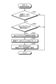
- FIG. 7 is a flowchart of a processing procedure of processing executed by the numerical controller according to the second embodiment
- the numerical controller 1B executes the process of step S302 instead of the process of step S202 in FIG. 4, compared to the process executed by the numerical controller 1A. That is, when the image data 231 is transferred from the portable terminal 2 (step S201, Yes), the numerical control device 1B determines whether the search unit 121 is in the editing state of the machining program (step S302). . If it is not in the editing state (step S302, No), the numerical controller 1B ends the process of associating the image data 231 with the processing program. In this case, the numerical controller 1B may notify the portable terminal 2 that the image data 231 has not been saved.
- step S302, Yes the numerical controller 1B executes the processes of steps S203 to S205 described in FIG.
- the numerical controller 1B stores the processing program used for control from the storage units 13 to 15. It is searched and associated with the image data 231 sent from the mobile terminal 2 .
- the communication system 100B can easily associate the image of the workpiece with the processing program, like the communication system 100A.
- the numerical control device 1B causes the editing program storage area 154 to save the editing program information and at least one of the editing start time and the editing end time in association with each other, and the portable terminal 2 stores the image data 231 and the imaging time. may be linked and transmitted to the numerical controller 1B.
- the search unit 121 searches for a processing program whose edit start time or edit end time is closest to the imaging time, and associates it with the image data 231 .
- the communication system 100B can obtain the same effects as those described in the second embodiment.
- Embodiment 3 Next, Embodiment 3 will be described with reference to FIGS. 8 to 10.
- FIG. The numerical controller of Embodiment 3 associates the image data 231 with the machining program when the state of the numerical controller is the machining program selection state. That is, when the user operates the numerical controller to select a machining program to be associated with the image data 231, the numerical controller associates the image data 231 with the machining program.
- the user's operating procedure is the same as in the second embodiment.
- a numerical controller 1A similar to that of the first embodiment is also used in the third embodiment. That is, the configuration of the numerical controller 1A of Embodiment 3 is the configuration shown in FIG.
- the image captured by the mobile terminal 2 is associated with the processing program corresponding to the image by the numerical control device 1A, and when the user selects the processing program next time, the processing program is displayed by displaying the image. A process for visually confirming is explained.
- the user selects a desired machining program for the numerical controller 1A of the third embodiment in the same manner as the method described in the first embodiment.
- the control unit 12 causes the display unit 17 to display a screen showing information regarding the operation of the machine tool during machining of the workpiece.
- FIG. 8 is a diagram showing a screen displayed by the numerical controller according to the third embodiment when the machine tool is in operation.
- the screen 43 is a screen that displays information during operation of the machine tool.
- the control unit 12 continues to display the screen 43 during operation of the machine tool even after the machining is completed.
- An image-related menu button 61 is displayed on the screen 43 .
- the image-related menu button 61 is a button for displaying a screen (screen 44 described later) for associating the image data 231 with the processing program when pressed by the user.
- FIG. 9 is a diagram showing a screen for associating image data with a processing program, displayed by the numerical controller according to the third embodiment.
- selection buttons 62A-62C for selecting the storage units 13-15 are displayed.
- Selection button 62A is a button corresponding to storage unit 13
- selection button 62B is a button corresponding to storage unit 14
- selection button 62C is a button corresponding to storage unit 15 .
- FIG. 9 shows a case where storage units 13 and 14 are memories and storage unit 15 is a hard disk.
- the control unit 12 selects the storage unit 13.
- the control unit 12 selects the storage unit 14 by the user pressing the selection button 62B.
- the control unit 12 selects the storage unit 15 when the selection button 62C is pressed by the user.
- FIG. 9 shows a state in which the selection button 62A is pressed.
- the user After the user presses the selection button 62A, the user operates the keyboard or the like to press the selection command button 63 for commanding the selection state of the machining program, and then presses the determination button (not shown).
- the control unit 12 may cause the display unit 17 to display a message 64 indicating that the image data 231 is being associated with the processing program.
- the selection unit 122 of the numerical controller 1A causes the selected program storage area 153 to store information indicating which machining program has been selected (hereinafter referred to as selection state information).
- the selection state information is information indicating the state in which the machining program is selected. Therefore, the state in which the selection state information is stored in the selection program storage area 153 is the state in which the machining program is selected.
- the mobile terminal 2 captures an image of the workpiece after machining while the machining program is selected, that is, the selection status information is stored in the selected program storage area 153 . Thereafter, the portable terminal 2 transfers the image data 231 to the numerical controller 1A.
- Numerical control device 1A associates image data 231 with the selected machining program by a method similar to that described in the first embodiment. Then, when the user selects a new machining program, the numerical controller 1A displays an image of the image data 231 corresponding to the machining program by the same method as described in the first embodiment.
- the method of associating the image data 231 with the processing program and the method of visually confirming the processing program using the image data 231 in the third embodiment are the same as in the first embodiment.
- the processing procedure of the processing executed by the mobile terminal 2 is the same as in the first embodiment. That is, in the third embodiment, as in the first embodiment, the mobile terminal 2 executes processing according to the processing procedure shown in FIG.
- FIG. 10 is a flowchart of a processing procedure of processing executed by the numerical controller according to the third embodiment.
- the numerical control apparatus 1A of Embodiment 3 executes the process of Step S402 instead of the process of Step S202 in FIG. That is, when the image data 231 is transferred from the portable terminal 2 (step S201, Yes), the numerical controller 1A of the third embodiment determines whether the search unit 121 is in the machining program selection state. (step S402). If it is not in the selected state (step S402, No), the numerical controller 1A terminates the process of associating the image data 231 with the processing program. In this case, the numerical controller 1A may notify the portable terminal 2 that the image data 231 has not been saved.
- step S402 If it is in the selected state (step S402, Yes), the numerical controller 1A executes the processes of steps S203 to S205 described with reference to FIG.
- the numerical controller 1A when the image data 231 is sent from the portable terminal 2 while the processing program is selected, stores the processing program used for control from the storage units 13 to 15. It is searched and associated with the image data 231 sent from the mobile terminal 2 . As a result, the numerical controller 1A can easily associate the image of the workpiece with the machining program, as in the first embodiment.
- Embodiment 4 When operated by the user, the numerical controller of Embodiment 4 associates the image data 231 with the processing program according to the operation.
- the fourth embodiment since the association is executed according to the user's operation, unlike the first to third embodiments, confirmation of the state of the numerical controllers 1A and 1B and setting to the numerical controllers 1A and 1B in advance are required. becomes unnecessary. Therefore, even if the numerical controllers 1A and 1B are not in the state described in the first to third embodiments, there is an advantage that the image data 231 can be associated with the machining program.
- FIG. 11 is a diagram showing the configuration of a communication system provided with a numerical controller according to the fourth embodiment. Among the constituent elements in FIG. 11, the constituent elements that achieve the same functions as those of the communication system 100A of Embodiment 1 shown in FIG.
- the communication system 100C includes a numerical control device 1C instead of the numerical control device 1A, as compared with the communication system 100A. That is, the communication system 100C includes a numerical control device 1C and a mobile terminal 2.
- the numerical control device 1C differs from the numerical control device 1A in the storage areas included in the storage unit 15 .
- the storage unit 15 of the numerical control device 1C has a transfer image storage area 155 instead of the selected program storage area 153 compared to the storage unit 15 of the numerical control apparatus 1A.
- the storage unit 15 of the numerical control device 1C stores the image data 231 transferred from the portable terminal 2 instead of the selected program information, as compared with the storage unit 15 of the numerical control device 1A.
- the control section 12 does not have the searching section 121 as compared with the numerical control device 1A.
- the image captured by the portable terminal 2 is associated with the processing program corresponding to the image by the numerical control device 1C, and when the user selects the processing program next time, the image is displayed to display the processing program. A process for visually confirming is explained.
- the numerical controller 1C associates the image data 231 with the processing program regardless of the state of the numerical controller 1C. Further, the numerical controller 1C may associate the image data 231 with the processing program in a state different from the states of the numerical controllers 1A and 1B described in the first to third embodiments. That is, the numerical control device 1C associates the image data 231 with the machining program when none of the executable state in which machining can be executed, the editing state of the machining program, and the selection state of the machining program by user operation is performed.
- the mobile terminal 2 takes an image of the workpiece.
- the mobile terminal 2 converts the image data 231 of the imaged image according to the format information 232, and transfers it to the numerical controller 1C.
- the process of the mobile terminal 2 capturing an image of the workpiece and transferring it to the numerical control device 1C is the same as that of the numerical control device 1A of the first embodiment.
- the numerical controller 1C stores the image data 231 received by the communication unit 11 in the transfer image storage area 155. At that time, in consideration of storing a plurality of image data 231, the numerical controller 1C sets a file name that does not have the same file name as the other image data 231 using numbers starting from 1, random character strings, and the like. Save the image data 231 as a file.
- the numerical control device 1C After the numerical control device 1C saves one or more image data 231 in one or more transfer image storage areas 155, the user performs an association operation. A user performs a matching operation by operating the numerical controller 1C.
- the user operates the numerical control device 1C from the input section 16 using a keyboard or the like while confirming the screen displayed on the display section 17 .
- a screen displayed by the display unit 17 when the user performs the association operation will be described.
- FIG. 12 is a diagram showing a screen displayed by the numerical control device according to the fourth embodiment during a matching operation.
- Selection buttons 62A to 62C for selecting the storage units 13 to 15 are displayed on the screen 45 displayed by the display unit 17 when the user performs the association operation.
- the screen 45 also displays an image data selection button 94 for instructing the selection state of the image data 231 .
- the image data selection button 94 is a button for selecting the image data 231 desired by the user from among the plurality of image data 231 . Therefore, one image data selection button 94 is associated with one image data 231 .
- FIG. 12 shows a state in which the selection button 62A is pressed. After the user presses the selection button 62A, the user operates the keyboard or the like to press the selection command button 63 for commanding the selection state of the machining program, and then presses the determination button (not shown). Sets the selected machining program to the selected state.
- the control unit 12 puts the selected image data 231 into the selection state.
- control unit 12 associates the selected processing program with the selected image data 231 . That is, the control unit 12 associates the processing program corresponding to the selection command button 63 with the image data 231 corresponding to the image data selection button 94 .
- control unit 12 associates the processing program in the selected state with the image data 231 in the selected state. good too. That is, either the image data 231 or the processing program may be selected first.
- control unit 12 may cause the screen 45 to display in which state the procedure included in the association operation is.
- the user is notified of the state of the procedure included in the association operation by displaying it on the screen 45 using a comment column 95 or the like.
- the comment column 95 for example, "selecting a machining program” indicating that the machining program is selected, "selecting image data” indicating that the image data 231 is selected, and indicating that the association operation is completed. "Associating operation completed” or the like is displayed.
- FIG. 12 shows a case where "selecting a machining program" is displayed in the comment column 95 indicating the state of the procedure included in the association operation.
- the control unit 12 saves the image data 231 associated with the image data 231 in the storage unit. Specifically, the control unit 12 transfers the image data 231 stored in the transfer image storage area 155 and selected by the association operation to the storage in which the processing program selected by the association operation is saved. image storage area. At that time, the control unit 12 changes the file name of the image data 231 to the same name as the processing program name, and saves the image data 231 in the storage unit storing the processing program in the same manner as in the method described in the first embodiment. to save.
- the processing procedure of the processing executed by the mobile terminal 2 is the same as in the first embodiment. That is, in the fourth embodiment, as in the first embodiment, the mobile terminal 2 executes processing according to the processing procedure shown in FIG. However, in the fourth embodiment, the condition for checking whether or not transfer is possible in step S102 does not include the state of the numerical controller 1C. The portable terminal 2 determines whether or not the transfer is possible by whether or not the numerical control device 1C is equipped with a matching function.
- FIG. 13 is a flowchart of a processing procedure of processing executed by the numerical controller according to the fourth embodiment.
- the control unit 12 determines whether or not the image data 231 transferred from the portable terminal 2 is stored in the transfer image storage area 155 (step S501). If the transferred image data 231 is not saved (step S501, No), the numerical controller 1C terminates the process of associating the image data 231 with the processing program.
- step S501 Yes
- the control unit 12 selects a processing program to be associated according to the instruction from the user (step S502). Further, the control unit 12 selects the image data 231 to be associated according to the instruction from the user (step S503).
- the numerical controller 1C executes the processes of steps S204 and S205 described with reference to FIG. Note that the numerical controller 1C may execute either the process of step S502 or the process of step S503 first.
- the numerical controller 1C associates the image data 231 with the selected machining program according to the user's operation regardless of the state of the numerical controller 1C. Similarly, the image of the workpiece and the machining program can be easily associated with each other.
- FIG. 14 is a diagram showing a hardware configuration example for realizing the numerical controllers according to the first to fourth embodiments. Since the numerical controllers 1A to 1C have the same hardware configuration, the hardware configuration of the numerical controller 1A will be described here.
- the numerical controller 1A can be realized by the processor 100, the memory 200, the input device 300, the display device 400, and the communication device 500.
- An example of the processor 100 is a CPU (Central Processing Unit, central processing unit, processing unit, arithmetic unit, microprocessor, microcomputer, DSP (Digital Signal Processor)) or system LSI (Large Scale Integration).
- Examples of the memory 200 are RAM (Random Access Memory) and ROM (Read Only Memory).
- the numerical controller 1A is implemented by the processor 100 reading and executing a computer-executable control program for executing the operations of the numerical controller 1A stored in the memory 200.
- a control program which is a program for executing the operation of the numerical controller 1A, can be said to cause a computer to execute the procedure or method of the numerical controller 1A.
- the control program executed by the numerical controller 1A has a module configuration including the control unit 12, which are loaded onto the main memory and generated on the main memory.
- the input device 300 receives commands from the user and sends them to the processor 100 .
- the input device 300 also receives a machining program from an external device and sends it to the memory 200 .
- the input device 300 corresponds to the input section 16 .
- the memory 200 includes storage units 13 to 15 and the like.
- the memory 200 stores control programs, processing programs, image data 231, selection programs, and the like.
- the control program, processing program, image data 231 and selection program are sent to the processor 100 .
- the memory 200 is also used as a temporary storage area when the processor 100 executes various processes.
- the communication device 500 executes communication with the mobile terminal 2 and the like.
- a communication device 500 corresponds to the communication unit 11 .
- the display device 400 displays a screen 41 and the like.
- a display device 400 corresponds to the display section 17 .
- the control program may be stored in a computer-readable storage medium in an installable or executable format and provided as a computer program product. Also, the control program may be provided to the numerical controller 1A via a network such as the Internet. It should be noted that the functions of the numerical controller 1A may be partly realized by dedicated hardware such as a dedicated circuit, and partly realized by software or firmware.
- 1A to 1C numerical controller 2 mobile terminal, 11, 21 communication unit, 12 control unit, 13 to 15, 23 storage unit, 16 input unit, 17, 24 display unit, 22 application, 25 imaging unit, 31 list, 32 image, 41 to 45 screen, 51 editing screen, 52 processing program, 53, 64 message, 61 image related menu button, 62A to 62C selection button, 63 selection command button, 94 image data selection button, 95 comment field, 100 processor , 100A to 100C communication system, 121 search unit, 122 selection unit, 131, 141, 151 machining program storage area, 132, 142, 152 image storage area, 153 selection program storage area, 154 editing program storage area, 155 transfer image storage Area, 200 memory, 221 application processing unit, 222 image conversion unit, 231 image data, 232 format information, 300 input device, 400 display device, 500 communication device.
Landscapes
- Engineering & Computer Science (AREA)
- Human Computer Interaction (AREA)
- Manufacturing & Machinery (AREA)
- Physics & Mathematics (AREA)
- General Physics & Mathematics (AREA)
- Automation & Control Theory (AREA)
- Numerical Control (AREA)
Priority Applications (2)
| Application Number | Priority Date | Filing Date | Title |
|---|---|---|---|
| PCT/JP2021/036513 WO2023053459A1 (ja) | 2021-10-01 | 2021-10-01 | 通信システムおよび数値制御装置 |
| JP2022523034A JPWO2023053459A1 (https=) | 2021-10-01 | 2021-10-01 |
Applications Claiming Priority (1)
| Application Number | Priority Date | Filing Date | Title |
|---|---|---|---|
| PCT/JP2021/036513 WO2023053459A1 (ja) | 2021-10-01 | 2021-10-01 | 通信システムおよび数値制御装置 |
Publications (1)
| Publication Number | Publication Date |
|---|---|
| WO2023053459A1 true WO2023053459A1 (ja) | 2023-04-06 |
Family
ID=85782123
Family Applications (1)
| Application Number | Title | Priority Date | Filing Date |
|---|---|---|---|
| PCT/JP2021/036513 Ceased WO2023053459A1 (ja) | 2021-10-01 | 2021-10-01 | 通信システムおよび数値制御装置 |
Country Status (2)
| Country | Link |
|---|---|
| JP (1) | JPWO2023053459A1 (https=) |
| WO (1) | WO2023053459A1 (https=) |
Cited By (1)
| Publication number | Priority date | Publication date | Assignee | Title |
|---|---|---|---|---|
| WO2025069260A1 (ja) * | 2023-09-27 | 2025-04-03 | 株式会社Fuji | 加工提案表作成装置、加工提案表作成プログラム、及び通信端末用アプリケーションプログラム |
Citations (3)
| Publication number | Priority date | Publication date | Assignee | Title |
|---|---|---|---|---|
| JP2001255916A (ja) * | 2000-03-10 | 2001-09-21 | Sodick Co Ltd | 形彫放電加工装置のncプログラムの管理装置および管理方法 |
| JP2013257791A (ja) * | 2012-06-13 | 2013-12-26 | Nippon Denpa Co Ltd | インデックステーブル用制御装置 |
| JP2018082255A (ja) * | 2016-11-14 | 2018-05-24 | ファナック株式会社 | 通信システムおよび携帯端末 |
-
2021
- 2021-10-01 WO PCT/JP2021/036513 patent/WO2023053459A1/ja not_active Ceased
- 2021-10-01 JP JP2022523034A patent/JPWO2023053459A1/ja active Pending
Patent Citations (3)
| Publication number | Priority date | Publication date | Assignee | Title |
|---|---|---|---|---|
| JP2001255916A (ja) * | 2000-03-10 | 2001-09-21 | Sodick Co Ltd | 形彫放電加工装置のncプログラムの管理装置および管理方法 |
| JP2013257791A (ja) * | 2012-06-13 | 2013-12-26 | Nippon Denpa Co Ltd | インデックステーブル用制御装置 |
| JP2018082255A (ja) * | 2016-11-14 | 2018-05-24 | ファナック株式会社 | 通信システムおよび携帯端末 |
Cited By (1)
| Publication number | Priority date | Publication date | Assignee | Title |
|---|---|---|---|---|
| WO2025069260A1 (ja) * | 2023-09-27 | 2025-04-03 | 株式会社Fuji | 加工提案表作成装置、加工提案表作成プログラム、及び通信端末用アプリケーションプログラム |
Also Published As
| Publication number | Publication date |
|---|---|
| JPWO2023053459A1 (https=) | 2023-04-06 |
Similar Documents
| Publication | Publication Date | Title |
|---|---|---|
| JP6614763B2 (ja) | 情報処理装置、情報処理装置の制御方法及びプログラム | |
| EP3182683A1 (en) | Information processing apparatus and program | |
| JP6512982B2 (ja) | 通信装置、通信装置の制御方法及びプログラム | |
| CN105278887A (zh) | 信息处理系统和信息处理装置 | |
| JP2017130760A (ja) | システム、情報処理方法、情報処理装置およびプログラム | |
| JP5961375B2 (ja) | 画像形成システム、それに用いる携帯情報端末および画像形成装置 | |
| WO2023053459A1 (ja) | 通信システムおよび数値制御装置 | |
| US10209703B2 (en) | Communication system and mobile terminal | |
| EP3295659B1 (en) | Information processing system, information processing apparatus, information processing method, and information processing program | |
| JP2008245151A (ja) | 撮像装置、画像処理装置及び画像処理システム並びにこれらの制御方法、プログラム | |
| JP6134836B2 (ja) | 画像形成システムに用いる携帯情報端末および画像形成装置 | |
| JP6348494B2 (ja) | 生産設備 | |
| JP2016139342A (ja) | 装置連携による情報入力方法、情報処理装置、コンピュータプログラム | |
| US10855869B2 (en) | Information processing apparatus, information processing method, and storage medium storing program for activating applications | |
| CN109196454B (zh) | 可编程显示器、画面显示系统以及可编程显示器的控制方法 | |
| JP2017060089A (ja) | 画像処理装置 | |
| JP4380059B2 (ja) | 撮像システム、撮像装置、撮像方法及び記録媒体 | |
| JP6357563B2 (ja) | 画像形成システム、それに用いる携帯情報端末および画像形成装置 | |
| JP2011095882A (ja) | データ処理装置、画像形成装置、制御方法及びプログラム | |
| JP6407241B2 (ja) | 情報処理装置、制御方法およびプログラム | |
| JP4262684B2 (ja) | 機器操作ガイダンスシステム | |
| KR20200094975A (ko) | 그래픽 이미지 방식의 공작기계 팔레트 모니터 장치 및 그 표시방법 | |
| WO2019082429A1 (ja) | 製造作業支援システム、製造作業支援方法およびプログラム | |
| US20230035777A1 (en) | Information processing apparatus, control method thereof, and storage device | |
| JP2023019782A (ja) | 情報処理装置、情報処理システム、及び情報処理プログラム |
Legal Events
| Date | Code | Title | Description |
|---|---|---|---|
| WWE | Wipo information: entry into national phase |
Ref document number: 2022523034 Country of ref document: JP |
|
| 121 | Ep: the epo has been informed by wipo that ep was designated in this application |
Ref document number: 21959493 Country of ref document: EP Kind code of ref document: A1 |
|
| NENP | Non-entry into the national phase |
Ref country code: DE |
|
| 122 | Ep: pct application non-entry in european phase |
Ref document number: 21959493 Country of ref document: EP Kind code of ref document: A1 |